1
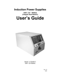
RST 60/100/200 Automatic Transfer Panel Printed U.S.A. 913-0104B 9-2004 Redistribution or publication of this document, by any means, is strictly prohibited. !" # # $ # % # ##$ $ $ PURPOSE This supplement updates the LT, LC, and RST Operator’s, Installation, and Service Manuals to include information on the 5-button exercise clock available on current production units. SUPPLEMENT USE Write Refer to Supplement on the pages of the manuals listed above that refer to the exercise clock. Insert this supplement inside the front cover of the manuals listed above. Page 1 of 8 Redistribution or publication of this document, by any means, is strictly prohibited. Page 2 of 8 Redistribution or publication of this document, by any means, is strictly prohibited. FIVE BUTTON EXERCISE CLOCKS NOTE: After one minute of button inactivity, the home menu (see Figure 2) will be redisplayed and any changes made that weren’t saved by pressing the OK button will be lost. Figure 3 also shows the following clock features. 24 18 6 D The available menu topics are displayed at the 123 456 7 12 top of the screen. OK MENU D When being programmed, indicators for change- over (SU/Wi) and the date (D/M/Y) are displayed beneath the menu topics. FIGURE 1. FIVE BUTTON EXERCISER CLOCK D The clock displays the time and the day of the Figure 3 shows the five operator buttons. week (1 = Monday). D The Menu button is used to activate a menu or to break off the process. D Around the clock are segments showing when an exercise period is set. D The Selector (Arrow) button is used to select menu topics and one of the four available modes of operation (Automatic Operation , Manual Override , Continuous Override On , and Continuous Override Off ). D Near the right bottom corner is a circle indicating the exercise state (black = active, white = inactive). NOTE: There is an audible click whenever an exercise period starts or stops. NOTE: The mode symbols are not included on the right side of the display (see Figure 2). They are included in this document for reference purposes only. The button must point to the relative position of the symbol shown in this document to select the desired mode (see Figure 3). D The OK button D The ues. and 24 18 is used to save changes. 6 1234567 12 buttons are used to change valFIGURE 2. EXERCISER CLOCK HOME MENU SUMMER/WINTER INDICATOR REAL TIME, SWITCHING TIME CLR = DELETE SWITCHING TIMES COPY = COPY SWITCHING TIMES FrEE = DAYS WHEN NO EXERCISE PERIOD IS SET ACTUAL DAY OF THE WEEK OR PROGRAM DAY SEGMENT DISPLAY OF THE EXISTING PROGRAM (1 SEGMENT = 30 MINUTES) MENU TOPICS SET TIME CHECK... ON PROG DATE NEW...OFF SU/Wi D/M/Y SYMBOL FOR AUTOMATIC OPERATION* 24 SYMBOL FOR MANUAL OVERRIDE* 18 1234567 6 SYMBOL FOR CONTINUOUS OVERRIDE ON* SYMBOL FOR CONTINUOUS OVERRIDE OFF* 12 MENU BUTTON ACTIVATES THE MENU OR BREAKS OFF THE PROCESS MENU SELECTOR BUTTON DAY/MONTH/YEAR OK EXERCISE STATE: ACTIVE INACTIVE OK BUTTON CONFIRMS THE INPUT AND SAVES THE CHANGES MINUS AND PLUS BUTTONS * THESE SYMBOLS ARE NOT INCLUDED ON THE CLOCK. CHANGE THE VALUES FIGURE 3. FIVE BUTTON EXERCISER CLOCK FEATURES Redistribution or publication of this document, Page 3 of 8 by any means, is strictly prohibited. To reset the exerciser clock: The clock is not pre-programmed. The clock can be reset to erase just the existing day and time settings or it can be reset to erase all existing day, time, and exercise program settings. D To erase just the existing day and time settings, simultaneously press the MENU, +, and − buttons. The screen will go blank. When the buttons are released two sets of dashes will be momentarily displayed (−− −−) and then the clock is displayed with the time set to midnight ( 0:00). D To erase all existing day, time, and exercise pro- gram settings, simultaneously press all five buttons. The screen will go blank. Release the MENU button while continuing to press the other buttons. Two sets of dashes will be displayed (−− −−). After three seconds have passed, release the remaining four buttons. The clock is then displayed with the time set to midnight ( 0:00). 24 18 1234567 6 12 FIGURE 5. SET TIME To set the date and summer/winter changeover: 1.. Press the MENU button. Use the selector butto select SET TIME and press the OK ton button. to select DATE 2.. Press the selector button and then press the OK button. The current year is displayed flashing and D/M/Y is displayed with the “Y” underlined (see Figure 6). SET DATE D/M/Y To set the time: 1.. With the exerciser clock powered, press the to seMENU button. Use the selector button lect SET TIME which is displayed in the upper left-corner of the display (see Figure 4). SET TIME FIGURE 6. SETTING THE YEAR 3.. Press the + or − buttons until the correct year is displayed. Press the OK button. The day and month will then be displayed with the day flashing and D/M/Y is displayed with the “D” underlined (see Figure 7). SET DATE D/M/Y FIGURE 4. SETTING THE TIME 2.. Press the OK button. The word “DATE” is displayed. Press the OK button again. The time is displayed with the hour value flashing. The time displayed is based upon a 24 hour clock (military time). Example: 2:00 PM = 14:00. 3.. Press the + or − buttons until the correct hour is displayed. Press the OK button. The minute value will then flash. 4.. Press the + or − buttons until the correct minute is displayed. Press the OK button. The home menu is redisplayed showing the set time (see Figure 5). Page 4 of 8 FIGURE 7. SETTING THE DAY AND MONTH 4.. Press the + or − buttons until the correct day (1 thru 31) is displayed. Press the OK button. The month value will then flash and D/M/Y will be displayed with the “M” underlined. 5.. Press the + or − buttons until the correct month (1 thru 12) is displayed. Press the OK button. The summer/winter changeover menu is displayed with the selected region flashing (see Figure 8). Redistribution or publication of this document, by any means, is strictly prohibited. SET To set exercise start and stop times: DATE SU/Wi NOTE: The start and stop time for an exercise period must both be in the same day. For example, you cannot have a 30 minute exercise period start at 23:45 on one day and stop at 0:15 on the following day. FIGURE 8. SUMMER/WINTER CHANGEOVER MENU 6.. To set the clock for summer/winter changeover (daylight savings time), press the + or − buttons to select the appropriate region (see Table 1) and then press the OK button. The home menu is redisplayed. The matching number for the current day of the week will be underlined. Examples: 1 = Monday 7 = Sunday NOTE: If you do not wish any changeover, select the nonE setting. If you wish to set changeover times different from one of the preset times, select and follow the instructions included in Table 1. TABLE 1. SUMMER/WINTER CHANGEOVER INFORMATION Choice Beginning of Summertime End of Summertime Country/ Area Euro Last Sunday in March Last Sunday in October European Union Gb Last Sunday in March Last Sunday in October Great Britian US First Sunday in April Last Sunday in October North America nonE No changeover No changeover — Freely programmable date with regards to the change from summer to winter time. Northern Hemisphere: Use the + and − buttons to put in the date at which the summer time starts and ends at your location/in your country. The weekday is automatically allocated to the date. 1.. Press the MENU button. The selector button will pointing at PROG. Press the OK button. will be pointing at PROG 2.. The selector button NEW. Press the OK button again. “ON” is displayed in the top right corner of the screen and the first day of the week is underlined (see Figure 9). PROG ON NEW 24 18 1234567 6 12 FIGURE 9. SETTING THE DAY OF THE WEEK THE EXERCISE IS TO BEGIN 3.. To select a different day, press the + or − buttons until the desired day is underlined. NOTE: If an exercise period is already set for the selected day, the program and CL r will be displayed. If you wish to delete the set program, press the OK button. 4.. Press the OK button. The starting time (0:00) is flashed (see Figure 10). PROG NEW ON 24 18 1234567 6 12 Southern Hemisphere: For the southern hemisphere, the date at which the summer time starts/ends must be programmed for the same year. Use the + and − buttons to set the year and then press the OK button. Use the + and − buttons to set the actual day and month of summer time and then press the OK button. Use the + and − buttons to set the actual day and month of real time and then press the OK button. FIGURE 10. EXERCISE CLOCK MENU 5.. Press the + or − buttons to set the starting time for the exercise (see Figure 11). NOTE: If you lightly press the + or − buttons, the value changes in one minute increments. If you press and hold the + or − buttons, the value changes in ten minute increments. Redistribution or publication of this document, Page 5 of 8 by any means, is strictly prohibited. PROG ON NEW 24 18 1234567 b. If you do not wish to set any additional exercise periods, press the MENU button until the home menu is redisplayed. 6 12 FIGURE 11. SETTING THE EXERCISE STARTING TIME NOTE: On the day that the exercise is to become active, segments will be displayed around the clock showing when the exercise period is set (see Figure 14). 6.. Press the OK button. The starting time is still displayed and “OFF” is now displayed in the upper right corner of the screen (see Figure 12). Press the + button to set the exercise stop time. PROG NEW OFF 24 18 6 12 24 18 1234567 6 FIGURE 14. SET EXERCISE 1234567 12 FIGURE 12. SETTING THE EXERCISE STOP TIME 7.. Press the OK button. Press the OK button again to save the exercise program. NOTE: If the Delete Program menu is displayed (see Figure 13), CL r is displayed, indicating that the exercise program can be deleted by pressing the OK button. PROG NEW To copy an exercise program: 1.. Once a set exercise program has been saved, press the selector button to display the copy menu (see Figure 15). PROG NEW 24 18 1234567 6 12 24 18 1234567 6 12 FIGURE 15. COPY EXERCISE MENU FIGURE 13. DELETE PROGRAM MENU 2.. Press the + button to select the day of the week that you wish to include the same exercise period. Press the OK button. 8.. Copy the set program, set an additional exercise period, or exit the the program input. 3.. If you want the exercise to occur on additional days, repeat the copy procedure. a. If you wish to copy the set program, see “To copy an exercise program” in the next column. 4.. To terminate setting exercise programs, press the MENU button until the home menu is redisplayed. Page 6 of 8 Redistribution or publication of this document, by any means, is strictly prohibited. To erase (delete) exercise programs: 1.. Press the MENU button. The selector button will pointing at PROG. Press the OK button. will be pointing at PROG 2.. The selector button NEW. Press the OK button again. 3.. Use the + or − buttons to select the day of the week that the exercise is set. When the correct day is selected, segments will be displayed around the clock showing when the exercise period is set and Cl r is displayed in the center of the clock (see Figure 16). 4.. Press the OK button. The clock will be reset to midnight ( 0:00) and new exercise settings can be entered. If you do not wish to set up a new exercise period, press the MENU button until the home menu is redisplayed. 4.. Repeatedly press the OK button to view the exercise starting and stop times. A clock is displayed showing the exercise start and stop times. NOTE: If no exercise periods are set, FrEE is displayed instead of the time. TIME CHECK ON 24 18 1234567 6 12 FIGURE 17. CHECKING THE EXERCISE START TIME 5.. To terminate checking the exercise program, press he MENU button until the home menu is redisplayed. Permanent On/Off Mode: PROG NEW 24 18 1234567 6 12 FIGURE 16. DELETING THE EXERCISE PROGRAM The Permanent On/Off (Manual Override) mode reverses the set exercise state. It is initiated by using the selector button to select the Manual Override mode (see Figure 18). The exercise state indicator shown in the bottom right corner of the display will then be reversed. 24 To check the exercise program: 18 1.. Press the MENU button. The selector button will pointing at PROG. Press the OK button. will be pointing at PROG 2.. The selector button button again NEW. Press the selector button so that it points to TIME CHECK... Press the OK button. 3.. Use the + or − buttons to select the day of the week that the exercise is set to begin. Press the OK button. 1234567 6 12 FIGURE 18. SELECTING PERMANENT ON/OFF MODE To exit the Permanent On/Off mode, press the selecuntil the Automatic Operation mode tor button is selected. The exercise state indicator shown in the bottom right corner of the display will go back to its normal state. Redistribution or publication of this document, Page 7 of 8 by any means, is strictly prohibited. To initiate or override exercise program(s): The exerciser clock has a built-in test feature. Once the clock time has been set, the selector button can be used to select Continuous Override ON mode to initiate a test (see Figure 19) or select to cancel a test Continuous Override OFF mode in progress (see Figure 20). To exit either mode, press the selector button until Automatic Operation mode is selected. The exercise state indicator shown in the bottom right corner of the display will go back to its normal state. Mains Failure: If the clock is disconnected from AC power or the AC power source fails, “no U” is displayed (see Figure 21). 24 18 1234567 6 12 FIGURE 19. CONTINUOUS OVERRIDE ON FIGURE 21. AC POWER FAILURE INDICATION 24 18 1234567 6 12 FIGURE 20. CONTINUOUS OVERRIDE OFF Page 8 of 8 Redistribution or publication of this document, by any means, is strictly prohibited. Table of Contents TITLE PAGE SAFETY PRECAUTIONS . . . . . . . . . . . . . . . . . . . . . . . . . . . . . . . . . . . . . . . . . . . . . . . . . . . . . . . . . . . . . . . . . iii 1. 2. 3. INTRODUCTION . . . . . . . . . . . . . . . . . . . . . . . . . . . . . . . . . . . . . . . . . . . . . . . . . . . . . . . . . . . . . . . . 1-1 Transfer Panel Application . . . . . . . . . . . . . . . . . . . . . . . . . . . . . . . . . . . . . . . . . . . . . . . . . . . . . . . . 1-1 Automatic Transfer Panels . . . . . . . . . . . . . . . . . . . . . . . . . . . . . . . . . . . . . . . . . . . . . . . . . . . . . . . . 1-1 Model Identification . . . . . . . . . . . . . . . . . . . . . . . . . . . . . . . . . . . . . . . . . . . . . . . . . . . . . . . . . . . . . . 1-1 Float Battery Charger . . . . . . . . . . . . . . . . . . . . . . . . . . . . . . . . . . . . . . . . . . . . . . . . . . . . . . . . . . . . 1-1 Options . . . . . . . . . . . . . . . . . . . . . . . . . . . . . . . . . . . . . . . . . . . . . . . . . . . . . . . . . . . . . . . . . . . . . . . . 1-2 Exerciser Clock . . . . . . . . . . . . . . . . . . . . . . . . . . . . . . . . . . . . . . . . . . . . . . . . . . . . . . . . . . . . . . . 1-2 Three-Wire Start . . . . . . . . . . . . . . . . . . . . . . . . . . . . . . . . . . . . . . . . . . . . . . . . . . . . . . . . . . . . . . 1-2 How to Obtain Service . . . . . . . . . . . . . . . . . . . . . . . . . . . . . . . . . . . . . . . . . . . . . . . . . . . . . . . . . . . . 1-2 DESCRIPTION . . . . . . . . . . . . . . . . . . . . . . . . . . . . . . . . . . . . . . . . . . . . . . . . . . . . . . . . . . . . . . . . . . 2-1 General . . . . . . . . . . . . . . . . . . . . . . . . . . . . . . . . . . . . . . . . . . . . . . . . . . . . . . . . . . . . . . . . . . . . . . . . 2-1 Cabinet . . . . . . . . . . . . . . . . . . . . . . . . . . . . . . . . . . . . . . . . . . . . . . . . . . . . . . . . . . . . . . . . . . . . . . 2-1 Auto/Manual Switch . . . . . . . . . . . . . . . . . . . . . . . . . . . . . . . . . . . . . . . . . . . . . . . . . . . . . . . . . . . 2-1 Load/No-Load Switch . . . . . . . . . . . . . . . . . . . . . . . . . . . . . . . . . . . . . . . . . . . . . . . . . . . . . . . . . 2-1 3-Phase/1-Phase Switch (Control Package B Only) . . . . . . . . . . . . . . . . . . . . . . . . . . . . . . . 2-1 Transfer Switch . . . . . . . . . . . . . . . . . . . . . . . . . . . . . . . . . . . . . . . . . . . . . . . . . . . . . . . . . . . . . . . . . 2-2 Contact Assemblies . . . . . . . . . . . . . . . . . . . . . . . . . . . . . . . . . . . . . . . . . . . . . . . . . . . . . . . . . . . 2-2 Auxiliary Contacts . . . . . . . . . . . . . . . . . . . . . . . . . . . . . . . . . . . . . . . . . . . . . . . . . . . . . . . . . . . . . 2-2 Electronic Control System . . . . . . . . . . . . . . . . . . . . . . . . . . . . . . . . . . . . . . . . . . . . . . . . . . . . . . . . 2-3 Control Time Delays . . . . . . . . . . . . . . . . . . . . . . . . . . . . . . . . . . . . . . . . . . . . . . . . . . . . . . . . . . 2-3 Undervoltage Sensing . . . . . . . . . . . . . . . . . . . . . . . . . . . . . . . . . . . . . . . . . . . . . . . . . . . . . . . . . 2-3 Two-Wire Starting . . . . . . . . . . . . . . . . . . . . . . . . . . . . . . . . . . . . . . . . . . . . . . . . . . . . . . . . . . . . . 2-3 Remote Test . . . . . . . . . . . . . . . . . . . . . . . . . . . . . . . . . . . . . . . . . . . . . . . . . . . . . . . . . . . . . . . . . 2-4 Three-Wire Starting Option . . . . . . . . . . . . . . . . . . . . . . . . . . . . . . . . . . . . . . . . . . . . . . . . . . . . . . . 2-4 Float Battery Charger Option . . . . . . . . . . . . . . . . . . . . . . . . . . . . . . . . . . . . . . . . . . . . . . . . . . . . . . 2-5 Exercise Clock . . . . . . . . . . . . . . . . . . . . . . . . . . . . . . . . . . . . . . . . . . . . . . . . . . . . . . . . . . . . . . . . . . 2-6 To Reset the Exerciser Clock . . . . . . . . . . . . . . . . . . . . . . . . . . . . . . . . . . . . . . . . . . . . . . . . . . . 2-6 To Set the Day and Time . . . . . . . . . . . . . . . . . . . . . . . . . . . . . . . . . . . . . . . . . . . . . . . . . . . . . . . 2-6 To Set the Exercise Start and Stop Time . . . . . . . . . . . . . . . . . . . . . . . . . . . . . . . . . . . . . . . . . 2-6 To Check the Programs . . . . . . . . . . . . . . . . . . . . . . . . . . . . . . . . . . . . . . . . . . . . . . . . . . . . . . . . 2-7 To Erase (Clear) a Program . . . . . . . . . . . . . . . . . . . . . . . . . . . . . . . . . . . . . . . . . . . . . . . . . . . . 2-7 To Initiate or Override an Exercise Program . . . . . . . . . . . . . . . . . . . . . . . . . . . . . . . . . . . . . . 2-8 Permanent On/Off Mode . . . . . . . . . . . . . . . . . . . . . . . . . . . . . . . . . . . . . . . . . . . . . . . . . . . . . . . 2-8 OPERATION . . . . . . . . . . . . . . . . . . . . . . . . . . . . . . . . . . . . . . . . . . . . . . . . . . . . . . . . . . . . . . . . . . . 3-1 Automatic Operation . . . . . . . . . . . . . . . . . . . . . . . . . . . . . . . . . . . . . . . . . . . . . . . . . . . . . . . . . . . . . 3-1 Generator Set Exercise . . . . . . . . . . . . . . . . . . . . . . . . . . . . . . . . . . . . . . . . . . . . . . . . . . . . . . . . . . 3-1 Generator Set Start Test . . . . . . . . . . . . . . . . . . . . . . . . . . . . . . . . . . . . . . . . . . . . . . . . . . . . . . . . . . 3-1 With-Load Standby System Test . . . . . . . . . . . . . . . . . . . . . . . . . . . . . . . . . . . . . . . . . . . . . . . . . . . 3-2 Overcrank Rest (3-Wire Start Only) . . . . . . . . . . . . . . . . . . . . . . . . . . . . . . . . . . . . . . . . . . . . . . . . 3-2 Planned Maintenance . . . . . . . . . . . . . . . . . . . . . . . . . . . . . . . . . . . . . . . . . . . . . . . . . . . . . . . . . . . . 3-3 i Redistribution or publication of this document, by any means, is strictly prohibited. Table of Contents (continued) 4. TROUBLESHOOTING . . . . . . . . . . . . . . . . . . . . . . . . . . . . . . . . . . . . . . . . . . . . . . . . . . . . . . . . . . . Power Outage Occurs, But the Generator Set Does Not Start . . . . . . . . . . . . . . . . . . . . . . . . . Generators Starts Unexpectedly During Normal Power Service . . . . . . . . . . . . . . . . . . . . . . . . Generator Set Does Not Exercise . . . . . . . . . . . . . . . . . . . . . . . . . . . . . . . . . . . . . . . . . . . . . . . . . After a Power Failure, the Generator Set Starts But Does Not Assume Load . . . . . . . . . . . . After Power Returns, the Transfer Switch Does Not Return to the Normal Position . . . . . . . Generator Set Continues to Run After Retransfer of Load to Normal Power . . . . . . . . . . . . . Battery Charger Fails to Charge (If Equipped) . . . . . . . . . . . . . . . . . . . . . . . . . . . . . . . . . . . . . . . Battery Loses Water . . . . . . . . . . . . . . . . . . . . . . . . . . . . . . . . . . . . . . . . . . . . . . . . . . . . . . . . . . . . . Battery Loses Charge . . . . . . . . . . . . . . . . . . . . . . . . . . . . . . . . . . . . . . . . . . . . . . . . . . . . . . . . . . . . 4-1 4-1 4-1 4-2 4-2 4-2 4-3 4-3 4-3 4-3 INCORRECT SERVICE OR REPLACEMENT OF PARTS CAN RESULT IN DEATH, SEVERE PERSONAL INJURY, AND/OR EQUIPMENT DAMAGE. SERVICE PERSONNEL MUST BE TRAINED AND EXPERIENCED TO PERFORM ELECTRICAL AND/OR MECHANICAL SERVICE. ii Redistribution or publication of this document, by any means, is strictly prohibited. Safety Precautions This manual includes the following symbols to indicate potentially dangerous conditions. Read the manual carefully and know when these conditions exist. Then take the necessary steps to protect personnel and the equipment. Instructions to Authorized Service Personnel If the cabinet must be opened for any reason: 1. Move the operation selector switch on the generator set to OFF. DANGER This symbol warns of immediate hazards that will result in severe personal injury or death. If the transfer panel is equipped with the 3-Wire Start Option, move the toggle switch to the Stop position. This symbol refers to a hazard or unsafe practice that can result in severe personal injury or death. WARNING 2. Remove the AC power source to the cabinet. 3. Disconnect the starting batteries of the generator set (remove the ground [−] lead first). This symbol refers to a hazard or unsafe practice that can result in personal injury or product or property damage. CAUTION Place rubber insulative mats on dry wood platforms over metal or concrete floors when working on any electrical equipment. Do not wear damp clothing (particularly wet shoes) or allow skin surfaces to be damp when handling any electrical equipment. High voltage in transfer panel components presents serious shock hazards that can result in severe personal injury or death. Read and follow these suggestions. Jewelry is a good conductor of electricity and should be removed when working on the electrical equipment. Keep the transfer panel cabinet closed and locked. Make sure only authorized service personnel have access to the cabinet. Do not work on this equipment when mentally or physically fatigued, or after consuming alcohol or any drug that makes the operation of equipment unsafe. Due to the serious shock hazard from high voltages within the cabinet, all service and adjustments to the transfer panel must be performed only by an electrician or authorized service personnel. iii Redistribution or publication of this document, by any means, is strictly prohibited. THIS PAGE LEFT INTENTIONALLY BLANK iv Redistribution or publication of this document, by any means, is strictlyRST1 prohibited. 1. Introduction The RST Automatic Transfer Panel is completely automatic and requires no operator involvement. 5. Retransfer the load to the Normal power source. Keep the transfer panel door securely closed at all times and make sure only qualified service personnel have access to the cabinet. 6. Send a stop signal to the generator set. NORMAL The following section describes the basic automatic transfer switch operation. WARNING High voltage inside the transfer panel presents serious shock hazards that can result in severe personal injury or death. Service and adjustments must only be performed by an electrician or authorized service personnel. LOAD TRANSFER PANEL APPLICATION Transfer panels are an essential part of a building’s standby or emergency power system. The Normal power source, commonly the utility line, is backed up by an Emergency power source, often an electric generating set. The transfer panel supplies the electrical load with power from either of these two power sources. EMERGENCY FIGURE 1-1. LOAD TRANSFER PANEL (TYPICAL FUNCTION) The load is connected to the common of the transfer panel (Figure 1-1). Under normal conditions, the load is supplied with power from the Normal source (as illustrated). When the Normal power source is interrupted, the load is transferred to the Emergency power source. When Normal power returns, the load is retransferred to the Normal power source. The automatic transfer and retransfer of the load are the two basic functions of a transfer panel. MODEL IDENTIFICATION Identify your model by referring to the Model and Specification number as shown on the nameplate. Electrical characteristics are shown on the lower portion of the nameplate, which is located on the cabinet door. If it is necessary to contact a dealer or distributor regarding the transfer panel, always give the complete Model, Specification, and Serial number. This information is necessary to properly identify your unit among the many types being manufactured. AUTOMATIC TRANSFER PANELS Automatic transfer panels, capable of automatic operation without operator involvement, perform the following basic functions: FLOAT BATTERY CHARGER 1. Sense the interruption of the Normal power source. A float-charge battery charger (Figure 1-2) regulates its charge voltage to continuously charge without damage to the battery. As the battery approaches full charge, the charging current automatically tapers to zero amperes or to steady-state load on the battery. 2. Send a start signal to the generator set (Emergency power source). 3. Transfer the load to the Emergency power source. 4. Sense the return of the Normal power source. RST Automatic Transfer Panel is a trademark of Onan Corporation. 1-1 Redistribution or publication of this document, by any means, is strictly prohibited. For exerciser clock installation and programming changes, please contact your authorized Cummins/ Onan dealer. The battery charger is rated for 2 amperes at 12 or 24 VDC and has an ammeter to indicate charging current and a fuse to protect the battery charger circuit. Three-Wire Start An optional three-wire starting control kit enables the transfer panel to start and stop a three-wire start generator set. Three-wire starting logic is similar to a single-pole, double-throw switch. A common is closed to one side to send a start signal, and to the opposite side to send a stop signal. In addition to start and stop functions, the control has an overcrank relay, a preheat relay, two Timing Lamps, a Lockout Lamp, a Reset Switch, an Auto/Stop/Handcrank Switch and a Preheat Timer On-Off Switch. HOW TO OBTAIN SERVICE When the transfer panel requires servicing, contact your nearest dealer or distributor. Factory-trained Parts and Service representatives are ready to handle all your service needs. 2-AMP CHARGER FIGURE 1-2. BATTERY CHARGER OPTIONS If unable to locate a dealer or distributor, consult the Yellow Pages. Typically, our distributors are listed under: Two aftermarket kits are available for RST Transfer Panels with control package A. 2-to-3 Wire Start Kit − Enables the transfer panel to start and stop a three-wire start generator set. GENERATORS-ELECTRIC, ENGINES-GASOLINE OR DIESEL, OR RECREATIONAL VEHICLES-EQUIPMENT, PARTS AND SERVICE. Exerciser Clock Kit − Starts and runs the generator set at programmable intervals for selected durations. These kits must be installed by trained and experienced service personnel only. For the name of your local Cummins/Onan or Onan-only distributor in the United States or Canada, call 1-800-888-ONAN. (This automated service utilizes touch-tone phones only.) By entering your area code and the first three digits of your local telephone number, you will receive the name and telephone number of the distributor nearest you. Exerciser Clock (Control Package A) For the name of your local Cummins-only distributor, or if you need more assistance, please call: The only aftermarket kit that is available for RST Transfer Panels with control package B is the 2-to-3 Wire Start Kit. The exercise clock is optional on RST Transfer Panels with control package A and is standard equipment on RST Transfer Panels with control package B. Onan Corporation 1-612-574-5000 7:30 AM to 4:00 PM Central Standard Time, Monday − Friday The exerciser clock kit is used to start and run the generator set at programmable intervals and for selected durations. When contacting your distributor, always supply the complete Model Number and Serial Number as shown on the nameplate. Cummins is a registered trademark of Cummins Inc. Onan is a registered trademark of Onan Corporation. 1-2 Redistribution or publication of this document, by any means, is strictly prohibited. 2. Description the genset will start, but the load will not transfer to the generator set. GENERAL Automatic transfer switches control transfer of the load to the Normal power source or to the Emergency power source (generator set) without operator involvement. 3-Phase/1-Phase Switch (Control Package B Only) Control package B has a 3-Phase/1-Phase switch, located on the control circuit board. When the normal source is three-phase, the switch must be set to the 3-phase position for proper voltage sensing. For a single-phase normal source, the switch must be set to 1-phase. The RST transfer switch is available with one of two control package options: Control package A has the standard feature set, control package B has a higher level of features. This section describes both control packages. Cabinet The cabinet (Figure 2-1) meets the requirements for a UL Type 1 cabinet. This type is designated as a general-purpose, indoor cabinet. Auto/Manual Switch The Auto/Manual switch, located on the control circuit board (Figure 2-2), is used to enable or disable the automatic retransfer function. This switch has two positions. In the Auto position, normal automatic retransfer is enabled. In the Manual position, automatic retransfer (from a functioning generator set back to utility power) is disabled; only manual retransfer is possible. In the event of generator set failure, the control logic will ignore the Auto/Manual switch and initiate retransfer to utility power. Load/No-Load Switch The Load/No-Load switch is located on the control circuit board (Figure 2-2). During a test or exercise cycle the generator set will assume the load if this switch is set to Load. If the switch is set to No-Load, FIGURE 2-1. RST CABINET 2-1 Redistribution or publication of this document, by any means, is strictly prohibited. cy side may or may not be mechanically held, depending on the options selected. A mechanical interlock prevents them from closing to both power sources at the same time. TRANSFER SWITCH The transfer switch opens and closes the contacts that transfer the load between Normal and Emergency power. The transfer switch is mechanically interlocked to prevent simultaneous closing to both power sources. The main parts of the transfer switch discussed here are the contact assemblies and auxiliary contacts. Auxiliary Contacts Auxiliary contacts are provided on the Normal and Emergency sides of the transfer switch. They are actuated by operation of the transfer switch during transfer and retransfer. The Normal side auxiliary contact switch is actuated when the transfer switch is in the Normal position. The Emergency side auxiliary contact switch is actuated when the transfer switch is in the Emergency position. The auxiliary contacts have current ratings of 10 amperes at 600 VAC. Contact Assemblies The automatic transfer switch comes in a three pole configuration only and is provided with a neutral bar. The contact assemblies make and break the current flow. When closed to the Normal power source the contacts are mechanically held. The Emergen- LOAD/NO-LOAD SWITCH LOCATED ON CIRCUIT BOARD EXERCISER CLOCK LOCATED BEHIND COVER (CONTROL PACKAGE B ONLY) AUTO/MANUAL SWITCH LOCATED ON CIRCUIT BOARD CONTROL STATUS INDICATOR LEDS LOCATED ON CIRCUIT BOARD J1/P1 CONNECTOR CONTROL BOARD COVER TB2 3-PHASE/1−PHASE SWITCH LOCATED BEHIND COVER (CONTROL PACKAGE B ONLY) OPTIONAL EXERCISER CLOCK (CONTROL PACKAGE A) OPTIONAL 3-WIRE START BATTERY CHARGER GROUNDING LUGS CONTACTOR ASSEMBLY NEUTRAL BAR FIGURE 2-2. INTERIOR/COMPONENTS 2-2 Redistribution or publication of this document, by any means, is strictly prohibited. Retransfer Time Delay: This delay begins the moment Normal line voltage returns. After the delay, the transfer switch can retransfer the load to the Normal source. The delay allows the Normal source to stabilize before retransfer. The time is preset to 5 minutes on control package A and it is adjustable from 6 seconds to 30 minutes on control package B. ELECTRONIC CONTROL SYSTEM This section describes the components of the electronic control system. WARNING Improper calibration or adjustment of the electronic control can cause death, severe personal injury, and equipment or property damage. Calibration and adjustment of these components must be performed by technically qualified personnel only. Stop Time Delay: This delay is preset to 5 minutes on control package A and is adjustable from 2 seconds to 10 minutes on control package B. It begins timing when the load is retransferred to the Normal power source. At the end of the delay, the stop signal is sent to the generator set. This time delay allows the generator set to cool down at no load before stopping. All calibration and adjustment procedures are described in the Installation manual (included with the transfer switch) and in the Service manual (available through your distributor). The control (Figure 2-2) includes voltage sensing circuits, time delay circuits, control relays and status indicator lights. There are also several adjustment potentiometers and indicator lamps on control package B. The adjustments must be performed by qualified service personnel only. Undervoltage Sensing Control package A has undervoltage sensing for one phase of the Normal and Emergency sides with fixed pickup and dropout settings. Control package B has three phase undervoltage sensing for the Normal side and single phase sensing of the Emergency side. Control package B also has adjustable pickup and dropout settings. Refer to the Installation manual for adjustment procedures. WARNING AC power within the cabinet and the rear side of the cabinet door presents a shock hazard that can cause severe personal injury or death. Use extreme caution to avoid touching electrical contacts when the cabinet door is open. The voltage sensors for the Normal and Emergency side, monitor source voltages for an undervoltage condition and generate signals, which are sent to the time delays. If, for example, an under- voltage condition is sensed on the Normal source, the voltage sensor sends a signal to the time delay that initiates and controls the timing for generator set start and the transfer of load. Control Time Delays The time delay settings on control package A are preset. The time delay settings are adjustable on control package B. Refer to the Installation manual for adjustment procedures. Start Time Delay: This delay is preset to 3 seconds on control package A and is adjustable from 0.5 to 15 seconds on control package B. This brief time delay prevents generator set starting during power interruptions of short duration. Timing starts the moment of Normal (utility) power interruption. If the duration of interruption exceeds the delay time, the control system signals the generator set to start. Transfer Time Delay: This delay timing begins when generator voltage and frequency reach the settings of the control. After the delay, the transfer switch transfers the load to the Emergency power source. This brief time delay allows the generator set to stabilize before the load is applied. The time is preset to 3 seconds on control package A and is adjustable from 2 to 120 seconds on control package B. On control package A, Pickup voltage is preset to 85% of Normal, and Dropout is preset to 75% of Pickup. On control package B, Pickup is adjustable from 85% to 100% of Normal, and Dropout is adjustable from 75% to 98% of Pickup. Two-Wire Starting The starting circuit is a basic supervisory function of the electronic control. Water-cooled generator sets use a two-wire start control. Although the logic is more involved, the two-wire starting circuit can be thought of as a single pole, single throw switch. A closed switch signals the generator set to start. An open switch signals the generator set to stop. 2-3 Redistribution or publication of this document, by any means, is strictly prohibited. If a preheat delay is desired, make sure that the Preheat timer’s On/Off switch is in the On position. To set the timers, align the slots on the potentiometers with the desired markings on the faceplate (Figure 2-3). The Auto/Handcrank/Stop switch has three positions that function as follows: Remote Test The transfer switch may be wired with a remote test switch. Closure of a set of contacts across the remote test input will initiate the transfer switch test mode. During remote test a simulated utility power failure occurs and a start/run signal is sent to the generator set. If the Load/No-Load switch on the control circuit board is in the Load position (Figure 2-2), the load is transferred to the generator set when generator set power becomes available. Auto: Allows the generator set to start and assume the load if a power outage occurs. This is the normal operating position. If the Load/No-Load switch is in the No-Load position, the generator set will start and run, but it will not assume the load during the remote test. Stop: Shuts down the generator set and prevents it from starting. Use this position when servicing the generator set. THREE-WIRE STARTING OPTION Handcrank: Prevents the automatic transfer switch from starting the generator set, but allows starting and stopping at the set. Use this position for generator set maintenance. The optional three-wire starting control enables the transfer switch to start and stop a three-wire start generator set. Three-wire starting logic is similar to a single-pole, double-throw switch. A common is closed to one side to send a start signal, and to the opposite side to send a stop signal. In addition to start and stop functions, the control has an overcrank relay, a preheat relay, two Timing Lamps, a Lockout Lamp, a Reset Switch, an Auto/Stop/Handcrank Switch and a Preheat Timer On-Off Switch (Figure 2-3). Connections for the optional 3-Wire Start module are made at TB3. Overcrank occurs when the generator set does not start within the adjustable time limit (0 to 120 seconds). In order to protect the starter motor, overcrank relay contacts open the starting circuit and light the Lockout lamp. After a starting problem is corrected, pressing the Overcrank Reset switch resets the circuit. Refer to the Operation Section. A set of overcrank alarm contacts are also provided. The contacts can be used to energize an external overcrank alarm. If used, the preheat timer delays the start signal (0 to 60 seconds) while a preheat output is energized. The Preheat Timing lamp is on during this delay. SC1573−2s FIGURE 2-3. 3-WIRE START MODULE 2-4 Redistribution or publication of this document, by any means, is strictly prohibited. FLOAT BATTERY CHARGER OPTION A float-charge battery charger (Figure 2-4) regulates its charge voltage to continuously charge without damage to the battery. As the battery approaches full charge, the charging current automatically tapers to zero amperes or to steady-state load on the battery. The battery charger is rated for 2 amperes at 12 or 24 VDC and has an ammeter to indicate charging current and a fuse to protect the battery charger circuit. 2-AMP CHARGER FIGURE 2-4. BATTERY CHARGER 2-5 Redistribution or publication of this document, by any means, is strictly prohibited. 6. Press the arrow () button again to set the minutes. 7. Press the plus (+) button until the current minutes are displayed. Note that by holding the plus (+) button down, the minutes will increment in 5 minute intervals. 8. To set or change the exercise program, press the arrow () button again and go to step two in the following section. To return to the normal operating mode, press the arrow () button eight times (clock symbol appears in the display). EXERCISE CLOCK The exercise clock is optional on RST Transfer Panels with control package A and is standard equipment on RST Transfer Panels with control package B. The exerciser clock is used to start and run the generator set at programmable intervals and for selected durations. It is a 7-day, 24-hour clock that can store and execute up to four start/stop programs per day (one minute minimum duration). The exerciser clock also has a test feature that can be used to initiate a genset start and run cycle. Programming the exerciser clock requires setting the time of day and entering the exercise start and stop times as described in the following sections. The exerciser clock has backup power for approximately six hours. After six hours the day and time will have to be reset. Exercise programs will not be lost during a power outage (exercise programs are stored in EEPROM). Pr INDICATES PROGRAMMING MODE CLOCK SYMBOL TIME DISPLAY To Reset the Exerciser Clock DAY DISPLAY Resetting the exerciser clock erases all existing day, time and exercise program settings. Depress and hold the arrow, plus and set buttons () (+) ( ) simultaneously. Release the plus and arrow buttons while continuing to hold the arrow button. When all aspects of the LCD display appear, release the arrow button. To Set the Day and Time ARROW 1. With the exerciser clock powered, press all three buttons simultaneously to reset the time. The time display area will show (− − : − −) and a small clock symbol will appear in the upper leftcorner of the display. Refer to Figure 2-6. 2. Press the arrow () button once to set the dayof-week. The clock symbol will begin flashing to indicate the clock is being programmed and the display will show midnight ( 0:00). 3. Press the plus (+) button as many times as necessary until the current day-of-week is displayed. Example: 1 = Monday, 2 = Tuesday, etc. 4. Press the arrow () button again to set the hour of the day. The clock uses 24-hour (military) time. 5. Press the plus (+) button until the current hour is displayed. Example: 2:00 PM is 14:00. PLUS SET FIGURE 2-6. EXERCISER CLOCK To Set the Exercise Start and Stop Time 1. Press the arrow () button four times to start the programming mode. 2. The letters Pr will appear in the lower right hand corner of the display when the programing mode is reached (Pr will be flashing if there are no existing programs). Press the arrow () button as many times as necessary to advance to the day to be programmed. To clear an existing program for the day selected, press the plus and set (+) ( ) buttons at the same time. 2-6 Redistribution or publication of this document, by any means, is strictly prohibited. 3. Press the plus (+) button to increment the Start time of the exercise program. The display will show midnight ( 0:00). Note that by holding the (+) button down, the minutes will increment in 15 minute intervals. When the Start time is reached, press the set ( ) button (On Mode is indicated, Figure 2-7). SEGMENTS INDICATE EXERCISE TIME OFF MODE Then increment the time with the plus (+) button to the desired Stop time. When the Stop time is reached, press the set ( ) button (Off Mode is indicated, Figure 2-7). Example to exercise the genset one hour: Set Start at 7:00 PM (19:00) Set Stop at 8:00 PM (20:00) Note that the exercise time is indicated by a band of segments illuminated around the outer ring of the clock from the start to the stop time Figure 2-7). To clear the program, press the plus and set (+) ( ) buttons at the same time. 4. Pressing the arrow () button advances to the next day. The program will be copied to the next day if the next day does not have an existing program. To change or clear the program, press the plus and set (+) ( ) buttons at the same time. Double check the program setting for each day. Press the arrow () button repeatedly until the clock mode is passed and the program mode (Pr) is reached. Carefully check each days program and clear any unwanted programs. 5. When finished programming, press the arrow () button until the clock appears in the upper left corner of the display. TEMPORARY OVERRIDE MODE (FLASHING HANDS INDICATES PERMANENT ON/OFF MODE) ON MODE During the exercise period, the ON mode is indicated in the ellipse in the upper right corner of the display (Figure 2-7). To Check the Programs Push the arrow () button to review each setting. To Erase (Clear) a Program Press the arrow () button until the program mode (Pr) is reached. Press the arrow () button again to select the desired day. To clear the program for the day selected, press the plus and set (+) ( ) buttons at the same time. FIGURE 2-7. EXERCISER CLOCK ON/OFF MODE 2-7 Redistribution or publication of this document, by any means, is strictly prohibited. hand will appear in the upper left corner of the display (Figure 2-7). The current program will be overridden and the clock will automatically set for the next program. Momentarily pressing the set ( ) button again will return to the current program. To Initiate or Override an Exercise Program The exerciser clock has a built-in test feature. Once the clock time has been set, the set button ( ) can be used to initiate a test or to cancel a test in progress. Permanent On/Off Mode The Load/No Load switch, on the control circuit board (Figure 2-2) can be set to test the genset with or without load, as desired. Holding the set ( ) button down until a flashing hand appears in the upper left corner of the display initiates the permanent On/Off mode (Figure 2-7). The On mode is indicated by a continuous band of segments illuminated around the clock. The Off mode is indicated by all of the segments around the clock being off. Pressing the set ( ) button momentarily toggles between the permanent On and permanent Off modes. Holding the set ( ) button down until the clock symbol returns to the upper left corner of the display, ends the continuous On/Off mode and returns to the normal program mode. With the normal source connected and available, pressing the set ( ) button once will initiate a test sequence. A hand will be displayed in the upper left corner of the display and the On mode will be indicated inside the ellipse in upper right corner of the display (Figure 2-7). Pressing the set ( ) button again will stop the test and the ellipse will indicate the OFF mode. To temporarily override an activated exercise program, momentarily press the set ( ) button. A small 2-8 Redistribution or publication of this document, by any means, is strictly prohibited. 3. Operation AUTOMATIC OPERATION GENERATOR SET START TEST The basic operation of the transfer switch is automatic and does not require operator involvement. The transfer switch automatically starts the genset on interruption of Normal power and transfers the load circuit when proper genset voltage is reached. WARNING AC power within the cabinet and the rear side of the cabinet door presents a shock hazard that can cause severe personal injury or death. Use extreme caution to avoid touching electrical contacts whenever the cabinet door is open. When Normal power is restored, the transfer switch automatically transfers the load back to the Normal source and stops the genset. 1. Place the Load/No-Load selector switch, on the control (Figure 2-2), in the No-Load position. For automatic operation, place control switches in the positions given below. • Auto − Manual Switch: Auto position. • Operation Selector Switch (engine control): Remote position. (Two-wire start only.) • Stop/Auto/Handcrank switch: Auto position. (Three-wire start only.) The Load/No-Load selector switch must be in the No-Load position. 2. Close the cabinet door. WARNING AC power within the cabinet and the rear side of the cabinet door presents a shock hazard that can cause severe personal injury or death. Close the cabinet door. The generator set must also be set for automatic operation. GENERATOR SET EXERCISE Run the generator for at least 30 minutes once each week with at least 50 percent load (if possible). If you do not have control package B, with the exerciser clock, the remote test input can be used to test the generator set each week. 3. Activate the remote test input. The generator set should start and run. The exerciser clock has programmable exercise periods that will exercise the generator set automatically with or without load, depending on the position of the Load/No-Load switch. If the Normal power source has an interruption while the generator set is exercising without load, the automatic transfer switch will transfer the load to the generator set. 4. In anticipation of scheduled or automatic generator set exercise, check that the Load/NoLoad selector switch is in the desired position (Figure 2-2). Refer to Generator Set Exercise. Close and lock the cabinet door. At the end of the test period, deactivate the remote test input. The generator will stop. 3-1 Redistribution or publication of this document, by any means, is strictly prohibited. 3. Activate the remote test input. The generator set should start and assume the load after the start and transfer time delays. WITH-LOAD STANDBY SYSTEM TEST WARNING AC power within the cabinet and the rear side of the cabinet door presents a shock hazard that can cause severe personal injury or death. Use extreme caution to avoid touching electrical contacts whenever the cabinet door is open. At the end of the test period, deactivate the remote test input. The generator will stop after the retransfer and stop time delays. 1. Place the Load/No-Load selector switch, on the control circuit board, in the Load position. OVERCRANK REST (3-WIRE START ONLY) The Load/No-Load selector switch must be in the Load position in order to test with load. An overcrank condition exists when the generator set fails to start within the overcrank time limit. When this condition occurs, the Lockout lamp on the 3-Wire Start module will light. To reset the automatic starting circuit: 2. Close the cabinet door. WARNING AC power within the cabinet and the rear side of the cabinet door presents a shock hazard that can cause severe personal injury or death. Close the cabinet door. 1. Correct the engine starting problem. 2. Push the Overcrank Reset button inward and release to reset the overcrank relay. 3-2 Redistribution or publication of this document, by any means, is strictly prohibited. PLANNED MAINTENANCE Performing the yearly maintenance procedures in Table 3-1 will help achieve operational reliability of the transfer switch. The following procedures must only be performed by trained and experienced personnel, following the procedures provided in the Service Manual (913-0505). If repair or replacement of components is necessary, call your dealer or distributor. WARNING AC power within the cabinet and the rear side of the cabinet door presents a shock hazard that can cause severe personal injury or death. In addition, incorrect installation, service, or parts replacement can result in severe personal injury, death, and/or equipment damage. Therefore, all corrective service procedures must only be performed by trained and experienced personnel, following the procedures provided in the Service Manual (913-0505). The transfer switch presents a shock hazard that can cause severe personal injury or death unless all AC power is removed. Be sure to move the generator set operation selector switch to Stop, disconnect AC line power, disconnect the battery charger from its AC power source, and disconnect the starting battery (negative [−] lead first) before servicing. WARNING Ignition of explosive battery gases can cause severe personal injury. Do not smoke or cause any spark, arc, or flame while servicing batteries. WARNING TABLE 3-1. ANNUAL PREVENTIVE MAINTENANCE 1. BEFORE SERVICING, DISCONNECT ALL SOURCES OF AC POWER a. Disconnect both AC power sources from the transfer switch before continuing. Turn the generator set operation selector switch to Stop. (The selector switch is located on the generator set control panel.) b. If there is an external battery charger, disconnect it from its AC power source. c. Then disconnect the set starting battery (negative [−] lead first). 2. CLEAN a. Thoroughly dust and vacuum all controls, switching mechanism components, interior buswork, and connecting lugs. b. Close the cabinet door and wash exterior surfaces with a damp sponge (mild detergent and water). Do not allow water to enter the cabinet, especially at lamps and switches. 3. INSPECT a. Check buswork and supporting hardware for carbon tracking, cracks, corrosion, or any other types of deterioration. If replacement is necessary, call your dealer or distributor. b. Check stationary and movable contacts. If contact replacement is necessary, the procedures are described in Section 4 of the Service Manual (913-0505). c. Check system hardware for loose connections. Tighten as indicated in step 4. d. Check all control wiring and power cables (especially wiring between or near hinged door) for signs of wear or deterioration. e. Check all control wiring and power cables for loose connections. Tighten as indicated in step 4. f. Check the cabinet interior for loose hardware. Tighten as indicated in step 4. 4. PERFORM ROUTINE MAINTENANCE a. Tighten buswork, control wiring, power cables, and system hardware, as necessary. Hardware torque values are given in section 4 of the Service Manual (913-0505). Retorque all cable lug connections. Lug torque requirements are listed in Section 1 of the Service Manual. b. Service or replace the batteries. 5. CONNECT AC POWER AND CHECK OPERATION a. Connect the set starting battery (negative [−] lead last). Connect the normal AC power source, enable the backup power source. If applicable, connect power to the battery charger. b. Verify proper operation of the battery charger. c. Test system operation as described in this section. Close and lock the cabinet door. 3-3 Redistribution or publication of this document, by any means, is strictly prohibited. THIS PAGE LEFT INTENTIONALLY BLANK 3-4 Redistribution or publication of this document, by any means, is strictly prohibited. 4. Troubleshooting The following procedures describe preliminary troubleshooting checks. These checks should only be performed by someone familiar with troubleshooting electrical equipment. Observe all safety precautions. If the trouble persists, call your dealer or distributor. INDICATES EXERCISE PERIOD ON POWER OUTAGE OCCURS, BUT THE GENERATOR SET DOES NOT START WARNING AC power within the cabinet and the rear side of the cabinet door presents a shock hazard that can cause severe personal injury or death. Use extreme caution to avoid touching electrical contacts whenever the cabinet door is open. 1. If the transfer switch has the 3-Wire Start module, the Auto/Stop/Handcrank switch on the 3-Wire Start module should be set to Auto. Check for overcrank condition. (See Operation Section). FIGURE 4-1. EXERCISER CLOCK GENERATORS STARTS UNEXPECTEDLY DURING NORMAL POWER SERVICE 1. Two-wire starting only (for water-cooled generator sets): The operation selector switch on the generator set control panel should be set at Remote. 2. If the transfer switch has two-wire starting, check the generator set. The operation selector switch on the generator set control panel should be set at Remote. Check for fault indicators on the generator set control. AC power within the cabinet and the rear side of the cabinet door presents a shock hazard that can cause severe personal injury or death. Use extreme caution to avoid touching electrical contacts whenever the cabinet door is open. WARNING 3. Start the generator set using its start-stop controls. If it does not crank, check the starting batteries. If it cranks but does not start, check the fuel supply. If the problem persists, call your dealer or distributor. 2. Three-wire starting only (for air-cooled generator sets): The Auto/Stop/Handcrank switch on the 3-wire start module should be set at Auto. 3. If present, check the exerciser clock to see if it is in an exercise period. When the exerciser clock is in an exercise period, the On mode is indicated in the ellipse in the upper right corner of the display and the genset should be running (Figure 4-1). WARNING Ignition of explosive battery gases can cause severe personal injury. Do not smoke or cause any arc, spark or flame while servicing batteries. WARNING Ignition of fuel can cause severe personal injury or death by fire or explosion. Do not permit any flame, cigarette, spark, pilot light, arcing equipment, electrical switch, or other possible source of ignition near the fuel system. If the exercise period occurs at an unexpected time or for an excessive duration, refer to the exerciser clock programming procedure in Section 2, or call your dealer or distributor. 4-1 Redistribution or publication of this document, by any means, is strictly prohibited. 4. Momentary voltage dips might cause voltage sensors to initiate generator set starting. If the problem persists, call your dealer or distributor. AFTER A POWER FAILURE, THE GENERATOR SET STARTS BUT DOES NOT ASSUME LOAD WARNING AC power within the cabinet and the rear side of the cabinet door presents a shock hazard that can cause severe personal injury or death. Use extreme caution to avoid touching electrical contacts whenever the cabinet door is open. GENERATOR SET DOES NOT EXERCISE 1. Two-wire starting only: The operation selector switch on the generator set control panel should be set at Remote. AC power within the cabinet and the rear side of the cabinet door presents a shock hazard that can cause severe personal injury or death. Use extreme caution to avoid touching electrical contacts whenever the cabinet door is open. WARNING 1. Open the cabinet door and check the Emergency available indicator light on the electronic control circuit board (Figure 2-2). If the light is On, proceed to step 2. If the light is not On, proceed to step 3. 2. Check for open circuit between genset and transfer switch or have genset checked for low voltage. 2. Three-wire starting only: The Auto/Stop/ Handcrank switch on the 3-Wire Start module should be set at Auto. AFTER POWER RETURNS, THE TRANSFER SWITCH DOES NOT RETURN TO THE NORMAL POSITION 3. If presetn, check the exerciser clock to see if it is in an exercise period. When the exerciser clock is in an exercise period, the On mode is indicated in the ellipse in the upper right corner of the display (Figure 4-1). If the exercise clock is not in the On mode, check the programming in Section 2. WARNING AC power within the cabinet and the rear side of the cabinet door presents a shock hazard that can cause severe personal injury or death. Use extreme caution to avoid touching electrical contacts whenever the cabinet door is open. 4. Start the generator set using its start-stop controls. If it does not crank, check the starting batteries. If it cranks but does not start, check the fuel supply. If the problem persists, call your dealer or distributor. 1. The retransfer time delay period may not have expired. Open the cabinet door and check the Retransfer Timing lamp and the Normal Available lamp on the electronic control circuit board (Figure 2-2). 2. Check the Auto/Manual switch on the control circuit board (Figure 2-2) to make sure it is in the Auto position (see description in Section 2). 4. Stop the generator set with the genset Start/ Stop switch. When the generator set stops, the transfer switch should transfer load to the Normal power source, if Normal power is acceptable. 6. Call your dealer or distributor. WARNING Ignition of explosive battery gases can cause severe personal injury. Do not smoke or cause any arc, spark or flame while servicing batteries. Ignition of fuel can cause severe personal injury or death by fire or explosion. Do not permit any flame, cigarette, spark, pilot light, arcing equipment, or other possible source of ignition near the fuel system. WARNING 4-2 Redistribution or publication of this document, by any means, is strictly prohibited. GENERATOR SET CONTINUES TO RUN AFTER RETRANSFER OF LOAD TO NORMAL POWER WARNING Ignition of explosive battery gases can cause severe personal injury. Do not smoke or cause any spark or flame while servicing batteries. WARNING AC power within the cabinet and the rear side of the cabinet door presents a shock hazard that can cause severe personal injury or death. Use extreme caution to avoid touching electrical contacts whenever the cabinet door is open. Check the battery charger fuse(s). Replace, if necessary, with fuses of the correct rating. Fuse ampere ratings are shown on the charger faceplate. If the fuse is OK, call your dealer or distributor. The stop time delay function may not have expired. Check the Stop Timing lamp on the control (Figure 2-2). BATTERY LOSES WATER Stop the generator set with its Start/Stop switch, and call your dealer or distributor. The battery charger float voltage could be too high (if equipped with battery charger). Call your dealer or distributor. BATTERY CHARGER FAILS TO CHARGE (IF EQUIPPED) WARNING AC power within the cabinet and the rear side of the cabinet door presents a shock hazard that can cause severe personal injury or death. Use extreme caution to avoid touching electrical contacts whenever the cabinet door is open. BATTERY LOSES CHARGE Battery charger float voltage could be too low (if equipped with battery charger). Call your dealer or distributor. 4-3 Redistribution or publication of this document, by any means, is strictly prohibited. THIS PAGE LEFT INTENTIONALLY BLANK 4-4 Redistribution or publication of this document, by any means, is strictly prohibited. Cummins Power Generation 1400 73rd Avenue N.E. Minneapolis, MN 55432 1-800-888-6626 763-574-5000 International Use Fax: 763-528-7229 Cummins is a registered trademark of Cummins Inc. Redistribution or publication of this document, by any means, is strictly prohibited.