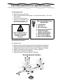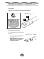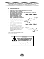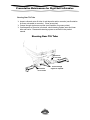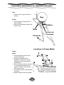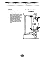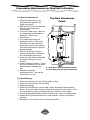
1
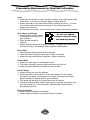
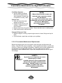
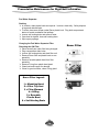
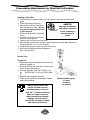
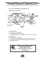
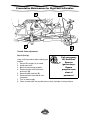
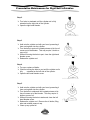
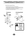
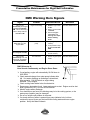
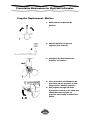
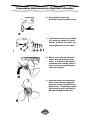
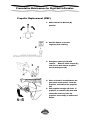
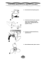
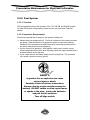
Preventative Maintenance for Rigid Hull Inflatables
2.3.2 Fuel System
2.3.2.1 Overview
The facing page shows the fuel systems of the 733, 630 OB and 590 OB vessels.
For other fuel system configurations, please consult your Hurricane Technical
Manual.
2.3.2.2 Inspection Requirements
Follow these general tips to keep your fuel system working well.
¾ Always keep fuel storage tank full. Fuel level is shown on the console-mounted
fuel gauge. Note that electric fuel gauges are prone to inaccurate readings.
Determine fuel consumption through trials and by monitoring operating time to
accurately determine fuel reserve capacity.
¾ Use the correct fuel (gasoline). With gasoline, make sure to use the correct
octane and gasoline/oil mixture when refueling (check the engine manufacturer’s
technical manual for the right mix).
¾ If your vessel has two fuel tanks, always use the aft tank first. This maintains
your vessel’s optimum center of gravity.
SAFETY:
A gasoline fire or explosion can cause
serious injury or death.
Carefully follow all service instructions.
Always stop the engine and disconnect the
battery. DO NOT smoke or allow open flames
or sparks in the area. Isolate the batteries
and pull the kill switches.
Turn off bilge switch.
69
Preventative Maintenance for Rigid Hull Inflatables
Gas begins to deteriorate after 5 weeks.
Checking for water in shipboard or shorebased fuel storage containers cannot be
stressed enough.
A gas drum has a 3-month life span or less in
shipboard environments due to rust and
condensation.
The fuel octane rating also has a
3-month life span without any gas
stabilizer added to it.
It is imperative to rotate fuel and gas drums
as a part of your preventative maintenance
program. Preventative measures at the
source will help cut down on later fuel
problems.
Fuel Line
Visually inspect the fuel line for cracks, swelling, leaks, hardness, or other signs of
deterioration or damage. If any of these conditions is found, it must be replaced.
Never use gas line antifreeze in any outboard engine. Use Quicksilver Fuel
Treatment and Stabilizer (#92-12253).
SAFETY:
Fuel Oil System
Compartment
Do not use electric
¾ Open Fuel tank void space.
pumps. They can
¾ Inspect top of fuel tank for fuel
produce sparks that can
and clean up any moisture you
ignite gas fumes.
see.
¾ Check void space bilge for fuel
or water. If only water present,
pump out bilge using a hand pump and wipe dry. If fuel oil is present, pump the
bilge water into a waste barrel using a hand pump. Wipe dry.
Fuel Oil Tank
¾ Inspect tank for cracks, leaks, damage or bulging of sides.
¾ Notify the Mate/Coxswain if you find problems.
70
Preventative Maintenance for Rigid Hull Inflatables
Hoses
¾ Inspect all fuel oil hoses for signs of chafing, cracking, nicks, sharp bends, leaks
and/or holes. If you find any damage, replace or repair the hose.
¾ Inspect hose path for any areas where chafing (rubbing) may occur. If you find
such an area, protect the hose by re-routing it, or by putting a protective
wrapping over the area.
¾ Feel the hose for firmness. If a hose feels mushy, replace it as soon as possible.
Hose Clamps and Fittings
Do not over tighten
fittings as they are being
threaded into plastic.
¾ Visually inspect all hose clamps
and fittings to ensure they are in
good condition.
¾ Check all hose clamps for
tightness.
¾ Inspect areas around fittings for signs of leakage. If leakage found, remove hose
and undo the fitting. Re-install the fitting using new thread sealant.
Racor Filters
¾ Visually inspect filter bowls and drain as required.
¾ Check filter bowls for cracks and/or leaks. Repair as required.
¾ Inspect inlet and outlet fittings for tightness. Adjust as required.
Priming Bulbs
¾ Inspect for visible signs of cracking and/or leaks.
¾ Test bulbs by pumping, ensuring that they become and stay firm.
¾ Inspect inlet and outlet fittings for tightness and condition.
Fuel Oil Gauge
¾ Inspect sending unit cover for tightness.
¾ Visually assess the level of the fuel oil tank and compare it to the reading
provided by the gauge. If the gauge is not working, check that it has power
supply (batteries on, breaker panel in good condition).
¾ If the gauge still doesn’t work, check that the wire isn’t broken.
¾ If wiring is in good condition and the power supply is working, the problem may
be in the sending unit. If this is the case, notify the Mate/Coxswain before
proceeding any further.
Engine Connection
¾ Inspect fitting for tightness and condition.
¾ Inspect engine fuel system for leaks and repair as required.
71
Preventative Maintenance for Rigid Hull Inflatables
Fuel Water Separator
¾ Visually inspect both Racor
filters on the outboard’s fuel
vapor separator for water and/
or sediment on a daily basis.
Remote Tank
¾ Check all connections and
NOTE:
If Racor filters are full of water, the
outboard water separators should
also be drained.
If you find a lot of water, drain other
components as well (e.g. fuel pump and
fuel rail on a DFI engine).
See outboard service manual
for details.
clamps for tightness.
¾ Inspect all cap seals for good
condition. Replace if not in
good condition.
¾ Inspect remote hose for good condition. Ensure that there are no chafing marks.
¾ Check that the tank is well secured.
Remote Oil Reservoir Tank
¾ While the engine is running, inspect engine reservoir, hoses, fittings and cap for
leaks.
¾ If you find leaks, repair them and wipe up any spillage.
2.3.2.3 Preventative Maintenance Requirements
Before servicing any part of the fuel system, stop the engine and disconnect the
battery. Drain the fuel system completely. Use an approved container to collect and
store fuel. Wipe up any spillage immediately. Material used to contain spillage must
be disposed of in an approved receptacle. Any fuel system service must be
performed in a well-ventilated area. Inspect any completed service work for sign of
fuel leakage.
SAFETY:
A gasoline fire or explosion can cause
serious injury or death.
Carefully follow all service instructions.
Always stop the engine and disconnect
the battery. DO NOT smoke or allow open
flames or sparks in the area.
Isolate the batteries and pull the
kill switches.
72
Preventative Maintenance for Rigid Hull Inflatables
Filters vary in construction. Consult the manufacturer’s technical manual for
instructions on fuel filter element replacement.
Use the following general procedure:
1. Unscrew the old element from the filter bracket.
2. Coat the sealing ring on the new fuel filter element with engine oil. Thread new
filter element onto the bracket, tightening securely by hand.
3. Run engine and check for leaks.
Fuel Filters
¾ Drain the transom-mounted fuel water separator filter daily.
¾ Drain the water separator filter located on the engine on a weekly basis. When
filter maintenance is done regularly, the engine’s filter should show little or no
water, because the transom filter will have captured it first.
¾ Replace the filter cartridge every 100 hours. Do not rely on a visual water fuel
separation line being obvious on inspection. There may be mostly water in the
inspection bowl, fooling you into believing that it’s fuel.
¾ Drain the bowl into a can and note whether there is water present.
¾ Drain the filter until there is only fuel being discharged.
Change the filter element annually, or as required, depending on local fuel quality.
The newer model fuel-injected engines require the use of fuel conditioners and decarbonizing agents.
¾ Add the fuel conditioner to the fuel after re-fuelling, ensuring that the correct
amount is added for the amount of fuel taken.
¾ Spray the de-carbonizing
agent into the air box at a
Fuel conditioner extends the shelf
given r.p.m. once the
life of the fuel, and reduces the
engine has been warmed
amount of carbon build-up in the
up.
cylinders.
¾ Read the instructions on
the de-carbonizing agent,
The de-carbonizing agent
as each manufacturer
removes most of the carbon
requires a different method
build up.
of product application.
73
Preventative Maintenance for Rigid Hull Inflatables
Fuel Water Separator
Draining
¾ In summer, drain plastic bowls as required. In winter, drain daily. Safely dispose
of rags and drained liquid.
¾ To drain, place save-all pan under Racor plastic bowl. Plug both compartment
drains to contain accidental fuel spillage.
¾ Loosen self-venting drain and remove water.
¾ Once bowl is drained, close self-venting drain.
¾ Wipe up any spillage.
Changing the Fuel Water Separator Filter
Removing the Old Filter
¾ Place save-all pan under filter being changed.
¾ Plug compartment drain holes.
¾ Loosen self-venting drain and drain filter unit.
¾ Remove Racor filter and plastic bowl as one
assembly.
¾ Remove reusable plastic bowl from filter
assembly.
¾ Remove O-ring from plastic bowl gland.
¾ Clean bowl and inspect for damage.
¾ If bowl in good condition, clean O-ring gland.
Racor Filter Legend:
Racor Filter
1
2
3
4
5
1 = Mounting Head
2 = Filter Top Seal
3 = Filter Element
4 = O-Ring
5 = Reusable
Plastic Bowl
6 = Self-Venting Drain
6
74
Preventative Maintenance for Rigid Hull Inflatables
Installing a New Filter
¾ Lubrciate new O-ring with motor oil or light grease, and place in plastic bowl
¾
¾
¾
¾
¾
¾
¾
¾
gland.
Close self-venting drain plug.
SAFETY:
Spin plastic bowl onto new Racor
Improper
installation
filter and tighten by hand. Do not
may cause explosion
use tools to tighten plastic bowl
or fire, resulting in
or filter element.
Fill filter bowl assembly with clean
serious injury or
fuel oil.
death.
Lubrciate top of Racor filter using
motor oil or light grease.
Carefully spin unit only mounting head.
After the filter seal makes complete contact with the mounting head, tighten the
unit an additional 1/3 to 1/2 turn by hand.
Complete priming fuel system and check for leaks.
Wipe up any spillage and safely dispose of
filter, rags and liquid.
1
Remote Tank
Topping Up
¾ Place rags around the filling area to catch any
¾
¾
¾
¾
spilled or dripped oil.
Remove oil-filling cap from each reservoir and
add oil to the required level.
Use only Optimax (1 gal. 92-877694K-1; 2.5
gal.
92-881108K-1; or 45 gal. 92-881109K1).
Reinstall cap and tighten securely.
Clean up any spilled oil and dispose of waste
material as required.
Always double check that
remote oil tank caps are
installed tightly, as any air
leak will prevent oil moving
up to the engine reservoir
tank causing severe engine
damage. Oil can also be
forced into the bilge if remote
tank lids are not secure.
75
2
3
3
1
1
Remote Tank Legend:
1 = Caps
2 = Hose
3 = Clamps
Preventative Maintenance for Rigid Hull Inflatables
Engine Reservoir Tank
Topping Up
¾ Remove cover of each engine.
¾ Visually check oil level in reservoir.
¾ Add oil as required (use the same oil as in
Cap
the remote reservoir). Topping can be
done by just cracking cap loose as engine
is running, allowing air to escape as oil is
pumped in by engine system.
¾ Tighten fill cap.
¾ Note: New engines might not have a full
tank, as they are shipped from the factory half full. The oil alarm will sound when
the engine is started for the first time.
SAFETY:
Always double check that the
engine oil tank cap is installed
tightly, as any leak will cause oil
spillage. Oil spillage may cause
an engine fire.
SAFETY:
Always clean up any fuel
spills immediately.
Dispose of liquid and rags safely.
Wait until fumes dissipate before
starting the engine.
76
Preventative Maintenance for Rigid Hull Inflatables
2.3.3 Gauges and Wiring
2.3.3.1 Inspection Requirements
Inspect all gauges and wiring for broken wires, loose connections and/or faulty
gauges every day.
2.3.3.2 Preventative Maintenance Requirements
Gauges
¾ It is common for some 733s to have a bit of moisture in their gauges. The
moisture usually goes away once they get warm.
¾ A few inaccurate tachometers have been noticed in the fleet. The maximum
r.p.m. for an EFI 150 is 5600 and 5750 for DFI Optimax engine.
¾ To check the accuracy of your tachometer, you will need the Digital Diagnostic
Terminal (DDT) hooked up to your engine. Compare the true r.p.m. from the
DDT with what your tachometer gauge indicates at various r.p.m. ranges.
¾ If there is a discrepancy, go with the DDT as the true r.p.m. reading.
¾ Check the true r.p.m. against the recommended r.p.m. for your propeller. If
necessary, change the propeller to one with a lower pitch.
77
Preventative Maintenance for Rigid Hull Inflatables
Wiring
Salt water is wiring’s worst enemy. The most common problems include corrosion
on terminals, loose connections, rotten wires (i.e. burnt, green, and/or abandoned
wires that weren’t taken out properly the first time).
¾ Inspect all wiring components thoroughly. When in doubt, change the
¾
¾
¾
¾
component to ensure that all contacts are free of corrosion.
Make sure that:
1. All contacts are tight and have proper nuts (brass, not steel).
2. There is no excessive moisture in the contacts.
3. Proper gauge of wire is used for the right application, to reduce the
possibility of chafing.
4. All breaks have waterproof boots on them and the proper Amp rating for
the application.
Use Ship to Shore and dielectric grease or Merc corrosion guard (92-827933 55)
on all exposed wiring and electrical components.
Keep all wires neatly tie wrapped together.
Become familiar with the electrical system and know all the related components
and their functions. Knowing the system will help you trouble-shoot future
problems.
If you do these basic procedures on a regular basis, there is less chance of
something failing. It will also help you find a problem and fix it before it becomes
something major (short circuit = chance of a fire).
SAFETY:
It is known that some people have
replaced breakers with a larger amp
rating than required.
This could cause a short and a fire.
Contact the Officer-in-Charge of
Inflatable Craft Maintenance before
replacing a breaker with one of a
larger amp rating.
78
Preventative Maintenance for Rigid Hull Inflatables
2.3.4 Corrosion Control Anodes
2.3.4.1 Overview
Anodes help to protect your engine against corrosion. They allow their metal to be
slowly eroded instead of the metal of the outboard itself.
Each outboard has three corrosion anodes,
located as follows:
¾ Two at the sides, just above the trim tab (a
and b) (one on OMC engines).
¾ One at the bottom of the transom bracket
(c).
Hulls also have anodes located on the transom.
2.3.4.2 Inspection Requirements
¾ Inspect the anodes for erosion and replace if
less than 3/4 (75%) of original size.
¾ If you replace the trim tab anode, be sure to
install the new unit in the exact same
position.
¾ Check that all anodes are securely fastened.
¾ Ensure that none of the anodes are painted
or covered with a protective coating. If an
anode is coated over, remove the paint or
coating immediately.
MERC Outboard
a
2.3.4.3 Preventative Maintenance
Requirements
c
¾ Replace anodes at 50%.
¾ Never paint over anodes.
¾ Clean area before replacing zincs and
anodes.
OMC Outboard
79
Preventative Maintenance for Rigid Hull Inflatables
2.3.5 Propeller
2.3.5.1 Overview
WARNING:
Propellers don’t require much care, but you do
need to check them daily to maintain vessel
performance.
Never repair propellers in
the field, as you can cause
more damage.
2.3.5.2 Inspection Requirements
¾
¾
¾
¾
Visually inspect the propellers for damage.
If the damaged area is larger than a dime, replace the propeller.
Inspect the propeller shaft to ensure that it is straight.
If using flow-torque hubs, re-torque the hubs after a good run (55 ft. lbs. of
torque).
1
1.
2
This propeller has thrown a blade because a
very small nick has not been repaired and it
has gradually cracked and blown off.
2.
Note:
This propeller has hit a very hard object and
may be out of balance even after extensive
repairs. It should be replaced.
Cavitation is damage caused by air
bubbles as the propellers race through
the water.
80
Preventative Maintenance for Rigid Hull Inflatables
2.3.6 Outboard Motor Controls
2.3.6.1 Inspection Requirements
Controls
¾
¾
¾
¾
Check 2 control base securing screws for tightness—see diagram below (a).
Check 2 control handle mounting brackets—see diagram below (b) .
Check 2 nylon locknuts—see diagram below (c).
Ensure all electrical connections are tight and the harness is properly secured
and out of the bilge.
¾ Check controls for ease of operation. If controls require increase in effort to
move, investigate the cause. Do not force controls (check control and engine
end for binding).
¾ Repair and lubricate the unit using Quicksilver 2-4-C Marine Lubricant.
a. Screw (10-32X4.00 (2)
b. Mounting Bracket (2)
c. Nylon Locking Nut 10-32 (2)
81
Preventative Maintenance for Rigid Hull Inflatables
Steering System Oil
¾ Remove helm pump filler plug.
¾ Helm units are mounted at 20 degrees. The oil level should be ½” (12.7 mm)
from the hole.
¾ If oil level is below required
level, top up. Use same oil as
presently in the system. See
box for recommended oils.
Recommended Steering
System Oils
1.
2.
3.
4.
5.
Texaco H015
Shell Aero 4
Esso Univis N15
Chevron Aviation Fluid A
Fluids Meeting Mil
H5606c Specifications
6. Teleflex Steering Fluid
7. Power Steering Fluid
8. Sea Star Fluid #HA5430
WARNING:
Never use brake fluid. It
may cause irreparable
damage and loss of
steering.
Steering Gear Fasteners
On a weekly basis:
¾
¾
¾
¾
¾
¾
Physically inspect all steering gear fasteners and linkages for tightness.
Tighten all loose fasteners and replace any damaged or missing parts.
Wiggle all ball joints to check for excessive wear. Replace as required.
Inspect 4 nuts securing the help pump. Check for tightness.
Inspect helm-securing nut for tightness.
Inspect all hydraulic lines and fittings for tightness.
Steering System Fasteners
82
Preventative Maintenance for Rigid Hull Inflatables
Tie Bar System
Check for overall condition of steering system and components.
Tie Bar System
1
SAFETY:
The threaded rod must always
fully cover Inspection Hole 1,
but NEVER Inspection Hole 2
(see right). Failing to observe
this warning may result in one
engine being separated from
the steering system, resulting
in property damage and/or
personal injury.
2
Steering Gear Cylinder Shafts
A) Visually inspect the cylinder shafts for
damage.
¾ Look for large nicks, scouring, flaking of
metal, gouges, loose connections or
bends in the unit.
¾ Inspect shaft for salt water corrosion. A
rough or damaged shaft will cause seal
damage and oil loss. Tell the Mate/
Coxswain about damage.
83
Cylinder Shaft Damage
Nicks
Gouges
Flaking
Preventative Maintenance for Rigid Hull Inflatables
B) Visually inspect the seals
¾ Inspect seals in place for damage (small tears, pieces missing).
¾ Inspect the seal area for oil leakage.
¾ Have one person turn the helm to port. Apply enough force to exceed relief
valve pressure. Maintain pressure.
¾ Second person should fully inspect
extended cylinder shaft. If minor
damage is found, polish area using
Brasso. Clean polished area thoroughly
with solvent after completion. Wipe with
steering fluid.
¾ At the same time, the second person
should inspect the shaft for leaks and/
or damage.
¾ Tell the Mate/Coxswain if a seal is
leaking. Replace the seal or unit as
soon as possible.
¾ Check oil reservoir for correct fluid
level. Add as required. If a seal is
replaced or reservoir empty (low), bleed
the steering system. Wipe up any oil
around the steering cylinder upon
completion.
Leak in Way of Seal
Leak in Way of Seal
Then repeat the procedure again, with the
helm turned to starboard.
WARNING:
Using a steering system with leaking
seals or badly damaged shafts may
result in the complete loss of oil.
This can cause steering failure
resulting in property damage and/or
personal injury.
84
Preventative Maintenance for Rigid Hull Inflatables
Steering Gear Tilt Tube
¾ Inspect outboard motor tilt tube for salt deposits and/or corrosion (see illustration
for areas vulnerable to corrosion). Clean as required.
¾ Grease through nipples as required (see illustration for grease points).
¾ If salt deposits or corrosion is extreme, unbolt steering system arms and clean
tube and carrier. Reassemble steering system as outlined in the product
manual.
Steering Gear Tilt Tube
Check here
for corrosion
Check here
for corrosion
85
Grease through
nipples as required.
Preventative Maintenance for Rigid Hull Inflatables
2.3.6.2 Preventative Maintenance Requirements
Check Shift Cable Adjustments
Shift Cable
Retainer
Cable Barrel
Cable End
Guide
A) Remove Propeller
1. With remote control in Forward.
2. The propshaft should lock solidly in gear.
3. If the propshaft does not lock, adjust cable barrel closer to cable end guide.
B) Increase Gap
1.
2.
3.
4.
Shift remote control into Neutral.
The propeller shaft should turn freely in either direction without any drag.
If any drag is present, adjust cable barrel away from cable end guide.
Repeat Steps A and B.
Pull emergency Kill Switches.
Remove ignition keys.
Ensure propeller area clear
of personnel.
86
Preventative Maintenance for Rigid Hull Inflatables
C) Decrease Gap
1. Shift remote control into Reverse (turn shaft while checking propeller shaft for
movement).
2. The propshaft should lock solidly in gear.
3. If shaft does not lock, adjust barrel away from cable end guide.
4. Repeat steps A through C.
D) Increase Gap
1.
2.
3.
4.
Shift remote control into Neutral.
The propeller shaft should turn freely in either direction without any drag.
If any drag is present, adjust the barrel closer to cable end guide.
Repeat steps A through D.
Pull emergency Kill Switches.
Remove ignition keys.
Ensure propeller area clear
of personnel.
87
Preventative Maintenance for Rigid Hull Inflatables
A
C
D
B
Throttle Cable Adjustment
Step A (Set-up)
Carry out this procedure before starting the
engines.
1.
2.
3.
4.
5.
6.
7.
8.
Pull emergency
Kill Switches.
Remove
ignition keys.
Ensure
propeller area
clear of
personnel.
Secure RHI properly in its cradle.
Install water muff.
Block off area around propeller.
Remove throttle cable from lever
anchor pin (B).
Remove cable retainers (D).
Remove throttle cable barrel from
receptacle.
Turn on water supply.
Check to make sure the propeller area is clear of people or foreign objects.
88
Preventative Maintenance for Rigid Hull Inflatables
Step B (Testing)
1. Start engine being tested. Ensure good water discharge.
2. Warm up engine.
3. Adjust engine RPM to 600-700 RPM in forward gear. Never increase RPM
above 750, or you will damage the engine.
4. Shift control lever into Neutral.
5. Reattach cable end to throttle lever anchor pin and secure with latch (B).
6. With the throttle cable attached to the throttle lever, hold throttle lever against
idle stop (C).
7. Adjust throttle cable barrel. It should slip into the barrel receptacle (A) with a
very light pre-load of throttle lever against the idle stop (C). A piece of paper
should drag through, but not tear.
8. Lock barrel back into place using cable retainer.
Block off area around propellers.
Visually inspect area around
propellers for foreign objects.
Have one crew member stand by
to ensure nothing goes near
the propellers.
Step C (Pre-Load Check)
1. Place a thin piece of paper (C) between the idle stop screws and idle stop.
2. If the pre-load is correct, the paper can be removed without tearing, only feeling
a slight drag.
3. If the paper tears, or if there’s drag present, readjust the barrel.
Do not try to synchronize
control head shift handles
by adjusting the throttle
and shift cables, or any
screws at the engine.
Too much pre-load
creates an unnecessary
strain on the
control cable.
Throttle adjustments must
be re-checked once the
vessel is afloat.
Readjust as necessary.
89
Preventative Maintenance for Rigid Hull Inflatables
Controls
Repair and lubricate the unit using Quicksilver 2-4-C Marine Lubricant.
Lubricating Points on Control Cable
Remote Control
This illustration depicts an
OMC-type control cable.
Adjusting Barrel or Knurl
Engine End
SAFETY:
If you don’t tighten set screws, handles
may disengage, causing a loss of
throttle shift control.
To prevent shorts, make sure that all
connections are secure and have been
lubricated with dielectric grease.
90
Preventative Maintenance for Rigid Hull Inflatables
Steering System Bleeding
This operation requires two people. One at the helm and
one at the cylinder.
Step 1
¾ Remove steering reservoir cap.
¾ Install threaded end of filler tube into reservoir filler hole
(helm).
¾ Remove lid from oil bottle. Use only recommended
¾
¾
¾
¾
oils—see below.
Holding bottle upright, screw it into the filler tube bottle cap.
Turn bottle upside down and punch a small hole into the bottom of bottle.
Fill reservoir full of oil (make sure oil is always visible in the filler tube).
If the level falls off, stop immediately and install a new oil bottle.
WARNING:
If the oil level gets
too low, more air will
be sucked into the
system and you
must start the
bleeding process
again.
Recommended Steering
System Oils
1.
2.
3.
4.
5.
Texaco H015
Shell Aero 4
Esso Univis N15
Chevron Aviation Fluid A
Fluids Meeting Mil H5606c
Specifications
6. Teleflex Steering Fluid or
7. Power Steering Fluid
8. Sea Star Fluid #HA5430
91
Preventative Maintenance for Rigid Hull Inflatables
Step 2
¾ Turn helm to starboard until the cylinder rod is fully
extended on the right side of the cylinder.
¾ Open the right hand bleeder.
Step 3
¾ Hold onto the cylinder rod with your hand, preventing it
from moving back into the cylinder.
¾ Turn the helm to port until a steady stream of air-free oil
comes out of the bleeder. This may require ½ bottle or
more of oil.
¾ While still turning the helm to port, close the right hand
bleeder screw.
¾ Release the cylinder rod.
Step 4
¾ Top up or replace oil bottle.
¾ Continue turning the helm to port until the cylinder rod is
fully
extended on the left side of the cylinder.
¾ Open the left hand bleeder screw.
Step 5
¾ Hold onto the cylinder rod with your hand, preventing it
from moving back into the cylinder.
¾ Turn the helm to starboard until a steady stream of airfree oil comes out of the bleeder. This may require ½
bottle or more of oil.
¾ While still turning the helm to starboard, close the left
hand bleeder screw.
¾ Release the cylinder rod. Remove the oil bottle, filling
tube and reinstall reservoir cap.
¾ Clean up any spilled oil.
92
Preventative Maintenance for Rigid Hull Inflatables
Cylinder Slider Cleaning and Greasing
¾
¾
¾
¾
¾
¾
Clean slider assembly of any dirt. Wipe off old grease.
Inspect all fasteners (see illustration) for tightness and good working order.
Grease all fasteners using Quicksilver 2-4-c, OMC Triple Guard or equivalent.
Thoroughly grease the slider assembly (see illustration).
Turn helm hard to Port and Starboard several times to work in the grease.
Inspect sliders. Grease further if required.
Fasteners
Greasing Points
WARNING:
Slider assembly
must always
be greased.
Do not operate the
boat if the slider
assembly
is dry and
free of grease.
93
Preventative Maintenance for Rigid Hull Inflatables
2.3.7 Kill Switches
2.3.7.1 Overview
The purpose of the Kill Switch is to turn off (kill) the engine when the operator falls
off the deck or moves far enough away from the operator’s position to activate the
switch (accidental ejection).
2.3.7.2 Inspection Requirements
For both Mercury and OMC Kill
Switches
Mercury Kill Switch
¾ Inspect lanyard clasp for good
¾
¾
¾
¾
working condition.
Ensure lanyard rope is not frayed
or damaged in any way.
DO NOT add any length to the
factory-supplied lanyard.
Pull on lanyard to check that it is free to pull
off Kill Switch.
Ensure that lanyard is not too long. It
should pull out if you fall to the deck.
OMC Kill
Switch
SAFETY:
DO NOT run an engine
with a faulty kill switch.
94
Preventative Maintenance for Rigid Hull Inflatables
2.3.7.3 Preventative Maintenance Requirements
Testing
For both Mercury and OMC Kill
Switches
Mercury Kill Switch
¾ While the engine is running, pull the
Kill Switch for that engine.
¾ Engine should come to an
immediate stop.
¾ Reinstall lanyard and re-start
engine to verify that lanyard is
properly re-installed.
¾ Shut down motor via ignition key.
¾ Start second motor and follow the
above procedure again.
Tell the Mate/Coxswain if
engine does not shut down
when the lanyard is pulled
(Kill Switch released).
Further investigation should
be done immediately.
Check to ensure that the
switch is free and
not seized.
Toggle several times.
OMC Kill
Switch
Warning:
¾
¾
¾
¾
¾
If starting engines while RHI is onboard ship,
check the following:
Engine muffs properly installed and water
supply on.
All personnel informed that engines will be
started.
Area around propellers blocked off or access
denied.
Propeller areas clear of objects or personnel.
Control in “Neutral” position.
95
Preventative Maintenance for Rigid Hull Inflatables
2.3.8 Warning Horns
2.3.8.1 Overview
Canadian Coast Guard/Department of Fisheries and Oceans rigid hull inflatables are
equipped with propulsion systems that use a system of warning horns. When a
problem is detected, the warning horn sounds. Your system may also be equipped
with a visual display.
The horn will sound continuously if the problem can cause immediate engine
damage. The horn will sound intermittently if the problem will not cause immediate
engine damage.
2.3.8.2 Inspection Requirements
For both Mariner and OMC, test the warning horns regularly as follows:
¾ Turn on battery isolation switch.
¾ Turn ignition key from OFF to ON.
¾ The warning horn will beep once as a selftest.
¾ Repeat steps for the other outboard motor.
¾ If the alarm fails to beep, tell the Mate/
Coxswain.
NOTE:
The alarm on the MERC model
year 1999-2000 side-mount
controller will NOT sound
when the key is in the ON
position prior to starting.
Each type of engine has its own signals. If you hear the warning horn, check
these charts to see what it means, and follow the steps.
Mariner Warning Horn Signals
Signal
Problem
Horn sounds continuously.
Engine overheating.
Immediate Action
¾
¾
¾
Horn sounds
intermittent short beeps.
Low level in the injection
system.
Reduce engine RPM to
idle.
96
See Marine Reference #1
Return control handle to
Neutral.
Wait until engine cools
down and warning
horn stops before
shutting down.
Stop engine.
Oil injection pump failure
Reference
See Mariner Reference #2
Preventative Maintenance for Rigid Hull Inflatables
Mariner Reference #1
Horn Sounds Continuously (Engine Overheating)
¾ Check water discharge from water pump indicator hole (A).
¾ If no water discharge or discharge is intermittent, stop the
¾
¾
¾
¾
¾
engine(s). Pull Kill Switch on engine being checked. Tilt
up engine.
A
Check cooling water intake holes for obstruction.
Remove any obstruction found. Lower engine and re-start.
Monitor engine water discharge. If no obstructions are
found, the blockage may be in the cooling system or the water pump (impeller)
may be damaged.
Do not run engine until the problem is corrected.
If a steady stream of water is present from pump indicator hole, but the horn
continues to sound, there may be insufficient cooling water or an engine
problem. Notify the Mate/Coxswain.
If you are stranded, you can stop the engine and allow it to cool back
down. This will give you some additional low speed (idle) running
time before the engine overheats again.
Do this procedure only in an emergency as engine damage may result.
Mariner Reference #2
Horn Sounds Intermittent Short Beeps (Low Oil)
¾ On EFI, DFI Outboards, intermittent beeps can indicate water in the engine’s fuel
¾
¾
¾
¾
¾
¾
¾
water separator. A red light in front of the engine will also indicate that water is
present in the fuel separators. If this occurs, drain the fuel water separators.
Stop engine. Pull Kill Switch on engine being
checked.
Remove top cowl.
A
Check oil level in engine-mounted reservoir.
If the oil level is below the top of the tank, the
problem is low oil (A).
Check the remote reservoir to verify that it is
empty. If the remote tank is full, check filler
caps for tightness and hoses to ensure no air
leaks. Bleed system before operating again.
If the engine-mounted reservoir tank is full, the problem may be the oil injection
pump.
Do not run the engine unless it can be run using a remote tank with a 50:1
gasoline/oil mix. If engine is run without oil, severe damage will result.
If alarm sounded because oil is low, you can still operate the vessel for
approx. 30 min. Keep close track of the oil level.
If the engine oil runs out, severe motor damage will result.
97
Preventative Maintenance for Rigid Hull Inflatables
OMC Warning Horn Signals
Signal
Problem
Horn sounds
continuously and engine
will not exceed 2500
RPM. This is caused by a
built-in safety featured
called S.L.O.W.
Engine overheating.
Horn sounds rapid, short
tones that vary with
engine RPM.
No oil flow from the oil
pump.
Horn sounds one short
tone every 40 seconds.
Low oil level in oil tank.
Horn sounds
continuously at or neat
full throttle, but engine
speed not effected.
Fuel restriction.
Immediate Action
¾
Reference
Reduce engine RPM
to idle.
Return control handle
to Neutral.
Wait until engine
cools down and
warning horn stops
before shutting
down.
See OMC Reference #1
Stop engine (best
solution).
If not possible to stop,
do not exceed 1500
RPM.
See OMC Reference #2
¾
Refill oil tank (tank
level at reserve).
See OMC Reference #3
¾
Reduce engine speed
to idle.
See OMC Reference #4
¾
¾
¾
¾
OMC Reference #1
Horn Sounds Continuously and Engine Slows Down
¾ If overheating, engine will automatically SLOW down to
2500 RPM.
¾ Check water discharge from water pump indicator hole
¾
¾
¾
¾
¾
¾
A
(A). If no water discharge or discharge is intermittent,
stop engine(s). Pull Kill Switch on engine being
checked. Tilt up engine.
Check cooling water intake holes for obstruction.
Remove any obstruction found. Lower engine and re-start. Engine must be shut
down (ignition key OFF) to re-set SLOW function.
Monitor engine water discharge.
If no obstructions are found, the blockage may be in the cooling system, or the
water pump (impeller) may be damaged.
Do not run engine until problem is corrected.
If a steady stream of water is present from pump indicator hole, but horn
continues to sound, there may be insufficient cooling water and/or an engine
problem. Notify the Mate/Coxswain.
98
Preventative Maintenance for Rigid Hull Inflatables
In an emergency, you can stop the engine after allowing it to cool
down. Once the alarm stops, shut off the ignition switch and re-start
the engine. This re-set SLOW function will give some additional low
speed (idle) running time before the engine overheats again.
Do this only in an emergency, as engine damage may result.
OMC Reference #2
Horn Sounds Rapid Short Tones That Vary With Engine Speed
¾ This is an indication that there is no oil flow from the pump.
¾ Problem may be no oil in reservoir or failure of the injection oil pump.
¾ Inform the Mate/Coxswain and carry out any repairs required before running the
engine.
OMC Reference #3
Horn Sounds One Short Tone Every
40 Seconds
¾ Oil reservoir level is at
approximately ¼ tank.
¾ Refill as soon as possible.
¾ Reserve gives you approximately
SAFETY:
Severe engine
damage will result if
the engine is run
above 1500 RPM
without a 50:1 fuel/oil
mixture.
30 minutes at maximum RPM, but
tank should be filled as soon as
possible.
¾ If tank is run dry, system must be purged of air before being put back into
service.
OMC Reference #4
Horn Sounds Continuously At Or Near Full Throttle
¾ If the alarm horn stops when RPM is reduced, a fuel restriction is present. If
alarm continues, see OMC Reference #1.
¾ The engine should be operated at reduced speed and the vessel should return to
base.
¾ Inform the Mate/Coxswain.
¾ Inspect F/O filters and clean as required. If problem continues, contact Inflatable
Craft Maintenance.
WARNING:
Don’t run on your reserve oil. Completely running out of oil
can result in severe engine damage.
99
Preventative Maintenance for Rigid Hull Inflatables
2.3.9 Trouble-Shooting and Repairing Your
Outboard Motor
2.3.9.1 Overview
Consistency and attention to detail are essential elements of outboard motor
maintenance. You must have the User and/or Service Manual to do proper repairs.
¾ Step 1—Get the right manuals.
¾ Step 2—Do the maintenance!
The horsepower and types of outboard engines used by the Department of Fisheries
and Oceans vary greatly. Instead of looking at specific engine models, this section
covers the similarities in all of the engines. As engine technology advances, so
does the equipment required to diagnose the engine’s operation. There are very
few components used in the construction of new user-friendly (adjustable/repairable)
outboard engines. Most engine components are go/no go components, requiring
replacement rather than repair.
You can fix most common problems in the field with a little common sense and a
service manual. A technician is needed to repair or trouble-shoot more complex
problems. It is embarrassing to take an outboard to a shop and say it doesn’t start
only to find out that the kill switch was activated, or it was running rough and a spark
plug wire was loose or completely off. Basic problems like these have happened
and they cost the Coast Guard time and money.
2.3.9.2 What To Do If Your Engine Won’t Start
Mercury Mariner (EFI and Opti/Max DFI) Engines (2.5L) and Mercury
Mariner 90 HP
Typical failures on these engines do not involve the electric control module (ECM),
but connections, set-up and mechanical wear. Batteries must have a cranking
voltage of 9.5 volts or higher at the starter. Low battery voltage can cause the oil
and fuel pumps to malfunction.
¾
¾
¾
¾
¾
Check all fuses.
Make sure all spark plug leads are pushed in all the way.
Check to see that the fuel pump filter is clean.
Ensure that the water separating fuel filter is full.
Check to see that the racor filters are on full (is there water present?). If you
suspect an onboard fuel problem, run the engine on a day tank to see how it
runs. This can rule out many components.
¾ Consult the EFI or DFI Service Manual for more trouble-shooting details.
¾ Check that control handles are in the Neutral position and that the kill switches
haven’t been thrown.
100
Preventative Maintenance for Rigid Hull Inflatables
2.3.9.3 Digital Diagnostic Tool (DDT)
Most stations and ships have access to the Quicksilver Digital Diagnostic Tool
(DDT). With a DDT, you are able to monitor sensors and electronic control module
(ECM) data values, including status switches.
The ECM program can help diagnose intermittent engine problems. It records the
state of engine switches and sensors over a period of time and can be played back
for review later. When used correctly, the DDT can be a valuable trouble-shooting
tool. If used incorrectly, it can add to the problem.
Remember the basics and keep it simple. Refer to the Quicksilver Technician
Reference Manual for further testing and operational procedures.
DDT Basics
The DDT allows you to:
¾ Record and view real-time system data.
¾ Perform static tests on some engines (DFI 150, EFI 150).
¾ Read past history of failures or faults and passes which are retained by the
ECM.
¾ See details broken down to separate components:
1. Ignition
2. Injector
3. Pump
4. Sensors
5. Switches
6. Misc.
7. RPM limit
8. Break-in time and system info.
¾ Compare data values to the manufacturer-recommended specs outlined in the
Service Manual to hone in on engine problems.
2.3.9.4 The Onboard Fuel System
This section covers only a few of the most common problems. If any one of the
basics fails, fix that problem first, then continue. Contaminated fuel is a problem.
The EFI and DFI engines do not like water or other foreign objects (i.e. rust from old
gas drums) mixed with the fuel. Any of these can cause trouble for the engines.
Proper filtration, checking for water and age of fuel are all very important.
Always consult your engine manufacturer’s technical manual for details when
trouble-shooting the engine.
101
Preventative Maintenance for Rigid Hull Inflatables
If fuel delivery to the engines is being restricted, then the primer bulbs (located in the
aft machinery space) will be soft or collapsed.
It is more difficult to diagnose restricted fuel delivery. Follow these steps:
1. Check fuel level in both tanks.
2. Ensure that fuel selector valves are correctly aligned with the fuel tank selection
indicator.
3. Check fuel tank vents for kinks or blocking.
4. Remove deck fill caps. If this corrects the problem, fuel storage tank vents are
suspect. For fuel storage tank vent trouble-shooting, contact the Inflatable Craft
Maintenance shop in Victoria.
5. Check fuel supply hoses for kinks.
6. Check fuel return hose for kinks (inboard engine only).
7. Replace water separating fuel filter element.
8. Check fuel tank supply fittings for blockage.
9. Pick-up screens may be blocked.
102
Preventative Maintenance for Rigid Hull Inflatables
Propeller Replacement—Mariner
1. Shift outboard to Neutral (N)
position.
2. Pull Kill Switch(s) to prevent
engine(s) from starting.
2
3. Straighten the bent tabs on the
propeller nut retainer.
nut
4. Place a block of wood between the
gear case and the propeller to hold
the propeller. Remove propeller.
5. Pull propeller straight off shaft.
If propeller is seized to the shaft and
cannot be removed, have the
propeller removed by an authorized
dealer.
103
Preventative Maintenance for Rigid Hull Inflatables
6. Coat propeller shaft with
Quicksilver Anti-Corrosion Grease.
7. Install thrust washer (a), propeller
(b), continuity washer (c), thrust
hub (d), propeller nut retainer (e),
and propeller nut (f), onto shaft.
8. Before you torque the nut down,
ensure that the propeller spins
freely. It should not rub against
the bottom end housing. Place a
block of wood between the gear
case and propeller.
9. Secure propeller nut by bending
three of the securely tightened
propeller nut tabs into the thrust
hub grooves. Torque the propeller
nut to factory specs (55 ft/lbs for
EFI and DFI Optimax Mariner).
104
Preventative Maintenance for Rigid Hull Inflatables
Propeller Replacement (OMC)
1. Shift outboard to Neutral (N)
position.
2. Pull Kill Switch to prevent
engine(s) from starting.
2
3
3. Straighten cotter pin (D) and
remove.
Remove index keeper (E),
then loosen and remove propeller
nut (C) and spacer (B).
4. Place a block of wood between the
gear case and propeller. Hold the
propeller and remove the propeller
nut.
5. Pull propeller straight off shaft. If
propeller is seized to the shaft and
cannot be removed, have the
propeller removed by an authorized
dealer.
105
Preventative Maintenance for Rigid Hull Inflatables
6. Coat the shaft with spline grease.
7
7. Install thrust bushing (A), propeller
spacer (B), engaging propeller
shaft splines. Finally install the
propeller nut (C).
8. Torque to recommended factory
specifications.
9. Use stainless cotter pins to secure.
106
Preventative Maintenance for Rigid Hull Inflatables
Steering System Oil Loss
If you find oil loss during inspection, investigate the cause and repair.
¾ Check bilges for oil and clean up any oil found.
¾ Ensure engines free to turn (no restrictions on deck, etc.).
¾ If any major repairs required (i.e. hose replacement, seals, etc.), immediately
bleed the system of air and top up.
1. Turn helm hard to port, applying enough force to exceed
relief valve pressure.
2. While one person maintains helm pressure, the second
person should carry out the inspection.
3. Inspect the following for leaks or seepage:
¾ Helm pump unit (around shaft, casing and filler
tube).
¾ Hose connections and fittings at helm pump.
¾ Hoses for seepage (hose feels like it is saturated
in oil).
¾ Hose fittings and connections at steering cylinder.
¾ Check cylinder end seal of ram in the out position.
4. Helm hard to port. Ensure bleed screws completely
closed.
Repeat with the helm held hard to starboard.
Repair all leaks immediately, wiping up any spilled oil.
Keep a close eye on all repairs to ensure that they are
carried out properly. Inform the Mate/Coxswain of any
major problems (i.e. leaks at seals or worn/holed hoses).
107
Preventative Maintenance for Rigid Hull Inflatables
108
Preventative Maintenance for Rigid Hull Inflatables
2.4 Self-Righting System
2.4.1 Overview
Although RHIs are inherently very stable, many have an optional self-righting
system. In a capsize situation, the self-righting system enables the operator to right
the boat. Detailed operating instructions are contained in the Hurricane Technical
Manual and RHIOT Manual.
The system has four main parts:
¾
¾
¾
¾
An inflatable self-righting bag.
A compressed air cylinder.
A firing head/fill assembly.
A self-righting (aluminum) frame.
The inflatable self-righting bag is made of an external layer of Hypalon, a core of
either nylon or polyester fabric, and an internal layer of neoprene rubber. It is bolted
with aluminum flanges to a tray at the top of the self-righting frame. A fabric valise
covers and contains the folded self-righting bag. The valise closure is velcro that
automatically releases as the bag inflates.
The compressed air cylinder is attached to the self-righting frame. The firing head
threads into the cylinder.
The self-righting system is designed to operate manually, not automatically. A
handle located on the transom activates the system. This handle is attached to a
firing head via a release cable, enabling the operator to activate the system from the
water. When the release cable exits the firing head, a spring loaded bayonet
pierces the puncture disc, located in the cylinder head. The high-pressure gas fills
the self-righting bag.
The self-righting frame houses the entire system and provides the height necessary
for the inflated self-righting bag to right the boat. The frame is mechanically
attached to the deck and/or transom. There is a small platform for navigation lights.
Variations to the frame model include:
¾
¾
¾
¾
Larger platform for radar antenna mounting (optional).
Folding frame for air transport or storage (optional).
Integral tow bollard.
Tow reel and attachments.
The structural strength of the self-righting frame is very critical, as any weakness
may cause it to tear away from the deck when the vessel overturns, or once the selfrighting system is deployed. If this happens, it will prevent the vessel from righting
itself, possibly causing further damage to the vessel and injury to the operator and/or
crew.
109
Preventative Maintenance for Rigid Hull Inflatables
Self-Righting System
2.4.2 Inspection Requirements
General
Inspect the self-righting system weekly.
1. Inspect exposed areas of the self-righting bag for signs of wear and tear,
chafing, visible rips or puncture holes and signs of wear around the mounting
flange.
2. Inspect the clamps that secure the compressed gas cylinder for tightness.
3. Check the firing head/fill assembly for:
¾ Valve tightness.
¾ Banjo tightness.
¾ Fill hose tightness (both ends) and kinking or chafing.
¾ Firing head tightness.
¾ Firing cable handle attachment snap corrosion.
4. Inspect the self-righting frame for:
¾ Attachment bolt tightness.
¾ Fatigue cracks in aluminum, particularly near welds.
¾ Hinge and latch mechanisms (if applicable).
110
Preventative Maintenance for Rigid Hull Inflatables
Conduct a Bag Inspection and Air Retention Test monthly as follows:
Step 1—Inspection
¾
¾
¾
¾
¾
¾
¾
Install cylinder maintenance safety pin.
Undo the velcro to open the valise.
Remove debris and clean.
Visually inspect the bag for large tears or obvious damage.
Inspect corners of the bag where it is folded (one side at a time).
Make sure there is no loose fabric or areas lifting on the bag.
Inspect all exposed areas of the bag for chafing or extreme wear or damage
(check this weekly).
¾ Repair any damaged areas as outlined in the manual.
¾ Proceed to Air Retention Test (see next page).
Air Retention Test Sheet for Self-Righting Bag
111
Preventative Maintenance for Rigid Hull Inflatables
Step 2—Air Retention Test
While the bag is installed on the frame:
¾ Replace the relief valve with a plug.
¾ Remove the cylinder outlet hose.
¾ Inflate the bag with bellows until the pressure relief valve activates. Ensure
pressure relief re-seals.
¾ Replace the fill valve cap securely.
¾ Allow the bag to sit for about 1 hour, giving the pressure time to stabilize (to the
surrounding temperature).
¾ After the bag has acclimatized, adjust the air pressure back to 3 psi (remove or
add air as required).
¾ Measure the air pressure and enter it next to “Start” on the test sheet (see
previous page).
¾ Take the ambient air temperature and the barometric pressure, and note them
on the same line of the test sheet.
¾ Wait an additional hour. Re-test the bag’s air pressure and enter next to “End”
on the test sheet.
¾ Take a second reading of the ambient air temperature and barometric pressure
and enter these next to “End” on the test sheet.
¾ If there is a pressure difference, you have a leak and you must find it.
¾ With the bag still inflated, mix up a water/soap solution.
¾ Using a paintbrush, paint the solution over the bag, including all seams and
¾
¾
¾
¾
¾
¾
¾
¾
¾
valves.
The leaks will be seen as a growing chain of bubbles.
If the hole is large, you may even hear the air escaping.
Repair leaks as per the chart in the Trouble-Shooting and Repair Section 2.4.4..
After you’ve repaired the leaks, rinse, dry and re-coat with Protectant 303.
Once all leaks have been repaired, remove all air from the bag.
Remove plug and reinstall relief valve.
Calculate compensation pressures using: .03 psi per degree and .49 psi per
inch of mercury.
Deflate and re-fold, back over front to ensure proper inflation.
Centralize bag in cradle; fold front over first, then fold the back over top of the
front fold. This ensure that bag inflates toward the stern. If the bag inflates
forward it may not have enough lift to take the vessel over its center of gravity.
112
Preventative Maintenance for Rigid Hull Inflatables
Cylinder and Firing Head
¾ Visually inspect the cylinder for corrosion, nicks and dents.
¾ Ensure cylinder is securely fastened.
¾ Inspect cylinder for up-to-date hydrostatic inspection stamp. If test is due, tell
¾
¾
¾
¾
¾
¾
¾
the Mate/Coxswain.
Check tightness of discharge hose. Tighten as required, using correct sized
wrench.
Check tightness of the three locking bolts that hold the firing head to cylinder
head.
Check tightness of hose clamps that hold the cylinder in place.
Visually inspect all hose fittings for corrosion and/or damage
Ensure that the Maintenance Safety Pin has been removed.
Visually inspect firing head. Ensure that all fasteners are present and the unit is
corrosion free.
Ensure the unit is ready for operation (pin removed and all hoses secured).
WARNING:
Only a qualified person should take the firing
head off, as premature discharge of the
bottle can occur.
113
Preventative Maintenance for Rigid Hull Inflatables
Self-righting system:
Check inspection date and pressure. DO NOT change anything!
114
Preventative Maintenance for Rigid Hull Inflatables
Hose
¾ Check hoses for signs of wear or
chafing.
Bag
Handle
¾ Ensure handle of firing cable is in
good condition.
¾ Check link between pull cables and
Hose
handle crimp.
Hose
Pull Handle
Locations of Frame Welds
Frame
Welds
¾ Visually inspect the aft frame for
¾
¾
¾
¾
Cylinder and
Firing Head
cracks in the tubing.
Inspect all welded areas for
indications of cracking. Look for
lifting paint, which may indicate a
problem area.
If paint is lifting at a weld, strip paint
in surrounding area and closely
inspect for cracks. Re-paint area
when you are done.
If you find any cracks, tell the Mate/
Coxswain.
Repair cracks as soon as possible.
115
Preventative Maintenance for Rigid Hull Inflatables
Fasteners
Locations of Frame
Fasteners
¾ Physically inspect all frame
fasteners.
¾ Carefully try to tighten the fasteners
that secure the frame to the deck
(do not over-tighten, as the inserts
will start to spin and you won’t be
able to tighten them properly).
¾ Inspect deck area bolts for hairline
cracks around the insert area. If
you find any, notify the Mate/
Coxswain, as this may indicate
failure of fiberglass around bolt
holes.
116
Preventative Maintenance for Rigid Hull Inflatables
Tow Reel Attachment
Points
Tow Reel and Attachments
¾ Physically inspect all tow reel
¾
¾
¾
¾
¾
¾
¾
attachments for tightness and
tighten as required.
Spin tow reel by hand to make sure
the unit moves freely and is
unobstructed.
If tow reel is hard to turn, check for
any foreign objects that might be
A
jamming it. Remove any
obstructions.
B
If no objects are found to be
jamming the reel, or if the reel is
still hard to turn after removal of
obstruction, remove reel assembly
from frame and inspect, clean and
grease bushings.
Once the bushings have been
cleaned and greased, reinstall the
tow reel assembly and re-test.
Inspect tow reel handle for damage
A
B
and proper storage (in its own
hangar).
Inspect condition of towline. It must
be in good condition (no rub marks,
broken strands, damaged eye,
A = Tow Reel to Frame Attachment Points
etc.).
B = Tow Reel to Vessel Attachment Points
Sunlight can damage
polypropylene line. Use tow line
cover when not in use.
Tow Reel Bushings
¾
¾
¾
¾
Remove towline from reel and coil line neatly on deck.
Unbolt tow reel drum from tow reel frame.
Degrease bushings.
Inspect nylon bushings for uneven wear, cracks, bad gouges and/or missing
pieces. If you see severe damage, replace bushing as soon as possible. If you
see minor damage, clean up damaged area(s) using file or emery paper.
¾ Grease bushing areas liberally and re-install tow reel. Clean up excess grease.
¾ Inspect all bolt holes and fasteners for good condition. Renew or replace as
required.
¾ Re-install tow line and spin unit to ensure free rotation.
117
Preventative Maintenance for Rigid Hull Inflatables
2.4.3 Preventative Maintenance Requirements
Cleaning and Lubrication
Daily
¾ Wash down the entire self-righting system with fresh water.
Weekly
¾ Clean the self-righting bag with soap and water, and the necessary fittings with
fresh water and soap. Dry and re-coat with corrosion guard. Refer to re-packing
procedure outlined in section 2.4.2.
Annually
¾ Carry out annual maintenance routine as follows.
Bag
¾ Unbolt the attachment flanges from
¾
¾
¾
¾
¾
WARNING:
the self-righting frame try and
Do not use a carbon
remove the bag.
Inflate the bag with air until the
dioxide inflation
relief valve begins to purge. You
system to inflate the
can use any air source that can
self-righting bag for
utilize a hand-held hose and
inspection and testing.
compatible adapter. The source of
air can be a foot pump, a
Repeated exposure to
compressed air cylinder, or an air
carbon dioxide may
compressor.
degrade the fabric of
Visually inspect the self-righting
the bag.
bag for chafing damage and
attachment flange damage.
Conduct Air Retention Test as per Section 2.4.2. Repair as required.
Check relief valve. Repair or replace as required.
Check inflation/deflation valve. Repair or replace as required.
Check inflation valve. Repair or replace as required.
303 Protectant can be used on the
self-righting bag to reduce friction
when it’s being folded.
118
Preventative Maintenance for Rigid Hull Inflatables
Self-Righting Frame
¾ Check for cracks around weld areas.
¾ Tighten all mounting bolts and nuts.
¾ Check overall condition of frame and supports. DO NOT drill any holes in the
support frames, use only tie wraps.
Tow Reel
¾ Ensure tow reel spins freely.
¾ Tighten all nuts and bolts.
¾ Keep tow line cover on when not in use, this protects the tow line from sunlight.
2.4.4 Trouble-Shooting and Repair
The only repair you should do on the self-righting system is to leaks in the bag. Use
the following chart.
Repairing Leaks to Self-Righting Bags
Location of Leak
Valve
Repair Required
¾ Clean and tighten valve.
¾ See product manual for removal and
replacement of valve.
Seam
See tube repair section of this guide (Section
2.1.4).
¾ Patch the area as outlined in Section
Widespread Leakage
2.1.4.3.
Leakage appears widespread when many
If the damaged area exceeds 25% of the
¾
small bubbles are in the middle of the panel.
panel area, bag must be replaced.
Indicates leakage of the fabric due to
excessive abrasion or porosity.
Hole or Tear
Mark with grease pencil and repair area(s)
as outlined in Section 2.1.4.3 of this guide.
After testing and repairs are complete, and prior to the
system returning to service:
1. Remove Maintenance Safety Pin
2. Unplug Relief Valve
3. Re-connect the Bag Fill Hose
119
Preventative Maintenance for Rigid Hull Inflatables
Trouble-Shooting and Repair
DO NOT remove the firing head. Call the Officer-in-Charge of Inflatable Craft
Maintenance immediately regarding problems relating to the firing system.
Close-up of ring.
120
Preventative Maintenance for Rigid Hull Inflatables
2.5 Hoisting System
2.5.1 Overview
SAFETY:
The RHI may be hoisted with either a
sling or rigid lift system. Use only the
appropriate lifting lugs on the deck.
Follow the safe lifting practices outlined
in Coast Guard Fleet Orders.
The RHI has four lift fittings. Two are
mounted on the foredeck and two on
the transom. The foredeck lift fittings
are through bolted into underdeck
aluminum angles, which in turn are
through bolted to a transverse
bulkhead. The aft lift fittings are bolted
through the transom.
The hoisting systems
on the RHI are
designed to a minimum
six times safety factor,
based on the ultimate
strength of
materials used.
An abused or poorly
maintained hoisting
system reduces this
safety factor.
When hoisting the RHI using a four-point polyester lift sling, four load-rated shackles
attach the sling legs to the deck lifting fittings. A spreader bar arrangement may be
required with certain console configurations.
A variety of solid lift frames can also be used to hoist the RHI. The base plates for
these lift frames are mounted to the deck amidships in four locations. They are
through bolted into underdeck aluminum angles, which in turn are through bolted to
transverse bulkheads.
2.5.2 Inspection Requirements
Lift Sling/Spreader Bar (Optional)
Every time you hoist
¾ Inspect the lift sling/spreader bar.
¾ Inspect the polyester webbing for wear, particularly at the attachment points to
the yoke and the shackles.
¾ Inspect the yoke for corrosion.
Annually
¾ Perform a certified load test to verify lift sling/spreader bar integrity. The load for
this test should be two times the Safe Working Load (SWL). A SWL rating label
is sewn to the polyester webbing. This should be done in compliance with the
CSA and Tackle Regulations and ISM procedures.
121
Preventative Maintenance for Rigid Hull Inflatables
2.5.3 Trouble-Shooting and Repair
Trouble-Shooting
If the RHI lifts at extreme angles or a bow down angle, then:
1. Check correct fore and aft orientation of slings.
2. Check weight distribution.
3. Check water in bilge.
Preparation for Shipment
If you must send your hoisting system away for repair, fold down or remove the lift
frame to avoid damage to the RHI.
122
Preventative Maintenance for Rigid Hull Inflatables
2.6 Electrical and Electronics
2.6.1 Batteries
2.6.1.1 Overview
Requirements for engines:
EFI 650-850 max Cold Cranking amps
DFI 800-1000 max Cold Cranking amps
2.6.1.2 Inspection Requirements
On a weekly basis, or after a long, rough run:
1. Make sure all terminals have nylock nuts on them and self-right caps securely
installed and the battery levels are topped up.
2. Inspect all connections on battery post for cleanliness and tightness.
3. If terminals are heavily coated with deposits, isolate batteries and clean terminal
posts and connections.
4. Inspect top of battery for dryness. If the top is wet, the current can leak between
terminals, causing discharge. Use baking soda to neutralize acid and wipe
clean.
5. Inspect battery case for bulging caused by overcharging and/or freezing of
battery.
6. Inspect electrolyte level. If level below 5 mm from top, add distilled water. Do
not check specific gravity right after adding water. Put battery on charge for at
least 1 hour before checking specific gravity.
7. Measure the specific gravity of the battery electrolyte to determine the battery’s
state of charge. Observe the following points when using a hydrometer:
¾ Hold hydrometer vertically and draw in just enough liquid from the battery
cell so that the float is vertical and free of the outer tube.
¾ Take a reading at surface of liquid.
¾ Disregard curvature where liquid rises against float stem due to capillary.
¾ The specific gravity of electrolyte varies not only with percentage of acid
in liquid, but also with temperature. A fully charged battery will read
1.270 at 27°C.
Battery roll-over cap.
123
Preventative Maintenance for Rigid Hull Inflatables
8. Test the batteries as follows:
¾ Shut down the engines and
WARNING:
isolate the batteries.
Do not isolate
¾ Remove vent caps and
check fluid level. Add water
batteries, or change
as needed and charge.
battery positions
¾ Test each cell of the battery
while the engines are
using the hydrometer.
running. This will
Squeeze the hydrometer
cause various
bulb and release it to suck
enough battery fluid up into
onboard electronic
the hydrometer to float the
components to fail.
indicator inside the tube and
take the reading.
¾ On a bulb float-type tester,
you will get a false reading if the indicator touches the sides or top of the
instrument.
¾ A reading from 1.260 to 1.300 in each cell means that the battery is
healthy.
¾ A consistent reading of approximately 1.225 probably means the battery
is satisfactory, but low on charge.
¾ Any cell that varies more than .50 points from the others indicates a
defective cell. Replace the battery.
¾ Check battery vent caps. Clean any plugged or dirty holes with a
toothpick. This prevents a dangerous build-up of acid fumes in the
battery.
SAFETY:
Wear all required safety gear (gloves, glasses, coveralls).
Do not smoke around battery.
Do not mix battery acid with salt water
(it makes chlorine gas).
Secure all batteries.
Make sure there is plenty of air circulation when
batteries are charging.
Do not drop or leave tools on or near the battery.
Do not wear metal rings or watchstraps when working
on or near batteries.
Do not spill any acid on yourself. If you do, flush
with water immediately.
124
Preventative Maintenance for Rigid Hull Inflatables
2.6.1.3 Preventative Maintenance Requirements
¾ Check to ensure that the fluid level is at the base of the cell port.
¾ Ensure that the top of the battery is clean. Dirt and electrolyte on the top of the
¾
¾
¾
¾
¾
battery will allow an electron flow from the positive terminal to the negative
terminal that can drain the battery overnight.
Check the specific gravity of each cell using the hydrometer. This will enable
you to determine the condition of each cell individually, or the condition of the
battery as a whole. All cells should show similar reachings. If one or two cells
are significantly lower than the rest, battery failure is imminent.
Ensure that your batteries have been retrofitted with caps designed to prevent
spillage during inversion or rough handling.
Keep the terminals clean. No corrosion should be present between the terminals
and the terminal clamps. When there is a build-up of corrosion, resistance will
occur that hampers starting, charging and current flow to all onboard electronics.
All new engines use an “ECU” module to control all of the engine functions.
Incorrect battery voltage will severely alter the ECU values, resulting in a very
rough running engine.
Nylock nuts should be used on all battery terminals.
Keep the terminal clamps tight and clean. Coat with Vaseline or dielectric
grease.
2.6.1.4 Trouble-Shooting and Repair
Damaged batteries should be replaced. Keep batteries secure at all times, ensuring
that securing straps work. Preventative maintenance will prolong the life of the
battery.
125
Preventative Maintenance for Rigid Hull Inflatables
2.6.2 GPS
2.6.2.1 Inspection Requirements
Refer to the product manual that came with the equipment.
2.6.2.2 Regular Maintenance Requirements
Refer to the product manual that came with the equipment.
2.6.2.3 Trouble-Shooting and Repair
Not much can go wrong with the GPS. Here are a couple of simple faults to look for
with the Raystar 112 GPS system:
Fault
Cause
Action
No data output after 30 minutes
of operation
No DC power
1. Check power is switched
on.
2. Check fuse and breaker.
No satellites
No fix
Path blocked
3. Verify antenna is not
obstructed and is vertically
mounted.
Note:
The normal geodetic datum used by
the Raystar 112 sensor is WGS-84.
126
Preventative Maintenance for Rigid Hull Inflatables
2.6.3 Radar
2.6.3.1 Overview
Calibration
The Raytheon Heading Sensor must be calibrated to ensure that the transmitted
compass heading information is accurate. Carry out this procedure before the unit is
used as a navigational aid. Calibration would have normally been done while the
RHI was in the shop.
Calibration consists of two parts:
¾ Compass Linearization: Detects heading errors caused by iron objects,
engines and gas bottles. Once such errors have been detected, the
heading sensor corrects them automatically.
¾ Heading Alignment: Required to match the displayed heading to a
known heading or transit. You can align the heading sensor with your
ship’s compass, providing it is accurate.
Continuous Deviation Correction
The Raytheon Heading Sensor normally monitors magnetic deviation continuously.
Every time your vessel completes a 360° turn within the time constraints of the
system, the compass checks the new deviation data and updates its correction data
if required.
Deviation data is only used if:
¾ The vessel has completed a 360° turn in 3 minutes or more.
¾ There have been no sudden increases in speed.
¾ It provides more accurate data than that already stored.
127
Preventative Maintenance for Rigid Hull Inflatables
2.6.3.2 Inspection Requirements
Heading Alignment
After checking calibration and deviation, it’s time to check the heading alignment.
Use one or both of the following techniques:
1. Compare the heading information on your display instrument (XX Radar or Ray
data) with the ship’s magnetic compass for several headings.
2. Choose reference points from a chart, and navigate between them. Then
compare the readings from your heading sensor with the actual chart courses.
If the Heading Sensor’s reading is different from the actual readings by a constant
amount, you need to correct the Heading Alignment. Do this by adjusting the
position of the compass as follows:
1. You will be able to turn the Heading Sensor slightly (+/- 10° either way) without
having to loosen any bolts.
2. If the Heading Sensor’s readings are less than the actual readings, rotate the
sensor clockwise. If the Heading Sensor’s readings are less than the actual
readings, rotate the sensor counterclockwise.
3. Check the headings again and repeat Step 2 if required.
2.6.3.3 Preventative Maintenance Requirements
To ensure that the compass has received accurate data, perform the following
procedure:
1. Choose a calm day (if possible). Select an open area of water, ideally with little
or no current or tide.
2. Roughly guess the size of the circle in order to keep your turn rate down to not
less than 45 seconds for each 90° of turn. You can turn more slowly than this,
and you do not need to keep an exact circle. If you turn too quickly, the
deviation data will be ignored.
3. Turn the vessel continuously through two full circles (720), at a slow and steady
speed. Keep the vessel level. You can go either clockwise or counterclockwise.
4. Continue to turn through a further two full circles to ensure that you have
obtained accurate data.
5. The Heading Sensor will now correct all heading readings using the variation
data obtained.
128
Preventative Maintenance for Rigid Hull Inflatables
2.6.3.4 Trouble-Shooting and Repair
Refer to the product manual that came with the equipment.
2.6.4 VHF Radios
2.6.4.1 Inspection Requirements
Refer to the product manual that came with the equipment.
2.6.4.2 Preventative Maintenance Requirements
Refer to the product manual that came with the equipment.
2.6.4.3 Trouble-Shooting and Repair
Here are some basic trouble-shooting tips fort the ICON IC-M59 VHF radio. See
product instruction manual for detailed programming and setting information.
Problem
No power.
No sound from speaker.
Action
¾ Check inline fuse and dash breaker.
¾ Check (squelch). If the volume control is
rotating too far clockwise, check external
speaker connection.
¾ Turn up volume control.
Received signal cannot be understood
correctly.
¾ Turn ON voice scrambler.
¾ Set voice scrambler code correctly.
129
Preventative Maintenance for Rigid Hull Inflatables
130
Preventative Maintenance for Rigid Hull Inflatables
CHAPTER 3
Appendices
3.1 Spare Equipment List and
Sourcing Information
To obtain access to any of the spare equipment listed below, contact:
Officer-in-Charge of Inflatable Craft Maintenance
(250) 363-6656 (Shop—Institute of Ocean Sciences)
(250) 812-7942 (cellular)
(250) 474-2863 (home)
(250) 413-5995 (pager)
Station
Prince Rupert
Spare Equipment Available
2 engines
2 propellers
Miscellaneous small parts
Boat complete
Port Hardy
2 propellers (left and right)
2 bottom ends
2 motors
French Creek
2 propellers (left and right)
Bottom end
Bamfield
2 propellers (left and right)
Bottom end
Motor
Tofino
1 EFI engine and 1 propeller
Bottom end
Campbell River
1 DFI engine
Bottom end
Powell River
Bottom end
131
Preventative Maintenance for Rigid Hull Inflatables
3.2 Consumables
Mercury Parts
Station-Supplied Consumables
Part
Part Number
Source
Blue Eye Searchlight Optronics
Bulb Replacement
OPT BB-4000
Western Marine Company:
1-800-663-6790
Quicksilver TC-W3 Premium
Plus 2 Cycle Outboard Oil
(MUST BE USED OR
WARRANTY IS VOID)
1 Gal—92-831229A 6
2.5 Gal—92-831232A 2
55 Gal—98-831234A 1
1 Litre—92-831226 A12 (case of
12)
4 Litre—92-831229 A6 (case of 6)
Mercury Marine Parts:
1-800-452-6668
Gear Oil High Performance
2.5 Gal—92-816026 A2
16 Gal—92-816026 A16
24C Marine Lube
14 oz.—92-825407 A4 (case of 4)
Spline Grease
92-816391 A4
Racor Fuel Filter
Depending on type (S3227)
Quicksilver Fuel Treatment &
Stabilizer
92-12253
Optimax
1 Gal—92-877694K-1
2.5 Gal—92-881108K-1
4.5 Gal—92-881109K-1
Corrosion Guard
11 oz—92-827933 55
132
Preventative Maintenance for Rigid Hull Inflatables
Parts Supplied by the Inflatable Craft Maintenance Shop
Part
Spark Plugs
Part Number
150 hp DFI engines only (NGK PZFR5F-11)
150 hp EFI engines only (NGK BUZ8H)
90 hp engines only (NGK BUZHW)
70 hp OMC engines only (NGK BR9HS 10)
EFI/DFI On Engine Water Separator Fuel Filter 35-18458A 4
EFI/DFI Inline Fuel Filter
35-816296
Spares only for remote stations and ships:
Spark Plugs
Control Head and Cables
Propeller and Mounting Kits
Right and Left Hand Bottom End
Starter
133
Preventative Maintenance for Rigid Hull Inflatables
3.3 Help List
If your RHI IS DAMAGED IN ANY WAY DURING ROC HOURS of operation
(0700-1900, 7 days/week), contact:
Operation Officer
Regional Operational Centre (ROC)
(250) 413-2800
If your RHI is OUT OF SERVICE, contact:
Marine Controller
Rescue Coordination Centre (RCC)
(250) 363-2994
If your RHI is DAMAGED IN ANY WAY, contact:
Kevin Tomsett,
Supervisor of Small Craft
(250) 480-2651
(250) 812-1739 (cellular)
If you are looking for RHI PARTS OR TECHNICAL INFORMATION, contact:
Wayne Ingalls,
Officer-in-Charge, Inflatable Craft Maintenance (ICM)
(250) 353-6656 (Shop at Institute of Ocean Sciences)
(250) 812-7942 (cellular)
(250) 474-2863 (home)
(250) 413-5995 (pager)
If you are looking for RHI PARTS OR TECHNICAL INFORMATION, contact:
Gordie Caird or Tom Cove
Technicians, Inflatable Craft Maintenance (ICM)
(250) 353-6656 (Shop at Institute of Ocean Sciences)
(250) 920-5052 (cellular—G. Caird)
134
Preventative Maintenance for Rigid Hull Inflatables
3.5 Index
Air Retention Test, p. 111-112
Anodes, p. 79
Fuel System, p. 69-72
Fuel Water Separator, p. 74
Bag Inspection, p. 111-112
Batteries, p. 123-124
Battery Inspection, p. 123-124
Bilge Pump, p. 55-56
Bilge Pump Repairs, p. 57
Bleeding Steering System, p. 91-93
Gauges, p. 77
GPS, p. 127-128
Greasing an Outboard, p. 62-68
Checklist, Daily Inspection and
Maintenance, p. 17-18
Checklist, Engine Inspection, p. 19
Checklist, Vessel Specifications, p. 13-14
Checklist, Weekly Inspection and
Maintenance, p. 17-18
Cleaning the Self-Righting Bag, p. 118-119
Cleaning Tubes, p. 27
Console, p. 54
Consumables, p. 133-134
Controls, p. 81
Corrosion Control Anodes, p. 79
Daily Vessel Inspection Checklist, p. 15-16
Daily Vessel Maintenance Log, p. 15-16
Deck, p. 43
Electrical System, p. 123-125
Electronics, p. 123-125
Engine Inspection, p. 60
Engine Inspection and Maintenance
Schedule, p. 60
Engine Inspection Checklist, p. 19
Engine Lubrication, p. 59-68
Engine Maintenance, p. 60-68
Engine Repair, p. 100-107
Engine Troubleshooting, p. 100-107
Equipment Transfer Form, p. 11-12
Fiberglass Reinforced Plastic (FRP)
Repairs, p. 48-53
Fuel Filters, p. 73
Fuel Line, p. 70
Help List, p. 135
Hoisting System, p. 121
Horns, Warning, p. 96-99
Hoses, p. 71
Hull, p. 43
Hull Repairs, p. 48-53
Inflatable Collar, p. 22-23
Installing Tube, p. 30-34
Inventory Management Form, p. 11-12
Kill Switch Testing, p. 95
Kill Switches, p. 94
Lubricating an Engine, p. 59-68
Maintaining the Propeller, p. 86-90
Outboard Motor Controls, p. 81
Outboard Motor Repair, p. 100-107
Outboard Motor Troubleshooting, p. 100107
Patching Tube, p. 34-41
Propeller, p. 80
Propeller Maintenance, p. 86-90
Propulsion System, p. 59
Radar, p. 129
Removing Tube, p. 30-34
Repairing Bilge Pump, p. 57
Repairing Hull, p. 48-53
Repairing Outboard Motors, p. 100-107
Repairing Self-Righting Bag, p. 119-120
Repairing the Engine, p. 100-107
Repairing Tube, p. 34-41
135
Preventative Maintenance for Rigid Hull Inflatables
Self-Righting Bag Inspection, p. 111-112
Self-Righting Bag Repair, p. 119-120
Self-Righting Bag, Cleaning, p. 118-119
Self-Righting System, p. 109-110
Spares List, p. 132
Sponson, p. 22-23
Steering Gear Cylinder Shafts, p. 83-84
Steering Gear Fasteners, p. 82
Steering Gear Tilt Tube, p. 85
Steering System Bleeding, p. 91-93
Steering System Oil, p. 82
Testing Kill Switches, p. 95
Tie Bar System, p. 83
Tow Reel, p. 117
Tow Reel Attachments, p. 117]
Transfer Form, p. 11-12
Troubleshooting Radios, p. 129
Tube, p. 22-23
Tube Attachments, p. 25
Tube Pressure, p. 26
Tube Repair, p. 34-41
Tube Valves, p. 27-30
Tube, attachments, p. 25
Tube, cleaning, p. 27
Tube, installing, p. 30-34
Tube, pressure, p. 26
Tube, removing, p. 30-34
Tube, repairing, p. 34-41
Tube, valves, p. 27-30
Valves, Tube, p. 27-30
Vessel Specifications Checklist, p. 13-14
VHF Radios, p. 129
Warning Horns, p. 96-99
Weekly Vessel Inspection Checklist, p. 1718
Weekly Vessel Maintenance Log, p. 17-18
Wiring, p. 77-78
136
Preventative Maintenance for Rigid Hull Inflatables
137
Preventative Maintenance for Rigid Hull Inflatables
138