1
03D224/280/355PM-1
Aisin Gas Heat Pump
Multi-Unit Model P224/P280/P355
SERVICE MANUAL
Type of Gas
Type of Fuel Gas
13A 12A
Propane Gas
TGMP224B2N
TGMP280B2N
TGMP355B2N
TGMP224B2P
TGMP280B2P
TGMP355B2P
Salt-damage proof type
TGMP224B2NE
TGMP280B2NE
TGMP355B2NE
TGMP224B2PE
TGMP280B2PE
TGMP355B2PE
Winterized type
TGMP224B2NH
TGMP280B2NH
TGMP355B2NH
TGMP224B2PH
TGMP280B2PH
TGMP355B2PH
TGMP224B2NEH
TGMP280B2NEH
TGMP355B2NEH
TGMP224B2PEH
TGMP280B2PEH
TGMP355B2PEH
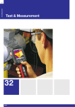
Specifications
Standard
Salt-damage proof/
Winterized type
Note:
Products of the salt-damage proof/winterized specifications are produced only on an order basis.
AISIN SEIKI CO., LTD.
AISIN
Aisin gas heat pump
PREFACE
Safety Precautions
The safety precautions to be strictly observed in order to avoid possible damage to persons engaged in
the maintenance of the multi-unit P224/P280/P355 and to other persons, are described using the
following methods:
In this manual, hazards and damage likely to result from improper maintenance operations are
WARNING” and “
CAUTION”. Be absolutely certain to
represented using the markings “
observe these warnings and precautions.
[Meaning of Markings]
WARNING This marking is followed by a description of the situation in which failure to
observe this warning could result in personal death or serious injury.
CAUTION
This marking is followed by a description of the situation in which failure to
observe this precaution could lead to personal injury and/or product damage.
)Before starting maintenance operations:
WARNING
1. Turn off the leakage current circuit breaker located inside the control box of the
outdoor unit.
– Failure to observe this warning may result in electrical shock.
2. Close the fuel gas cock.
– Fuel gas leakage may induce gas poisoning and/or gas explosion.
) During maintenance:
WARNING
1.
Wear the clothes that fit the nature of the work.
2.
Beware so as not to touch hot sections or rotating bodies.
– Touching could result in burns or injury.
3. Do not apply a valve cleaner to hot sections when cleaning valves.
– Failure to observe this warning may result in fire.
) About brazing operations:
CAUTION
For brazing, conduct nitrogen gas blowoff using the method specified in the relevant
service manual.
– Failure to observe this precaution could lead to pipeline clogging due to the occurrence of
oxide scales.
–1–
CONTENTS
Page
1.
SPECIFICATIONS ............................................................................................................. 1-1
1.1 Product External Views ...........................................................................................................................1-2
1.2 Product Specification ...............................................................................................................................1-3
1.2.1 Model Number and Product Name.......................................................................................1-3
1.2.2 Combination of Indoor Unit and Outdoor Unit....................................................................1-4
1.2.3 Structure Drawing ................................................................................................................1-7
1.2.4 Outdoor Unit Specifications .................................................................................................1-8
1.3 Outside Drawing of Outdoor Unit .........................................................................................................1-14
1.4 Outdoor Unit Internal Structure............................................................................................................1-16
1.5 Various Characteristics..........................................................................................................................1-18
1.5.1 Cooling and Heating Capabilities and Gas Consumption for Each Indoor Unit
Connection Capacities........................................................................................................1-18
1.5.2 Allowable Cooling and Heating Temperature Ranges .......................................................1-21
1.5.3 Changes According to Piping Length.................................................................................1-22
1.5.4 Fuel Comsunption ..............................................................................................................1-23
1.5.5 Outdoor Unit Operating Sound Characteristics.................................................................1-26
1.6 System Flow Chart .................................................................................................................................1-29
1.6.1 Refrigerant Circulation Diagrams and Description...........................................................1-29
1.6.2 Coolant/Fuel/Air Circulation Diagrams and Description..................................................1-31
2.
CONTROL ........................................................................................................................... 2-1
2.1 System Control Function List..................................................................................................................2-3
2.2 Remote Control Unit Functions ..............................................................................................................2-7
2.3 DIP Switches for Function Selection ......................................................................................................2-8
2.4 System Input/Output Specifications ......................................................................................................2-11
2.4.1 Indoor Unit Input/Output Specifications ............................................................................2-11
2.4.2 Outdoor Unit Input/Output Specifications..........................................................................2-13
2.5 Protection Units......................................................................................................................................2-15
2.5.1 Protection Units and Sensor Functions..............................................................................2-15
2.5.2 Sensor Mounting Positions.................................................................................................2-18
2.6 Outdoor Unit Electrical Wiring Diagrams ............................................................................................2-20
2.6.1 Outdoor Unit Electrical Wiring Diagram ..........................................................................2-20
2.6.2 Indoor Unit Wiring Diagram..............................................................................................2-23
3.
TROUBLE DIAGNOSIS AND REPAIR............................................................................ 3-1
3.1 Circuit Base Board Maintenance Functions ..........................................................................................3-2
3.2 Trouble Items and Diagnosis .................................................................................................................3-19
3.2.1 Error Codes, Contents, and Major Likely Causes..............................................................3-19
–2–
AISIN
Aisin gas heat pump
3.3 Diagnostic Items.....................................................................................................................................3-27
3.4 Trouble Diagnosis and Check ...............................................................................................................3-30
3.4.1 If the System Does Not Operate..........................................................................................3-30
3.4.2 If the Starter Does Not Operate..........................................................................................3-32
3.4.3 If the Engine Does Not Start...............................................................................................3-34
3.4.4 If the Engine Stalls .............................................................................................................3-39
3.4.5 Coolant Temperature Alarms .............................................................................................3-41
3.4.6 Oil Pressure Alarms ...........................................................................................................3-44
3.4.7 Engine Speed Too High Alarm ...........................................................................................3-45
3.4.8 High-Pressure Alarms During Cooling..............................................................................3-46
3.4.9 High-Pressure Alarms During Heating..............................................................................3-49
3.4.10 Refrigerant Low-Pressure Alarms......................................................................................3-51
3.4.11 Refrigerant Discharge Temperature Alarms ......................................................................3-53
3.4.12 Communications Trouble and Indoor Unit Circuit Trouble...............................................3-55
3.4.13 If Sufficient Cooling Cannot Be Obtained ..........................................................................3-57
3.4.14 If Sufficient Heating Cannot Be Obtained ..........................................................................3-59
4.
MAINTENANCE OF MAJOR FUNCTIONAL COMPONENTS.................................... 4-1
4.1 Engine Body Replacement.......................................................................................................................4-2
4.2 Cylinder Head Replacement ....................................................................................................................4-4
4.3 Compressor Replacement.........................................................................................................................4-7
5.
PERIODIC MAINTENANCE........................................................................................... 5-1
5.1 Periodic Maintenance Items and Periods................................................................................................5-2
5.2 Periodic Maintenance Procedures...........................................................................................................5-3
5.2.1 Changing Engine Oils ..........................................................................................................5-3
5.2.2 Replacing the Oil Filter........................................................................................................5-3
5.2.3 Replacing an Ignition Plug...................................................................................................5-3
5.2.4 Replacing the Air Element....................................................................................................5-4
5.2.5 Replacing the Compressor Belt ............................................................................................5-4
5.2.6 Adjusting the Valve Clearances............................................................................................5-5
5.2.7 Adding Coolant and Coolant Reinforcement........................................................................5-5
5.2.8 Checking the Coolant Hosing...............................................................................................5-5
5.2.9 Checking the Compressor.....................................................................................................5-6
5.2.10 Checking the Operational Sounds ........................................................................................5-6
5.2.11 Prevention of Valve Damage................................................................................................5-6
5.2.12 Replacing the Fuel Gas Hose ...............................................................................................5-6
–3–
6.
MAINTENANCE DATA STANDARDS........................................................................... 6-1
6.1 Engine-Related Components ...................................................................................................................6-2
6.2 Refrigerant-Related Components ............................................................................................................6-4
6.3 Electrical Equipment ...............................................................................................................................6-5
6.4 Coolant-Related Components ................................................................................................................6-10
6.5 Thermister Characteristics.....................................................................................................................6-11
–4–
AISIN
Aisin gas heat pump
3
SPECIFICATIONS
Chapter 1
SPECIFICATIONS
1.1
1.2
Product External Views
Product Specification
1.2.1 Model Number and Product Name
1.2.2 Combination of Indoor Unit and Outdoor Unit
1.2.3 Structure Drawing
1.2.4 Outdoor Unit Specifications
1.3
1.4
1.5
Outside Drawing of Outdoor Unit
Outdoor Unit Internal Structure
Various Characteristics
1.5.1 Cooling and Heating Capabilities and Gas Consumption for Each
Indoor Unit Connection Capacities
1.5.2 Allowable Cooling and Heating Temperature Ranges
1.5.3 Changes According to Piping Length
1.5.4 Fuel Consumptions
1.5.5 Outdoor Unit Operating Sound Characteristics
1.6
System Flow Chart
1.6.1 Refrigerant Circulation Diagrams and Description
1.6.2 Coolant/Fuel/Air Circulation Diagrams and Description
1-1
1
SPECIFICATIONS
1.1
Product External Views
4-/3-/2-way cassette type
4-/3-/2-way compact cassette type
2-way cassette type
FTKTPOOOM5
TKTCPOOOM5
TKTWPOOOM5
1-way cassette type
Built-in cassette type
Ceiling-embedded high
static-pressure duct type
TKTSPOOOM5
TKRPOOOM5
TKUPOOOM5
Ceiling-embedded medium
static-pressure duct type
Wall-mounted type
Floor-standing lowboy exposed
type
TKUMPOOOM5
TKKPOOOM5
TKFLPOOOM5
Floor-standing lowboy
concealed type
Ceiling-suspended type
Floor-standing type
TKFUPOOOM5
TKEPOOOM5
TKFPOOOM5
Outdoor unit
TGMP224/280/355** (Note 1)
Notes:
1. The double-asterisk symbol (**) denotes a serial code number
and differ according to the type of gas used.
2. The triple circle mark (ooo) in model numbers denote a
capacity.
3. Other than above, outside-air processing unit with a direct
expansion coil unit, air feed processing unit, ceiling-suspended
oil-resisting type, floor-standing plenum type, and
floor-standing duct type are available.
1-2
AISIN
Aisin gas heat pump
1.2
Product Specification
1.2.1
Model Number and Product Name
(1) Product name
Gas heat pump air conditioner outdoor unit
(2) Model number
New Refrigerant Building-Use Multi-Unit Model P224
New Refrigerant Building-Use Multi-Unit Model P280
New Refrigerant Building-Use Multi-Unit Model P355
TGMP224∗∗∗
TGMP280∗∗∗
TGMP355∗∗∗
[Description of outdoor unit model number]
Example: LPG specification(salt-damage proof type); TGMP280B2NE
T
G
Outdoor unit
M
P
2
Type
8
0
Capacity (kW)
S: Single
M: Building-use multi-type
N: Store-use multi-type
Refrigerant
P:
R407C
Capacity
224: 22.4 kW
280: 28.0 kW
355: 35.5 kW
B
1
Model change
additional No.
(in alphabetical
order)
N
E
Minor change
additional No.
(in numerical
order)
Gas type
N: 13A, 12A
P: Propane gas type A
C: Low-calorie gas type A
Special
specification
E: Salt-damage
proof type
H: Winterized type
* Blank for standard
specifications
[Description of serial number]
0
0
1
0
0
1
0
1
4
0
Assign a serial number beginning
with “00100101”.
[Description of indoor unit model number]
T
K
Indoor unit
T
W
Type
T: 4-way cassette type
TC: 4-way compact
cassette type
TW: 2-way cassette type
TS: 1-way cassette type
R: Built-in cassette
type
U: High static-pressure
duct type
UM: Medium staticpressure duct type
E: Ceiling-suspended
type
K: Wall-mounted type
FL: Floor-standing
lowboy (exposed)
P
1
M
Capacity (kW)
FU: Floor-standing lowboy
(concealed)
SA: Outside-air processing
unit with a direct
expansion coil unit
US: Air feed processing
unit
ES: Ceiling-suspended oilresisting type
FP: Floor-standing plenum
type
FD: Floor-standing duct
type
F: Floor-standing type
RC: Remote control unit
*
(blank): Closer to left
1-3
5
Type of outdoor Serial No. for
unit connected design
Example:
280: 28 kW
140: 14 kW
90: 9 kW
71: 7.1 kW
45: 4.5 kW
* Omitted for remote
control units
S: Js series
M: Jm series
* Design-serial No. for
remote control units
1
SPECIFICATIONS
1.2.2
Combination of Indoor Unit and Outdoor Unit
(1) Model P224 outdoor unit (TGMP224∗∗∗)
P22
P28
P36
P45
P56
P71
P80
P90
P112 P140
2.2
(kW)
2.8
(kW)
3.6
(kW)
4.5
(kW)
5.6
(kW)
7.1
(kW)
8.0
(kW)
9.0
(kW)
11.2
(kW)
14.0
(kW)
16.0
(kW)
4-/3-/2-way cassette type
TKT
{
{
{
{
{
{
{
{
{
{
4-/3-/2-way compact
cassette type
TKTC
{
{
{
{
{
{
{
{
{
{
{
{
{
{
{
{
{
{
{
{
{
{
{
{
{
{
{
{
{
{
{
{
{
{
{
{
{
{
{
{
{
{
{
{
{
{
{
{
{
Model No.
Type
2-way cassette type
TKTW
{
1-way cassette type
TKTS
Built-in cassette type
TKR
Ceiling-embedded high
static-pressure duct type
TKU
Ceiling-embedded medium
static-pressure duct type
TKUM
{
{
{
Ceiling-suspended type
TKE
Wall-mounted type
TKK
Floor-standing lowboy
(exposed)
TKFL
Floor-standing lowboy
(concealed)
TKFU
Outside-air processing unit
with a direct expansion coil
unit
TKSA
{
P160 P224
P280
22.4
(kW)
28.4
(kW)
{
{
{
{
{
{
{
{
{
{
{
{
{
{
{
{
Air feed processing unit
TKUS
{
Ceiling-suspended
oil-resisting type
TKES
Floor-standing plenum
type
TKFP
{
{
{
{
Floor-standing duct type
TKFD
Floor-standing type
TKF
{
Capacity available
Outdoor unit capacity ratio: Approx. 50 to 130%
(Total capacity of indoor units: P112 to P291)
Number of connectable
indoor units
{
1 to 12 units
Note:
The capabilities of indoor units slightly decrease during the simultaneous operation of these units in
excess of a 100% outdoor unit capacity ratio.
1-4
AISIN
Aisin gas heat pump
(2) Model P280 outdoor unit (TGMP280∗∗∗)
P22
P28
P36
P45
P56
P71
P80
P90
P112 P140 P160 P224 P280
2.2
(kW)
2.8
(kW)
3.6
(kW)
4.5
(kW)
5.6
(kW)
7.1
(kW)
8.0
(kW)
9.0
(kW)
11.2
(kW)
14.0
(kW)
16.0
(kW)
4-/3-/2-way cassette type
TKT
{
{
{
{
{
{
{
{
{
{
4-/3-/2-way compact
cassette type
TKTC
{
{
{
{
{
{
{
{
{
{
{
{
{
{
{
{
{
{
{
{
{
{
{
{
{
{
{
{
{
{
{
{
{
{
{
{
{
{
{
{
{
{
{
{
{
{
{
{
{
Model No.
Type
2-way cassette type
TKTW
{
1-way cassette type
TKTS
Built-in cassette type
TKR
{
Ceiling-embedded high
static-pressure duct type
TKU
Ceiling-embedded
medium static-pressure
duct type
TKUM
{
{
Ceiling-suspended type
TKE
Wall-mounted type
TKK
{
Floor-standing lowboy
(exposed)
TKFL
{
{
{
{
Floor-standing lowboy
(concealed)
TKFU
{
{
{
{
Outside-air processing
unit with a direct
expansion coil unit
TKSA
{
{
{
22.4
(kW)
28.4
(kW)
{
{
{
{
{
{
{
Air feed processing unit
TKUS
{
Ceiling-suspended
oil-resisting type
TKES
{
Floor-standing plenum
type
TKFP
{
{
{
Floor-standing duct type
TKFD
Floor-standing type
TKF
{
Capacity available
Outdoor unit capacity ratio: Approx. 50 to 130%
(Total capacity of indoor units: P140 to P364)
Number of connectable
indoor units
{
1 to 12 units
Note:
The capabilities of indoor units slightly decrease during the simultaneous operation of these units in
excess of a 100% outdoor unit capacity ratio.
1-5
1
SPECIFICATIONS
(3) Model P355 outdoor unit (TGMP355∗∗∗)
P22
P28
P36
P45
P56
P71
P80
P90
P112 P140 P160 P224 P280
2.2
(kW)
2.8
(kW)
3.6
(kW)
4.5
(kW)
5.6
(kW)
7.1
(kW)
8.0
(kW)
9.0
(kW)
11.2
(kW)
14.0
(kW)
16.0
(kW)
4-/3-/2-way cassette type
TKT
{
{
{
{
{
{
{
{
{
{
4-/3-/2-way compact
cassette type
TKTC
{
{
{
{
{
{
{
{
{
{
{
{
{
{
{
{
{
{
{
{
{
{
{
{
{
{
{
{
{
{
{
{
{
{
{
{
{
{
{
{
{
{
{
{
{
{
{
{
{
Model No.
Type
2-way cassette type
TKTW
{
1-way cassette type
TKTS
Built-in cassette type
TKR
{
Ceiling-embedded high
static-pressure duct type
TKU
Ceiling-embedded
medium static-pressure
duct type
TKUM
{
{
Ceiling-suspended type
TKE
Wall-mounted type
TKK
{
Floor-standing lowboy
(exposed)
TKFL
{
{
{
{
Floor-standing lowboy
(concealed)
TKFU
{
{
{
{
Outside-air processing unit
with a direct expansion
coil unit TKSA
{
{
{
22.4
(kW)
28.4
(kW)
{
{
{
{
{
{
{
Air feed processing unit
TKUS
{
Ceiling-suspended
oil-resisting type
TKES
{
Floor-standing plenum
type
TKFP
{
{
{
Floor-standing duct type
TKFD
Floor-standing type
TKF
{
Capacity available
Outdoor unit capacity ratio: Approx. 50 to 130%
(Total capacity of indoor units: P178 to P462)
Number of connectable
indoor units
{
1 to 12 units
Note:
The capabilities of indoor units slightly decrease during the simultaneous operation of these units in
excess of a 100% outdoor unit capacity ratio.
1-6
AISIN
Aisin gas heat pump
1.2.3 Structure drawing
Refrigerant pipe
Signal wire
Electrical wire
Power supply
Single phase 200V
Or three phase 200V
Indoor unit
Indoor unit
Overcurrent
breaker
Drain pipes
VP25
Drain pipes
VP25
Remote
controller
Outdoor unit
Indoor unit
Remote
controller
Remote
controller
Indoor unit
Note
Outdoor
unit
Class-three
Ground
Exhaust drain
pipes
Single
phase 200V
Three
phase
200V
Single phase
200V
○
×
Three phase
200V
×
○
Wiring power supply from outdoor unit (possible
to wire separately)
× wiring separately
Refrigerant gas pipe
TGMP224B
25 4
TGMP280B
28 58
TGMP355B
31.8
Fuel gas pipe R3/4
Refrigerant liquid pipe
φ12.7
Electrical wire
and signal wire
inlet
Condensation
drain
Drain pipes
VP25
Exhaust air drain hose
Connecting position for piping wiring (Rear
side of outdoor unit)
1-7
1
SPECIFICATIONS
1.2.4 Outdoor unit Specification
City gas 13A (12A) specifications
TGMP224B2N
Cooling rating
Scroll type×2
P224 Multi for building
Exclusion capacity
L/rev
0.0605X2
22.4
Revolution range
min-1
(cooling) 2280 to 3085
min-1
(heating) 2280 to 3895
kW
Heating rating
Outer
dimensions
Operating Sound
26.5
dB
Normal 53, Silent Mode 51
Refrigerator oil enclosure q’ty
Width
1398
Power transfer method
Poly V-belting
Depth
798
Type
R407C
Sealing amount
13
Outdoor unit heat exchanger
Slit fin
Exhaust gas heat exchanger
Multi-pipe heat exchanger
Engine radiator
Louver fin
3.6GY 8.0/0.9
DIC546 1/2
4
V
Single phase 200 /
Three phase 200
Starting current
A
20
Running current
(A)
Cooling
3.9/4.7, 2.3/2.7
Heating
4.0/4.7, 2.3/2.7
Air suction port
Front and rear side
Power
consumption
(kw)
Cooling
0.74/0.90
Air blowing port
Upper
Heating
0.76/0.92
Exhaust heat absorption
Heating refrigerant in double pipe
Cooling
95/96, 93/96
Heating
95/98, 95/98
Cooling
kW
Heating
18.6
17.5
Water-cooled vertical type,
4-cycle, 3-cylinder OHV
Type
L
0.952
Rated output
kW
7.5
Revolution
range
min-1
Lubrica
ting oil
Exhaust volume
Type
Capacity
(Cooling) 1200 to 1650
L
Type
Refrigeran
t piping
Liquid
pipe
mm
Gas pipe
Propeller fan ×2
210
Single-phase induction motor (8P)
180X2
φ12.7 flare connection
φ25.4 flange connection
Fuel gas pipe
R 3/4
Exhaust drain pipe
mm
φ15
(Heating) 1200 to 2050
35
Upper side
Aisin Coolant S
Sealing amount
L
14
Concentration
%
65
Freezing
temperature
°C
-35
Type
Pump
Type × Number of units
Rated air
3
m /min
amount
Type
Motor
Rated
W
output
Aisin GHP Oil L10000
Exhaust port position
Motor
output
Pipe dimensions
Power ratio(%)
Fan
Power source
Cons
umption
Fuel
L
Heat exchanger
Exterior color (DIC)
Electricity characteristics
530
Engine
NL10
1866
Mass
Engine coolant
Specified refrigerator oil
Height
Refrigerant
Capability
Type
Type × Number of units
Compressor
Model No.
(50/60HZ)
W
125 (Equivalent length)
Permissible pipe length
100 (Actual length)
Permissible difference in
elevation between
indoor/outdoor unit
m
50(Outdoor unit at top)
40(Outdoor unit at bottom)
Permissible difference in
elevation between indoor units
15
number
1 to 12
Magnet type spiral pump
Connectable indoor
units
capacity
P22 to P224
105/150
Legal freezing capacity
RT
2.3
Notes:
1. The cooling/heating capability and electrical characteristics data shown in the above table was measured
under the conditions of JIS B 8627.
2. The operating sound level shown in the above table was measured in an anechoic room, subject to the
relevant provisions of JIS. Under actual conditions, the operating sound level shown above is usually exceeded
since it is affected by ambient noise and the echoes of the installation room.
1-8
AISIN
Aisin gas heat pump
Propane gas specifications
(50/60HZ)
TGMP224B2P
Cooling rating
Scroll type×2
P224 Multi for building
Exclusion capacity
L/rev
0.0605X2
22.4
Revolution range
min-1
(cooling) 2280 to 3040
min-1
(heating) 2280 to 3895
kW
Heating rating
Outer
dimensions
Operating Sound
26.5
dB
Normal 53, Silent Mode 51
Refrigerator oil enclosure q’ty
Width
1398
Power transfer method
Poly V-belting
Depth
798
Type
R407C
Sealing amount
13
Outdoor unit heat exchanger
Slit fin
Exhaust gas heat exchanger
Multi-pipe heat exchanger
Engine radiator
Louver fin
L
4
V
Single phase 200 /
Three phase 200
Starting current
A
20
Running current
(A)
Cooling
3.9/4.7, 2.3/2.7
Heating
4.0/4.7, 2.3/2.7
Air suction port
Front and rear side
Power
consumption
(kw)
Cooling
0.74/0.90
Air blowing port
Upper
Heating
0.76/0.92
Exhaust heat absorption
Heating refrigerant in double pipe
Cooling
95/96, 93/96
Heating
95/98, 95/98
Fuel
Cons
umption
Power ratio(%)
Cooling
kW
Heating
18.6
17.5
L
0.952
Rated output
kW
6.0
Revolution
range
min-1
Lubrica
ting oil
Exhaust volume
Type
Capacity
(Cooling) 1200 to 1600
(Heating) 1200 to 2050
Type × Number of units
Rated air
3
m /min
amount
Type
Motor
Rated
W
output
Liquid
Refrigeran pipe
mm
t piping
Gas pipe
Propeller fan ×2
Fuel gas pipe
R 3/4
Exhaust drain pipe
mm
180
Single-phase induction motor (8P)
180X2
φ12.7 flare connection
φ25.4 flange connection
φ15
Aisin GHP Oil L10000
L
35
Exhaust port position
Upper side
Type
Aisin Coolant S
Sealing amount
L
14
Concentration
%
65
Freezing temperature
°C
-35
Type
Motor
output
Pipe dimensions
Water-cooled vertical type,
4-cycle, 3-cylinder OHV
Type
Pump
Fan
Power source
Heat exchanger
Exterior color (DIC)
3.6GY 8.0/0.9
DIC546 1/2
Electricity characteristics
530
Engine
NL10
1866
Mass
Engine coolant
Specified refrigerator oil
Height
Refrigerant
Capability
Type
Type × Number of units
Compressor
Model No.
W
125 (Equivalent length)
Permissible pipe length
100 (Actual length)
Permissible difference in
elevation between
indoor/outdoor unit
m
50(Outdoor unit at top)
40(Outdoor unit at bottom)
Permissible difference in
elevation between indoor units
15
number
1 to 12
Magnet type spiral pump
Connectable indoor
units
capacity
P22 to P224
105/150
Legal freezing capacity
RT
2.3
Notes:
1. The cooling/heating capability and electrical characteristics data shown in the above table was measured
under the conditions of JIS B 8627.
2. The operating sound level shown in the above table was measured in an anechoic room, subject
to the relevant provisions of JIS. Under actual conditions, the operating sound level shown above is
usually exceeded since it is affected by ambient noise and the echoes of the installation room.
1-9
1
SPECIFICATIONS
City gas 13A (12A) specifications
Model No.
TGMP280B2N
P280 Multi for building
Heating rating
Outer
dimensions
Operating Sound
kW
dB
28.0
33.5
Normal 57, Silent Mode 55
L/rev
0.0605X2
Revolution range
min-1
(cooling) 2280 to 4085
min-1
(heating) 2280 to 4845
Specified refrigerator oil
NL10
Width
1398
Power transfer method
Poly V-belting
Depth
798
Type
R407C
Sealing amount
13
Outdoor unit heat exchanger
Slit fin
Exhaust gas heat exchanger
Multi-pipe heat exchanger
Engine radiator
Louver fin
3.6GY 8.0/0.9
DIC546 1/2
L
4
V
Single phase 200 /
Three phase 200
Starting current
A
20
Running current
(A)
Cooling
5.0/5.9, 2.9/3.4
Heating
5.3/6.1, 3.1/3.5
Air suction port
Front and rear side
Powerconsumption
(kw)
Cooling
0.96/1.15
Air blowing port
Upper
Heating
1.01/1.19
Exhaust heat absorption
Heating refrigerant in double pipe
Cooling
96/97, 96/98
Type × Number of units
Propeller fan ×2
95/98, 94/98
Rated air
amount
m /min
210
Type
Single-phase induction motor
(8P)
Power ratio(%)
Consu
mption
Heating
Cooling
24.5
Motor
kW
Heating
22.4
L
0.952
Rated output
kW
7.5
Revolution
range
min-1
Lubricat
ing oil
Exhaust volume
Type
Capacity
(Cooling) 1200 to 2150
(Heating) 1200 to 2550
Refrigeran
t piping
3
Rated
output
W
Liquid
pipe
mm
Gas pipe
220X2
φ12.7 flare connection
φ28.58 flange connection
Fuel gas pipe
R 3/4
Exhaust drain pipe
mm
φ15
Aisin GHP Oil L10000
L
Exhaust port position
Type
35
Upper side
Aisin Coolant S
Sealing amount
L
15.5
Concentration
%
65
Freezing temperature
°C
-35
Type
Motor
output
Pipe dimensions
Water-cooled vertical type,
4-cycle, 3-cylinder OHV
Type
Pump
Fan
Power source
Heat exchanger
Exterior color (DIC)
Electricity characteristics
Exclusion capacity
Refrigerator oil enclosure q’ty
560
Fuel
Scroll type×2
2118
Mass
Engine
Type × Number of units
Height
Refrig
erant
Capa
bility
Cooling rating
Compressor
Type
Engine coolant
(50/60HZ)
W
125 (Equivalent length)
Permissible pipe length
100 (Actual length)
Permissible difference in
elevation between
indoor/outdoor unit
m
50(Outdoor unit at top)
40(Outdoor unit at bottom)
Permissible difference in
elevation between indoor units
15
number
1 to 12
Magnet type spiral pump
Connectable indoor
units
capacity
P22 to P280
105/150
Legal freezing capacity
RT
3.0
Notes:
1. The cooling/heating capability and electrical characteristics data shown in the above table was measured
under the conditions of JIS B 862.
2. The operating sound level shown in the above table was measured in an anechoic room, subject to the
relevant provisions of JIS. Under actual conditions, the operating sound level shown above is usually
exceeded since it is affected by ambient noise and the echoes of the installation room.
1-10
AISIN
Aisin gas heat pump
Propane gas specifications
(50/60HZ)
TGMP280B2P
Type
Scroll type×2
P280 Multi for building
Exclusion capacity
L/rev
0.0605X2
28.0
Revolution range
min-1
(cooling) 2280 to 4085
min-1
(heating) 2280 to 4845
kW
Heating rating
Outer
dimensions
Operating Sound
33.5
dB
Normal 57, Silent Mode 55
Refrigerator oil enclosure q’ty
Width
1398
Power transfer method
Poly V-belting
Depth
798
Type
R407C
Sealing amount
13
Outdoor unit heat exchanger
Slit fin
Exhaust gas heat exchanger
Multi-pipe heat exchanger
Engine radiator
Louver fin
Exterior color (DIC)
3.6GY 8.0/0.9
DIC546 1/2
20
Running current
(A)
5.0/5.9, 2.9/3.4
Heating
5.3/6.1, 3.1/3.5
Air suction port
Front and rear side
Cooling
0.96/1.15
Air blowing port
Upper
Heating
1.01/1.19
Exhaust heat absorption
Heating refrigerant in double
pipe
Cooling
96/97, 96/98
Type × Number of units
Propeller fan ×2
Heating
95/98, 94/98
Rated air
amount
m /min
210
Type
Single-phase induction motor
(8P)
Power
consumption
(kw)
Power ratio(%)
V
Cooling
Single phase 200 /
Three phase 200
24.5
kW
Heating
Motor
22.4
L
0.952
Rated output
kW
7.5
Revolution
range
min-1
Lubrica
ting oil
Exhaust volume
Type
Capacity
(Cooling) 1200 to 2150
(Heating) 1200 to 2550
Refrigeran
t piping
3
Rated
output
Liquid
pipe
W
mm
Gas pipe
220X2
φ12.7 flare connection
φ28.58 flange connection
Fuel gas pipe
R 3/4
Exhaust drain pipe
mm
φ15
Aisin GHP Oil L10000
L
Exhaust port position
Type
35
Upper side
Aisin Coolant S
Sealing amount
L
15.5
Concentration
%
65
Freezing temperature
°C
-35
Type
Motoroutput
Pipe dimensions
Water-cooled vertical type,
4-cycle, 3-cylinder OHV
Type
Pump
Fan
A
Cooling
Consum
ption
Electricity characteristics
4
Starting current
Power source
Fuel
L
Heat exchanger
560
Engine
NL10
2118
Mass
Engine coolant
Specified refrigerator oil
Height
Refrig
erant
Capability
Cooling rating
Type × Number of units
Compressor
Model No.
W
125 (Equivalent length)
Permissible pipe length
100 (Actual length)
Permissible difference in
elevation between
indoor/outdoor unit
Permissible difference in
elevation between indoor
units
m
50(Outdoor unit at top)
40(Outdoor unit at bottom)
15
number
1 to 12
Magnet type spiral pump
Connectable indoor
units
capacity
P22 to P280
105/150
Legal freezing capacity
RT
3.0
Notes:
1. The cooling/heating capability and electrical characteristics data shown in the above table was measured
under the conditions of JIS B 8627.
2. The operating sound level shown in the above table was measured in an anechoic room, subject to the
relevant provisions of JIS. Under actual conditions, the operating sound level shown above is usually exceeded
since it is affected by ambient noise and the echoes of the installation room.
1-11
1
SPECIFICATIONS
13A (12A) specifications
Cooling rating
35.5 kW
Heating rating
42.5 kW
58 dB (56 dB in silent mode)
Height
2118 mm
Width
1398 mm
Depth
798 mm
Mass
560 kg
Exterior color [Munsell]
3.6GY8.0/9.0 or equivalent
DIC546 1/2
Revolution range
Specified refrigerator oil
Refrigerator oil enclosure q’ty
Power transfer method
Refrigerant
Operating sound
Heat
exchanger
Capability
Exclusion capacity
New Refrigerant Model P355
Building-Use Multi-Unit
Type
Outer
dimensions
Type × Number of units
TGMP355B2N
Compressor
Model No.
Type
–1
2280 to 4655 min (Cooling)
–1
2280 to 4845 min (Heating)
NL10
4L
Poly V-belting
Enclosure q’ty
13 kg
Outdoor unit heat exchanger
Slit fin
Exhaust gas heat exchanger
Multi-pipe heat exchanger
Engine radiator
Louver fin
Front and rear
Air blowing port
Top
Running current
5.0/5.9, 2.9/3.4 A (Cooling)
5.3/6.1, 3.1/3.5 A (Heating)
Electrical characteristics
Air suction port
20 A
0.961.15 kW (Cooling)
1.10/1.19 kW (Heating)
Type × Number of units
Power ratio
96/97, 96/98% (Cooling)
95/98, 94/98% (Heating)
Rated air amount
Fuel
200 V single-phase
Starting current
Power consumption
Consumption
29.9 kW (Cooling rating)
29.6 kW (Heating rating)
Fan
Exhaust heat collection method
Motor
952 cm
Rated output
9.5 kW
–1
Revolution range
Lubricating oil type
1200 to 2450 min
(Cooling)
–1
1200 to 2550 min
(Heating)
Aisin Gas Engine Oil
(L10000)
Pipe dimensions
3
Exhaust volume
Type
Rated output
Water-cooled vertical type,
4-cycle, 3-cylinder OHV
Type
Engine
3
R407C
Power source
Refrigerant
piping
Refrigerant heating
Propeller fan × 2
3
210 m /min
Single-phase induction
motor (6P)
0.22 kW
Liquid pipe
φ12.7 mm
Flare-connected
Gas pipe
φ31.8 mm
Flange-mounted
Fuel gas pipe
Exhaust drain pipe
Permissible pipe length
R3/4
φ15 mm
125 m (Equivalent length)
100 m (Actual length)
50 m (Outdoor unit upper)
Lubricating oil enclosure
q’ty
35 L
Permissible difference in elevation
between indoor/outdoor units
Exhaust port position
Top
Permissible difference in elevation
between indoor units
15 m
Number of indoor units which can
be combined
1 to 12 units
(Capacity: P22 to P280)
Type
Aisin Coolant S
Enclosure q’ty
Concentration
Freezing temperature
Pump
Coolant
Scroll type × 2
60.5 cm /rev × 2
Type
Motor rated output
15.5 L
50%
Legal freezing capacity
40 m (Outdoor unit lower)
3.4 RT
–35°C
Magnet type spiral pump
(50/60 Hz)
0.105/0.150 kW
Notes:
1. The cooling/heating capability and electrical characteristics data shown in the above table was measured
under the conditions of JIS B 8627.
2. The operating sound level shown in the above table was measured in an anechoic room, subject to the
relevant provisions of JIS. Under actual conditions, the operating sound level shown above is usually exceeded
since it is affected by ambient noise and the echoes of the installation room.
1-12
AISIN
Aisin gas heat pump
Class-A propane gas specifications
Cooling rating
35.5 kW
Heating rating
42.5 kW
2118 mm
Width
1398 mm
Depth
798 mm
Mass
560 kg
Exterior color [Munsell]
Revolution range
Specified refrigerator oil
Power transfer method
58 dB (56 dB in silent mode)
Height
Refrigerant
Operating sound
3.6GY8.0/9.0 or equivalent
DIC546 1/2
Type
Enclosure q’ty
2280 to 4655 min (Cooling)
–1
2280 to 4845 min
(Heating)
NL10
4L
Poly V-belting
13 kg
Outdoor unit heat exchanger
Slit fin
Exhaust gas heat exchanger
Multi-pipe heat exchanger
Engine radiator
Louver fin
Front and rear
Starting current
20 A
Air blowing port
Top
Running current
5.0/5.9, 2.9/3.4 A (Cooling)
5.3/6.1, 3.1/3.5 A (Heating)
Electrical characteristics
Air suction port
0.95/1.15 kW (Cooling)
1.10/1.19 kW (Heating)
Type × Number of units
Power ratio
96/97, 96/98% (Cooling)
95/98, 94/98% (Heating)
Rated air amount
Fuel
200 V single-phase
Power consumption
Consumption
29.9 kW (Cooling rating)
29.6 kW (Heating rating)
Exhaust volume
Rated output
952 cm
3
9.5 kW
–1
Revolution range
Lubricating oil type
Lubricating oil enclosure
q’ty
Exhaust port position
Type
Aisin Gas Engine Oil
(L10000)
Concentration
Freezing temperature
Type
Motor rated output
Fan
Motor
Type
Rated output
Refrigerant
piping
Refrigerant heating
Propeller fan × 2
3
210 m /min
Single-phase induction
motor (6P)
0.22 kW
Liquid pipe
φ12.7 mm
Flare-connected
Gas pipe
φ31.8 mm
Flange-mounted
Fuel gas pipe
Exhaust drain pipe
Permissible pipe length
R3/4
φ15 mm
125 m (Equivalent length)
100 m (Actual length)
50 m (Outdoor unit upper)
35 L
Permissible difference in elevation
between indoor/outdoor units
Top
Permissible difference in elevation
between indoor units
15 m
Number of indoor units which can
be combined
1 to 12 units
(Capacity: P22 to P280)
Aisin Coolant S
Enclosure q’ty
Pump
1200 to 2450 min
(Cooling)
–1
1200 to 2550 min
(Heating)
Exhaust heat collection method
Pipe dimensions
Water-cooled vertical type,
4-cycle, 3-cylinder OHV
Type
Engine
3
R407C
Power source
Coolant
Scroll type × 2
60.5 cm /rev × 2
–1
Refrigerator oil enclosure q’ty
Heat
exchanger
Capability
Exclusion capacity
New Refrigerant Model P355
Building-Use Multi-Unit
Type
Outer
dimensions
Type × Number of units
TGMP355B2P
Compressor
Model No.
15.5 L
50%
Legal freezing capacity
40 m (Outdoor unit lower)
3.4 RT
–35°C
Magnet type spiral pump
0.105/0.150 kW
(50/60 Hz)
Notes:
1. The cooling/heating capability and electrical characteristics data shown in the above table was measured
under the conditions of JIS B 8627.
2. The operating sound level shown in the above table was measured in an anechoic room, subject to the
relevant provisions of JIS. Under actual conditions, the operating sound level shown above is usually exceeded
since it is affected by ambient noise and the echoes of the installation room.
1-13
Hour meter
4-φ20
Anchor hole
4-φ20
Exhaust port
(5)
(4)
φ30.0
1-14
(5) Power
cable inlet
(2) Refrigerant
liquid pipe
connecting port
1 position
Exhaust drain hose with heating
Power cable outlet
R3/4
φ15.0
(3)
For installing one unit
Installation space
For installing more than one unit
Note: Provide a space of at least 800 mm if a snow
hood is to be mounted.
(3) Fuel pipe connecting port
connecting port
(1) Refrigerant gas pipe
Condensate drain port
Base
Min. 2000
When installing four units or more, provide a maintenance
space for every three units.
Note: Provide a space of at least 800 mm if a snow
hood is to be mounted.
(4) Exhaust drain hose
φ28.58
φ12.7
TGMP280
Exhaust drain hose
Refrigerant liquid pipe
(2)
φ25.4
TGMP224
Fuel gas pipe
Refrigerant gas pipe
Description
(1)
Symbol
(Note)
(Note)
1.3
(Note)
1
SPECIFICATIONS
Outside Drawing of Outdoor Unit
(1) TGMP224B
Hour meter
4-φ20
4-φ20
Anchor hole
Description
(5)
(4)
(5)
(3)
(4)
1-15
(5) Power
cable inlet
(2) Refrigerant
liquid pipe
connecting port
Power cable outlet
1 position
position
ƒ1 30.0
Ó
Exhaust
drain
hose
with heating
Exhaust
drain
hose
Power cable outlet
Exhaust drain hose with heating
R3/4
φ15.0
Ó 15.0
ƒ
φ30.0
Exhaust
drain
Fuel
gashose
pipe
Symbol
Refrigerant gas Description
pipe
Ó 28.58
TGMP280 ƒ
(1)(1)
φ31.8
Refrigerant gas pipe
Ó 31.8
ƒ
TGMP335
Refrigerant liquid pipe
(2)
φ12.7
Ó 12.7
ƒ
(2)
Refrigerant
liquid
pipe
(3)
R3/4
Fuel gas pipe
Sym bol
For installing one unit
Installation space
(Note)
For installing more than one unit
Note: Provide a space of at least 800 mm if a snow
hood is to be mounted.
(Note)
(1) Refrigerant gas pipe
connecting port
Condensate drain port
(4) Exhaust drain hose
(3) Fuel pipe connecting port
Min. 2000
Base
When installing four units or more, provide a maintenance
space for every three units.
Note: Provide a space of at least 800 mm if a snow
hood is to be mounted.
(Note)
Exhaust port
Aisin gas heat pump
AISIN
(2) TGMP280/355B
1
SPECIFICATIONS
1.5
Outdoor Unit Internal Structure
(2)
(1)
(3)
(8)
(9)
(4)
(10)
(20)
(11)
(12)
(13)
(21)
(14)
(5)
(22)
(15)
(16)
(23)
(6)
(7)
(17)
(18)
(19)
(1)
(2)
(3)
(4)
(5)
(6)
(7)
(8)
(9)
(10)
Exhaust port
Radiator cap
Reserve tank filling port
Intake air silencer
Air cleaner
Oil filter
Engine oil pressure switch
Outdoor unit heat exchanger
Radiator
Gas mixer
(11)
(12)
(13)
(14)
(15)
(16)
(17)
(18)
(19)
(20)
Coolant temperature sensor
Engine
Discharge temperature sensor (L)
Compressor (L)
Compressor belt (L)
Oil subtank
Engine anti-vibration rubber (L)
Oil pan
Engine anti-vibration rubber (R)
Electric three-way valve
1-16
(26)
(21)
(22)
(23)
(24)
(25)
(26)
(24)
(25)
Control circuit board
Exhaust heat exchanger
Power supply unit
Discharge temperature sensor (R)
Compressor (R)
Compressor belt (R)
AISIN
Aisin gas heat pump
(1)
(11)
(2)
(12)
(13)
(3)
(4)
(5)
(6)
(7)
(8)
(9)
(10)
(15)
(14)
(35)
(16)
(17)
(18)
(23)
(24)
(25)
(26)
(27)
(19)
(20)
(28)
(29)
(21)
(22)
(32)
(30)
(31)
(33) (34)
(1) Discharge flexible tube (for
capacity control)
(2) Low-pressure switch
(11) Discharge flexible tube
(20) Accumulator
(12) Intake flexible tube
(21) Coolant pump
(3) Accumulator inlet temperture
sensor
(4) Gas pipe temperature sensor
(13) Intake temperature
sensor
(14) Ignition coil
(22) Double-pipe heat
exchanger
(23) High-pressure sensor
(5) Capacity regulating valve
(15) Reserve tank
(24) High-pressure switch
(6) Liquid flow regulating valve
(16) Outdoor fan
(25) High-pressure service
port
(26) Oil-operated solenoid
valve
(27) Hot gas bypass valve
(28) Terminal block
(29) Filter drier
(7) Heat exchanger liquid
(17)
temperature sensor
(8) Low-pressure service port
(18)
(9) Four-way changeover valve
(19)
(10) Engine room temperature sensor
(mounted on the top plate)
Outside air temperature
sensor
Fan motor
Filter drier
1-17
(37)
(36)
(30) Refrigerant liquid pipe
connecting port
(31) Refrigerant gas pipe
connecting port
(32) Drain filter
(33) Engine anti-vibration
rubber (rear)
(34) Gas regulator (with gas
electromagnetic valve)
(35) Outdoor unit heat
exchanger
(36) Exhaust fan
(37) Fuel gas hose
1
SPECIFICATIONS
1.5
1.5.1
Various Characteristics
Cooling and Heating Capabilities and Gas Consumption for Each Indoor Unit Connection
Capacities
(1) TGMP224B2
Indoor Unit Connection Capacity
Total Capabilities [kW]
Gas Consumption [kW]
New JIS
Marking
[kW]
Cooling
Heating
Cooling
Heating
291
29.1
23.8
27.2
19.3
16.4
280
28.0
23.7
27.1
19.3
16.6
270
27.0
23.6
27.0
19.1
16.8
260
26.0
23.3
26.9
19.0
16.9
250
25.0
23.1
26.8
18.9
17.0
240
24.0
22.7
26.7
18.8
17.2
230
23.0
22.5
26.6
18.7
17.4
224
22.4
22.4
26.5
18.6
17.5
220
22.0
22.0
26.0
18.3
17.2
210
21.0
21.0
24.9
17.5
16.6
200
20.0
20.0
23.7
16.7
15.9
190
19.0
19.0
22.5
16.0
15.3
180
18.0
18.0
21.3
15.4
14.6
170
17.0
17.0
20.2
15.1
14.0
160
16.0
16.0
19.0
14.9
13.6
150
15.0
15.0
18.0
14.6
13.4
140
14.0
14.0
17.0
14.2
13.3
130
13.0
13.0
15.6
16.5
13.1
120
12.0
12.0
14.3
15.2
12.9
112
11.2
11.2
13.2
14.1
13.8
1-18
AISIN
Aisin gas heat pump
(2) TGMP280B2
Indoor Unit Connection Capacity
Total Capabilities [kW]
Gas Consumption [kW]
New JIS
Marking
[kW]
Cooling
Heating
Cooling
Heating
364
36.4
29.7
34.6
25.4
21.0
360
36.0
29.6
34.5
25.4
21.1
350
35.0
29.4
34.3
25.3
21.3
340
34.0
29.2
34.2
25.2
21.4
330
33.0
29.0
34.1
25.1
21.6
320
32.0
28.8
34.0
25.0
21.8
310
31.0
28.6
33.9
24.8
21.9
300
30.0
28.4
33.7
24.7
22.0
290
29.0
28.2
33.6
24.6
22.2
280
28.0
28.0
33.5
24.5
22.4
270
27.0
27.0
32.3
23.7
21.6
260
26.0
26.0
31.0
22.9
20.7
250
25.0
25.0
29.8
22.1
19.8
240
24.0
24.0
28.5
21.3
19.0
230
23.0
23.0
27.3
20.5
18.1
224
22.4
22.4
26.5
19.2
17.1
220
22.0
22.0
26.0
18.4
16.5
210
21.0
21.0
24.9
17.6
15.8
200
20.0
20.0
23.7
16.8
15.2
190
19.0
19.0
22.5
16.2
14.5
180
18.0
18.0
21.3
15.9
13.9
170
17.0
17.0
20.2
15.6
13.5
160
16.0
16.0
19.0
15.3
13.3
150
15.0
15.0
18.0
15.0
13.2
140
14.0
14.0
17.0
25.4
21.0
1-19
1
SPECIFICATIONS
(3) TGMP355B2
Indoor Unit Connection Capacity
New JIS
Marking
Total Capabilities [kW]
Gas Consumption [kW]
[kW]
Cooling
Heating
Cooling
Heating
461.5
46.15
37.8
43.9
31.1
27.8
450
45.0
37.6
43.7
31.0
28.0
440
44.0
37.5
43.6
30.8
28.2
430
43.0
37.4
43.5
30.7
28.4
420
42.0
37.1
43.3
30.6
28.5
410
41.0
36.8
43.2
30.5
28.6
400
40.0
36.6
43.1
30.4
28.8
390
39.0
36.3
43.0
30.3
29.0
380
38.0
36.1
42.9
30.2
29.2
370
37.0
35.8
42.7
30.1
29.3
360
36.0
35.6
42.6
30.0
29.5
355
35.5
35.5
42.5
29.9
29.6
340
34.0
34.0
40.6
28.4
28.3
330
33.0
33.0
39.3
27.4
27.4
320
32.0
32.0
38.1
26.4
26.5
310
31.0
31.0
36.9
25.4
25.7
300
30.0
30.0
35.8
24.4
24.8
290
29.0
29.0
34.7
23.4
24.0
280
28.0
28.0
33.5
22.4
23.1
270
27.0
27.0
32.3
21.7
22.2
260
26.0
26.0
31.0
21.0
21.4
250
25.0
25.0
29.8
20.2
20.4
240
24.0
24.0
28.5
19.5
19.6
230
23.0
23.0
27.3
18.7
18.7
224
22.4
22.4
26.5
17.9
18.0
220
22.0
22.0
26.0
17.6
17.7
210
21.0
21.0
24.9
16.8
17.0
200
20.0
2.0.
23.7
16.1
16.3
190
19.0
19.0
22.5
15.4
15.7
180
18.0
18.0
21.3
14.8
15.0
170
17.0
17.0
20.2
14.5
14.3
160
16.0
16.0
19.0
14.3
13.9
150
15.0
15.0
18.0
14.0
13.7
140
14.0
14.0
17.0
13.7
13.7
1-20
AISIN
Aisin gas heat pump
1.5.2
Allowable Cooling and Heating Temperature Ranges
(1) Cooling
40
30
Indoor intake
air wet-bulb
temperature
20
(WB°C)
24
Allowable cooling temperature range
14 –10
43
10
–20
–10
0
10
20
30
40
50
30
40
Outdoor intake air dry-bulb temperature (DB°C)
(2) Heating
40
30
28
Indoor intake
air dry-bulb
temperature 20
(When the
optional units
are attached)
(DB°C)
Allowable heating
temperature range
11
10
–20
–30
–20
15.5
–10
0
10
20
Outdoor intake air wet-bulb temperature (WB°C)
Note:
The temperature setting ranges of the remote control unit are listed in the table below. These
temperature ranges slightly differ from the allowable operating temperature ranges of the system.
Maximum
Minimum
Cooling
30
18
Heating
30
18
1-21
1
SPECIFICATIONS
1.5.3 Changes According to Piping Length
(1) Cooling capacity
Outdoor
unit
upper
50
0.90
40
0.92
0.94
30
Difference in
elevation
(m)
0.96
20
10
0.88 0.86 0.84 0.82 0.80 0.78 0.76 0.74 0.72
0.98
1.0
0
-10
Outdoor -20
unit
lower
-30
-40
10
20
30
40
50
60
70
80
90
Equivalent length (m)
100
110
120
(2) Heating capacity
50
Outdoor
unit
upper
0.96
0.93
40
0.97
30
0.98
20
Difference
in
elevation (m)
0.94
0.95
10
0.99
1.0
0
-10
-20
Outdoor
unit
lower
-30
-40
10
20
30
40
50
60
70
Equivalent length (m)
1-22
80
90 100 110 120
AISIN
Aisin gas heat pump
Fuel consumption
TGMP224B
Cooling operation
35
30
25
30
35
40
25
22.4
20
dry-bulb
20
18.6
intake
40
15
(kW)
Outdoor
temperature
40
35
30
25
Fuel consumption (kw)
25
45
Cooling capacity (kw)
10
( )
5
0
(kW)
15
-5
14
16
18 19 20
22
24
Indoor intake wet-bulb temperature
(WB )
(WB
26
28
Heating operation
16
20
24
40
16
20
24
30
26.5
(kW)
Indoor intake dry-bulb temperature
( )
50
20
17.5
(kW)
10
0
( )
20
-10
10
-20
-16
-12
-8
-4
0
4
6 8
12
Outdoor intake wet-bulb
(DBtemperature
WB
(WB )
1-23
16
20
Fuel consumption (kw)
30
60
Heating capacity (kw)
1.5.4
24
SPECIFICATIONS
TGMP
B
Cooling operation
30
40
35
30
25
dry-bulb
50
24.5
20
Fuel consumption (kw)
60
(kW)
25
30
35
40
30
28.0
10
Outdoor
intake
temperature ( )
Cooling capacity (kw)
40
0
( )
20
-10
10
-20
(kW)
14
16
18
19 20
22
24
26
28
Indoor intake wet-bulb temperature
(
(WB )
Heating operation
30.0
50.0
40.0
16
20
24
33.5
30.0
(kW)
22.4 (kW)
20.0
Indoor intake dry-bulb temperature
( )
60.0
24
20
16
10.0
0.0
( )
20.0
-16 -12
-8
-4
0
Outdoor intake
(WB )
4 6 8
12 16
wet-bulb( temperature
1-24
20
Fuel consumption (kw)
40.0
70.0
Heating capacity (kw)
1
-10.
24
AISIN
Aisin gas heat pump
TGMP
B
Cooling operation
Cooling capacity (kw)
50
dry-bulb
25
30
35
40
40
35.5
30
29.9
Outdoor
intake
temperature
60
(kW)
40
40
35
30
25
20
( )
0
20
-10
14
16
18 19 20
22
24
(kW)
10
30
26
Fuel consumption (kw)
70
28
Indoor intake wet-bulb temperature
(
(WB )
Heating operation
dry-bulb
16
20
24
Heating capacity (kw)
50
16
42.5
40
20
24
30
30
29.6
20
Indoor
intake
temperature ( )
60
40
10
( )
0
(kW)
20
-16 -12
-10
-8
-4
0
4 6 8
12
16
Outdoor intake wet-bulb temperature
(
(WB )
1-25
20
24
Fuel consumption (kw)
70
(kW)
1
SPECIFICATIONS
1.5.5
Outdoor unit operating sound characteristics
Note:
This operating sound value (calculated value) is
measured at an anechoic room. The actual
value is bigger than the calculated value
because of the surrounding noise and
reverberations.
(1)TGMP224B
1. Overall data (dB)
Front
Rear
53
53
Side
right
left
51
52
Front
1m
Noise measuring conditions:(Semi-) anechoic room
Heating based on JIS
Measuring
position
1.5 m
2. Octave band levels (in front)
●
1-26
● 50/60Hz
AISIN
Aisin gas heat pump
TGMP280B
Note:
This operating sound value (calculated value) is
measured at an anechoic room. The actual
value is bigger than the calculated value
because of the surrounding noise and
reverberations.
1. Overall data (dB)
Front
Rear
57
57
Side
Right
Left
55
56
Noise measuring conditions:(Semi-) anechoic room
Front
1m
Heating based on JIS
Measuring
position
1.5 m
2. Octave band levels (in front)
●
1-27
● 50/60Hz
1
SPECIFICATIONS
(3)TGMP355B
Overall data (dB)
Front
Rear
58
58
Note:
This operating sound value (calculated value) is
measured at an anechoic room. The actual value
is bigger than the calculated value because of the
surrounding noise and reverberations.
Side
Right
Left
55
56
Front
Heating based on JIS
1m
Noise measuring conditions:(Semi-) anechoic room
Measuring
position
1.5 m
Octave band levels (in front)
●
1-28
● 50/60Hz
1
SPECIFICATIONS
1.6 System flow chart
1.6.1 Refrigerant System Diagram
(1) Cooling
The refrigerant (Freon R407C), after exiting the compressor, first flows through an oil separator and a
four-way changeover valve.
Next, the refrigerant is introduced into an outdoor heat exchanger, where it is then derived of heat by outside
air to change into condensed and liquefied form. The refrigerant liquid is further cooled by the supercooler
coil. After this, the refrigerant liquid goes to the indoor unit and is depressurized by the electronic
expansion valve within the indoor unit. Thus, the refrigerant is deprived of indoor heat to become gasified
for cooling. After that, the refrigerant gas returns to the outdoor unit. In the outdoor unit, the gas returns
to the compressor, passing through the four-way valve and the accumulator.
Outdoor heat exchanger
Outdoor unit
Indoor unit
Outdoor heat exchanger
Cooling
Capillary
Accumulator
Indoor heat exchanger
Changeable
Compressor
Strainer
Ball valve
Compressor
Indoor heat exchanger
Oil separator
Ball valve
Capillary
Four-way
changeover
valve
SN1: High pressure sensor
SW1: High pressure switch
SW2: High pressure switch
EV1: Hot gas bypass valve
EV2: Oil gas bypass valve 1
EV3: Oil gas bypass valve 2
: Filer dryer
:
Strainer
: Capillary
:
Check valve
: Temperature sensor
P1 : High pressure port
EEV1: Quantity adjustment
valve
EEV2: Liquid adjustment valve
Strainer
Double pipe heat exchanger
1
SPECIFICATIONS
(2) Heating
The refrigerant (Freon R407C), after exiting the compressor, first flows through an oil separator
and a four-way changeover valve. Next, the refrigerant is introduced into an indoor heat exchan
ger (indoor unit), where it then releases internal heat to the room and is condensed and liquefied.
After this, the refrigerant is depressurized by the electronic expansion valve within the outdoor u
nit and by a capillary tube. After flowing through the capillary tube, the refrigerant is introduced i
nto an outdoor heat exchanger, where it then absorbs heat and is gasified. Then, after the refrig
erant joins with the refrigerant that absorb heat from the outside air and goes through four way c
hangeover valve, the refrigerant absorb heat from engine exhaust heat in double pipe heat exchan
ger and gasified. The refrigerant returns to the compressor through an accumulator.
Outdoor heat exchanger
Outdoor unit
Indoor unit
Outdoor heat exchanger
Cooling
Capillary
Accumulator
Indoor heat exchanger
Changeable
Compressor
Strainer
Ball valve
Compressor
Indoor heat exchanger
Oil separator
Ball valve
Capillary
Four-way
changeover
valve
SN1: High pressure sensor
SW1: High pressure switch
SW2: High pressure switch
EV1: Hot gas bypass valve
EV2: Oil gas bypass valve 1
EV3: Oil gas bypass valve 2
:
Filer dryer
:
Strainer
:
Capillary
:
Check valve
:
Temperature sensor
P1 : High pressure port
EEV1: Quantity adjustment
valve
EEV2: Liquid adjustment valve
Strainer
Double pipe heat exchanger
1
SPECIFICATIONS
1.6.2 Coolant/Fuel/Air System/oil supply Diagram and description
Coolant
In heating or low-temperature cooling modes, the coolant that has been sent from the coolant pump and
heated through the exhaust heat exchanger and the engine flows into the double pipe heat exchanger and
heats the refrigerant to contribute to the improvement of heating and evaporating capabilities. In cooling
mode, when there is no need for heat to be released through the double-pipe heat exchanger, an increase in
the coolant temperature changes over the motor-driven three-way valve to the radiator and returns the
coolant to the coolant pump after heat has been released through the radiator.
Fuel
The fuel gas is passed through a dual-type gas-operated solenoid valve unit, then depressurized to an
atmospheric pressure by a gas regulator, and supplied to a gas mixer. The high-pressure section of the fuel
line is isolated from the engine room to ensure safety.
Intake air and exhaust gas
Intake air is passed into the mixer through a silencer and an air cleaner, then mixed with the fuel, and enters
the engine cylinders.
Exhaust gas releases heat in the exhaust heat exchanger and then the gas itself is released to the
atmosphere through the exhaust air pipe. The condensate that has been generated by the release of heat
from the exhaust gas is temporarily collected into a drain filter and then released from the unit through a
drain hose.
‡ I
‡ L
‡ Q
‡ E
‡ M
‡ M
‡ H
‡ K
‡ G
‡ A
‡ D
‡ P
‡ @
‡ F
‡ C
‡ B
‡ J
‡ R
‡ N
‡ O
Engine
pipe
Gas mixer
Gas regulator
Exhaust air heat exchanger
Gas electromagnetic valve
Air cleaner
Intake air silencer
Temperature control valve
Electric three-way valve
Coolant inlet
Coolant pump
Double pipe heat exchanger
Exhaust air
Reservoir tank
Oil sub-tank
Radiator
Drain filter
Exhaust air drain hose
Water temperature sensor
AISIN
Aisin gas heat pump
2
CONTROL
Chapter 2
CONTROL
2.1
System Control Function List
2.1.1 Outdoor unit
2.2.2.Indoor unit
2.2
Remote Control Unit Functions
2.3
DIP Switches for Function Selection
2.4
System Input/Output Specifications
2.4.1 Indoor Unit Input/Output Specifications
2.4.2 Sensor Mounting Positions
2.5
Protection Units
2.5.1 Protection units and Sensor functions
2.5.2 Outdoor unit Input/Output Specifications
2.6 Outdoor Unit Electrical Wiring Diagrams
2.6.1 Outdoor Unit Electrical Wiring Diagram
2.6.2 Indoor Unit Wiring Diagram
2-1
2
CONTROL
NOTE
2-2
2.1
System Control Function List
- Judgment of antifreezing operation
conditions
- Detection of indoor unit heat exchanger
sensor wire disconnections
[Alarm code: E6 (96-?)]
- Detection of indoor unit heat exchanger
sensor short-circulting
[Alarm code: E56 (94-?)]
Heat exchanger temperature sensor
Fan motor
Vane motor
operation inhibition
(cooling inhibition conditions: Less than
–12°C)
- Apparent engine speed control
- Detection of outside air temperature
sensor wire disconnections
[Alarm code: E38 (61-0)]
- Detection of outside air temperature
sensor short-circuiting
[Alarm code: E38 (61-1)]
Serial communications
200 VAC
Indoor unit
Room temperature sensor
Outside air temperature sensor
Float switch
Drain pump
See “2.3 DIP Switches for
Function Selection” to set the
jumper wires and DIP switches on
the indoor unit board.
- Detection of room temperature
- Detection of room temperature sensor
wire disconnections
[Alarm code: E7 (97-?)]
- Ambient temperature judgment for system
- Detection of indoor drain alarm
[Alarm code: E9 (95-?)]
Indoor
address No.
External control
terminal
CN-Z
HA terminal
J1 J2 J3
SW1 SW2 SW3 SW4
Indoor
circuit board
CN-T
Fan speed control with heating
thermovalve off
Louver 4-position setting
Louver angle setting (except for TKT)
High-ceiling control (for TKT)
Outdoor
address No.
Indoor control section
- Information that has been entered from the remote
control unit and information that has been detected by
sensors are transferred to the outdoor control section.
- Based on the information received from the outdoor
control section, output signals and display signals are
transferred to the terminals of various system
components and to the remote control unit respectively.
Communi- Remote
cations
control
Power line
line
1 2 A B
X Y Z
Indoor unit to remote control unit
1. Start/stop signal
2. Operation mode (Cooling, heating, blowoff, or
dehumidification)
3. Fan speed
4. Direction of air
flow
5. User-set temperature 6. Filter sign
7. Ready for heating
8. Centralized control
9. Indoor unit address
10. Alarm code
11.Room temperature
12.Periodic check display
Remote control unit to indoor unit
1. Start/stop signal
2. Operation mode (Cooling, heating, blowoff, or
dehumidification)
3. Fan speed
4. Direction of air flow
5. User-set temperature
6. Filter reset signal
(7. Remote control unit sensor temperature — for
remote control unit with sensor)
Operations
1.
2.
3.
4.
5.
Polarized tri-conductor
200 VAC
Coolant temperature sensor
(1)
(2)
(1)
(2)
(3)
(4)
(5)
(6)
(7)
(8)
(9)
(10)
(11)
(12)
(13)
Start/stop signal
Operation mode (Cooling, heating,
blowoff, or dehumidification)
Fan speed
Direction of air flow
User-set temperature
Filter reset signal
Defrosting signal
Address No.
Alarm code
Compressor ON
Operation test signal
Answerback frequency (Hz)
Periodic check display
* Use the switches
only when remote
monitoring system
is used.
Addressing switch
Address 1
[Setting Address 1]
Factory setting: 49
Manual addressing: 00 to 47
Automatic addressing: 49
Outdoor control section
- Based on the information received from each
sensor and the indoor control section, output
signals are sent to various system components.
- Transfar the information detected by each
sensor to the indoor control section.
Starter coil terminals
- Detection of starter malfunction
[Alarm code: E83 (60-2)]
Pickup coil
- Detection of engine speed
- Detection of overspeed error
[Alarm code: E82 (82-0, 1)]
- Detection of engine starting speed error
[Alarm code: E83 (74-1)]
200 VAC
Oil pressure switch
5. Winterized type setting
(ON: Winterized type, OFF: Normal
type)
6. Optional setting for coolant heater
(ON: With heater, OFF: Without heater)
7. Silent mode setting
(ON: Silent mode. OFF: Normal mode)
8.
—
9. Optional setting for deodorization
(ON: Deodorization, OFF: Normal mode)
10. —
Refrigerant high-pressure switch
- Detection of refrigerant
high-pressure alarm
[Alarm code: E40 (86-0)]
- Detection of wire disconnections
[Alarm code: E40 (76-0)]
Refrigerant low-pressure sensor
- Detection of refrigerant
low-pressure alarm
[Alarm code: E57 (88-0)]
- Detection of wire disconnections
[Alarm code: E57 (88-2)]
- No refrigerant
[Alarm code: E57 (88-5)]
200 VAC
Throttle valve
Four-way
changeover valve
12 VDC
12 VDC
Stepping motor
Compressor clutch
(L, R)
200 VAC
Accumulator inlet
temperature sensor
200 VAC
- Hot-gas bypass valve
- Oil bypass valve
Igniter
Main
- Control of refrigerant
high-pressure, control of outdoor
fan speed.
- Refrigerant high-pressure sensor
alarm [Alarm code: E89 (73-0, 1)]
Starter
Compressor intake temperature sensor
Sub
Refrigerant high-pressure sensor
12 VDC
12 VDC signal
12 VDC
Reset
signal
Heat exchanger
fan motor
12 VDC
- Oil pressure alarm
[Alarm code: E81 (81-0)]
- Wire disconnection alarm
[Alarm code: E86 (71-0)]
1. Periodic check display
(ON: Yes, OFF: No)
2 Periodic check display time
(ON: 6000 hrs, OFF: 10000 hrs)
3.
4. Gas type selection
X Y Z
See “2.3 DIP Switches
for Function Selection”
to set the function
switches and jumper
wires on the remote
control unit board.
Remote control
unit master/sub
addressing
200 VAC
AC/DC
converter
6.
7.
8.
(8.
Remote
control unit
200 VAC
Remote monitoring addressing switch
- Engine warm-up completion judgment
- Detection of coolant overheating
avoidance operation
- Detection of coolant temperature alarm
[Alarm code: E80 (80-0)]
- Detection of wire disconnections
[Alarm code: E87 (70-0)]
- Detection of short-circuiting
[Alarm code: E80 (80-1)]
- Detection of engine coolant shortage
[Alarm code: E80 (80-2)]
- Control of outdoor heat exchanger fan
speed
- Detection of wire disconnections
[Alarm code: E53 (53-0)]
- Detection of short-circuiting
[Alarm code: E53 (53-2)]
- Detection of abnormal temperature
increase
[Alarm code: E89 (87-0)]
(3)
(4)
(5)
(6)
(7)
(8)
(9)
(10)
(11)
(12)
(13)
Start/stop signal
Operation mode (Cooling, heating,
blowoff, or dehumidification)
Fan speed
Direction of air flow
User-set temperature
Filter sign
Filter reset signal
Address No.
Alarm code
Compressor ON/OFF
Indoor temperature
Indoor heat exchanger temperature
Request frequency (Hz)
Black
Indoor unit to outdoor unit
Red
Unpolarized dubal-conductor
- Judgment of antifreezing operation
conditions during heating
- Detection of gas pipe temperature sensor
wire disconnections
[Alarm code: E55 (64-0)]
- Detection of gas pipe temperature sensor
short-circuiting
[Alarm code: E55 (64-1)]
Outdoor unit to indoor unit
White
Serial communications
Gas pipe gas temperature sensor
Start/stop signal
Operation mode
Fan speed
Auto-swing
User-set room temperature
(User-set time)
Timer mode
Filter reset signal
Check
Filter auto-lifting — for
L-type remote control unit)
200 VAC
- Detection of wire disconnections
[Alarm code: E54 (63-0)]
- Detection of short-circuiting
[Alarm code: E54 (63-1)]
Coolant pump
Discharge temperature sensor
Outdoor unit heat exchanger liquid sensor
2-3, 4
- Answerback frequency calculation
- Detection of outdoor unit heat exchanger
liquid sensor wire disconnections
[Alarm code: E89 (65-0)]
- Detection of outdoor unit heat exchanger
liquid sensor short-circuiting
[Error code: E89 (65-2)]
AISIN
Ventilation fan
12 VDC
- Gas-operated solenoid valve
- Liquid flow regulation valve
- Motor-driven three-way valve
- Fuel gas regulation valve
- Capacity regulation valve
- Detection of discharge temperature
increase avoidance operation
- Detection of discharge temperature
alarm [Alarm code: E36 (91-0)]
- Detection of wire disconnections
[Alarm code: E39 (78-0, 1)]
- Detection of short-circuiting
[Alarm code: E36 (91-2, 3)]
AI
SIN
Aisin gas heat pump
System block chart
Maintenance equipment
Remote
Controller
Communication
Description
1.Centerized control
(Center/ remote)
2.Operation mode
3.Fan airflow rate
4.Auto-swing
5.Use-set room temperature
6.Timer mode
7. Intake temperature
8. Filter sign
9. Ready for heating
10.Error code
11.Unit number
12.Operation and check LED
13.Indoor heat exchanger
temperature
Trial operation in cooling
14. Periodic inspection
1.Start / Stop
2.Operation mode
3.Fan airflow rate
4.Auto-swing
5.Indoor temperature setting
(Use-set time
6.Timer mode
7.Filter reset signal
8.Check
9. Filter automatic up-down
(Only with L type remote
controller)
Remote controller → Indoor
1. Start / Stop
2. Operation mode
(Dehumidification, cooling,
ventilating, heating)
3. Fan air flow rate
4. Direction of air flow
5. User-set temperature
6. Filter reset
(7 Remote controller sensor
temperature)*Using remote
controller with sensor
Power supply
AC 200 V
(Three-phase
or single phase)
Communication
1. Remote controller sensor
2. Address switch
Description of communication between Remote
controllers – Indoor unit
Indoor→Remote controller
1. Start / Stop
2. Operation mode
(Dehumidification,
cooling, ventilating,
heating)
3. Fan air flow rate
4. Direction of air flow
5. User-set temperature
6. Filter sign
7. Ready for heating
8. Centralized control
9. Indoor unit address
number
10. Error code
11. Room temperature
12. Periodic inspection
display
Power supply
AC 200V
(Single phase)
Operation
Input signal
Indoor control
section
Outdoor control
section
Operation time
display
Error monitor
(red)
Communication
Input signal
Input signal
Output
1.
1. Heat exchanger fan
motor
2. Vane motor
3. Drain motor
4. HA terminal
5. Outdoor control
terminal
6. Electronic
expansion valve
Indoor temperature
sensor
2. Indoor heat exchanger
temperature sensor
3. Float switch
4. Limit switch
In position of the vane
5. HA terminal
6. Outdoor control terminal
7. Dip switch for change of
control
8. Indoor address switch
9. Outdoor address switch
Output (DC12V)
Description of communication between indoor and
remote controller
Outdoor → Indoor
1. Start / Stop Signal
2. Operation mode
(Dehumidification, cooling,
ventilating, heating)
3. Fan air flow rate
4. Direction of air flow
5. User-set temperature
6. Filter reset
7. Defrosting signal
8. Address no.
9. Error code
10. Starting Compressor
11. Trial operation
12.Answer frequency
13. Periodic inspection
display
Indoor → outdoor
1. Start / Stop Signal
2. Operation mode
(Dehumidification, cooling,
ventilating, heating)
3. Fan air flow rate
4. Direction of air flow
6. User-set temperature
6. Filter sign
7. Filter reset
8. Address no.
9. Error code
10. Compressor ON / OFF
11. Indoor temperature
12. Indoor heat exchanger
temperature
13. Request frequency
Output (AC200V)
Output (AC200V)
DC12V
Signal (DC12V)
2-5,6
Sensor
1. High pressure switch
2. Low pressure switch
3. Engine oil pressure switch
4. Water temperature sensor
5. Outdoors air temperature sensor
6. Discharge temperature sensor (1-4)
7. Engine room temperature sensor
8. Accumulator inlet temperature sensor (1,2)
9. Engine RPM sensor
10. High pressure sensor
11. Heat exchanger liquid temperature sensor
12. Intake temperature sensor
13. Accumulator inlet temperature sensor
14. Discharge air temperature sensor (Option)
1.
2.
3.
4.
Switch on control board
Dip switch for changing control
Outdoor address switch
Switch for maintenance
Address switch for long-distance monitor
1.
2.
3.
4.
5.
6.
7.
Compressor clutch (R-L)
Throttle valve
Gas electromagnetic valve (1,2)
Liquid flowing capacity adjustment valve
Electrical three-way valve
Fuel gas adjustment valve
Capacity adjustment valve
1. Electric motor for ventilator 2
2. Coolant pump
3. Four-way changeover valve
4. Ventilation fan
5. Hot gas bypass valve
6. Oil return valve (1 to 4)
7. Discharge drain heater (only for cold district
specification
8.Compressor heater (only for cold district
specification)
9. Coolant heater (Option)
AC/DC changeover equipment
(Transformer, Diode)
AISIN
Aisin gas heat pump
2.2
Remote Control Unit Functions
(The following view shows the remote control unit with its cover opend.)
Filter sign
When this display appears, clean the
air filter.
Operation mode display
Shows the selected operation
mode.
Periodic check display
When this display appears, perform
periodic check of the outdoor unit.
Heating ready status display
REMOTE display
Weak air blowoff or stop status is
displayed when the thermovalve is
turned off or when defrosting or
heating is started up.
Indicates that the air-conditioning
system is being controlled from the
remote control unit.
(This display appears, even when the
system is not in use.)
Operation/check indicator
lamp
CENTER display
Operating: Green on.
Alarm: Red blinking.
Indicates that the air-conditioning
system is being controlled from an
optional center remote control unit.
OPERATE/STOP switch
Timer operation display
Starts and stops the air-conditioning
system. Press the switch once to
select OPERATE. Press again to
select STOP.
Shows details of timer operation.
(This display appears, even when the
air-conditioning system is not in use.)
Intake air temperature display
Shows the intake air temperature.
SET TEMP display
This display may differ from the
value indicated on an actual
instrument such as a
thermometer. This state, however,
is not abnormal.
Shows the user-set temperature.
Fan speed display
Shows the user-set fan speed.
Auto-swing display
Shows swing louver status.
Filter auto-lifting control switch
Moves the filter (intake grill) vertically.
MODE switch
Allows operation mode selection.
Cover
FAN SPEED switch
CHECK switch
Allows the selection of a fan air
flow rate.
Use the switch to service the system.
AUTO SWING switch
TIMER switch
Starts and stops the swing louver
automatically.
Use the switch to specify details of
timer operation.
SET switch
TEMP/TIME/INTAKE GRILL switch
Use the switch to set the timer clock.
Allows room temperature setting, timer clock
setting, and intake grill vertical movement.
2-7
2
CONTROL
2.3
DIP Switches for Function Selection
(1) Indoor unit
– Jumper wire connection
No.
J1
Function
Setting
Other
than TKT
Louver angle selection
(Indoor unit types only)
TKT
High-ceiling control
J2
Louver control
J3
Fan speed with heating thermovalve
off
J4
Filter sign
J5
Operation control
J6
Expansion valve control
Description
Connected (ON)
Not connected (OFF)
Connected (ON)
Not connected (OFF)
Connected (ON)
Not connected (OFF)
Connected (ON)
Not connected (OFF)
Connected (ON)
Not connected (OFF)
Connected (ON)
Not connected (OFF)
Connected (ON)
Not connected (OFF)
TKTW, TKTC
TKTS, TKE, TKK
Normal
High-ceiling control
Intermittent operation
Stop at any position
Weak air blowoff
Stop
On after 600 hours
Invalid
Normal
CN-T input ON: Operation enabled.
OFF: Operation inhibited.
Automatically identified
New angle fixed
– DIP switch assembly SW5 setting
No.
Function
Setting
SW5-1
CN-1 remote start/stop input
SW5-2
Heating temperature correction
SW5-3
Drain pump
SW5-4
Set to OFF.
Description
ON
OFF
ON
OFF
ON
OFF
Inversion input
Edge input
–3°C
Normal
Forced operation
Normal
– DIP switch assembly SW6 setting
P22
P28
P36
P45
P56
P71
P80.90
P112
P140
P160
P224
P280
SW6-1
OFF
ON
OFF
ON
OFF
ON
OFF
ON
OFF
ON
OFF
ON
SW6-2
OFF
OFF
ON
ON
OFF
OFF
ON
ON
OFF
OFF
ON
ON
SW6-3
OFF
OFF
OFF
OFF
ON
ON
ON
ON
OFF
OFF
OFF
OFF
SW6-4
OFF
OFF
OFF
OFF
OFF
OFF
OFF
OFF
ON
ON
ON
ON
Note:
Type select switch assembly SW6 is set to the appropriate status (default) according to the particular
capacity of the indoor unit(s). Do not disturb this setting.
– DIP switch assembly SW9 setting
No.
Function
Setting
ON
SW9-1
SW9-2
Auto-lifting stroke
(downward)
2
1
OFF
2-8
TKT
Other than TKT
ON
400 (cm)
200/ —
(cm)
OFF
160 (cm)
160/200
(cm)
ON
200 (cm)
130/160
(cm)
OFF
130 (cm)
— /130
(cm)
AISIN
Aisin gas heat pump
(2) Remote control unit
Remove the upper casing from the remote control unit and set the switches.
: Default
To the indoor unit
Selector switches (on side of board)
Switches
Upper casing
Setting
Function
Cool
Cooling only (*4)
Heat
Heat pump
Remote control
sensor SW2
Yes
Valid (Main remote control unit only)
No
Invalid (Indoor unit sensor valid)
Power interruption
compensation SW3
Yes
Valid
No
Invalid (Initialized on power interruption)
Remote control SW4
(*3)
Sub
Sub remote control (Main/sub remote control)
Main
Main remote control
Type selection SW1
Heat-sensitive section of sensor
Jumper wire connection
Swing jumper J4 (*2)
Timer function jumper
J3
Fan speed select
jumper J2 (*1)
Intake temperature
display jumper J1
Not connected
Display off
Connected
Display on
Not connected
Connected
Not connected
Connected
Invalid
Valid
2-speed type
Very high ↔ Low
3-speed type
Very high ↔ High ↔ Low
Not connected
Display off
Connected
Display on
*1: Use the table below to set fan speed select jumper J2.
J2 Jumper Setting
Not connected (OFF)
Connected (ON)
Type of Indoor Unit
TKT, TKTC, TKTW, TKTS, TKR, TKE (other than P280)
TKK, TKF, TKFL, TKFU
TKU, TKUM, TKUF, TKES, TKFP, TKFD, TKE (P280)
*2: Use the table below to set swing display jumper J4.
J4 Jumper Setting
Type of Indoor Unit
Not connected (OFF)
TKR, TKU, TKUM, TKUF, TKES, TKFL, TKFU,TKFP,TKFD
Connected (ON)
TKT, TKTC, TKTW, TKTS, TKE, TKK,TKF
*3: The check reset, filter sign reset, and auto-lifting control functions can be controlled only with the main remote control
unit.
*4: The indoor unit TKUF is used only for cooling. Set SW1 to Cool.
Note:
To operate the system in cooling test mode, first press the OPERATE switch and select cooling mode.
Next, press the SET switch while holding down the “TEMP ∇” switch. Thirty-minute forced cooling will
be initiated. Press the STOP switch to abort the cooling operation.
2-9
2
CONTROL
Function switches on the outdoor unit control circuit board
Remote monitoring addressing switch
SW5
SW6
SW
Use the switches only when remote monitoring
system is used.
Address switch
SW1
SW2
Setting Address 1
Factory setting: 49
Manual addressing 00 to 47
Automatic addressing 49
(Setting
operation
detection
Address 1
Do not turn on in
operation
SW
1: Periodic check display
Periodic check display on
ON
Periodic check display off
OFF
2: Periodic check display time
6000 hours
ON
10000 hours
OFF
3:
4:
Setting gas type
5: Cold district specifications
Cold district specifications valid
ON
Normal specifications valid
OFF
6: Engine oil pan heater (Optional setting)
with Oil pan heater
ON
Normal mode on
OFF
7: Full-time silent mode
ON
Full-time silent mode on
Normal mode on
OFF
9. Optional setting for deodorization
ON
Deodorization
OFF
Normal mode
12A
A-class
Gas
13A
1
2
propane
type
SW7-4
OFF
OFF
ON
SW7-3
OFF
ON
ON
SW7-2
OFF
OFF
OFF
3
Include 12A 12A 40MJ/m N or more
3
12A less than 40MJ/m N)
3
Propane Air (63MJ/m N)
2-10
AISIN
Aisin gas heat pump
2.4 System Input/Output Specifications
2. 4. 1. Indoor Unit Input/Output Specifications
No.
1
Name
Indoor
temperature
sensor
Electrical Component
Specs.
Functions
(1) Temperature control
(2) Cooling/heating changeover during automatic
operation
Connector
No.
Thermister
R25 = 5 kΩ
B = 3950 k
CNH, pins
1 and 2
Thermister
R25 = 5 kΩ
B = 3950 k
CNH, pins
3 and 4
(3) Indoor fan speed control during dehumidification
Indoor heat
exchanger
sensor
(1) Control of hot-starting
3
Float switch
(1) Detection of drainage alarm
Normal: ON
Abnormal: OFF
OFF: 200 VAC
ON: 10 VAC or less
FASTON
9-5
4
Vane position
(Limit switch)
(1) Cycle time self-learning and control by power feeding
to motor immediately after power-on
Voltage applied: 5 VDC
Rated current: 5 mA
CNS
2
(2) Antifreezing control
(3) Display of remotely controlled heat exchanger
temperature in operation test mode
(2) Louver horizontal position detection
5
6
Rotary
switches
HA terminals
(1) Indoor unit addressing with blue SW1 and SW2
Manual addressing: 0 to 47
Automatic addressing: 49
SW1: Address (10’s place)
SW2: Address (1’s place)
(2) Outdoor unit addressing with green SW3 and SW4
Manual addressing: 0 to 47
Automatic addressing: 49
SW3: Address (10’s place)
SW4: Address (1’s place)
(1) OPERATE/STOP instruction
Based on Japanese Electric CNZ, pins
Machine Industrial Standard 1 and 2
(HA)
JEM1427-1987
– The operation control signal waveform is shown
below.
– This signal is used for the gas heat pump to reverse
the OPERATE/STOP signal level.
Tp
Ti
Tp: Pulse “on” time (200 - 300 msec)
Ti: Pulse interval (200 msec or more)
(2) Operation monitoring signal
– Gas heat pump on/off status output signal
(Static signal)
Operation
control signal
Operation
Tr
Tr
Operation
monitoring signal
Tr: Response time (300 msec or less)
2-11
CNZ, pins
3 and 4
(HA)
2
CONTROL
No.
7
Name
External
control
terminals
Electrical Component
Specs.
Functions
(1) Operation monitoring output
On when remote control unit is on
(2) Heating mode monitoring output
On during heating (except for defrosting)
Can be driven at 12 VDC/
75 mA with the OMRON
LY2F relay.
Connector
No.
CNT, pins
1 and 2
CNT, pins
1 and 3
(3) Compressor monitoring output
On when compressor is on
CNT, pins
1 and 4
(4) Alarm monitoring output
On in case of alarm
CNT, pins
1 and 5
(5) OPERATE/STOP instruction
CNT, pins
1 and 6
ON
Operating
Stopped
OFF
Operation starts and stops with the rising and falling
edges, respectively, of the signal.
Note:
When pin 1 of DIP SW5 is on, the OPERATE/STOP
signal level is reversed at the rising edge of the signal
shown above.
8
9
Heat
exchanger fan
(Low)
Fan speed can be changed by tap changeover.
Heat
exchanger fan
(High)
200 VAC
(1) Specification of fan speed from remote control unit
FASTON
tab
(2) Control of hot-starting
5 and 8
(3) Dehumidification
FASTON
tab
Note:
TKU is of the two-speed type (“High” and “Very high”
select lines are connected outside the circuit board).
TKF and TKFD are of the single-speed type.
Heat
exchanger fan
(Very high)
(4) Heating thermovalve-off intermittent operation
(without J-3)
Vane motor
The vane motor controls the louver.
5 and 7
FASTON
tab
5 and 6
200 VAC
(1) Specification of air flow direction from remote control
unit
(2) Control of hot-starting
FASTON
tab
3 and 5
The stopping position of the louver differs according to the
type of indoor unit used.
J-1 connected: TKTS or TKE type
J-1 not connected: Other types
10
Drain pump
(1) On during cooling or dehumidification when
compressor is on.
200 VAC
(2) On when float switch is off.
4 and 5
(3) Turned off two minutes after float switch-on.
11
Fan controller
FASTON
tab
(1) The fan speed from the TKU type of indoor unit can
be continuously adjusted with the appropriate control.
2-12
200 VAC
AISIN
Aisin gas heat pump
2.4.2 Outdoor Unit Input/Output Specifications
No.
Name
Electrical Component
Specs.
Functions
Connector No.
1
Refrigerant
high-pressure
switch
(1) Stoppage judgment associated with
unusually high pressure
(2) Detection of refrigerant high-pressure switch
wire disconnections
Contact point switch
(12 VDC)
Normal: ON
CN8, pins 3 (black)
and 4 (black)
2
Heat exchanger
liquid temperature
sensor
(1) Answer frequency calculation (correction of
supercooling)
(2) Wire disconnection/short-circuiting detection
for heat exchanger liquid temperature
sensor
Thermister
R0 = 15 kΩ
B = 3450 k
CN6, pins 1 (white)
and 2 (white)
3
Heat exchanger
gas temperature
sensor
(1) Frosting detection during heating
(2) Refrigerant high-pressure error avoidance
control during cooling
(3) Wire disconnection/short-circuiting detection
for heat exchanger gas temperature sensor
Thermister
R0 = 15 kΩ
B = 3450 k
CN6, pins 9 (white)
and 10 (white)
4
Outside air
temperature
sensor
(1) System operation inhibition ambient
temperature judgment
(Inhibition of operation: Below –12°C during
cooling)
(2) Control of oil returning valve
(3) Wire disconnection/short-circuiting detection
for outside air temperature sensor
(4) Control of outdoor fan quantity
Thermister
R0 = 15 kΩ
B = 3450 k
CN6, pins 15 (white)
and 16 (white)
5
Compressor
discharge
temperature
sensor
(1) Compressor discharge temperature alarm
judgment
(2) Compressor discharge temperature alarm
avoidance control
(3) Wire disconnection/short-circuiting detection
for compressor discharge temperature
sensor
Thermister
R0 = 15 kΩ
B = 4095 k
R: CN6, pins 7 and 8
Compressor
intake
temperature
sensor
(1) Wire disconnection/short-circuiting detection
for compressor intake temperature sensor
(2) Oil returning error detection
Thermister
R0 = 15 kΩ
B = 3450 k
CN6, pins 11 (white)
and 12 (white)
7
Accumulator inlet
temperature
sensor
(1) Wire disconnection/short-circuiting detection
for accumulator inlet temperature sensor
(2) Oil returning error detection
Thermister
R0 = 15 kΩ
B = 3450 k
CN6, pins 3 (white)
and 4 (white)
8
Engine coolant
temperature
sensor
(1)
(2)
(3)
(4)
Engine coolant alarm judgment
Engine warm-up completion judgment
Engine coolant alarm avoidance control
Engine coolant no-load operation preventive
control
(5) Wire disconnection/short-circuiting detection
for engine coolant temperature sensor
(6) Outdoor fan speed control
Thermister
R100 = 3.3 kΩ
B0/100 = 3970 k
CN7, pins 9 (black)
and 12 (white)
9
High-pressure
sensor
(1) Refrigerant high-pressure control (for
maintaining high pressure in heating mode)
(2) Refrigerant high-pressure error avoidance
control
(3) Outdoor fan speed control
(4) Answer frequency calculation (correction of
supercooling)
5 ± 0.5 VDC
CN7, pins 8 (red) and
4 (black)
10
Low-pressure
switch
(1) Low-pressure abnormality stop judgment
Contact point switch
(12 VDC)
Normal: ON
CN8, pins 1 (black)
and 2 (black)
6
L: CN6, pins 5 and 6
(3) Compressor intake temperature alarm
avoidance control
(2) Detection of refrigerant low-pressure switch
wire disconnections
2-13
2
CONTROL
No.
Name
Electrical Component
Specs.
Functions
11
Engine revolutions (1) Detection of engine revolutions
signal (crank
angle sensor)
12
Engine oil
pressure switch
(1) Oil pressure abnormality judgment
(2) Detection of engine oil pressure switch wire
disconnections
13
Starter
malfunction
detection signal
(1) Starter malfunction detection
(2) Starter trouble and wire disconnection
detection
14
Compressor
clutches (L, R)
(1) Turns on in accordance with a request
frequency instruction from the indoor unit,
but only when the inhibition timer is off.
ON: 1 VDC or less
OFF: 11 to 13 VDC
Connector No.
CN8, pins 17 (brown)
and 18 (yellow)
CN23, pin 1
12 VDC/4 A
R: CN12, pin 2
L: CN12, pin 1
(2) Control of refrigerant flow rate (quantitative
control of units to be operated)
15
Starting motor
(1) Support for autonomous engine start
11 to 19 VDC
Motor plus terminal to
ground
16
Igniter
(1) Controls the ignition timing of the
three-cylinder engine ignition coils.
12 VDC
IGN-H, C
17
Stepping motor for (1) Control of engine revolutions
engine control
Note:
For details see “Stepping Motor Control”.
Structure: 4-phase PM
Excitation: 1-2 phase
Single-step angle: 0.15°
CN11
18
Coolant pump
(1) Circulation of engine coolant
200 VAC
CN13, pins 5 (black)
and 9 (white)
19
Ventilation fan
(1) Internal ventilation of engine room
200 VAC
CN14, pins 3 (white)
and 10 (black)
20
Four-way
changeover valve
(1) On during heating
200 VAC
Note:
This valve is activated either 60 sec after turning
on the both compressors or if a differential
pressure of 0.2 MP between the high-pressure
and low-pressure circuits persists for 10 sec in
succession. The valve is switched when an
operation mode different from the previous
mode is selected or when power is turned on.
CN15, pins 2 (black)
and 11 (black)
21
Gas electromagnetic valve 1
(1) Supply and shutoff of fuel gas to outdoor
unit
CN7, pins 19 (white)
and 20 (white)
22
Gas electromagnetic valve 2
10 to 16 VDC
(Full-wave rectification
of 14 VAC)
23
Heat exchanger
fan motor 1
200 VAC/100 W
CN13, pins 2 and 7
24
Heat
exchanger
fan motor
2
(1) Four-level control (H, M, L, UL) when the
thermovalve is open during cooling
(2) Single-level control (H) when the thermovalve is open during heating
(3) Stop when defrosting in heating mode is
necessary or the thermovalve is closed
(1) Operates in oil returning valve control mode.
The amount of oil return within the required
range is obtained from OCR calculation
results.
200 VAC/7 W
(1) Controls the liquid flow valve to stabilize the
compressor intake temperature and
discharge temperature.
Structure: 4-phase PM
Excitation: 2 phase
High
Low
25
Oil returning valve
1
26
Oil returning valve
2
27
Liquid flow
regulating valve
(2) Defrosting operation during heating
2-14
CN7, pins 17 (black)
and 18 (black)
CN13, pins 3 and 4
CN13, pins 3 and 8
CN15, pins 9 and 17
CN15, pins 8 and 16
CN10-1 to 7
AISIN
Aisin gas heat pump
2.4
2.4.1
Protection Units
Protection Units and Sensor Functions
Protection Unit
Detector
Check Display
Error Item
Control
Connector
Starter
malfunction
detection signal
On the outdoor
unit board
CN23-1
Starter malfunction
Engine speed
signal
On the outdoor
unit board
CN5
Engine speed too high
Pickup coil
E83
Insufficiency of starting engine speed
Engine speed control error
Engine speed hunting error
Coolant
temperature
sensor
On the outdoor
unit board
CN7-9, 12
Remote
Maintenance
Control Unit
Board
E82
E83
82-1
74-1
74-4
Engine starting failure
E84
84-0
Engine stop
E85
75-0
Engine micon communication error
—
84-3
Engine program input malfunction
—
84-4
Engine coolant temperature sensor
short-circuiting
80-0
E80
80-1
80-2
Engine coolant temperature sensor wire
disconnections
E87
70-0
Engine oil pressure error
E81
81-0
Engine oil pressure switch wire
disconnections
E86
71-0
Oil pressure
switch
On the outdoor
unit board
CN8-17, 18
Refrigerant
high-pressure
switch
On the outdoor
unit board
CN8-3, 4
High-pressure
sensor
On the outdoor
unit board
CN7-3, 4
High-pressure sensor error
Refrigerant
low-pressure
switch
On the outdoor
unit board
CN8-1, 2
Refrigerant low-pressure error
Compressor
discharge
temperature
sensor R/L
On the outdoor
unit board
R: CN6-7, 8
L: CN6-5, 6
Refrigerant high-pressure switch wire
disconnections
E40
Refrigerant high-pressure error
73-0
E89
Refrigerant low-pressure switch wire
disconnections
76-0
86-0
73-1
88-0
E57
88-2
No refrigerant
88-5
Compressor discharge temperature too
high
91-0
Compressor discharge temperature
sensor short-circuiting (R)
E36
Compressor discharge temperature
sensor short-circuiting (L)
Compressor discharge temperature
sensor wire disconnections (R)
Compressor discharge temperature
sensor wire disconnections (L)
On the outdoor
unit board
CN6-11,12
82-0
74-6
No engine coolant
Compressor
intake
temperature
sensor
60-0
—
Engine coolant temperature too high
Red LED
Blinking
Compressor intake temperature sensor
wire disconnections
Compressor intake temperature sensor
short-circuiting
Compressor intake temperature too high
2-15
91-2
91-3
78-0
E39
78-1
53-0
E53
53-2
E89
87-0
Continuous
2
CONTROL
Protection Unit
Check Display
Detector
Control
Connector
Error Item
Accumulator inlet
temperature
sensor
On the outdoor
unit board
CN6-3, 4
Accumulator inlet temperature sensor wire
disconnections
Engine room
temperature
sensor
On the outdoor
unit board
CN6-13, 14
Exaust
temperature
sensor (option)
On the outdoor
unit board
CN7-13, 14
Outside air
temperature
sensor
On the outdoor
unit board
CN6-15, 16
Outdoor heat
exchanger liquid
temperature
sensor
On the outdoor
unit board
CN6-1, 2
Gas pipe
temperature
sensor
On the outdoor
unit board
CN6-9, 10
Outdoor unit
addressing switch
On the outdoor
unit board
SW1, 2
Communication
cable
On the outdoor
unit board
CN26-1, 2
Accumulator inlet temperature sensor
short-circuiting
Engine room temperature sensor
short-circuiting
Inside the
outdoor unit
board
Indoor unit
addressing switch
On the indoor
unit board
SW1, 2,
Remote control
unit wire
On the indoor
unit board
CnB
Communication
cable
On the indoor
unit board
CnK
Indoor heat
exchanger sensor
On the indoor
unit board
CNH 3-4
72-0
E52
Outside air temperature sensor
short-circuiting
Outdoor heat exchanger liquid
temperature sensor wire disconnections
Outdoor heat exchanger liquid
temperature sensor short-circuiting
Gas pipe temperature sensor wire
disconnections
Gas pipe temperature sensor
short-circuiting
75-1
72-6
E58
Outside air temperature sensor wire
disconnections
Continuous
63-1
Exhaust temperature sensor wire
disconnections
Exhaust air error
47-0
61-0
E38
61-1
65-0
E89
65-2
64-0
E55
64-1
Gas electromagnetic valve output error
E83
74-7
Outdoor unit address number overlapping
E31
31-0
Outdoor unit address number setting error
—
4-0
Indoor-outdoor communications error
—
5-0
Power supply connection error
—
41-1
—
41-2
E34
41-1
Communication impossible
—
50-0
Local send data not readable
—
50-0
No indoor unit connected
—
3-0
Indoor unit address number overlapping
E2
2-0
Indoor unit address number setting error
E12
—
Too many indoor units are connected
E43
43-0
Mode unmatch
E61
93-?
Indoor units unmatch
E85
44-?
Communications error between remote
control unit and indoor unit
E1
1-0
Remote controller intake temperature
sensor disconnection
E28
43-0
Pairing error
E3
—
Communications error between indoor unit
and outdoor unit
E5
—
EEPROM error
—
40-0
Indoor heat exchanger sensor wire
disconnections
E6
96-?
Indoor heat exchanger sensor
short-circuiting
E56
94-?
2-16
Red LED
Blinking
63-0
E54
Engine room temperature sensor wire
disconnections
Less phase error
Outdoor unit
board
Remote
Maintenance
Control Unit
Board
AISIN
Aisin gas heat pump
Protection Unit
Detector
Control
Connector
Check Display
Error Item
Indoor intake
sensor
On the indoor
unit board
CNH 1-2
Indoor intake sensor wire disconnections
Float switch
On the indoor
unit board
Cnl
Indoor unit drain error
2-17
Remote
Maintenance
Control Unit
Board
E7
97-?
E9
95-?
Red LED
Blinking
Continuous
2
CONTROL
2.4.2
Sensor Mounting Positions
Coolant
sensor
Discharge
temperature
sensor (L)
Engine oil
pressure
switch
Discharge temperature
sensor (R)
2-18
AISIN
Aisin gas heat pump
Intake temperature sensor
Low-pressure switch
Accumulator inlet temperature sensor
Gas pipe temperature sensor
Heat exchanger temperature sensor
Engine room temperature sensor
(mounted on the top plate)
Outside
temperature
sensor
High-pressure
sensor
High-pressure
switch
2-19
Box
ger
room
Heat
FueL exchan
Control box
Engine room
2.6. Outdoor unit electrical wiring diagram
2.6.1 Outdoor unit electrical wiring diagram
4PV
AIN
BV
C/P FV
C/P L
C/P R
C/P S
C/P TL
C/P TR
E/G R
EFAN
EV
EWV
FUEL
GAS
HLSW
IG1
IG2
IG3
LLSW
OLP
OVB1
OVB2
PSH
STR
STM
TB1
TB2
THL
WB
WP
WT
C/P H
DH
E/G E
E/G WH
C1, C2
CS
D1, 2, 3
DB
ELB
FG
FU1, 2,3
IGN
R1, 2,
R3
SUB-PCB
TR1
TR2
FM1
FM2
THO
GV1
GV2
4-way changeover valve
Accumulator inlet temperature sensor
Hot gas bypass valve
Quantity adjustment valve
Compressor clutch L
Compressor clutch R
Intake temperature sensor
Discharge temperature sensor L
Discharge temperature sensor R
Engine room temperature sensor
Ventilation fan
Liquid flow adjustment valve
Three-way electric valve
Fuel gas adjustment valve
Gas pipe temperature sensor
High pressure switch
Ignition coil 1
Ignition coil 2
Ignition coil 3
Low-pressure switch
Engine oil pressure switch
Oil return valve 1
Oil return valve 2
High pressure sensor
Starter
Throttle valve
Terminal block 1 (for power supply)
Terminal block 2 (for communication)
Heat exchanger liquid temperature sensor
Engine revolution sensor
Coolant pump
Coolant sensor
Compressor heater 1 -4 (only for cold district spec.)
Exhaust air drain heater (only for cold district spec.)
Exhaust air temperature sensor (option)
Engine oil pan heater (option)
Condenser for ventilator 1, 2,
Electrolysis Condenser
Diode 1,2,3
Diode bridge
Electrical leakage breaker
Frame ground
Fuse 1, 2, 3
Digital Igniter (controller)
Relay 1, 2
Starter relay
Sub-circuit base board
Transformer for Starter
Transformer for circuit board
Electric equipment for ventilator 1
Electric equipment for ventilator 2
Outside temperature sensor
Gas electromagnetic valve 1
Gas electromagnetic valve 2
(Only Cold district spec.)
P
R
WR
Y Br O Bl W R
Y Br O Bl Y W O Bl Bk Br
G
R Y Br
R
(Option.)
R
WW
R R
Br Br
WBk
WBk
BlBl
C o n t r o l
W
YWO
R Bl R
W R Y Br
O Bl
Bk R
Bk W
Heat ex.
Room
THO
(Option.)
Br
RR
P P
W
Fuel box
Bl
Y
RW
R
O
Y
WBk
BlBl
WW
RWBk
BkBk
R
YY
WW
WW
WW
WW
WW
WW
WW
WW
b o a r d
Y Y Bl Bl
Bk W W
G
ROY
R W Bk
C o n t r o l
R
Bk W Br
W Br
b o x
(Single
phase)
(Three
phase)
E n g i n e
r o o m
Note1: The setting in the diagram indicates
stopping state.
Note 2: No color connector is natural
Grounding
Heat ex. Room
2-20,21
To indoor unit To Long
distance
surveillance
Outdoor
2
CONTROL
2-22
1
For single-phase
For 3-phase
Option
Symbol
SW6
SW9-1, 2
J1
J2
J3
J4
J5
TrI
Val
LED-R
LED-G
F
CnA to Z
XR1
XR2
XR3
XR4
XR5
H
52H
26
Tf
TB
< mark
Red
Brown
Yellow
Brown
Blue
Orange
Brown
Orange
Blue
Blue
Orange
Orange
White
White
Brown
Gray
Gray
White
White
White
Blue
Blue
White
White
Red
Red
Blue
Motor
Description
Wireless interface
Operation indicator
Check/Timer indicator (yellow)
Backup switch
*L
White
White
Black
White
(Signal) Connection lines between indoor units
(Power)
White
Red
2-23
Black
White
Red
Red
Red
Blue
Blue
Black
White
Red
Panel
Red
Black
White
*L
*S
Option
Gray
Orange
Red
Yellow
Black
Remote control unit
Black
Black
Black
Black
Black Black
Black
Black
Black
Black
Gray
Orange
Red
Yellow
Black
For lifting stroke of 2 m
For wireless auto-lifting panel
Normal Check
Checker
Blue
Red
Blue
Red
Receiver
4m
Notes:
1. This diagram shows only indoor unit circuits.
2. The dotted line (- - - ) denotes on-site wiring.
3. “TB” A and B denote 5-V signal line terminal blocks.
Remote
control
4. Connect 0.75 - 2.00 mm2 × 2-conductor cables to A and
unit
B to connect signal lines to the outdoor unit and to
connect signal lines between indoor units.
5. Route the signal lines separately from the power lines.
9. Use the table below to set the intake grill
6. Do not route the remote control lines in parallel with
auto-lifting stroke switches (located on the
other power lines. Use shielded wires if parallel routing
control board of the main unit).
is absolutely necessary.
7. The wiring marked “*S” in this diagram is actually not
SW9-1
OFF
OFF
ON
ON
provided for a panel without an auto-swinging function.
SW9-2
OFF
ON
OFF
ON
8. The wiring marked “*L” in this diagram is actually
Lifting Stroke
1.3
1.6
2.0
4.0
provided only for auto-lifting panel specifications.
Symbol
I/F
LED1
LED2
SW
Orange
Motor
Brown
Description
Heat pump type selection
Intake grill auto-lifting stroke setting
Control selection for high-ceiling-suspended
LM4 position control
Thermo-OFF fan control
Filter sign
Operation enable/inhibit selection
Transformer
Varistor
LED (Red: Check status indicator)
LED (Green: Microcomputer normal status)
Fuse
Connector (marked )
Operation output (12 VDC output)
Heating output (12 VDC output)
Thermo ON output (12 VDC output)
Check output (12 VDC output)
Remote control input (No-voltage contact)
Auxiliary heater
Electromagnetic contactor for H
Bimetal switch for H
Temperature fuse for H
Terminal block (marked {)
FASTON terminal
PCB
Red
Yellow
Blue
Yellow
Black
Yellow Orange
Orange
Yellow
Pink
Blue
Blue
Brown
[Description of symbols]
Symbol
Description
FM1
Motor for blowoff
49F1
Internal thermovalve for FM1
CF1
Capacitor for FM1
DM
Drain motor
FS
Float switch
LM
Louver motor
LS
Louver switch
SM
Stepping motor (for electronic expansion valve)
Motors 1, 2 For auto-lifting (for auto-lifiting panel)
PS
Panel switch
X1 to 8
Auxiliary relays
ThI-A
Intake air sensor
ThI-R
Heat exchange sensor
Thc
Thermister accompanying the remote control unit
SW1
Unit No. (10’s place)
SW2
Unit No. (1’s place)
SW3
Outdoor unit No. (10’s place)
SW4
Outdoor unit No. (1’s place)
SW5-1
ON: Operation input
Reversing
Invalid
Operation
Stop
OFF: Operation input
SW5-2
ON: Temperature setting +3°C
OFF: Normal
SW5-3
ON: Drain motor ON
OFF: Drain motor OFF
Blue
Blue
Red
White
Red
White
2.4.3
To outdoor unit (signal lines)
Power requirements:
Single-phase 200 VAC,
50/60 Hz
(With electric heater mounted:
3-phase 200 VAC, 50/60Hz)
Red
White
AISIN
Aisin gas heat pump
Indoor Unit Wiring Diagram
Ceiling cassette type (4-way blowoff)
TKT
TKTP28, 36, 45, 56, 71, 80, 90, 112, 140, 160M5, 71, 140S5
Red
Blue
Yellow
Black
Blue
Black
Brown
Yellow
Brown
Red
White
Red
White
White
White
2-24
*2
White
White
F
CnA to Z
XR1
XR2
XR3
XR4
XR5
H
52H
26
Tf
TB
< mark
mark
White
White
Fuse
Connector (marked )
Operation output (12 VDC output)
Heating output (12 VDC output)
Thermo ON output (12 VDC output)
Check output (12 VDC output)
Remote control input (No-voltage contact)
Auxiliary heater
Electromagnetic contactor for H
Bimetal switch for H
Temperature fuse for H
Terminal block (marked {)
FASTON terminal
Closed-end splicer
Description
The circuit marked "*2" above is
actually not wired for a panel
without an auto-lifting function.
Symbol
White
SW6
SW9-1, 2
J1
J2
J3
J4
J5
J6
TrI
Val
LED-R
LED-G
Red
Yellow
White
SW5-3
Blue
SW5-2
Brown
Blue
Motor for blowoff
Internal thermovalve for FM1
Capacitor for FM1
Drain motor
Float switch
Louver motor
Louver switch
Stepping motor (for electronic expansion valve)
For auto-lifting (for auto-lifting panel)
Panel switch
Auxiliary relays
Intake air sensor
Heat exchange sensor
Thermister accompanying the remote control unit
Unit No. (10’s place)
Unit No. (1’s place)
Outdoor unit No. (10’s place)
Outdoor unit No. (1’s place)
Brown
Blue
Description
ON: Operation input
Reversing
Invalid
OFF: Operation input
Operation
Stop
ON: Temperature setting +3°C
OFF: Normal
ON: Drain motor ON
OFF: Drain motor OFF
Heat pump type selection
Intake grill auto-lifting stroke setting
Control selection for high-ceiling-suspended
LM4 position control
Thermo-OFF fan control
Filter sign
Operation enable/inhibit selection
Expansion valve angle selection
Transformer
Varistor
LED (Red: Check status indicator)
LED (Green: Microcomputer normal status)
Brown
White
Symbol
SW5-1
Red
Blue
Description
Orange
Symbol
FM1
49F1
CF1
DM
FS
LM
LS
SM
Motors 1, 2
PS
X1 to 8
ThI-A
ThI-R
Thc
SW1
SW2
SW3
SW4
Orange
Motor
Brown
(Option)
Blue
Motor
Orange
Brown
[Description of symbols]
PCB
Orange
Orange
Orange
Yellow
Pink
Red
White
Gray
Red
Brown
Yellow
Orange
Orange
White
Blue
Blue
Blue
Blue
Red
White
Red
White
Red
Orange
White
Red
Single-phase
Connection lines (Signal)
between indoor
(Power)
untis
To outdoor unit
(signal lines)
Power requirements:
Single-phase 200 VAC,
50/60 Hz
Red
White
Check
Black
Orange
Red
Yellow
Black
Gray
White
*1
Option
Black
Black
White
Red
*2
Remote control unit
Black
White
Black
Red
Blue
Blue
The circuit marked "*1" above
is actually not provided for a
panel without an auto-swinging
function.
Black
Black Black
Black
Black
Black
Black
Orange
Red
Yellow
Black
Gray
White
1.3 m
1.6 m
2m
Lifting
Stroke
50-Hz Area
SW9-1
SW9-2
ON
OFF
OFF
ON
ON
ON
60-Hz Area
SW9-1
SW9-2
OFF
OFF
ON
OFF
OFF
ON
Notes:
1. This diagram shows only indoor unit circuits.
2. The dotted line (- - - ) denotes on-site wiring.
3. “TB” A and B denote 5-V signal line terminal blocks.
4. Connect 0.75 - 2.00 mm2 × 2-conductor cables to A and
B to connect signal lines to the outdoor unit and to
connect signal lines between indoor units.
5. Route the signal lines separately from the power lines.
6. Do not route the remote control lines in parallel with other
power lines. Use shielded wires if parallel routing is
absolutely necessary.
7. Use the table below to set the intake grill auto-lifting
stroke switches.
Normal
Checker
Blue
Blue
Red
Red
2
CONTROL
Ceiling cassette compact type (4-way blowoff): TKTC
TKTCP28, 36, 45, 56M5
Red
Orange
Blue
White
Blue
Red
Brown
Black
Orange
White
Blue
White
Brown
Red
Red
White
Gray
Red
Red
White
Red
Yellow
Blue
Yellow
Red
Black
Black
Brown
Yellow
Brown
2-25
Motor
Symbol
LED-R
LED-G
F
CnA to Z
XR1
XR2
XR3
XR4
XR5
H
52H
26
Tf
TB
< mark
mark
CL
Description
LED (Red: Check status indicator)
LED (Green: Microcomputer normal
t t )
Fuse
Connector (marked )
Operation output (12 VDC output)
Heating output (12 VDC output)
Thermo ON output (12 VDC output)
Check output (12 VDC output)
Remote control input (No-voltage contact)
Auxiliary heater
Electromagnetic contactor for H
Bimetal switch for H
Temperature fuse for H
Terminal block (marked {)
FASTON terminal
Closed-end splicer
Capacitor for motors 1 - 4
The circuit marked "*2" above is actually not wired
for a panel without an auto-lifting function.
Description
Outdoor unit No. (1’s place)
ON: Operation input
Reversing
Invalid
OFF: Operation input
Operation
Stop
ON: Temperature setting +3°C
OFF: Normal
ON: Drain motor ON
OFF: Drain motor OFF
Heat pump type selection
Intake grill auto-lifting stroke setting
Control selection for high-ceiling-suspended
LM4 position control
Thermo-OFF fan control
Filter sign
Operation enable/inhibit selection
Expansion valve angle selection
Type selection
Transformer
Varistor
White White
SW6
SW9-1, 2
J1
J2
J3
J4
J5
J6
J7
TrI
Val
Brown
SW5-3
Blue
Black
SW5-2
White
Brown
Symbol
SW4
SW5-1
Orange
Description
Motor for blowoff
Internal thermovalve for FM1
Capacitor for FM1
Drain motor
Float switch
Louver motor
Louver switch
Stepping motor (for electronic expansion valve)
Spark killer
For auto-lifting (for auto-lifting panel)
Panel switch
Auxiliary relays
Intake air sensor
Heat exchange sensor
Thermister accompanying the remote control unit
Unit No. (10’s place)
Unit No. (1’s place)
Outdoor unit No. (10’s place)
Brown
Red
Symbol
FM1
49F1
CF1
DM
FS
LM
LS
SM
SK
Motors 1 - 4
PS
X1 to 8
ThI-A
ThI-R
Thc
SW1
SW2
SW3
Black
Motor
Blue
Motor
White
Motor
Orange
(Option)
PCB
White
Orange
*2
Brown
Black
Yellow
Pink
Orange
Blue
White
Orange
Yellow
Orange
Red
White
Blue
Red
Blue
Brown
White
Single-phase
(Signal)
(Power)
Blue
Blue
Red
Blue
Red
White
Red
White
Orange
White
Red
[Description of symbols]
Connection lines
between indoor
untis
To outdoor unit
(signal lines)
Power requirements:
Single-phase
200 VAC,
50/60 Hz
Red
W hite
Normal Check
Checker
Blue
Blue
Red
Red
White
Yellow
Black
Gra y
W hite
Orange
Red
Black
*1
Option
Red
*2
Remote control unit
White
Black
Black
Black
White
Black
Red
Blue
Blue
The circuit marked "*1"
above is actually not
provided for a panel without
an auto-swinging function.
Black
Black Black
Black
Black
Black
Black
Gra y
Black
Y ellow
R ed
Ora nge
1.3 m
1.6 m
2m
Lifting
Stroke
50-Hz Area
SW9-1
SW9-2
ON
OFF
OFF
ON
ON
ON
60-Hz Area
SW9-1
SW9-2
OFF
OFF
ON
OFF
OFF
ON
Notes:
1. This diagram shows only indoor unit circuits.
2. The dotted line (- - - ) denotes on-site wiring.
3. “TB” A and B denote 5-V signal line terminal blocks.
4. Connect 0.75 - 2.00 mm2 × 2-conductor cables to A
and B to connect signal lines to the outdoor unit and
to connect signal lines between indoor units.
5. Route the signal lines separately from the power
lines.
6. Do not route the remote control lines in parallel with
other power lines. Use shielded wires if parallel
routing is absolutely necessary.
7. Use the table below to set the intake grill auto-lifting
White
White
AISIN
Aisin gas heat pump
Ceiling cassette compact type (2-way blowoff): TKTW
TKTWP22, 28, 36, 45, 56M5
Brown
Blue
White
Blue
Black
Black
Brown
Yellow
Brown
White
Red
Red
Blue
Blue
White
White
Red
Red
Red
Brown
Black
Orange
White
Blue
Blue
Red
Motor
Orange
Motor
*2
Motor
White
White
Blue
2-26
White
White
White
White
Red
Description
Thermo ON output (12 VDC output)
Check output (12 VDC output)
Remote control input (No-voltage contact)
Auxiliary heater
Electromagnetic contactor for H
Bimetal switch for H
Temperature fuse for H
Terminal block (marked {)
FASTON terminal
Closed-end splicer
Capacitor for motors 1 - 4
Notes:
1. This diagram shows only indoor unit circuits.
2. The dotted line (- - - ) denotes on-site wiring.
3. “TB” A and B denote 5-V signal line terminal blocks.
4. Connect 0.75 - 2.00 mm2 × 2-conductor cables to A
and B to connect signal lines to the outdoor unit and
to connect signal lines between indoor units.
Symbol
XR3
XR4
XR5
H
52H
26
Tf
TB
< mark
mark
CL
The circuit marked "*2" above is actually not wired
for a panel without an auto-lifting function.
Blue
Description
ON: Temperature setting +3°C
OFF: Normal
ON: Drain motor ON
OFF: Drain motor OFF
Heat pump type selection
Intake grill auto-lifting stroke setting
Control selection for high-ceiling-suspended
LM4 position control
Thermo-OFF fan control
Filter sign
Operation enable/inhibit selection
Expansion valve angle selection
Type selection
Transformer
Varistor
LED (Green: Microcomputer normal status)
LED (Red: Check status indicator)
Fuse
Connector (marked )
Operation output (12 VDC output)
Heating output (12 VDC output)
Blue
Black
Motor
Red
White
Brown
SW6
SW9-1, 2
J1
J2
J3
J4
J5
J6
J7, 8
TrI
Val
LED-G
LED-R
F
CnA to Z
XR1
XR2
Red
Orange
SW5-3
Blue
Yellow
Brown
Red
Symbol
SW5-2
Red
Yellow
Red
Black
Description
Motor for blowoff
Internal thermovalve for FM1
Capacitor for FM1
Drain motor
Float switch
Louver motor
Louver switch
Stepping motor (for electronic expansion valve)
Spark killer
For auto-lifting (for auto-lifting panel)
Panel switch
Auxiliary relays
Intake air sensor
Heat exchange sensor
Thermister accompanying the remote control
it No. (10’s place)
Unit
Unit No. (1’s place)
Outdoor unit No. (10’s place)
Outdoor unit No. (1’s place)
ON: Operation input
Reversing
Invalid
OFF: Operation input
Operation
Stop
PCB
Gray
Red
Blue
Yellow
Brown
Orange
Orange
Orange
Yellow
Blue
Orange
White
(Option)
Blue
Blue
Pink
Blue
Blue
Brown
White
Orange
Brown
Black
Symbol
FMI1
49F1
CF1
DM
FS
LM
LS
SM
SK
Motors 1 - 4
PS
X1 to 8
ThI-A
ThI-R
Thc
SW1
SW2
SW3
SW4
SW5-1
(Signal)
(Power)
White
Red
White
Red
W hite
Orange
White
Red
[Description of symbols]
Connection
lines between
indoor units
To outdoor unit
(signal lines)
Power requirements:
Single-phase 200 VAC,
50/60 Hz
(With electric heater
mounted: 3-phase
200 VAC, 50/60Hz)
Red
Red
Normal Check
Checker
Blue
Blue
Red
Red
Yellow
Black
*1
Option
Black
Black
White
Red
*2
Remote control unit
Black
Black
Red
White
Blue
Blue
The circuit marked "*1"
above is actually not
provided for a panel without
an auto-swinging function.
B la ck
Black
Black
Black
B la c k
Gray
Gray
Black
B lack
B lack
B la ck
Orange
Red
Y e llow
Red
Orange
1.3 m
1.6 m
2m
Lifting
Stroke
50-Hz Area
SW9-1
SW9-2
ON
OFF
OFF
ON
ON
ON
60-Hz Area
SW9-1
SW9-2
OFF
OFF
ON
OFF
OFF
ON
5. Route the signal lines separately from the power
lines.
6. Do not route the remote control lines in parallel with
other power lines. Use shielded wires if parallel
routing is absolutely necessary.
7. The wiring marked “*1” in this diagram is actually not
provided for a panel without an auto-swinging
function.
8. The wiring matked “*2” in this diagram is actually not
provided for auto-lifting panel specifications.
9. Use the table below to set the intake grill auto-lifting
stroke switches.
White
White
2
CONTROL
TKTWP71, 80, 90M5 71S5
(Signal)
(Power)
Yellow
Blue
Blue
White
White
Red
Red
Blue
Red
Orange
Red
Orange
Blue
Blue
White
Blue
Orange
Orange
White
Brown
Red
Red
White
Red
Red
White
Red
Brown
Black
Orange
White
Blue
White
White
Blue
Red
Motor
*2
Motor
White
Red
Red
Blue
Blue
2-27
White
White White
Blue
White
Red
Description
Thermo ON output (12 VDC output)
Check output (12 VDC output)
Remote control input (No-voltage contact)
Auxiliary heater
Electromagnetic contactor for H
Bimetal switch for H
Temperature fuse for H
Terminal block (marked {)
FASTON terminal
Closed-end splicer
Capacitor for motors 1 - 4
Notes:
1. This diagram shows only indoor unit circuits.
2. The dotted line (- - - ) denotes on-site wiring.
3. “TB” A and B denote 5-V signal line terminal blocks.
4. Connect 0.75 - 2.00 mm2 × 2-conductor cables to A
and B to connect signal lines to the outdoor unit and
to connect signal lines between indoor units.
5. Route the signal lines separately from the power
lines.
Symbol
XR3
XR4
XR5
H
52H
26H1, 2
Tf
TB
< mark
mark
CL
The circuit marked "*2" above is actually not wired
for a panel without an auto-lifting function.
Motor
Black
Motor
Brown
Description
ON: Temperature setting +3°C
OFF: Normal
ON: Drain motor ON
OFF: Drain motor OFF
Heat pump type selection
Intake grill auto-lifting stroke setting
Control selection for high-ceiling-suspended
LM4 position control
Thermo-OFF fan control
Filter sign
Operation enable/inhibit selection
Expansion valve angle selection
Type selection
Transformer
Varistor
LED (Red: Check status indicator)
LED (Green: Microcomputer normal status)
Fuse
Connector (marked )
Operation output (12 VDC output)
Heating output (12 VDC output)
White
Orange
Orange Orange
White White
White
Blue
SW6
SW9-1, 2
J1
J2
J3
J4
J5
J6
J7, 8
TrI
Val
LED-R
LED-G
F
CnA to Z
XR1
XR2
Red
White
*1
Brown
White
Brown
SW5-3
Black
Orange
Motor for blowoff
Internal thermovalve for FM
Capacitor for FMI1, 2
Drain motor
Float switch
Louver motor
Louver switch
Stepping motor (for electronic expansion valve)
Spark killer
For auto-lifting (for auto-lifting panel)
Panel switch
Auxiliary relays
Intake air sensor
Heat exchange sensor
Thermister accompanying the remote control
it No. (10’s place)
Unit
Unit No. (1’s place)
Outdoor unit No. (10’s place)
Outdoor unit No. (1’s place)
ON: Operation input
Reversing
Invalid
Operation
Stop
OFF: Operation input
Blue
Purple
Orange Orange
Black
Red
Symbol
SW5-2
Brown
Yellow
Red
White
Description
Brown
Yellow
Blue
Blue
Brown
Symbol
FMI1, 2
49FI1, 2
CFI1, 2
DM
FS
LM
LS
SM
SK
Motors 1 - 4
PS
X1 to 8
ThI-A
ThI-R
Thc
SW1
SW2
SW3
SW4
SW5-1
PCB
Black
Purple
Red
Yellow
Blue
Yellow
White
Black
Yellow
Pink
Blue
Gray
Orange
Brown
Orange
(Option)
Blue
Blue
Red
Blue
Red
White
Red
White
Orange
White
Red
Black
[Description of symbols]
Connection
lines between
indoor units
To outdoor unit
(signal lines)
Power requirements:
Single-phase 200 VAC,
50/60 Hz
(With electric heater
mounted: 3-phase
200 VAC, 50/60Hz)
Red
W hite
Normal Check
Checker
Blue
Blue
Red
Red
Black
*1
Black
Black
White
Red
*2
Remote control unit
Black
White
Black
Red
Blue
Blue
The circuit marked "*1"
above is actually not
provided for a panel without
an auto-swinging function.
Black
Black Black
Black
Black
Black
Black
Black
Gra y
Option
Orange
Red
Yellow
Black
Gra y
Y ellow
Red
Ora nge
1.3 m
1.6 m
2m
Lifting
Stroke
50-Hz Area
SW9-1
SW9-2
ON
OFF
OFF
ON
ON
ON
60-Hz Area
SW9-1
SW9-2
OFF
OFF
ON
OFF
OFF
ON
6. Do not route the remote control lines in parallel
with other power lines. Use shielded wires if
parallel routing is absolutely necessary.
7. The wiring marked “*1” in this diagram is actually
not provided for a panel without an auto-swinging
function.
8. The wiring matked “*2” in this diagram is actually
not provided for auto-lifting panel specifications.
9. Use7 the table below to set the intake grill
auto-lifting stroke switches.
White
White
AISIN
Aisin gas heat pump
TKTWP112, 140, 160M5, 140S5
Brown
Red
(Signal)
(Power)
Blue
Blue
White
White
Red
Red
White
White
Red
Blue
Connection lines between indoor units
2-28
SW6
J1
J2
J3
J4
J5
J6
J7
CnA to Z
Black
Description
Operation output (12 VDC output)
Heating output (12 VDC output)
Thermo ON output (12 VDC output)
Check output (12 VDC output)
Remote control input (No-voltage contact)
Transformer
Varistor
LED (Red: Check status indicator)
LED (Green: Microcomputer normal
t t )
Fuse
Auxiliary heater
Electromagnetic contactor for H
Temperature fuse for H
Bimetal switch
Terminal block (marked {)
FASTON terminal
Closed-end splicer
White
SW5-3
White
SW5-2
Black
Invalid
Stop
Brown
Symbol
XR1
XR2
XR3
XR4
XR5
TrI
Val
LED-R
LED-G
F
H
52H
Tf
26
TB
< mark
mark
White
Description
Outdoor unit No. (10’s place)
Outdoor unit No. (1’s place)
ON: Operation input
Reversing
OFF: Operation input
Operation
ON: Temperature setting +3°C
OFF: Normal
ON: Drain motor ON
OFF: Drain motor OFF
Heat pump type selection
Louver angle selection
LM4 position control
Thermo-OFF fan control
Filter sign
Operation enable/inhibit selection
Expansion valve angle selection
Type selection
Connector (marked )
White
Symbol
SW3
SW4
SW5-1
Orange
Description
Motor for blowoff
Internal thermovalve for FM1
Capacitor for FM1
Drain motor
Float switch
Louver motor
Limit switch
Auxiliary relays (for RM)
Auxiliary relay (for DM)
Auxiliary relay (for LM)
Intake air sensor
Heat exchange sensor
Thermister accompanying the remote control unit
Spark killer
Stepping motor (for electronic expansion valve)
Unit No. (10’s place)
Unit No. (1’s place)
White
(Option)
Red
Yellow
White
Yellow
Blue
Red
Orange
Red
Yellow
Gray
Brown
Orange
Yellow
Pink
White
Red
Black
Orange
Symbol
FM1
49F1
CF1
DM
FS
LM
LS
X1, 2, 3
X4
X5
ThI-A
ThI-R
Thc
SK
SM
SW1
SW2
Blue
Blue
Blue
White
White
Orange
[Description of symbols]
To outdoor unit
(signal lines)
Power requirements:
Single-phase 200 VAC,
50/60 Hz
(With electric heater
mounted: 3-phase
200 VAC, 50/60Hz)
Red
Red
Check
PCB
Checker
Blue
Red
Blue
Red
Black
White
Red
White
Black
Option
Remote control unit
Red
Black
Black
Blue
Blue
Black
Black
Black
Red
Red
Black
Black
Red
Yellow
Black
Gray
Red
Yellow
Black
Gray
Black
Orange
Orange
Notes:
1. This diagram shows only indoor unit circuits.
2. The dotted line (- - - ) denotes on-site wiring.
3. “TB” A and B denote 5-V signal line terminal blocks.
4. Connect 0.75 - 2.00 mm2 × 2-conductor cables to A and
B to connect signal lines to the outdoor unit and to
connect signal lines between indoor units.
5. Route the signal lines separately from the power lines.
6. Do not route the remote control lines in parallel with
other power lines. Use shielded wires if parallel routing
is absolutely necessary.
Normal
White
White
2
CONTROL
Ceiling cassette type (1-way blowoff): TKTS
TKTSP28, 36, 45, 56M5
Red
Brown
Blue Blue
(Signal)
(Power)
Black
Red
Blue
Blue
White
White
Red
Red
White
2-29
Description
Operation output (12 VDC output)
Heating output (12 VDC output)
Thermo ON output (12 VDC output)
Check output (12 VDC output)
Remote control input (No-voltage contact)
Transformer
Varistor
LED (Red: Check status indicator)
LED (Green: Microcomputer normal
t t )
Fuse
Auxiliary heater
Electromagnetic contactor for H
Temperature fuse
Bimetal switch
Terminal block (marked {)
FASTON terminal
Closed-end splicer
White
White
White
Red
White
Red
Connection lines between indoor units
SW6
J1
J2
J3
J4
J5
J6
J7
CnA to Z
Black
White
SW5-3
Red Blue
Black
Symbol
XR1
XR2
XR3
XR4
XR5
TrI
Val
LED-R
LED-G
F
H
52H
Tf
26
TB
< mark
mark
Orange
SW5-2
Red
Yellow
Invalid
Stop
Black
Description
Outdoor unit No. (10’s place)
Outdoor unit No. (1’s place)
ON: Operation input
Reversing
OFF: Operation input
Operation
ON: Temperature setting +3°C
OFF: Normal
ON: Drain motor ON
OFF: Drain motor OFF
Heat pump type selection
Louver angle selection
LM4 position control
Thermo-OFF fan control
Filter sign
Operation enable/inhibit selection
Expansion valve angle selection
Type selection
Connector (marked )
Blue
Blue
Symbol
SW3
SW4
SW5-1
Brown
White
Description
Motor for blowoff
Internal thermovalve for FM1
Capacitor for FM1
Drain motor
Float switch
Louver motor
Limit switch
Auxiliary relays (for FM1)
Auxiliary relay (for DM)
Auxiliary relay (for LM)
Intake air sensor
Heat exchange sensor
Thermister accompanying the remote control unit
Spark killer
Stepping motor (for electronic expansion valve)
Unit No. (10’s place)
Unit No. (1’s place)
Black
White
(Option)
Brown
Red
Yellow
Red
Orange
White
Orange
Brown
Yellow
Orange
Brown
Yellow
Gray
White
Yellow
Pink
White
Red
Black
Orange
Symbol
FMI1, 2
49F1
CFI1, 2
DM
FS
LM
LS
X1, 2, 3
X4
X5
ThI-A
ThI-R
Thc
SK
SM
SW1
SW2
Blue
Blue
Blue
White
Red
Orange
[Description of symbols]
To outdoor unit
(signal lines)
Power requirements:
Single-phase 200 VAC,
50/60 Hz
(With electric heater
mounted: 3-phase
200 VAC, 50/60Hz)
Red
White
PCB
Check
Checker
Blue
Red
Blue
Red
Black
White
Red
White
Black
Option
Remote control unit
Red
Black
Black
Blue
Blue
Black
Black
Black
Red
Red
Black
Black
Red
Yellow
Black
Gray
Red
Yellow
Black
Gray
Black
Orange
Orange
Notes:
1. This diagram shows only indoor unit circuits.
2. The dotted line (- - - ) denotes on-site wiring.
3. “TB” A and B denote 5-V signal line terminal blocks.
4. Connect 0.75 - 2.00 mm2 × 2-conductor cables to A
and B to connect signal lines to the outdoor unit and
to connect signal lines between indoor units.
5. Route the signal lines separately from the power
lines.
6. Do not route the remote control lines in parallel with
other power lines. Use shielded wires if parallel
routing is absolutely necessary.
Normal
White
White
AISIN
Aisin gas heat pump
TKTSP71M5 71S5
Red
Black
White White
White
Blue
Blue Blue
Red
(Signal)
(Power)
White White White
White
Red
Connection lines
between indoor units
2-30
SK
< mark
mark
Red
Normal
Description
Operation output (12 VDC output)
Heating output (12 VDC output)
Thermo ON output (12 VDC output)
Check output (12 VDC output)
Remote control input (No-voltage contact)
Auxiliary heater
Electromagnetic contactor for H
Fuse for H
Temperature fuse
Terminal block (marked {)
Thermister accompanying the remote
unitt l it
Spark killer
FASTON terminal
Closed-end splicer
Black
SW6
J3
J4
J5
J6
J7
TrI
Val
LED-R
LED-G
F
CnA to Z
Black
Symbol
XR1
XR2
XR3
XR4
XR5
H
52H
FH
Tf
TB
Thc
White
SW5-3
Brown
Description
ON: Temperature setting +3°C
OFF: Normal
ON: Drain motor ON
OFF: Drain motor OFF
Heat pump type selection
Thermo-OFF fan control
Filter sign
Operation enable/inhibit selection
Expansion valve angle selection
Type selection
Transformer
Varistor
LED (Red: Check status indicator)
LED (Green: Microcomputer normal status)
Fuse
Connector (marked )
Red
Symbol
SW5-2
Black Black
Orange
Red
Description
Motor for blowoff
Internal thermovalve for FM1
Capacitor for FM1
Drain motor
Float switch
Stepping motor (for electronic expansion valve)
Auxiliary relays (for FM1)
Auxiliary relay (for DM)
Intake air sensor
Heat exchange sensor
Unit No. (10’s place)
Unit No. (1’s place)
Outdoor unit No. (10’s place)
Outdoor unit No. (1’s place)
ON: Operation input
Reversing
Invalid
OFF: Operation input
Operation
Stop
Red
Yellow
Red
Symbol
FM1
49F1
CF1
DM
FS
SM
X1, 2, 3
X4
ThI-A
ThI-R
SW1
SW2
SW3
SW4
SW5-1
Blue
Black
Yellow
Black
Pink
Blue
Brown
Yellow
Brown
Red
[Description of symbols]
(Option)
Blue
Blue
Blue
White
White
Blue
White
Red
Gray
The heater circuit enclosed
in a dotted line above assumes
that an optional electric heater
is installed.
To outdoor unit
(signal lines)
Power requirements:
Single-phase 200 VAC,
50/60 Hz
(With electric heater
mounted: 3-phase
200 VAC, 50/60Hz)
White
Red
PCB
White
Black
Remote control unit
Red
Black
White
Red
Yellow
Black
Gray
Red
Yellow
Black
Gray
Red
Orange
Orange
Red Black Black
Red Black Black
Black Black
Black Black
Option
Notes:
1. This diagram shows only indoor unit circuits.
2. The dotted line (- - - ) denotes on-site wiring.
3. “TB” A and B denote 5-V signal line terminal
blocks.
4. Connect 0.75 - 2.00 mm2 × 2-conductor cables to
A and B to connect signal lines to the outdoor unit
and to connect signal lines between indoor units.
5. Route the signal lines separately from the power
lines.
6. Do not route the remote control lines in parallel
with other power lines. Use shielded wires if
parallel routing is absolutely necessary.
7. For high static-pressure specifications, interchange
th C F2 ( hit ) d C F3 ( d)
t
Check
Checker
Blue
Blue
Red
Red
2
CONTROL
Built-in type: TKR
TKRP22, 28, 36, 45, 56, 71, 90M5
Black
Red
Red
Black
White White
Blue
Blue
Red
Red
(Signal)
(Power)
White
White White White
Red
Black Black
White
White
Connection lines
between indoor units
2-31
SW6
J3
J4
J5
J6
J7
TrI
Val
LED-R
LED-G
F
CnA to Z
Brown
SW5-3
White
Description
Operation output (12 VDC output)
Heating output (12 VDC output)
Thermo ON output (12 VDC output)
Check output (12 VDC output)
Remote control input (No-voltage contact)
Auxiliary heater
Electromagnetic contactor for H
Fuse for H
Temperature fuse
Terminal block (marked {)
Thermister accompanying the remote control
it killer
Spark
FASTON terminal
Closed-end splicer
Red
Motor for blowoff
Internal thermovalve for FMI1, 2
Capacitor for FMI1, 2
Drain motor
Float switch
Stepping motor (for electronic expansion valve)
Auxiliary relays (for FMI1, 2)
Auxiliary relay (for DM)
Intake air sensor
Heat exchange sensor
Unit No. (10’s place)
Unit No. (1’s place)
Outdoor unit No. (10’s place)
Outdoor unit No. (1’s place)
ON: Operation input
Reversing
Invalid
Operation
Stop
OFF: Operation input
Blue
Symbol
XR1
XR2
XR3
XR4
XR5
H
52H
FH
Tf
TB
Thc
SK
< mark
mark
Red
Description
ON: Temperature setting +3°C
OFF: Normal
ON: Drain motor ON
OFF: Drain motor OFF
Heat pump type selection
Thermo-OFF fan control
Filter sign
Operation enable/inhibit selection
Expansion valve angle selection
Type selection
Transformer
Varistor
LED (Red: Check status indicator)
LED (Green: Microcomputer normal status)
Fuse
Connector (marked )
Brown
Orange
Red
Symbol
SW5-2
Red
Brown
Yellow
Red
Description
Blue
Blue
Red
Red
Yellow
Black
Blue
Yellow
Black
Black
Black
Orange
Brown
Yellow
Blue
Gray
Symbol
FMI1, 2
49F1
CFI1, 2
DM
FS
SM
X1, 2, 3
X4
ThI-A
ThI-R
SW1
SW2
SW3
SW4
SW5-1
Blue
Blue
Brown
Black
[Description of symbols]
Blue
Blue
(Option)
White
White
Blue
Pink
Red
Red
Black
Brown
The heater circuit enclosed
in a dotted line above assumes
that an optional electric heater
is installed.
To outdoor unit
(signal lines)
Power requirements:
Single-phase 200 VAC,
50/60 Hz
(With electric heater
mounted: 3-phase
200 VAC, 50/60Hz)
White
Red
PCB
Check
Black
White
Black
Remote control unit
Red
Black
White
Red
Orange
Red
Yellow
Black
Gray
Red
Orange
Red
Yellow
Black
Gray
Black Black
Black Black
Red
Black Black
Black
Notes:
1. This diagram shows only indoor unit circuits.
2. The dotted line (- - - ) denotes on-site wiring.
3. “TB” A and B denote 5-V signal line terminal
blocks.
4. Connect 0.75 - 2.00 mm2 × 2-conductor cables to
A and B to connect signal lines to the outdoor unit
and to connect signal lines between indoor units.
5. Route the signal lines separately from the power
lines.
6. Do not route the remote control lines in parallel
with other power lines. Use shielded wires if
parallel routing is absolutely necessary.
7. For high static-pressure specifications,
interchange the CnF2 (white) and CnF3 (red)
connectors.
Normal
Checker
Option
AISIN
Aisin gas heat pump
TKRP112, 140M5 140S5
White
Blue
Blue
White
White
Red
Red
Red
White
(Signal)
(Power)
Red
Connection lines
between indoor units
2-32
SW6
J3
J4
J5
J6
J7
CnA to Z
XR1
XR2
XR3
XR4
XR5
Symbol
TrI
Val
LED-R
LED-G
F
H
52H
52H0
FH
TB
Thc
< mark
mark
White
SW5-3
Description
ON: Temperature setting +3°C
OFF: Normal
ON: Drain motor ON
OFF: Drain motor OFF
Heat pump type selection
Thermo-OFF fan control
Filter sign
Operation enable/inhibit selection
Expansion valve angle selection
Type selection
Connector (marked )
Operation output (12 VDC output)
Heating output (12 VDC output)
Thermo ON output (12 VDC output)
Check output (12 VDC output)
Remote control input (No-voltage contact)
White White
Symbol
SW5-2
Description
Transformer
Varistor
LED (Red: Check status indicator)
LED (Green: Microcomputer normal status)
Fuse
Auxiliary heater
Electromagnetic contactor for H
Auxiliary relay
Temperature fuse
Terminal block (marked {)
Thermister accompanying the remote control
it
FASTON
terminal
Closed-end splicer
Black
Black
Black
Orange Orange
Orange
White
Description
Motor for blowoff
Internal thermovalve for FM1
Capacitor for FM1
Float switch
Fan controller
Auxiliary relays (for FM1)
Auxiliary relay (for optional equipments)
Intake air sensor
Heat exchange sensor
Stepping motor (for electronic expansion valve)
Unit No. (10’s place)
Unit No. (1’s place)
Outdoor unit No. (10’s place)
Outdoor unit No. (1’s place)
ON: Operation input
Reversing
Invalid
OFF: Operation input
Operation
Stop
Red
White
Red
Blue
Red
Yellow Red Red Red
The heater circuit enclosed
in a dotted line above assumes
that an optional electric heater
is installed.
Black
(Option)
Black Black Black
Yellow Yellow Yellow
Black
Black
(Option)
Blue
Blue
White
Red
Blue
Black
Symbol
FM1
49F1
CF1
FS
FC
X1, 2, 3
X4
ThI-A
ThI-R
SM
SW1
SW2
SW3
SW4
SW5-1
Blue
Blue
Blue
White
Red
Gray
[Description of symbols]
To outdoor unit
(signal lines)
Power requirements:
Single-phase 200 VAC,
50/60 Hz
(With electric heater
mounted: 3-phase
200 VAC, 50/60Hz)
Red
White
Red
Check
PCB
Black
Option
Remote control unit
White
Red Black
Red
Black
White
Red
Yellow
Pink
Red
Black Black
Red Red Black
Black Black
Orange
Red
Yellow
Black
Gray
Notes:
1. This diagram shows only indoor unit circuits.
2. The dotted line (- - - ) denotes on-site wiring.
3. “TB” A and B denote 5-V signal line terminal
blocks.
4. Connect 0.75 - 2.00 mm2 × 2-conductor
cables to A and B to connect signal lines to
the outdoor unit and to connect signal lines
between indoor units.
5. Route the signal lines separately from the
power lines.
6. Do not route the remote control lines in
parallel with other power lines. Use shielded
wires if parallel routing is absolutely
necessary.
Normal
Checker
Orange
Red
Yellow
Black
Gray
2
CONTROL
High static-pressure duct type: TKU
TKUP45, 56, 71, 90, 112, 140M5 140S5
White
Red
Blue
Blue
White
White
Red
Red
Red
White
(Signal)
(Power)
White White
Red
White White
Connection lines
between indoor units
2-33
SW6
J3
J4
J5
J6
Red
SW5-3
Invalid
Stop
Black
Description
Type selection
Connector (marked )
Operation output (12 VDC output)
Heating output (12 VDC output)
Thermo ON output (12 VDC output)
Check output (12 VDC output)
Remote control input (No-voltage contact)
Auxiliary heater
Electromagnetic contactor for H
Auxiliary relay
Fuse for H
Terminal block (marked {)
Thermister accompanying the remote control unit
FASTON terminal
Closed-end splicer
White
SW5-2
Red
Symbol
J7
CnA to Z
XR1
XR2
XR3
XR4
XR5
H
52H
52H0
FH
TB
Thc
< mark
mark
White
Description
Unit No. (10’s place)
Unit No. (1’s place)
Outdoor unit No. (10’s place)
Outdoor unit No. (1’s place)
ON: Operation input
Reversing
OFF: Operation input
Operation
ON: Temperature setting +3°C
OFF: Normal
ON: Drain motor ON
OFF: Drain motor OFF
Heat pump type selection
Thermo-OFF fan control
Filter sign
Operation enable/inhibit selection
Expansion valve angle selection
Red
Symbol
SW1
SW2
SW3
SW4
SW5-1
White
Description
Motor for blowoff
Internal thermovalve for FMI1,2
Capacitor for FMI1, 2
Float switch
Fan controller
Auxiliary relays (for FMI1, 2)
Auxiliary relay (for optional equipments)
Intake air sensor
Heat exchange sensor
Transformer
Varistor
LED (Red: Check status indicator)
LED (Green: Microcomputer normal status)
Fuse
Stepping motor (for electronic expansion valve)
Red
Black
Black
Black
Red Red
White
Blue
Black
White
Symbol
FMI1, 2
49F1
CFI1, 2
FS
FC
X1, 2, 3
X4
ThI-A
ThI-R
TrI
Val
LED-R
LED-G
F
SM
Black Black Black
Red
The heater circuit enclosed
in a dotted line above assumes
that an optional electric heater
is installed.
Black
Red
Orange Orange
Red
White
Red
Blue
Black Black Black
Orange
Red
(Option)
White
Orange Orange
Yellow
Red
Yellow
Orange
Red
Yellow Yellow
Black
Yellow Yellow Yellow
Blue
Blue
White
Red
Black
(Option)
Red
Red
Blue
Blue
Blue
White
Red
Gray
[Description of symbols]
To outdoor unit
(signal lines)
Power requirements:
Single-phase 200 VAC,
50/60 Hz
(With electric heater
mounted: 3-phase
200 VAC, 50/60Hz)
PCB
Check
White
Black
Black
Black
Black
Black
Remote control unit
Red
Black
Black
Option
Notes:
1. This diagram shows only indoor unit circuits.
2. The dotted line (- - - ) denotes on-site wiring.
3. “TB” A and B denote 5-V signal line terminal
blocks.
4. Connect 0.75 - 2.00 mm2 × 2-conductor
cables to A and B to connect signal lines to
the outdoor unit and to connect signal lines
between indoor units.
5. Route the signal lines separately from the
power lines.
6. Do not route the remote control lines in
parallel with other power lines. Use shielded
wires if parallel routing is absolutely
necessary.
Normal
Checker
Orange Orange
Red
Red
Yellow Yellow
Black
Black
Gray
Gray
AISIN
Aisin gas heat pump
TKUP224M5
Red
Red
Blue
Blue
White
White
Red
Red
Red
White
(Signal)
(Power)
White
Connection lines
between indoor units
2-34
Invalid
Stop
Description
Connector (marked )
Operation output (12 VDC output)
Heating output (12 VDC output)
Thermo ON output (12 VDC output)
Check output (12 VDC output)
Remote control input (No-voltage contact)
Auxiliary heater
Electromagnetic contactor for H
Auxiliary relay
Fuse for H
Terminal block (marked {)
Thermister accompanying the remote control unit
FASTON terminal
Closed-end splicer
Black
Red
White White
White
SW6
J3
J4
J5
J6
J7
Red
White
SW5-3
Red
Symbol
CnA to Z
XR1
XR2
XR3
XR4
XR5
H
52H
52H0
FH
TB
Thc
< mark
mark
White
Description
Unit No. (10’s place)
Unit No. (1’s place)
Outdoor unit No. (10’s place)
Outdoor unit No. (1’s place)
ON: Operation input
Reversing
OFF: Operation input
Operation
ON: Temperature setting +3°C
OFF: Normal
ON: Drain motor ON
OFF: Drain motor OFF
Heat pump type selection
Thermo-OFF fan control
Filter sign
Operation enable/inhibit selection
Expansion valve angle selection
Type selection
Red
SW5-2
Black Black Black
Symbol
SW1
SW2
SW3
SW4
SW5-1
White
White
Description
Motor for blowoff
Internal thermovalve for FMI1,2
Capacitor for FMI1, 2
Float switch
Fan controller
Auxiliary relays (for FMI1, 2)
Auxiliary relay (for optional equipments)
Spark killer
Intake air sensor
Heat exchange sensor
Transformer
Varistor
LED (Red: Check status indicator)
LED (Green: Microcomputer normal status)
Fuse
Stepping motor (for electronic expansion valve)
Black
Black
Black
Black
Red
Orange Orange Orange
Black
Blue
Red
Yellow
White
Red
Blue
Red
White
Black Black Black
Red
Yellow Yellow Yellow
Black
Orange Orange Orange
Yellow
(Option)
White
Red
The heater circuit enclosed
in a dotted line above assumes
that an optional electric heater
is installed.
Black
Red
Yellow Yellow
Blue
Blue
White
Red
Red
(Option)
Red
Red
Red
Symbol
FMI1, 2
49F1
CFI1, 2
FS
FC
X1, 2, 3
X4
SK
ThI-A
ThI-R
TrI
Val
LED-R
LED-G
F
SM
Blue
Blue
Blue
White
Red
Gray
[Description of symbols]
To outdoor unit
(signal lines)
Power requirements:
Single-phase 200 VAC,
50/60 Hz
(With electric heater
mounted: 3-phase
200 VAC, 50/60Hz)
Red
PCB
Check
Checker
Blue
Blue
Red
White
Black
Remote control unit
Red
Option
Notes:
1. This diagram shows only indoor unit circuits.
2. The dotted line (- - - ) denotes on-site wiring.
3. “TB” A and B denote 5-V signal line terminal
blocks.
4. Connect 0.75 - 2.00 mm2 × 2-conductor
cables to A and B to connect signal lines to
the outdoor unit and to connect signal lines
between indoor units.
5. Route the signal lines separately from the
power lines.
6. Do not route the remote control lines in
parallel with other power lines. Use shielded
wires if parallel routing is absolutely
necessary.
Normal
White
White
2
CONTROL
TKUP280M5
Black
Red
Red
Black
Blue
Red
Black Black
Brown
Blue
Red
2-35
White White
Black
Brown
Blue
Description
Operation output (12 VDC output)
Heating output (12 VDC output)
Thermo ON output (12 VDC output)
Check output (12 VDC output)
Remote control input (No-voltage contact)
Auxiliary heater
Electromagnetic contactor for H
Fuse for H
Temperature fuse
Terminal block (marked {)
Thermister accompanying the remote control
it killer
Spark
FASTON terminal
Closed-end splicer
White
White
White White
White White
Blue
Red
(Signal) Connection
lines between
(Power) indoor units
SW6
J3
J4
J5
J6
J7
TrI
Val
LED-R
LED-G
F
CnA to Z
Brown
White
SW5-3
Brown
Symbol
XR1
XR2
XR3
XR4
XR5
H
52H
FH
Tf
TB
Thc
SK
< mark
mark
Red
Description
ON: Temperature setting +3°C
OFF: Normal
ON: Drain motor ON
OFF: Drain motor OFF
Heat pump type selection
Thermo-OFF fan control
Filter sign
Operation enable/inhibit selection
Expansion valve angle selection
Type selection
Transformer
Varistor
LED (Red: Check status indicator)
LED (Green: Microcomputer normal status)
Fuse
Connector (marked )
Red
Symbol
SW5-2
Red
The heater circuit enclosed
in a dotted line above assumes
that an optional electric heater
is installed.
Red
Yellow
Blue
Blue
Red
Yellow Red
Black
Orange
Brown
Yellow
Gray
Motor for blowoff
Internal thermovalve for FM1
Capacitor for FM1
Drain motor
Float switch
Stepping motor (for electronic expansion valve)
Auxiliary relays (for FM1)
Auxiliary relay (for DM)
Intake air sensor
Heat exchange sensor
Unit No. (10’s place)
Unit No. (1’s place)
Outdoor unit No. (10’s place)
Outdoor unit No. (1’s place)
ON: Operation input
Reversing
Invalid
OFF: Operation input
Operation
Stop
Blue
Blue
Black
Description
Blue
Blue
Gray
Symbol
FM1
49F1
CF1
DM
FS
SM
X1, 2, 3
X4
ThI-A
ThI-R
SW1
SW2
SW3
SW4
SW5-1
White
White
Pink
Red
Red
(Option)
White
Black
[Description of symbols]
To outdoor unit
(signal lines)
Power requirements:
Single-phase 200 VAC,
50/60 Hz
(With electric heater
mounted: 3-phase
200 VAC, 50/60Hz)
Red
White
Black
Remote control unit
Red
Black
Black Black Black
Black
Black
Black
Black Black
Black
Black
Notes:
1. This diagram shows only indoor unit circuits.
2. The dotted line (- - - ) denotes on-site wiring.
3. “TB” A and B denote 5-V signal line terminal
blocks.
4. Connect 0.75 - 2.00 mm2 × 2-conductor
cables to A and B to connect signal lines to
the outdoor unit and to connect signal lines
between indoor units.
5. Route the signal lines separately from the
power lines.
6. Do not route the remote control lines in
parallel with other power lines. Use shielded
wires if parallel routing is absolutely
necessary.
7. For high static-pressure specifications,
interchange the CnF2 (white) and CnF3 (red)
t
PCB
Normal Check
Checker
Option
AISIN
Aisin gas heat pump
Medium static-pressure duct type: TKUM
TKUMP22, 28, 36M5
Brown
Brown
Black
Red
Red
Black
(Power)
Red
Black Black
Blue
Red
Connection
lines between
indoor units
2-36
White White
White
Black
Brown
Blue
PCB
Normal Check
Checker
White
Black
Black
Black
Remote control unit
Red
Black
Black
Black
Black Black
Black
Black
Option
Notes:
1. This diagram shows only indoor unit circuits.
2. The dotted line (- - - ) denotes on-site wiring.
3. “TB” A and B denote 5-V signal line terminal blocks.
4. Connect 0.75 - 2.00 mm2 × 2-conductor cables to A and B to connect signal lines to the outdoor unit
and to connect signal lines between indoor units.
5. Route the signal lines separately from the power lines.
6. Do not route the remote control lines in parallel with other power lines. Use shielded wires if parallel
routing is absolutely necessary.
7. For high static-pressure specifications, interchange the CnF2 (white) and CnF3 (red) connectors.
White
White White
White White
Blue
Red
SW6
J3
J4
J5
J6
J7
TrI
Val
LED-R
LED-G
F
CnA to Z
Red
Description
Operation output (12 VDC output)
Heating output (12 VDC output)
Thermo ON output (12 VDC output)
Check output (12 VDC output)
Remote control input (No-voltage contact)
Auxiliary heater
Electromagnetic contactor for H
Fuse for H
Temperature fuse
Terminal block (marked {)
Thermister accompanying the remote control unit
FASTON terminal
Closed-end splicer
Red
Symbol
XR1
XR2
XR3
XR4
XR5
H
52H
FH
Tf
TB
T Thc
< mark
mark
Red
The heater circuit enclosed
in a dotted line above assumes
that an optional electric heater
is installed.
Red
Yellow
Gray
SW5-3
(Signal)
Blue
Brown
Orange
Brown
Yellow
Gray
SW5-2
Blue
Blue
(Option)
Blue
Blue
Pink
White
White
Blue
Blue
Red
Yellow Red
Black
Description
Motor for blowoff
Internal thermovalve for FM1
Capacitor for FM1
Drain motor
Float switch
Stepping motor (for electronic expansion valve)
Auxiliary relays (for FM1)
Auxiliary relay (for DM)
Intake air sensor
Heat exchange sensor
Unit No. (10’s place)
Unit No. (1’s place)
Outdoor unit No. (10’s place)
Outdoor unit No. (1’s place)
ON: Operation input
Reversing
Invalid
OFF: Operation input
Operation
Stop
ON: Temperature setting +3°C
OFF: Normal
ON: Drain motor ON
OFF: Drain motor OFF
Heat pump type selection
Thermo-OFF fan control
Filter sign
Operation enable/inhibit selection
Expansion valve angle selection
Type selection
Transformer
Varistor
LED (Red: Check status indicator)
LED (Green: Microcomputer normal status)
Fuse
Connector (marked )
Red
Red
Black
Symbol
FM1
49F1
CF1
DM
FS
SM
X1, 2, 3
X4
ThI-A
ThI-R
SW1
SW2
SW3
SW4
SW5-1
White
Black
[Description of symbols]
To outdoor unit
(signal lines)
Power requirements:
Single-phase 200 VAC,
50/60 Hz
(With electric heater
mounted: 3-phase
200 VAC, 50/60Hz)
Red
2
CONTROL
TKUMP45, 56, 71, 90M5
White
Black
Red
Red
Black
(Power)
2-37
White White
Connection lines
between indoor units
Red
Description
Remote control input (No-voltage contact)
Auxiliary heater
Electromagnetic contactor for H
Fuse for H
Temperature fuse
Terminal block (marked {)
Thermister accompanying the remote control unit
Spark killer
FASTON terminal
Closed-end splicer
White
Blue
SW6
J3
J4
J5
J6
J7
Brown
SW5-3
Symbol
XR5
H
52H
FH
Tf
TB
Thc
SK
< mark
mark
Brown
White
Description
Transformer
Varistor
LED (Red: Check status indicator)
Fuse
LED (Green: Microcomputer normal status)
Connector (marked )
Operation output (12 VDC output)
Heating output (12 VDC output)
Thermo ON output (12 VDC output)
Check output (12 VDC output)
Red
Symbol
TrI
Val
LED-R
F
LED-G
CnA to Z
XR1
XR2
XR3
XR4
Red
The heater circuit enclosed
in a dotted line above assumes
that an optional electric heater
is installed.
Red
Yellow
Red
SW5-2
Blue
Blue
(Option)
Blue
Blue
Pink
White
White
Gray
Description
Motor for blowoff
Internal thermovalve for FMI1, 2
Capacitor for FMI1, 2
Drain motor
Float switch
Stepping motor (for electronic expansion valve)
Auxiliary relays (for FMI1, 2)
Auxiliary relay (for DM)
Intake air sensor
Heat exchange sensor
Unit No. (10’s place)
Unit No. (1’s place)
Outdoor unit No. (10’s place)
Outdoor unit No. (1’s place)
ON: Operation input
Reversing
Invalid
OFF: Operation input
Operation
Stop
ON: Temperature setting +3°C
OFF: Normal
ON: Drain motor ON
OFF: Drain motor OFF
Heat pump type selection
Thermo-OFF fan control
Filter sign
Operation enable/inhibit selection
Expansion valve angle selection
Type selection
Red
Red
Gray
Symbol
FMI1,2
49F1
CFI1, 2
DM
FS
SM
X1, 2, 3
X4
ThI-A
ThI-R
SW1
SW2
SW3
SW4
SW5-1
(Signal)
[Description of symbols]
To outdoor unit
(signal lines)
Power requirements:
Single-phase 200 VAC,
50/60 Hz
(With electric heater
mounted: 3-phase
200 VAC, 50/60Hz)
Red
White
PCB
Check
White
Black
Remote control unit
Red
Black
Black
Black
Black
Black
Black
Black Black
Black
Black
Notes:
1. This diagram shows only indoor unit circuits.
2. The dotted line (- - - ) denotes on-site wiring.
3. “TB” A and B denote 5-V signal line terminal
blocks.
4. Connect 0.75 - 2.00 mm2 × 2-conductor cables to
A and B to connect signal lines to the outdoor unit
and to connect signal lines between indoor units.
5. Route the signal lines separately from the power
lines.
6. Do not route the remote control lines in parallel
with other power lines. Use shielded wires if
parallel routing is absolutely necessary.
7. For high static-pressure specifications,
interchange the CnF2 (white) and CnF3 (red)
connectors.
Normal
Checker
Option
AISIN
Aisin gas heat pump
TKUMP112, 140M5
Blue
White
Red
Red
(Signal)
(Power)
2-38
Red
Symbol
TrI
Val
LED-R
LED-G
F
H
SK
52H
Tf
26
TB
< mark
mark
Wihte
Connection lines
between indoor units
Description
Transformer
Varistor
LED (Red: Check status indicator)
LED (Green: Microcomputer normal status)
Fuse
Auxiliary heater
Spark killer
Electromagnetic contactor for H
Temperature fuse
Bimetal switch
Terminal block (marked {)
FASTON terminal
Closed-end splicer
Wihte
SW6
J1
J2
J3
J4
J5
J6
J7
CnA to Z
XR1
XR2
XR3
XR4
XR5
Description
ON: Temperature setting +3°C
OFF: Normal
ON: Drain motor ON
OFF: Drain motor OFF
Heat pump type selection
Louver angle selection
LM4 position control
Thermo-OFF fan control
Filter sign
Operation enable/inhibit selection
Expansion valve angle selection
Type selection
Connector (marked )
Operation output (12 VDC output)
Heating output (12 VDC output)
Thermo ON output (12 VDC output)
Check output (12 VDC output)
Remote control input (No-voltage contact)
White
SW5-3
Symbol
SW5-2
Black
(Option)
Gray
Motor for blowoff
Internal thermovalve for FM1
Capacitor for FM1
Louver motor
Limit switch
Auxiliary relays (for FM1)
Auxiliary relay (for drain motor)
Auxiliary relay (for LM)
Intake air sensor
Heat exchange sensor
Thermister accompanying the remote control unit
Stepping motor (for electronic expansion valve)
Unit No. (10’s place)
Unit No. (1’s place)
Outdoor unit No. (10’s place)
Outdoor unit No. (1’s place)
ON: Operation input
Reversing
Invalid
OFF: Operation input
Operation
Stop
Blue
White
Orange
Black
Yellow
Red
Yellow
Brown
Yellow
Brown
Yellow
Pink
White
Red
Blue
White
Description
Red
Black
Orange
Symbol
FM1
49F1
CF1
LM
LS
X1, 2, 3
X4
X5
ThI-A
ThI-R
Thc
SM
SW1
SW2
SW3
SW4
SW5-1
Blue
Blue
Blue
White
Red
Orange
[Description of symbols]
To outdoor unit
(signal lines)
Power requirements:
Single-phase 200 VAC,
50/60 Hz
(With electric heater
mounted: 3-phase
200 VAC, 50/60Hz)
Red
White
Check
PCB
White
Black
Remote control unit
Red
Option
Notes:
1. This diagram shows only indoor unit circuits.
2. The dotted line (- - - ) denotes on-site wiring.
3. “TB” A and B denote 5-V signal line terminal
blocks.
4. Connect 0.75 - 2.00 mm2 × 2-conductor
cables to A and B to connect signal lines to
the outdoor unit and to connect signal lines
between indoor units.
5. Route the signal lines separately from the
power lines.
6. Do not route the remote control lines in
parallel with other power lines. Use shielded
wires if parallel routing is absolutely
necessary.
Normal
Checker
2
CONTROL
Ceiling-suspended type: TKE
TKEP36, 45, 56M5
Blue
Red
(Signal)
(Power)
Blue
Blue
White
White
Red
Red
2-39
Connection lines
between indoor units
SW6
J1
J2
J3
J4
J5
J6
J7
CnA to Z
XR1
SW5-3
SW5-2
Symbol
SW5-1
Description
ON: Operation input
Reversing
OFF: Operation input
Operation
ON: Temperature setting +3°C
OFF: Normal
ON: Drain motor ON
OFF: Drain motor OFF
Heat pump type selection
Louver angle selection
LM4 position control
Thermo-OFF fan control
Filter sign
Operation enable/inhibit selection
Expansion valve angle selection
Type selection
Connector (marked )
Operation output (12 VDC output)
Invalid
Stop
Symbol
XR2
XR3
XR4
XR5
TrI
Val
LED-R
LED-G
F
H
52H
Tf
26
TB
< mark
mark
Description
Heating output (12 VDC output)
Thermo ON output (12 VDC output)
Check output (12 VDC output)
Remote control input (No-voltage contact)
Transformer
Varistor
LED (Red: Check status indicator)
LED (Green: Microcomputer normal status)
Fuse
Auxiliary heater
Electromagnetic contactor for H
Temperature fuse
Bimetal switch
Terminal block (marked {)
FASTON terminal
Closed-end splicer
White
Description
Motor for blowoff
Internal thermovalve for FM1
Capacitor for FM1
Louver motor
Limit switch
Auxiliary relays (for FM1)
Auxiliary relay (for drain motor)
Auxiliary relay (for LM)
Intake air sensor
Heat exchange sensor
Thermister accompanying the remote control unit
Stepping motor (for electronic expansion valve)
Unit No. (10’s place)
Unit No. (1’s place)
Outdoor unit No. (10’s place)
Outdoor unit No. (1’s place)
(Option)
White
Yellow
White
Yellow
Pink
Blue
Blue
White
Red
Gray
Symbol
FMI1, 2
49F1
CFI1, 2
LM
LS
X1, 2, 3
X4
X5
ThI-A
ThI-R
Thc
SM
SW1
SW2
SW3
SW4
Blue
Blue
Blue
White
Red
Orange Orange Orange
[Description of symbols]
To outdoor unit
(signal lines)
Power requirements:
Single-phase 200 VAC,
50/60 Hz
(With electric heater
mounted: 3-phase
200 VAC, 50/60Hz)
White
Red
PCB
Check
Checker
White
Black
Remote control unit
Red
Option
Notes:
1. This diagram shows only indoor unit circuits.
2. The dotted line (- - - ) denotes on-site wiring.
3. “TB” A and B denote 5-V signal line terminal
blocks.
4. Connect 0.75 - 2.00 mm2 × 2-conductor cables to
A and B to connect signal lines to the outdoor
unit and to connect signal lines between indoor
units.
5. Route the signal lines separately from the power
lines.
6. Do not route the remote control lines in parallel
with other power lines. Use shielded wires if
parallel routing is absolutely necessary.
Normal
White
White
AISIN
Aisin gas heat pump
TKEP71, 90M5, 71S5
Red
Blue
Blue
White
White
Red
Red
(Signal)
(Power)
2-40
Connection lines
between indoor units
SW6
J1
J2
J3
J4
J5
J6
J7
CnA to Z
XR1
XR2
SW5-3
Description
ON: Operation input
Reversing
OFF: Operation input
Operation
ON: Temperature setting +3°C
OFF: Normal
ON: Drain motor ON
OFF: Drain motor OFF
Heat pump type selection
Louver angle selection
LM4 position control
Thermo-OFF fan control
Filter sign
Operation enable/inhibit selection
Expansion valve angle selection
Type selection
Connector (marked )
Operation output (12 VDC output)
Heating output (12 VDC output)
Invalid
Stop
Symbol
XR3
XR4
XR5
TrI
Val
LED-R
LED-G
F
H
52H
Tf
26
TB
< mark
mark
Description
Thermo ON output (12 VDC output)
Check output (12 VDC output)
Remote control input (No-voltage contact)
Transformer
Varistor
LED (Red: Check status indicator)
LED (Green: Microcomputer normal status)
Fuse
Auxiliary heater
Electromagnetic contactor for H
Temperature fuse
Bimetal switch
Terminal block (marked {)
FASTON terminal
Closed-end splicer
White
SW5-2
Symbol
SW5-1
Orange Orange
Description
Motor for blowoff
Internal thermovalve for FM1
Capacitor for FM1
Louver motor
Limit switch
Auxiliary relays (for FM1)
Auxiliary relay (for drain motor)
Auxiliary relay (for LM)
Intake air sensor
Heat exchange sensor
Thermister accompanying the remote control unit
Spark killer
Stepping motor (for electronic expansion valve)
Unit No. (10’s place)
Unit No. (1’s place)
Outdoor unit No. (10’s place)
Outdoor unit No. (1’s place)
(Option)
White
Yellow
Blue
White
Yellow
Pink
White
White
Blue
Red
Red
Gray
Symbol
FMI1, 2
49F1
CFI1, 2
LM
LS
X1, 2, 3
X4
X5
ThI-A
ThI-R
Thc
SK
SM
SW1
SW2
SW3
SW4
Blue
Blue
Blue
White
Red
Orange
[Description of symbols]
To outdoor unit
(signal lines)
Power requirements:
Single-phase 200 VAC,
50/60 Hz
(With electric heater
mounted: 3-phase
200 VAC, 50/60Hz)
Red
White
PCB
Check
White
Black
Remote control unit
Red
Option
Notes:
1. This diagram shows only indoor unit circuits.
2. The dotted line (- - - ) denotes on-site wiring.
3. “TB” A and B denote 5-V signal line terminal
blocks.
4. Connect 0.75 - 2.00 mm2 × 2-conductor
cables to A and B to connect signal lines to
the outdoor unit and to connect signal lines
between indoor units.
5. Route the signal lines separately from the
power lines.
6. Do not route the remote control lines in
parallel with other power lines. Use shielded
wires if parallel routing is absolutely
necessary.
Normal
Checker
2
CONTROL
TK EP112, 140M5 140S5
Black Black
2-41
White
Red
Description
Thermo-OFF fan control
Filter sign
Operation enable/inhibit selection
Expansion valve angle selection
Type selection
Connector (marked )
Operation output (12 VDC output)
Heating output (12 VDC output)
Thermo ON output (12 VDC output)
Check output (12 VDC output)
Remote control input (No-voltage contact)
Transformer
Varistor
LED (Red: Check status indicator)
LED (Green: Microcomputer normal status)
Fuse
Grill heater
Terminal block (marked {)
White
White
Check
Description
Thermister accompanying the remote control unit
FASTON terminal
Closed-end splicer
Normal
Checker
PCB
Black
White
White
Black
Option
Remote control unit
Red
Black
Red
Red
Black
Red
Black Black
Black Black
Notes:
1. This diagram shows only indoor unit circuits.
2. The dotted line (- - - ) denotes on-site wiring.
3. “TB” A and B denote 5-V signal line terminal blocks.
4. Connect 0.75 - 2.00 mm2 × 2-conductor cables to A and B to connect signal lines
to the outdoor unit and to connect signal lines between indoor units.
5. Route the signal lines separately from the power lines.
6. Do not route the remote control lines in parallel with other power lines. Use
shielded wires if parallel routing is absolutely necessarypower lines. Use shielded
wires if parallel routing is absolutely necessary.
Symbol
Thc
< mark
mark
White
Pink
Brown
SW6
Yellow
White
SW5-3
Yellow
Brown
SW5-2
Black
Pink
Brown
Symbol
J3
J4
J5
J6
J7
CnA to Z
XR1
XR2
XR3
XR4
XR5
TrI
Val
LED-R
LED-G
F, FH
HD
TB
Blue
Brown
Description
Motor for blowoff
Capacitor for FM1
Auxiliary relays (for FM1)
Auxiliary relay (for HD)
Intake air sensor
Heat exchange sensor
Stepping motor (for electronic expansion valve)
Unit No. (10’s place)
Unit No. (1’s place)
Outdoor unit No. (10’s place)
Outdoor unit No. (1’s place)
ON: Operation input
Reversing
Invalid
OFF: Operation input
Operation
Stop
ON: Temperature setting +3°C
OFF: Normal
ON: Drain motor ON
OFF: Drain motor OFF
Heat pump type selection
Blue
Blue
White
White
Symbol
FM1
CF1
X1, 2, 3
X4
ThI-A
ThI-R
SM
SW1
SW2
SW3
SW4
SW5-1
White
Red
Brown
[Description of symbols]
(To outdoor unit)
Power
Red
Red
White
AISIN
Aisin gas heat pump
Ceiling-suspended oil-resisting type: TKES
TKESP80M5
2-42
White
Red
Black Black
SW5-3
Black Black
Check
Description
Grill heater
Terminal block (marked {)
Thermister accompanying the remote control unit
FASTON terminal
Closed-end splicer
Normal
Checker
PCB
Black
White
White
Black
Option
Remote control unit
Red
Black
Red
Red
Black
Red
Black Black
Black Black
Notes:
1. This diagram shows only indoor unit circuits.
2. The dotted line (- - - ) denotes on-site wiring.
3. “TB” A and B denote 5-V signal line terminal blocks.
4. Connect 0.75 - 2.00 mm2 × 2-conductor cables to A and B to connect signal lines to
the outdoor unit and to connect signal lines between indoor units.
5. Route the signal lines separately from the power lines.
6. Do not route the remote control lines in parallel with other power lines. Use shielded
wires if parallel routing is absolutely necessarypower lines. Use shielded wires if
parallel routing is absolutely necessary.
Symbol
HD
TB
Thc
< mark
mark
White
SW5-2
Brown
Description
Heat pump type selection
Thermo-OFF fan control
Filter sign
Operation enable/inhibit selection
Expansion valve angle selection
Type selection
Connector (marked )
Operation output (12 VDC output)
Heating output (12 VDC output)
Thermo ON output (12 VDC output)
Check output (12 VDC output)
Remote control input (No-voltage contact)
Transformer
Varistor
LED (Red: Check status indicator)
LED (Green: Microcomputer normal status)
Fuse
White
White
Yellow Yellow
White
Brown Brown
Blue
Pink
Black
Pink
Brown
Symbol
SW6
J3
J4
J5
J6
J7
CnA to Z
XR1
XR2
XR3
XR4
XR5
TrI
Val
LED-R
LED-G
F, FH
White
White
Brown
Yellow
Pink
Brown
Yellow
Pink
Brown
Description
Motor for blowoff
Capacitor for FMl
Auxiliary relays (for FM1)
Auxiliary relay (for HD)
Intake air sensor
Heat exchange sensor
Stepping motor (for electronic expansion valve)
Unit No. (10’s place)
Unit No. (1’s place)
Outdoor unit No. (10’s place)
Outdoor unit No. (1’s place)
ON: Operation input
Reversing
Invalid
OFF: Operation input
Operation
Stop
ON: Temperature setting +3°C
OFF: Normal
ON: Drain motor ON
OFF: Drain motor OFF
Blue
Blue
White
White
Symbol
FMl1, 2
CFl1, 2
X1, 2, 3
X4
ThI-A
ThI-R
SM
SW1
SW2
SW3
SW4
SW5-1
White
Red
Brown
[Description of symbols]
(To outdoor unit)
Power
Red
Red
White
2
CONTROL
TKESP140M5 140S5
(Signal)
(Power)
2-43
Connection
lines between
indoor units
SW6
J3
J4
J5
J6
J7
CnA to Z
XR1
XR2
XR3
XR4
XR5
TrI
Description
ON: Temperature setting +3°C
OFF: Normal
ON: Drain motor ON
OFF: Drain motor OFF
Heat pump type selection
Thermo-OFF fan control
Filter sign
Operation enable/inhibit selection
Expansion valve angle selection
Type selection
Connector (marked )
Operation output (12 VDC output)
Heating output (12 VDC output)
Thermo ON output (12 VDC output)
Check output (12 VDC output)
Remote control input (No-voltage contact)
Transformer
White
SW5-3
White White
Symbol
SW5-2
Symbol
Val
LED-R
LED-G
F
H
52H
Tf
26
TB
Thc
SK
< mark
mark
Orange
Orange
Normal
Description
Varistor
LED (Red: Check status indicator)
LED (Green: Microcomputer normal status)
Fuse
Auxiliary heater
Electromagnetic contactor for H
Temperature fuse
Bimetal switch
Terminal block (marked {)
Thermister accompanying the remote control unit
Spark killer
FASTON terminal
Closed-end splicer
Gray
Description
Motor for blowoff
Internal thermovalve for FMl
Capacitor for FMl
Louber motor
Limit switch
Auxiliary relays (for FM1)
Auxiliary relay (for optional units)
Auxiliary relay (for LM)
Intake air sensor
Heat exchange sensor
Stepping motor (for electronic expansion valve)
Unit No. (10’s place)
Unit No. (1’s place)
Outdoor unit No. (10’s place)
Outdoor unit No. (1’s place)
ON: Operation input
Reversing
Invalid
OFF: Operation input
Operation
Stop
Red
White
Symbol
FM1
49Fl
CFl
LM
LS
X1, 2, 3
X4
X5
ThI-A
ThI-R
SM
SW1
SW2
SW3
SW4
SW5-1
Blue
Red
Yellow
The heater circuit enclosed
in a dotted line above assumes
that an optional electric heater
is installed.
Black
Blue
Orange
White
Yellow
Black
Orange
Orange
(Option)
Blue
Blue
Pink
Blue
Blue
Yellow
White
White
Blue
Red
Red
Orange
[Description of symbols]
To outdoor unit
(signal lines)
Power requirements:
Single-phase 200 VAC,
50/60 Hz
(With electric heater
mounted: 3-phase
200 VAC, 50/60Hz)
Red
White
PCB
Remote control unit
Notes:
1. This diagram shows only indoor unit circuits.
2. The dotted line (- - - ) denotes on-site wiring.
3. “TB” A and B denote 5-V signal line terminal
blocks.
4. Connect 0.75 - 2.00 mm2 × 2-conductor
cables to A and B to connect signal lines to
the outdoor unit and to connect signal lines
between indoor units.
5. Route the signal lines separately from the
power lines.
6. Do not route the remote control lines in
parallel with other power lines. Use shielded
wires if parallel routing is absolutely
necessary.
Check
Checker
Option
AISIN
Aisin gas heat pump
Wall-mounted type: TKK
TKKP28, 36, 45, 71M5
(Signal)
(Power)
White
Blue
Red
2-44
Symbol
Val
LED-R
LED-G
F
TB
Thc
< mark
mark
White
Connection
lines between
indoor units
SW5-2
Red
Black
SW6
J3
J4
J5
J6
J7
CnA to Z
XR1
XR2
XR3
XR4
XR5
TrI
Blue
Red
Yellow
Description
ON: Drain motor ON
OFF: Drain motor OFF
Heat pump type selection
Thermo-OFF fan control
Filter sign
Operation enable/inhibit selection
Expansion valve angle selection
Type selection
Connector (marked )
Operation output (12 VDC output)
Heating output (12 VDC output)
Thermo ON output (12 VDC output)
Check output (12 VDC output)
Remote control input (No-voltage contact)
Transformer
Black
Blue
Symbol
SW5-3
Black
Normal
Check
Checker
Description
Varistor
LED (Red: Check status indicator)
LED (Green: Microcomputer normal status)
Fuse
Terminal block (marked {)
Thermister accompanying the remote control unit
FASTON terminal
Closed-end splicer
Black
Black
White
Description
Motor for blowoff
Internal thermovalve for FMl
Capacitor for FMl
Auxiliary relays (for FM1)
Intake air sensor
Heat exchange sensor
Stepping motor (for electronic expansion valve)
Unit No. (10’s place)
Unit No. (1’s place)
Outdoor unit No. (10’s place)
Outdoor unit No. (1’s place)
ON: Operation input
Reversing
Invalid
OFF: Operation input
Operation
Stop
ON: Temperature setting +3°C
OFF: Normal
Blue
Blue
Gray
Symbol
FM1
49Fl
CFl
X1, 2, 3
ThI-A
ThI-R
SM
SW1
SW2
SW3
SW4
SW5-1
Blue
Blue
Red
White
Red
White
Red
Black
Remote control unit
White
Notes:
1. This diagram shows only indoor unit circuits.
2. The dotted line (- - - ) denotes on-site wiring.
3. “TB” A and B denote 5-V signal line terminal
blocks.
4. Connect 0.75 - 2.00 mm2 × 2-conductor
cables to A and B to connect signal lines to
the outdoor unit and to connect signal lines
between indoor units.
5. Route the signal lines separately from the
power lines.
6. Do not route the remote control lines in
parallel with other power lines. Use shielded
wires if parallel routing is absolutely
necessary.
PCB
Red
Option
Floor-standing lowboy: TKFL
TKFLP28, 45, 56, 71M5
[Description of symbols]
To outdoor unit
(signal lines)
Power requirements:
Single-phase 200 VAC,
50/60 Hz
Red
White
2
CONTROL
Floor-standing lowboy (concealed type): FKFU
TKFUP28, 45, 56, 71M5
(Signal)
(Power)
Symbol
SW5-1
Connection
lines between
indoor units
2-45
SW6
J3
J4
J5
J6
J7
CnA to Z
XR1
SW5-3
Invalid
Stop
Symbol
XR2
XR3
XR4
XR5
TrI
Val
LED-R
LED-G
F
TB
Thc
< mark
mark
Description
Heating output (12 VDC output)
Thermo ON output (12 VDC output)
Check output (12 VDC output)
Remote control input (No-voltage contact)
Transformer
Varistor
LED (Red: Check status indicator)
LED (Green: Microcomputer normal status)
Fuse
Terminal block (marked {)
Thermister accompanying the remote control unit
FASTON terminal
Closed-end splicer
White
SW5-2
Description
ON: Operation input
Reversing
OFF: Operation input
Operation
ON: Temperature setting +3°C
OFF: Normal
ON: Drain motor ON
OFF: Drain motor OFF
Heat pump type selection
Thermo-OFF fan control
Filter sign
Operation enable/inhibit selection
Expansion valve angle selection
Type selection
Connector (marked )
Operation output (12 VDC output)
Black
Description
Motor for blowoff
Internal thermovalve for FM1
Capacitor for FM1
Float switch
Fan controller
Auxiliary relays (for FM1)
Auxiliary relay (for optional equipments)
Intake air sensor
Heat exchange sensor
Stepping motor (for electronic expansion valve)
Unit No. (10’s place)
Unit No. (1’s place)
Outdoor unit No. (10’s place)
Outdoor unit No. (1’s place)
(Option)
Black
Symbol
FM1
49F1
CF1
FS
FC
X1, 2, 3
X4
ThI-A
ThI-R
SM
SW1
SW2
SW3
SW4
Blue
Blue
Blue
Blue
White
Red
White
Red
Gray
[Description of symbols]
To outdoor unit
(signal lines)
Power requirements:
Single-phase 200 VAC,
50/60 Hz
Red
White
Red
Normal
PCB
White
Black
Option
Remote control unit
Red
Orange
Red
Yellow
B la ck
G ra y
Notes:
1. This diagram shows only indoor unit circuits.
2. The dotted line (- - - ) denotes on-site wiring.
3. “TB” A and B denote 5-V signal line terminal
blocks.
4. Connect 0.75 - 2.00 mm2 × 2-conductor
cables to A and B to connect signal lines to
the outdoor unit and to connect signal lines
between indoor units.
5. Route the signal lines separately from the
power lines.
6. Do not route the remote control lines in
parallel with other power lines. Use shielded
wires if parallel routing is absolutely
necessary.
Check
Checker
Red
Yellow
B la ck
G ra y
Orange
AISIN
Aisin gas heat pump
Air feed processing unit: TKUS
TKUSP90, 140M5 140S5
Red Red Red
2-46
Red
Connection
lines between
indoor units
Description
Motor for blowoff (air supply switch)
Motor for blowoff (exhaust switch)
Electromagnetic contactor (for FMIS, E)
Internal thermovalve (for FMIS, E)
Capacitor (for FMIS, E)
Water supply solenoid valve
Noise killer
Stepping motor (for electronic expansion valve)
Auxiliary relays (for FM1)
Auxiliary relay (for DM)
Auxiliary relay (heating output)
SW6
SW5-3
SW5-2
Red
Symbol
J3
J4
J5
J6
J7
TrI
Val
LED-R
LED-G
F
TB
< mark
mark
CnA to Z
ST1 - 6
HU
PCB
White
Description
Thermo-OFF fan control
Filter sign
Operation enable/inhibit selection
Expansion valve angle selection
Type selection
Transformer
Varistor
LED (Red: Check status indicator)
LED (Green: Microcomputer normal status)
Fuse
Terminal block (marked {)
FASTON terminal
Closed-end splicer
Connector (marked )
Butt splicer
Temperature regulator (200 V, locally procured)
Red
Symbol
FMIS
FMIE
52F1
49F1
CF1
20V
NK
SM
X1, 2, 3
X4
XHU1
Blue
Blue
White
Red
White
[Description of symbols]
Red
Description
Auxiliary relay (operation output)
Intake air sensor
Heat exchange sensor
Select switch (air supply external static pressure)
Select switch (exhaust external static pressure)
Unit No. (10’s place)
Unit No. (1’s place)
Outdoor unit No. (10’s place)
Outdoor unit No. (1’s place)
ON: Operation input
Reversing
Invalid
Operation
Stop
OFF: Operation input
ON: Temperature setting +3°C
OFF: Normal
ON: Filter sign ON
OFF: Filter sign OFF
Heat pump type selection
Black
Symbol
XHU2
ThI-A
ThI-R
SS
SE
SW1
SW2
SW3
SW4
SW5-1
Black
Red
Red
Red
Red
Red
Centralized
diversion
controller
(Signal lines)
(Power)
Black
Blue
Blue
Red
Red
Black
Option
(Signal lines)
(Signal)
Left side of the control box
Yellow
Red
Low static press.
Red
Red
Exhaust
Gray
Gray
White
Red Red
High static press.
Low static press.
Air supply
Blue
Blue
White
Red
Red
High static press.
To outdoor unit
(signal lines)
Power requirements:
Single-phase 200 VAC,
50/60 Hz
Red
White
Check
Red
Red
White
Black
Remote control unit
White
Black
Notes:
1. This diagram shows only indoor unit circuits.
2. The dotted line (- - - ) denotes on-site wiring.
3. “TB” A and B denote 5-V signal line terminal blocks.
4. Connect 0.75 - 2.00 mm2 × 2-conductor cables to A
and B to connect signal lines to the outdoor unit and
to connect signal lines between indoor units.
5. Route the signal lines separately from the power
lines.
6. Do not route the remote control lines in parallel with
other power lines. Use shielded wires if parallel
routing is absolutely necessary.
7. Set the blowoff motor rotational speed according to
the particular static pressure specifications of the
external equipment by operating the select switches
(SS: Air supply switch, SE: Exhaust switch).
Normal
Checker
Yellow
2
CONTROL
Outside-air processing unit: TKSA
TKSAP28, 45, 56M5
2-47
SW6
J3
J4
J5
J6
J7
CnA to Z
XR1
XR2
XR3
XR4
Description
ON: Temperature setting +3°C
OFF: Normal
ON: Drain motor ON
OFF: Drain motor OFF
Heat pump type selection
Thermo-OFF fan control
Filter sign
Operation enable/inhibit selection
Expansion valve angle selection
Type selection
Connector (marked )
Operation output (12 VDC output)
Heating output (12 VDC output)
Thermo ON output (12 VDC output)
Check output (12 VDC output)
Symbol
XR5
TrI
Val
LED-R
LED-G
F
TB
Thc
SK
< mark
mark
Checker
PCB
White
Black
Red
Red
Black
Black
Black
Black
Red
Black
Black
White
Black
Remote control unit
Red
Option
Notes:
1. This diagram shows only indoor unit circuits.
2. The dotted line (- - - ) denotes on-site wiring.
3. “TB” A and B denote 5-V signal line terminal blocks.
4. Connect 0.75 - 2.00 mm2 × 2-conductor cables to A
and B to connect signal lines to the outdoor unit and
to connect signal lines between indoor units.
5. Route the signal lines separately from the power
lines.
6. Do not route the remote control lines in parallel with
other power lines. Use shielded wires if parallel
routing is absolutely necessary.
Normal Check
Description
Remote control input (No-voltage contact)
Transformer
Varistor
LED (Red: Check status indicator)
LED (Green: Microcomputer normal status)
Fuse
Terminal block (marked {)
Thermister accompanying the remote control unit
Spark killer
FASTON terminal
Closed-end splicer
White
SW5-3
Symbol
SW5-2
Blue
Description
Motor for blowoff
Internal thermovalve for FM
Electromagnetic contactor for FM
Auxiliary relays (for FM)
Intake air sensor
Heat exchange sensor
Stepping motor (for electronic expansion valve)
Unit No. (10’s place)
Unit No. (1’s place)
Outdoor unit No. (10’s place)
Outdoor unit No. (1’s place)
ON: Operation input
Reversing
Invalid
OFF: Operation input
Operation
Stop
White
Symbol
FM
49F
52F
X1, 2, 3
ThI-A
ThI-R
SM
SW1
SW2
SW3
SW4
SW5-1
[Description of symbols]
White
Blue
Blue
Black
White
Gray
Blue
Blue
Red
To outdoor unit
(signal lines)
Highspeed
White
White
Blue
Red
Red
Red
Yellow
Standard
Phase T
Phase R
Power requirements:
3-phase 200 VAC,
Phase S
50/60 Hz
Red
White
AISIN
Aisin gas heat pump
Floor-standing duct plenum type: TKFD, TKFP
TKFPP140M5
2-48
SW6
J3
J4
J5
J6
J7
CnA to Z
XR1
XR2
XR3
XR4
SW5-3
Symbol
SW5-2
Description
ON: Temperature setting +3°C
OFF: Normal
ON: Drain motor ON
OFF: Drain motor OFF
Heat pump type selection
Thermo-OFF fan control
Filter sign
Operation enable/inhibit selection
Expansion valve angle selection
Type selection
Connector (marked )
Operation output (12 VDC output)
Heating output (12 VDC output)
Thermo ON output (12 VDC output)
Check output (12 VDC output)
Symbol
XR5
TrI
Val
LED-R
LED-G
F
TB
Thc
SK
< mark
mark
White
Description
Motor for blowoff
Internal thermovalve for FM
Electromagnetic contactor for FM
Auxiliary relays (for FM)
Intake air sensor
Heat exchange sensor
Stepping motor (for electronic expansion valve)
Unit No. (10’s place)
Unit No. (1’s place)
Outdoor unit No. (10’s place)
Outdoor unit No. (1’s place)
ON: Operation input
Reversing
Invalid
OFF: Operation input
Operation
Stop
Normal Check
Checker
Description
Remote control input (No-voltage contact)
Transformer
Varistor
LED (Red: Check status indicator)
LED (Green: Microcomputer normal status)
Fuse
Terminal block (marked {)
Thermister accompanying the remote control unit
Spark killer
FASTON terminal
Closed-end splicer
White
Symbol
FM
49F
52F
X1, 2, 3
ThI-A
ThI-R
SM
SW1
SW2
SW3
SW4
SW5-1
Blue
Blue
Red
Blue
White
White
Blue
Highspeed
White
Red
Gray
[Description of symbols]
Blue
White
Red
Blue
Red
Yellow
Standard
Phase T
Phase S
Phase R
Black
To outdoor unit
(signal lines)
Power requirements:
3-phase 200 VAC,
50/60 Hz
Black
White
Black
Remote control unit
Red
Notes:
1. This diagram shows only indoor unit circuits.
2. The dotted line (- - - ) denotes on-site wiring.
3. “TB” A and B denote 5-V signal line terminal blocks.
4. Connect 0.75 - 2.00 mm2 × 2-conductor cables to A
and B to connect signal lines to the outdoor unit and
to connect signal lines between indoor units.
5. Route the signal lines separately from the power
lines.
6. Do not route the remote control lines in parallel with
other power lines. Use shielded wires if parallel
routing is absolutely necessary.
PCB
Red
White
Black
Red
Black
Black
Black
Red
Black
Black
Option
2
CONTROL
TKFPP224, 280M5 280S5
2-49
SW6
J3
J4
J5
J6
J7
CnA to Z
XR1
XR2
XR3
XR4
Description
ON: Temperature setting +3°C
OFF: Normal
ON: Drain motor ON
OFF: Drain motor OFF
Heat pump type selection
Thermo-OFF fan control
Filter sign
Operation enable/inhibit selection
Expansion valve angle selection
Type selection
Connector (marked )
Operation output (12 VDC output)
Heating output (12 VDC output)
Thermo ON output (12 VDC output)
Check output (12 VDC output)
Symbol
XR5
TrI
Val
LED-R
LED-G
F
TB
Thc
SK
< mark
mark
Blue
SW5-3
Symbol
SW5-2
Normal Check
Checker
PCB
Description
Remote control input (No-voltage contact)
Transformer
Varistor
LED (Red: Check status indicator)
LED (Green: Microcomputer normal status)
Fuse
Terminal block (marked {)
Thermister accompanying the remote control unit
Spark killer
FASTON terminal
Closed-end splicer
White
Description
Motor for blowoff
Overcurrent relay for FM
Electromagnetic contactor for FM
Auxiliary relays (for FM)
Intake air sensor
Heat exchange sensor
Stepping motor (for electronic expansion valve)
Unit No. (10’s place)
Unit No. (1’s place)
Outdoor unit No. (10’s place)
Outdoor unit No. (1’s place)
ON: Operation input
Reversing
Invalid
OFF: Operation input
Operation
Stop
White
Symbol
FM
51F
52F
X1, 2, 3
ThI-A
ThI-R
SM
SW1
SW2
SW3
SW4
SW5-1
White
Gray
Blue
White
Red
Red
Blue
Blue
White
Red
Red
Yellow
[Description of symbols]
Phase T
Phase S
Phase R
Black
To outdoor unit
(signal lines)
Power requirements:
3-phase 200 VAC,
50/60 Hz
Black
White
Black
Remote control unit
Red
Notes:
1. This diagram shows only indoor unit circuits.
2. The dotted line (- - - ) denotes on-site wiring.
3. “TB” A and B denote 5-V signal line terminal
blocks.
4. Connect 0.75 - 2.00 mm2 × 2-conductor cables
to A and B to connect signal lines to the outdoor
unit and to connect signal lines between indoor
units.
5. Route the signal lines separately from the power
lines.
6. Do not route the remote control lines in parallel
with other power lines. Use shielded wires if
parallel routing is absolutely necessary.
Red
White
Black
Red
Black
Black
Black
Red
Black
Black
Option
AISIN
Aisin gas heat pump
TKFDP224, 280M5 280S5
White
Blue
(Signal)
(Power)
White
White White
White
White
Red
Red Red
Red
Red
2-50
Symbol
XR5
TrI
Val
LED-R
LED-G
F
SK
TB
< mark
mark
H
52H
FH
Tf
White
Connection
lines between indoor units
SW6
J1
J2
J3
J4
J5
J6
J7
CnA to Z
XR1
XR2
XR3
XR4
Red
White
Description
ON: Temperature setting +3°C
OFF: Normal
ON:
–
OFF: Drain motor OFF
Heat pump type selection
–
–
Thermo-OFF fan control
Filter sign
Operation enable/inhibit selection
Expansion valve angle selection
Type selection
Connector (marked )
Operation output (12 VDC output)
Heating output (12 VDC output)
Thermo ON output (12 VDC output)
Check output (12 VDC output)
Blue
Red
Yellow
Normal
White
Description
Remote control input (No-voltage contact)
Transformer
Varistor
LED (Red: Check status indicator)
LED (Green: Microcomputer normal status)
Fuse
Spark killer
Terminal block (marked {)
FASTON terminal
Closed-end splicer
Auxiliary heater
Electromagnetic contactor for H
Fuse for H
Temperature fuse
White
SW5-3
Symbol
SW5-2
Black
Orange
White
Yellow
Pink
Black
Blue
Orange
Orange
Description
Motor for blowoff (wih thermovalve)
Capacitor for FM1
Louver motor
Auxiliary relays (for FM1)
—
Auxiliary relays (for LM)
Intake air sensor
Heat exchange sensor
Stepping motor (for electronic expansion valve)
Unit No. (10’s place)
Unit No. (1’s place)
Outdoor unit No. (10’s place)
Outdoor unit No. (1’s place)
ON: Operation input
Reversing
Invalid
OFF: Operation input
Operation
Stop
Red
Gray
Symbol
FM1
CF1
LM
X1, 2, 3
X4
X5
ThI-A
ThI-R
SM
SW1
SW2
SW3
SW4
SW5-1
Blue
Blue
Blue
White
Red
Orange
[Description of symbols]
To outdoor unit
(signal lines)
Power supply for
electric heater
Power requirements:
Single-phase 200 VAC,
50/60 Hz
Red
White
PCB
Black
Black
Operating panel
Red
White
White
Black
Black
Black
Black
Red
Red
Red
Black
Black
Option
Notes:
1. This diagram shows only indoor unit circuits.
2. The dotted line (- - - ) denotes on-site wiring.
3. “TB” A and B denote 5-V signal line terminal
blocks.
4. Connect 0.75 - 2.00 mm2 × 2-conductor
cables to A and B to connect signal lines to
the outdoor unit and to connect signal lines
between indoor units.
5. Route the signal lines separately from the
power lines.
Check
Checker
2
CONTROL
Floor-standing type: TKF
TKFP80M5, 140M5 140S5
Blue Blue
AISIN
Aisin gas heat pump
3
TROUBLE DIAGNOSIS AND REPAIR
Chapter 3
TROUBLE DIAGNOSIS
AND REPAIR
3.1 Circuit Base Board Maintenance Functions
3.2 Trouble Items and Diagnosis
3.1.1 Error Codes, Contents, and Major Likely Causes
3.3
3.4
Diagnostic Items
Trouble Diagnosis and Check
3.4.1 If the System Does Not Operate
3.4.2 If the Starter Does Not Operate
3.4.3 If the Engine Does Not Start
3.4.4 If the Engine Stalls
3.4.5 Coolant Temperature Alarms
3.4.6 Oil Pressure Alarms
3.4.7 Engine Speed Too High Alarm
3.4.8 High-Pressure Alarms During Cooling
3.4.9 High-Pressure Alarms During Heating
3.4.10 Refrigerant Low-Pressure Alarms
3.4.11 Refrigerant Discharge Temperature Alarms
3.4.12 Communications Trouble and Indoor Unit Circuit Trouble
3.4.13 If Sufficient Cooling Cannot Be Obtained
3.4.14 If Sufficient Heating Cannot Be Obtained
3-1
3
TROUBLE DIAGNOSIS AND REPAIR
3.1 Circuit base board maintenance functions
Six 7-Segment LED on the outdoor unit control board indicate operation hours and operation
situation etc.. In addition, this maintenance function block is able to give mandates for the
individual operation of indoor units.
1) Summary of maintenance functions of the control board
Mode functions and display
Mode
Main function
Mode LED
Operation Time Display of operation time
OFF
Monitoring
Input / output data signal indicator
Green light
Command
Operation command / rotational speed command indicator
Yellow light
Check
Memory data updating and independent activation of various Red light
components
In switching the other mode during Command mode, mode LED is lighting color corresponding each
mode and blinking yellow five times alternately. ex. In monitoring mode, mode LED is blinking green and five
times yellow alternately.
Description for error signal (error LED)
Outdoor unit failure
Flashing continuously
Periodic inspection
Flashing continuously
Forcible addition of engine oil Flashing 9 times
Error stop
Flashing 7 times
Intake air avoidance
Flashing 6 times
Exhaust air avoidance
Flashing 5 times
High pressure avoidance
Flashing 4 times
Water temperature avoidance Flashing 3 times
Low pressure avoidance
Flashing 2 times
Normal
OFF
High
Priority for display
Low
10 times flashing is one cycle (ex. Flashing 7 of 10 times)
How to change to each mode
Operation mode display
Monitor mode
Command mode
Check mode
Press MODE switch for 1 seconds or more
Press Set and Clear switch for 2 seconds or more
It is possible to change to CHECK mode more 3 minutes after power on or compressor off.
Note) It is impossible to change to COMMAND mode and CHECK mode 10 minutes after connected
or disconnected to PC checker.
7 segments LED
The description of 7 segments LED is as follows.
If necessary, code no. and indoor
unit address is lighting alternately.
Data
3-2
AISIN
Aisin gas heat pump
Code Number List
Code
No.
01-10
11
12
13
15
16
18
19
20
21
23
24
27
28
29
31
32
34
39
40
41
42
43
50
51
52
53
56
57
58
59
60
63
66
68
69
70
71
72
73
74
75
76
79
90
91
92
94
95
96
97
98
99
Monitor
Mode
Function
Previous error 1-10
-1
Actual engine RPM **** min
-1
Requested engine RPM **** min
-1
Calculated engine RPM **** min
Throttle valve angle *** step
Fuel gas adjustment valve angle **** step
Igniter output ( )
Liquid quantity adjustment valve angle **** step
Powered three-way valve angle *** step
Quantity adjustment valve angle **** step
Output of powered equipment for Ventilator 1 *** %
Output of powered equipment for Ventilator 2 Hi or Lo: *** %
Output status
Avoidance Status
External Switch status
Individual parts operation [ON]
Individual parts operation [OFF]
Water filling mode (On/Off)
Outdoor unit capacity *** KW
Engine operation time **** hours hours/10
Previous periodic check time **** hours hours/10
Right compressor operation time **** hours hours/10
Left compressor operation time **** hours hours/10
Starter on/off count **** times times/100
Engine on/off count **** times times/100
Right compressor on/off count **** times times/100
Left compressor count **** times times/100
Periodic inspection reset (On setting)
Automatic address erase (On setting)
Main micro computer version **.**
Engine micro computer version **.**
High pressure *.** MPa
High-pressure equivalent temperature **
Engine Cooling water temperature **
Engine exhaust air temperature ***
Heat exchanger liquid temperature -**
Accumulator inlet temperature -**
Right discharge temperature ***
Left discharge temperature ***
Gas pipe temperature -**
Intake temperature -**
Engine room temperature -**
Outside temperature -**
Target temperature in heating and cooling ***
Indoor unit individual request frequency *** Hz
Indoor unit answer frequency *** Hz
Indoor unit request frequency *** Hz
Indoor unit expansion valve angle (*** steps, controlling oil return)
Indoor unit quantity **.* Kw
Indoor unit target heat exchanger temperature -**
Indoor unit control heat exchanger temperature -**
Indoor unit intake temperature ***
Indoor unit operation status
only indoor unit expansion valve fully open status
3-3
○
○
○
○
○
○
○
○
○
○
○
○
○
○
○
Command
Mode
Check
Mode
Remark
○
○
○
○
○
○
○
○
○
○
○
○
○
○
○
○
○
○
○
○
○
○
○
○
○
○
○
○
○
○
○
○
○
○
○
○
○
○
○
○
○
○
○
○
○
○
○
○
○
○
○
○
○
○
○
○
○
○
○
○
CN7(8-3-4 pin)
CN7(9 pin)
CN7(13-14 pin)
CN6(1-2 pin)
CN6(3-4 pin)
CN6(7-8pin )
CN6(5-6pin)
CN6( 9-10 pin)
CN6(11-12 pin)
CN6(13-14 pin)
CN6(15-16 pin)
○( 1)
○
3
TROUBLE DIAGNOSIS AND REPAIR
2) Operating hours display mode
This mode will be set when the outdoor unit in power on.
This mode will also be set when no maintenance function is operated for at least 10 minutes in
any other mode
Function of each switch
Switch status
Switch Function / 7 segments display description
No setting
Display operation hours
Display error status (error code) In case of multiple errors, the errors are displayed
alternately
Left 2 digits error main code
Right 2 digits error sub code
Ex Error code Case “80-0”
…
Case “5-20”
…
Case “no error” …
Only pressing
Code №
Only pressing
Code no.
Display error stop status (Error Code). (In case of multiple errors, the errors are
displayed alternately. The description is the same as the case of “Code no. UP)
Display indoor units operation / stop status by 7 segments.
Indoor unit 0 is the minimum indoor unit address.
In case of the number of connected indoor units is 16 sets or less, operating indoor
Indoor unit
unit LED is lighting.
Indoor unit
Indoor unit
Indoor unit
Indoor unit
In case the number of connected indoor units is more than 17 sets, display as follows
every 2 seconds alternately.
The operating indoor unit LED is lighting.
Indoor unit
Indoor unit
Only pressing “Selecting
indoor unit”
Indoor unit
Indoor unit
Indoor unit
Indoor unit
Indoor unit
Indoor unit
Indoor unit
Indoor unit
Display of indoor units which number is more than 16.
Only pressing “Mode Selecting “
Only pressing “Clear”
Only pressing “Set”
Press both Indoor unit
select Set
for one second or more
Change mode (-> monitor mode)
No function
Display of each part output status by 7 segments LED Please refer to Code no. 27 for the description
Operating all of connected indoor units Displaying as follow.
Sending operating command, operating mode command and setting temperature to
all of indoor units. In more than 23 , operating in cooling (Setting temp. 18 ) and in
less than 23 , operating in heating (setting temp.30 )
Stopping all of connected indoor units. Displaying as follows.
Press both Indoor unit
select
Clear for 1 second or more
Reset in error. Displaying as follows.
Press both Code no.
Clear for 1 second or more
3-4
AISIN
Aisin gas heat pump
3) Monitor Mode
This mode displays each input / output status.
Function of each switch
Switch status
Only pressing
Code №
Only pressing
Code no.
Only pressing “Selecting indoor
unit”
Only pressing “Mode Selecting
Only pressing “Clear”
Only pressing “Set”
Switch Function / 7 segments display description
Change code numbers from small number to large number.
00 → 01 → … → 98 → 99 → 00 → 01 → …
Change code number from large number to small number.
00 → 99 → → 98 … → 01 → 00 → 99 → 98 → …
In check each indoor unit data, select the unit you want to display.
In pushing the switch, the address of indoor unit is changing.
(Use in case more than the code no. 80.)
The minimum of indoor unit addressÆ…→ The maximum address→ - - →
The minimum address
Change the mode (-> Command mode)
Do not use
Do not use
Code number codes in monitor mode
Code no.
01
10
11
12
13
15
16
17
18
19
20
21
23
24
25
27
28
29
39
40
41
42
43
50
51
52
53
58
59
60
63
66
68
69
70
71
72
73
74
75
76
79
90
91
92
94
95
96
97
98
99
Function
Previous error 1-10
-1
Actual engine RPM **** min
-1
Requested engine RPM **** min
-1
Calculated engine RPM **** min
Throttle valve angle *** step
Fuel gas adjustment valve angle *** step
Engine igniter angle -*** °
Igniter output *
Liquid quantity adjustment valve angle **** step
Calculated powered three-way valve angle *** step
Quantity adjustment valve angle **** step
Output of powered equipment for Ventilator 1 *** %
Output of powered equipment for Ventilator 2 Hi-Lo *** %
Cooling water pump output *
Output status
Avoidance Status
External Switch status
Capacity of outdoor unit *** KW
Engine operation time **** hours hours/10
Previous periodic check time **** hours hours/10
Right compressor operation time **** hours hours/10
Left compressor operation time **** hours hours/10
Starter on/off count **** times times/100
Engine on/off count **** times times/100
Right compressor on/off count **** times times/100
Left compressor on/off count **** times times/100
Main micro computer version **.**
Engine micro computer version **.**
High pressure *.** MPa
High-pressure equivalent temperature **
Engine cooling water temperature **
Engine exhaust air temperature ***
Heat exchanger liquid temperature -**
Accumulator intake temperature -**
Right outlet discharge temperature ***
Left outlet discharge temperature ***
Gas pipe temperature -**
Intake temperature -**
Engine room temperature -**
Outside temperature -**
Target temperature in heating and cooling **
Indoor unit individual request frequency *** Hz
Indoor unit answer frequency *** Hz
Indoor unit request frequency *** Hz
Indoor unit expansion valve angle *** step
Indoor unit quantity **.* Kw
Indoor unit goal heat exchanger temperature **
Indoor unit control heat exchanger temperature **
Indoor unit intake temperature **
Indoor unit operation status
3-5
3
TROUBLE DIAGNOSIS AND REPAIR
Command Mode
This mode allows the instruction of the indoor units and engine revolutions.
The function of each switch
Switch status
Only pressing
Code №
Only pressing
Code no.
Only pressing “Selecting
indoor unit”
Only pressing “Mode
Selecting “
Only pressing “Clear”
Only pressing “Set”
Switch function/ 7 segments LED display description
Change code numbers from small number to large number.
00 → 01 → … → 98 → 99 → 00 → 01 → …
Change code number from large number to small number.
00 → 99 → → 98 … → 01 → 00 → 99 → 98 → …
In check each indoor unit data, select the unit you want to display.
In pushing the switch, the address of indoor unit is changing.
(Use in case more than the code no. 80.)
The minimum of indoor unit addressÆ…→ The maximum address→ - - → The
minimum address
Change the mode (-Æ) Operation hours display)
Clear the set data. In setting operation, the current operation status is displayed and,
in other indications, the previous status before set is selected.
Fix the set data. Ex. In case of setting indoor unit operation, in pushing the switch
finally, the data is sent to the indoor unit.
Code numbers List of Command mode
Code no.
Function
Min. to max.
-1
±
Min. to max.
Requested engine RPM **** min
13
Calculated engine RPM **** min
20
21
23
24
99
Set Range
±
12
19
Width
-1
Liquid quantity adjustment valve angle **** step
Calculated powered three-way valve angle *** step
Quantity adjustment valve angle **** step
Output of powered equipment for Ventilator 1 *** %
Output of powered equipment for Ventilator 2 **** %
Indoor unit operation status ***
――
60 to 2000
――
12 to 820
――
60 to 2000
±
0 to 100
±
Hi/Lo: 0 to
100
――
3-6
――
AISIN
Aisin gas heat pump
Check mode
Renew the memorized data and indicate each unit operation.
Function of each switch
Switch status
Only pressing
Code №
Only pressing
Code no.
Only pressing “Selecting
indoor unit”
Only pressing “Mode
Selecting “
Only pressing “Clear”
Only pressing “Set”
Switch function/ 7 segments LED display description
Change code numbers from small number to large number.
00 → 01 → … → 98 → 99 → 00 → 01 → …
Change code number from large number to small number.
00 → 99 → → 98 … → 01 → 00 → 99 → 98 → …
In checking each indoor unit data, select the unit you want to display.
In pushing the switch, the address of indoor unit is changing.
(Use in case more than the code no. 80.)
The minimum of indoor unit addressÆ…→ The maximum address→ - - → The
minimum address
Change the mode (-Æ) Operation hours display)
Clear the set data. In setting operation, the current operation status is displayed and,
in other indications, the previous status before set is selected.
Fix the set data. Ex. In case of setting indoor unit operation, in pushing the switch
finally, the data is sent to the indoor unit.
Code no. list in Check mode
Code no.
Function
Set range
15
Throttle valve angle *** step
16
Fuel gas adjustment valve angle *** step
10 to 140
19
Liquid quantity adjustment valve angle **** step
60 to 2000
20
Calculated powered three-way valve angle *** step
12 to 820
21
Quantity adjustment valve angle **** step
60 to 2000
23
Output of powered equipment for Ventilator 1 *** %
0 to 100
24
Output of powered equipment for Ventilator 2 **** %
Hi/Lo:0 to 100
31
Individual part operation (ON)
32
Individual part operation (Off)
34
35
90 to 493
On
Off
On / Off
Water filling mode (On/Off)
Engine oil supply mode On setting
On
40
Engine operation time
41
Previous periodic check time **** hours hours/10
0 to 6553
42
Right compressor operation time **** hours hours/10
0 to 6553
43
Left compressor operation time **** hours hours/10
Starter on/off count **** times times/100
0 to 6553
50
51
Engine on/off count **** times times/100
0 to 5898
52
Right compressor on/off count **** times times/100
0 to 5898
53
Left compressor on/off count **** times times/100
0 to 5898
56
Periodic inspection reset
On setting
On
57
Automatic address erase On setting
On
94
Indoor unit expansion valve angle ***step
**** hours hours/10
3-7
0 to 6553
0 to 5898
Only full open
3
TROUBLE DIAGNOSIS AND REPAIR
Instruction Description
Code №
01
02
03
04
05
06
07
08
09
10
12
Instruction Description
●Previous error 1-10
○Monitor Mode
ex. Engine micro computer communication error (84-3) when the operation time is 9130
hours
↓ ↑Flashing in 2 seconds
●Requested Engine RPM
○Command Mode
In pushing Set
”Jido”is blinking,
push Code no. UP
blinking.
maximum
”Jido”is blinking.
Code № Down
The current engine RPM is
Ex) 900 min-1
In pushing Code no.
min-1
In pushing Code no.
min-1
In pushing Code no.
Code no.
“Jido”is blinking
Push the ”Set” to fix the RPM.
Set range: From the minimum requested RPM to the
The display changes blinking to flashing
continuously.
ex 1250min-1
13
●Calculated Engine RPM
○Command Mode
In pushing “Set”, “Jido”is blinking.
When “Jido” is blinking,
push“ Code no. UP”+ “Code no. Down”
The current calculated RPM is
blinking.
ex
min-1
In pushing ”Code no. UP”,
min-1
In pushing “Code no. Down”,
min-1
In pushing ”Code no. UP”+ “Code no. Down”
“Jido” is blinking.
Push “Set”to fix the RPM. Set range :From the minimum to the
maximum
The display changes from blinking to
flashing continuously.
Ex 1250 min-1
3-8
AISIN
Aisin gas heat pump
15
●Throttle valve angle
○Check Mode
In pushing “set, “Jido”is blinking.
When “Jido”is blinking,
push “Code no. UP”+ ”Code no. Down”
The hundred’s place of the current
throttle valve angle is blinking.
ex
step
In pushing ”Set”, the blinking place changes from the hundred’s
place, the ten’s place to one place of the current angle.
In pushing “Code no. UP”, → … →
→
In pushing “Code no. DOWN”,
→… →
→…→
→
→…→
When the one place is blinking, push “Set”. The display is
blinking.
Then, push “Set” to fix the angle.
(set range: 90 step to 493 step)
The display change from blinking to
flashing.
16
ex 99steps
●Fuel gas adjustment valve angle
○Check Mode
When push “Set”, “Jido”is blinking.
19
When “Jido”is blinking,
push “Code no. UP”+ ”Code no. Down”
The hundred’s place of the current fuel gas
adjustment valve angle is blinking.
Ex)
step
In pushing ”Set”, the blinking place changes from the hundred’s
place, the ten’s place to one’s place of the current angle.
In pushing “Code no. UP”, → … →
→
→… →
In pushing “Code no. DOWN”,
→… →
→
→ …→
When the one’s place is blinking, push “Set”. The display is
blinking.
Then, push “Set” to fix the angle.
(set range: 10 steps to 140 steps)
The display is from blinking to flashing
continuously Ex. 123 steps
●Liquid quantity adjustment valve angle
○Command mode / Check mode
In pushing “Set”, “Jido” is blinking.
When “Jido” is blinking, push “Code no. UP”+ ”Code no. Down”
The thousand’s place of the current refrigerant
liquid quantity angle is blinking
Ex. 60 steps
In pushing ”Set”, the blinking place changes from the thousand’s
place, the hundred’s place, the ten’s place to one’s place of the
current angle.
In pushing “Code no. UP”, → … →
→
→ …→
In pushing “Code no. DOWN”,
→ … →
→
→…→
When the one’s place is blinking, push “Set”.
The display is blinking. Then, push “Set” to fix
the angle.
(set range: 60 steps to 2000 steps)
The display is from blinking to flashing
3-9
3
TROUBLE DIAGNOSIS AND REPAIR
continuously.
20
Ex.1093 steps
●Powered three-way valve angle
○Command mode Check mode
In pressing “Set”, “Jido” is blinking.
Down”
21
When “Jido” is blinking, push “Code no. UP”+ ”Code no.
The hundred’s place of the
three-way valve angle is blinking.
ex 750 steps
powered
In pushing ”Set”, the blinking place changes from the thousand’s
place, the hundred’s place, the ten’s place to the one’s place of
the current angle.
In pushing “Code no. UP”, → … →
→
→ … →
In pushing “Code no. DOWN”,
→… →
→
→ …→
When the one’s place is blinking, push
“Set”. The display is blinking. Then, push
“Set” to fix the angle.(set range: 12 steps to
820 steps)
The display changes from blinking to flashing continuously. Ex. 60 steps
●The capacity adjustment valve angle
○Command mode/Check mode
In pressing “Set”, “Jido” is blinking.
Down”
When “Jido” is blinking, push “Code no. UP”+ ”Code no.
The thousand’s place of the current
capacity adjustment valve angle is blinking.
Ex 60 step
In pushing ”Set”, the blinking place changes from the thousand’s
place, the hundred’s place, the ten’s place to the one’s place of
the current angle.
In pushing “Code no. UP”, → … →
→
→…→
In pushing “Code no. DOWN”,
→… →
→
→ …→
When the one’s place is blinking, push
“Set”. The display is blinking. Then, push
“Set” to fix the angle. (set range: 60 steps to
2000 steps)
The display changes from blinking to flashing continuously. Ex
step
3-10
AISIN
Aisin gas heat pump
23
●Output of electric equipment for Ventilator 1
○Command mode / Check mode
In pushing “Set”, “Jido”is blinking.
When “Jido”is blinking, push “Code no. UP”+ ”Code no. Down”
The current duty ratio of the electrical equipment for
ventilator 1 is blinking.
ex The current duty ratio of the electrical equipment for
ventilator 1 is 10%.
In pressing “Code no. UP”
In pressing “Code no. DOWN”
In pressing “Code no. UP”+”Code no. DOWN”, “Jido” is blinking.
Press “Set” to fix the setting. (range:
)
The display changes from blinking to flashing
continuously.
ex The current duty ratio of the electrical equipment for
ventilator 1 is 100%.
24
●Output of electric equipment for Ventilator 2
○Monitor mode
Ex) The electrical equipment of ventilator 2 is stopped.
Ex The duty ratio of the electrical equipment for ventilator 2-L is 100%.
Ex The duty ratio of the electrical equipment for ventilator 2-H is 30%.
○Command mode / check mode
In pressing “Set”, “Jido” is blinking.
Down”
When “Jido” is blinking, push “Code no. UP”+ ”Code no.
The L or H, the current status of the electrical
equipment for the ventilator 2 is blinking.
Ex) The duty ratio of the electrical equipment
for ventilator 2-L is 50%.
When the L or H is blinking,
If pressing “Code no. UP”, the electrical equipment for ventilator 2-H is set.
If pressing “Code no. DOWN”, the electrical equipment for ventilator 2-L is set.
If pressing “Set” , the number is blinking.
When the number is blinking,
If pressing “Code no. UP”, the duty ratio become plus 5%.
If pressing “Code no. DOWN”, the duty ratio become minus 5%.
If pressing “set”, all of the data is blinking. After that, pressing “set”, the data is
fixed. (set range: 0% to 100%)
The display changes from blinking to flashing
continuously.
ex) The duty ratio of the electrical equipment for
ventilator 2-H is 20%
3-11
3
TROUBLE DIAGNOSIS AND REPAIR
3-12
AISIN
Aisin gas heat pump
27
●Output Description
○Monitor Mode
The description of indicator is following.
Four-way
changeover valve
Electrical
equipment
for ventilator
1
Hot gas bypass
Oil supply
Electromag
Electromag
Oil return valve 1
Tap 1
valve 1
netic valve
netic valve3
valve 1
Electrical
Drain filter
Ventilator fan
equipment for
heater
ventilator 2-L
Electromag
netic valve4
28
Comp. heater
Electrom
agnetic
valve2
Starter
Gas
Comp.
electromag
R
netic
Starter
Transforme
Gas
Comp.
electromag
Oil return Hot gas bypass Oil supply
Tap 2
L
va
lve
2
netic
valve 2
valve 2
valve2
Coolant heater
Electrical
equipment for
Coolant pump
ventilator 2-H
●Avoidance Description
○Monitor mode
The details of display are as follows.
Engine coolant
avoidance
Error
waiting
Intake
avoidance
Warming-u
p complete
29
HighLowpressure
pressure
avoidance
avoidance
Discharge
avoidance
●External switch status
○Monitor mode
The details of display is as follows
Spare switch
at main side
High-pressure
switch
Gas
electromagn
etic valve
Origin of
three-way
valve
Inverter
error signal
Spare switch
at engine side
3-13
Engine oil level
H
Engine oil
level L
Low-pressure
switch
Oil pressure
switch
3
TROUBLE DIAGNOSIS AND REPAIR
31
●Operating each part “ON”
○Check mode
The place for each part is as follows.
1. Compressor R 2. Compressor L 3. Gas electromagnetic valve 1 4.Gas
electromagnetic valve 2
5. Starter 6. Starter transformer 7. Coolant pump
12 Electrical equipment for ventilator 1 13 Electrical equipment for ventilator 2-L
14 Electrical equipment for ventilator 2-H
15 Hot gas bypass valve 17. Oil return valve 1
18. Oil return valve 2
19. Compressor heater 20. Drain filter heater
21 Coolant heater
26 Four-way changeover valve 27 Ventilator fan
32
When pressing “Set”, one segment is blinking. Then, if pressing “Code no, UP”, each
segment is blinking from small to large number one by one, like 1→2→ … →27→28→1.
If pressing “Code no. DOWN”, each segment is blinking from large to small number one
by one, like 1→28→27→ … →2→1
When the segment of the part which you want to turn on is blinking if “Set” is pressed,
the part is operated.
The operation time of Starter is 5 seconds, those of other parts are 3 minutes.
●Individual operation of parts “OFF” 1
○Check mode
Position of each part is following.
1. Compressor R, 2. Compressor L, 3. Fuel gas electromagnetic valve 1, 4. Fuel gas
electromagnetic valve 2, 5. Starter, 6. Starter transformer 7. Coolant pump, 12 Electrical
equipment for ventilator 1, 13 Electrical equipment for ventilator 2-L, 14 Electrical
equipment for ventilator 2-H,
15 Hot gas bypass valve 1, 16 Hot gas bypass valve 2, 17 Oil return valve 1, 18 Oil
return valve 2
19 Compressor heater, 20 Drain filter heater, 21 Coolant heater,
26 Four-way changeover valve,
27. Ventilator fan
When pressing “Set”, one segment is blinking. Then, if pressing “Code no, UP”, each
segment is blinking from small to large number one by one, like 1→2→ … →27→28→1.
If pressing “Code no. DOWN”, each segment is blinking from large to small number one
by one, like 1→28→27→ … →2→1
When the segment of the part which you want to turn on is blinking, if “Set” is pressed, the
part is operated.
When all segments are blinking, if “set” is pressed, all parts are stopped.
3-14
AISIN
Aisin gas heat pump
34
●Supply water mode
○Check mode
Display of the current supply water
status.
Ex.) Water supply OFF
The display is flashing in pressing “Set”
When pressing “Code no. UP” or “Code no. DOWN”, ON and
OFF is displayed alternately
Press “Set” to fix. Setting range ON or Off
The display change from flashing to
lighting
35
ex Water supply on
Supplying water for 5 minutes at maximum..
●Engine oil supply mode
○Check mode
OFF is displayed on the data display.
↓ Pressing “Set”.
“Oil” is blinking on the data display
↓Pressing “Set” for 2 seconds or more, the data is fixed.
“Oil on” is displayed on the data
display.
40
41
42
43
Keep this mode by power-off. It is invalid to turn on the switch.
●Engine operation time(40)
●Previous periodic inspection time(41)
●Compressor R operation time(42)
●Compressor L operation time(43)
○Check mode
The present operation time is
indicated
Ex) Engine operation time is 1350
hours/10.
When pressing “Set”, each digit is blinking from thousand’s place
→hundred’s place → ten’s place → one place.
If pressing “Code no. UP” , the number changes from small to
larger number, like 0→ … →9→0→ … →9.
If pressing “Code no. down”, the number changes from small to
larger number, like 9→…→0→9→…→0.
When the one’s place is blinking and “Set”
is pressed, all indicators for data are
blinking. Then, if pressing “Set”, the data is
fixed.
(Setting range:0 * 10
6553 * 10 hours)
The indicator changes from blinking to
flashing continuously. Ex) 65530 hours/ 10
3-15
3
TROUBLE DIAGNOSIS AND REPAIR
50
51
52
53
●Engine on/off count (50)
●Starter on/off count (51)
●Compressor R on/off count (52)
●Compressor L on/off count (53)
○Check mode
The present on/off number is flashing
Ex) Engine on/off count is 0.
When pressing “Set”, each place is blinking from large to small
place, 1000 → 100 → 10 → 1.
If pressing “Code no. UP”, the number changes from small to
large, like 0→…→9→0→…→9.
If pressing “Code no. DOWN”, the number
changes from large to small, like 9→…→0
→9→…→0
If pressing “Set” when one’s place is blinking, all data is blinking.
Then, if pressing “Set”, the data is fixed. (Setting range: 0 to
9999 /100 times)
The data indicator changes from blinking to flashing continuously. Ex )
123400 / 100 times
56
57
●Periodic inspection reset
●Automatic address erase
○Check Mode
Displayed “OFF”
↓ Press “Set”
Displayed “Go”
↓ Press “Set” in more 2 seconds or more to fix the indication
Displaying “End”
58
59
Note: Power off after automatic address erase
If not power off, error (E1) will happen.
●Main Microcomputer Version
●Engine Microcomputer Version
○Monitor Mode
Ex Engine Micro Computer version… Ver.1. 10
3-16
AISIN
Aisin gas heat pump
60
●Pressure displayed
○Monitor Mode
Ex High pressure …0.68 MPa
63
76
80 99
●Temperature displayed
○Monitor mode
Ex
1-2 pin temperature …
●Indoor unit and periphery Ex When connecting indoor unit no.
○In not selecting indoor unit
Ex Indoor unit 3
Displaying indoor unit intake
temperature (11 )
↓ ↑every 2 seconds
Displaying Code no. and indoor unit
address alternately.
○In selecting indoor unit monitor mode is displayed
Ex) Displaying the indoor unit intake
temperature of Indoor unit 11(2 )
↓ Pushing “Indoor unit select”
Ex) Display indoor unit intake temperature
of Indoor unit address 45 (18 )
↓ Pushing “Indoor unit select”
When the number is more than the number of
connected indoor units, the indoor unit address
returns to the minimum number address.
○In selecting indoor unit, command mode and check mode
Ex Connecting 2 sets of indoor units
Ex.)Display the operation status (Stop) of
indoor unit address 11.
↓ Pushing “Indoor unit select”
Ex Display the operation status of indoor
unit 45 (Air ventilating)
↓ Pushing “indoor unit select”
Select all sets of the connected indoor units.
Display the operation status of the minimum
number of indoor unit.
↓ Pushing “indoor unit select”
3-17
3
TROUBLE DIAGNOSIS AND REPAIR
When the number is more than the number of
connected indoor units, the indoor unit address
returns to the minimum number address.
94
●Indoor unit expansion valve angle
○Check mode
In pressing “Set”, “Jido” is flashing.
When “Jido” is blinking, pressing both “Code no. UP” and “Code no.
DOWN”
The present oil return condition is
blinking.
Ex) Oil return is OFF.
When pressing “Code no. UP”, the oil return is ON.
When pressing “Code no. DOWN”, the oil return is OFF.
When pressing both “Code no. UP” and “Code no. DOWN”, “Jido”
is blinking.
When pressing “Set”, the display is fixed (Setting range: ON / OFF)
The display changes from blinking to
flashing continuously.
Ex) Oil return is ON.
3-18
AISIN
Aisin gas heat pump
95
●Display of indoor unit capacity
○Monitor mode
ex) Indoor unit capacity J280 (28.0 kw)
ex) Indoor unit capacity J28 (2.8 kw)
3-19
3
TROUBLE DIAGNOSIS AND REPAIR
99
●Indoor unit operation condition
○Command mode
Operation condition of selected indoor unit
address is blinking.
Ex) When the selected indoor unit is stopped.
When pressing “Set”, the hundred’s place is blinking.
When the hundred’s place is blinking if “Code no.UP” is pressed, li
→F→J→C→H
If “Code no. DOWN” is pressed, H→C→J→F→
When “Set” is pressed, the value is blinking.
Ex) Heating setting
When the value is blinking, if “Code no. UP” is pressed, the value
changes from small to large number like18→ 19 → … → 30 → cr.
If “Code no. DOWN” is pressed, the value changes from large to
small number like cr → 30 → … → 19 → 18.
If press “Set” , all data is blinking. Then, pressing “set”, the value is
fixed.
The display of data changes from blinking to
flashing continuously.
Ex) heating mode, set temp. 30
Display of Indoor unit operation condition (data) is following.
Ex) Cooling, set temp. 19
setting --- C19
Heating, set temp. 30
setting --- H30
Dehumidify , set temp 18 setting --- J18
Ventilation
Setting --- F - Stop
Setting --- - - Cooling test operation
Setting --- Ccr
Heating test operation
Setting --- Hcr
Range of set temperature… 18 to 30
In cooling test operation, the set temperature is the present target temperature which is
set presently.
3-20
AISIN
Aisin gas heat pump
3.2 Trouble Items and Diagnosis
3.2.1 Error Codes, Contents, and Major Likely Causes
Alarm Code
Maintenance
Display of
Board
Remote
Control Unit Code SubCode
Diagnosis and Repair
Contents
Major Likely Causes
Diagnosis/Remedy
E1
1
0
Communication
error between the
indoor unit and
the remote control
unit
1) Power-off of some specific
indoor units during multiple
indoor unit control from one
remote control unit
2) Incomplete contact or wire
disconnections of the remote
control unit signal line (white)
3) Noise in the remote control cable
4) Indoor unit circuit board fault
(CPU uncontrollable)
1) Measure the supply voltage at
the power terminal block of the
indoor unit.
2) Confirm power W, the power
fuses, and the power
transformer.
3) Confirm the electrical continuity,
insulation, and polarity of the
remote control signal line.
4) Confirm the color and voltage of
the remote control signal line
(black or red, 10 VDC).
5) Cut off the noise induction route
and/or shield the remote control
cable.
6) If the abnormality cannot be
corrected even by resetting the
power system, confirm the circuit
board of the indoor unit.
E2
2
0
Indoor unit
address number
overlapping
1) Indoor unit address number
overlapping
Pairing error
1) The outdoor unit is powered off
or the CPU on the circuit board
of the outdoor unit is
uncontrollable.
2) The network signal line of the
outdoor unit is not connected
properly or is disconnected.
3) The machine number of the
outdoor unit is not set properly
(an outdoor unit having the same
machine number as that of the
indoor unit is not present).
4) The circuit board of the outdoor
unit is abnormal.
5) The outdoor unit is powered off
or the CPU on the circuit board
of the outdoor unit is
uncontrollable.
6) The address number of the
outdoor unit is not set properly.
1) Confirm the address number
settings of the indoor unit (indoor
unit address Nos. U0 to U47
must be free from overlapping).
1) Measure the supply voltage at
the power terminal block of the
outdoor unit.
2) Confirm power W, the power
fuses, the power transformer, the
power circuit board, and the
outdoor unit circuit board.
3) Check if the outdoor signal lines
are connected properly.
4) Check and, if necessary, correct
the assigned indoor and outdoor
unit address numbers.
5) Check and, if necessary, correct
the assigned outdoor unit
address numbers.
E3
—
3-21
3
TROUBLE DIAGNOSIS AND REPAIR
Alarm Code
Maintenance
Display of
Board
Remote
Control Unit Code SubCode
—
5
0
—
50
0
E5
—
Diagnosis and Repair
Contents
Major Likely Causes
Diagnosis/Remedy
Communication
error between the
indoor and
outdoor units
1) Improper connection of the
outdoor unit signal line during
operation (disconnected or
loosened)
2) Communication error between
the outdoor and indoor units due
to noise or others
3) Power-off (interruption or
out-of-phase) during the
operation of the indoor and
outdoor units driven by
independent power supplies
4) Power supply cable
disconnection of the outdoor unit
circuit board or outdoor unit
circuit board fault
5) Outdoor unit circuit board fault
(the outdoor unit circuit board or
CPU has become abnormal
during the operation of the power
supply)
1) Check for improper outdoor and
indoor unit signal line
connections.
2) Check the wiring route.
3) Shield the indoor and outdoor
unit signal lines.
4) Measure the supply voltage at
the power terminal block of the
indoor and outdoor unit.
5) Confirm power W, the power
fuses, the power transformer, the
power circuit board, and the
outdoor unit circuit board.
6) Check the outdoor unit circuit
board.
E6
96
?
Indoor heat
exchanger
temperature
sensor wire
disconnections
1) Indoor heat exchanger
temperature sensor malfunction
(defective element, wire
disconnections)
2) Improper connection of the
sensor connector
3) Indoor unit circuit board fault
(heat exchanger sensor input
circuit fault)
1) Confirm the connection of the
indoor heat exchanger
temperature sensor and sensor
connector.
2) Confirm temperature display and
compare an actual temperature
value and the resistance value.
3) Check the indoor unit circuit
board.
E7
97
?
Indoor intake
temperature
sensor wire
disconnections
1) Indoor intake temperature sensor
malfunction (defective element,
wire disconnections)
2) Improper connection of the
sensor connector
3) Indoor unit circuit board fault
(sensor input circuit fault)
1) Confirm the connection of the
indoor intake temperature sensor
and sensor connector.
2) Confirm temperature display and
compare an actual temperature
value and the resistance value.
3) Check the indoor unit circuit
board.
E9
95
?
Indoor unit drain
water alarm
1) Check the drain piping.
2) Float switch malfunction
3) Drain pump fault, drain pump
wire or connector disconnections
1) Check the pipe installation angle
and start-up dimensions.
2) Check the float switch, float
switch harness, and connectors
(continuity: normal)
3) Check the drain piping.
E12
—
Addressing alarm
1) Mismatching of the address
switch settings
1) For details refer to “3.1.2 Details
of Address Setting Errors 1.2”.
E28
—
Remote control
unit intake
temperature
sensor wire
disconnections
1) Remote control unit sensor wire
disconnections
1) Check the remote control unit
sensor.
3-22
AISIN
Aisin gas heat pump
Alarm Code
Maintenance
Display of
Board
Remote
Control Unit Code SubCode
Diagnosis and Repair
Contents
Major Likely Causes
Diagnosis/Remedy
E43
43
0
Too many indoor
units connected
13 indoor units or more are
connected to one outdoor unit
1) 8-PS building-use multi-type:
13 units or more
2) 10-PS building-use multi-type:
13 units or more
3) 13-PS building-use multi-type:
13 units or more
Reviewing the number of indoor
units which are connected
1) 8-PS building-use multi-type:
12 units or less
2) 10-PS building-use multi-type:
12 units or less
3) 13-PS building-use multi-type:
12 units or less
E56
94
?
Indoor heat
exchanger
temperature
sensor
short-circuiting
1) Indoor heat exchanger
temperature sensor fault or
short-circuiting
2) Harness short-circuiting
1) Confirm temperature display
using the maintenance board.
2) Check if the indoor heat
exchanger temperature sensor
and related harness are
short-circuited.
E31
31
0
Outdoor unit
address
overlapping
—
4
0
Outdoor unit
address number
setting error
1) Outdoor unit address
overlapping (U0 to U47)
2) Outdoor unit address number
setting error
1) Check and, if necessary, correct
the assigned outdoor unit
addresses.
2) Check and, if necessary, correct
the assigned outdoor unit
address numbers.
E34
41
1
Less phase error
1) T phase of three-phase power
supply is disconnected.
1) Check the power supply wiring.
2) Check setting of power supply
2) Mistaken power supply
(sub-circuit connector)
—
41
—
E36
1
2
Power supply
connection error
- 1) In connection of three-phase
power supply, the setting of power
supply on the sub-circuit board is
single.
1) Reconnect the connector.
91
0
Excessive
increase in
compressor air
discharge
temperature
1) Shortage of refrigerant,
refrigerant flow channel clogging,
compressor compression error
2) Improper heat release from
condensing unit
3) Entry of non-condensed gas
1) Confirm the pipe temperature
and pressure of the refrigerant
system.
2) Confirm the amount of refrigerant
(discharge temperature,
refrigerant high-pressure value,
and refrigerant low-pressure
value).
3) Check the air filter for clogging in
heating mode.
4) Confirm the operation of the
hot-gas bypass valve, oil
returning bypass valve, and
four-way valve.
91
2
91
3
Compressor air
discharge
temperature
sensor alarm
1) Discharge temperature sensor
fault or harness short-circuiting
1) Confirm temperature display
using the maintenance board.
2) Check the discharge
temperature sensor harness for
short-circuiting.
3) Check the discharge
temperature sensor connectors.
3-23
3
TROUBLE DIAGNOSIS AND REPAIR
Alarm Code
Maintenance
Display of
Board
Remote
Control Unit Code SubCode
E38
E39
E40
E52
E53
E54
Diagnosis and Repair
Contents
Major Likely Causes
Diagnosis/Remedy
1) Outside air temperature sensor
fault, wire disconnections, or
improper connector connections
2) Outside air temperature sensor
fault or short-circuiting
1) Check the temperature display.
2) Check the outside air
temperature sensor and
connector connections.
Compressor
discharge
temperature
sensor wire
disconnections
1) Discharge temperature sensor
fault, wire disconnections or
improper connector connections
1) Check the temperature display.
2) Check the discharge
temperature sensor and
connector connections.
0
Refrigerant
high-pressure
switch wire
disconnections
1) High-pressure switch malfunction
2) Harness wire disconnections or
improper connector connections
1) Check the refrigerant
high-pressure switch.
2) Confirm harness continuity and
connector connections.
86
0
Refrigerant
high-pressure
alarm
1) Improper heat release from
condensing unit
2) Refrigerant circuit malfunction
(such as a blocked or overfilled
status)
1) Check for clogging of the heat
exchanger near the condenser,
and for abnormal operation of
the fan.
2) Check the refrigerant system
(check for refrigerant leakage,
clogging, etc.) using refrigerant
system diagrams A, B, D, and Q.
72
0
Engine room
temperature
sensor wire
disconnections
72
1
Engine room
temperature
sensor
short-circuiting
1) Engine room temperature sensor
fault, or improper connector
connections
2) Engine room temperature sensor
fault or short-circuiting
3) Discharge temperature sensor
fault or improper connector
connections
72
6
Exhaust air
temperature
sensor
disconnections
1) Confirm temperature display
(compare an actual temperature
value and the resistance value).
2) Confirm engine room
temperature sensor and
connector connections.
3) Confirm exhaust temperature
sensor and connector
connections.
53
0
Compressor
intake
temperature
sensor wire
disconnections
53
2
Compressor
intake
temperature
sensor
short-circuiting
1) Compressor intake temperature
sensor fault
2) Compressor intake temperature
sensor harness wire
disconnections
3) Improper connector connections
4) Compressor intake temperature
sensor harness short-circuiting
1) Confirm temperature display
using the maintenance board.
2) Check for the harness wire
disconnections.
3) Check for improper connector
connections.
4) Check for harness
short-circuiting.
63
0
Accumulator inlet
temperature
sensor wire
disconnections
63
1
Accumulator inlet
temperature
sensor
short-circuiting
1) Accumulator inlet temperature
sensor fault, wire disconnections,
or improper connector
connections
2) Accumulator inlet temperature
sensor fault or short-circuiting
1) Confirm temperature display
(compare an actual temperature
value and the resistance value).
2) Confirm the accumulator inlet
temperature sensor and
connector connections.
61
1
Outside air
temperature
sensor wire
disconnections
61
0
Outside air
temperature
sensor
short-circuiting
78
0
78
1
76
3-24
AISIN
Aisin gas heat pump
Alarm Code
Maintenance
Display of
Board
Remote
Control Unit Code SubCode
Diagnosis and Repair
Contents
Major Likely Causes
Diagnosis/Remedy
1) Gas pipe temperature sensor
fault, wire disconnections, or
improper connector connections
2) Gas pipe temperature sensor
fault or short-circuiting
1) Confirm temperature display
(compare an actual temperature
value and the resistance value).
2) Confirm gas pipe temperature
sensor and connector
connections.
64
0
Gas pipe
temperature
sensor wire
disconnections
64
1
Gas pipe
temperature
sensor
short-circuiting
88
0
Refrigerant
low-pressure
alarm
1) Improper heat release from
evaporator unit
2) Refrigerant circuit malfunction
(such as a blocked or overfilled
status)
1) Check for clogging of the heat
exchanger near the evaporator,
and for abnormal operation of
the fan.
2) Check the refrigerant system
(check for refrigerant leakage,
clogging, etc.) using refrigerant
system diagrams A, B, D, and Q.
88
2
Refrigerant
low-pressure
switch wire
disconnections
1) Low-pressure switch malfunction
2) Harness disconnections or
connector disconnections
1) Check the refrigerant
low-pressure switch.
2) Confirm harness continuity and
connector connections.
88
5
No refrigerant
1) Refrigerant leakage
2) Malfunction of pressure sensor
or low-pressure switch
E58
47
0
Exhaust
temperature
alarm
1) Refrigerant leakage from the
flare connection and others
2) Pressure sensor malfunction
1) Deodorization agent clogging
E80
80
0
Engine coolant
too hot
80
1
Engine coolant
temperature
sensor wire
disconnections
80
2
No engine coolant
E55
E57
1)
2)
3)
4)
Coolant circulation error
Heat release insufficient
Sensor malfunction
Short-circuiting due to contact of
the coolant sensor harness with
the body
5) No-load operation without added
coolant
1) Check the deodorization agent
1) Check if the coolant level in the
reservoir tank is between F and
L. Also, check the thermostats
and the thermovalves.
2) Confirm the temperature
differences between A-B and
C-D connections per the coolant
system diagram (Cooling: 7 to
10 °C, Heating: 10 to 15 °C).
3) Check for clogging of the radiator
and for abnormal operation of
the coolant pump and outdoor
unit fan.
4) Check the coolant temperature
sensor.
5) Check the harness connector.
E81
81
0
Engine oil
pressure alarm
1) Oil pressure too low (or oil level
too low or others)
1) Check the oil level (the oil level
must be between F and L on the
oil level gauge).
2) Check the oil pressure switch
and harness.
E82
82
0
82
1
Engine speed too
high alarm
1) Stepping motor malfunction or
others
1) Confirm the stepping motor coil
resistance value.
2) Check connector and harness
connections.
3-25
3
TROUBLE DIAGNOSIS AND REPAIR
Alarm Code
Maintenance
Display of
Board
Remote
Control Unit Code SubCode
E83
60
0
Diagnosis and Repair
Contents
Major Likely Causes
Starter alarm
1) Fusing of the starter driving relay
inside the control box
2) Outdoor unit circuit board
malfunction
74
1
Engine starting
speed alarm
1) Starting motor malfunction
2) Connector disconnections
3) Pickup coil wire disconnections
74
4
Engine speed
control alarm
1) Connector disconnections
Diagnosis/Remedy
1) Confirm whether, when the
starter is turned off, 12 VDC is
applied to the starter pinion coil.
2) Confirm whether, when the
starter is turned off, 12 VDC is
applied to the starter driving
relay.
1) Check the starting motor.
2) Check the starting motor, pinion
connector, and pinion harness.
3) Check the pickup coil.
4) Check the outdoor unit circuit
board.
1) Make sure that connector CN10
(l) is not disconnected.
2) Make sure that connector CN33
(X) is not disconnected.
3) Check the outdoor unit circuit
board.
74
7
Gas electromagnetic valve
output alarm
1) Gas electromagnetic valve
output error
1) Check the outdoor unit circuit
board.
84
0
Engine start alarm
75
0
Engine stop
1) Fuel circuit malfunction
2) Ignition circuit malfunction
3) Improper compression
1) Check the gas-operated solenoid
valve and the regulator.
2) Check the ignition plugs (plug
gap: 0.4 to 0.1 mm) and the
high-tension cords.
3) Confirm compression (at least
12.0 kg/cm2) and check the O2
level.
4) Check the clearances (INO. 35
mm, EXO. 0.35 mm).
E85
44
?
Indoor unit
mismatch
1) Insufficiency in engine output
2) Stepping motor malfunction or
others
E86
71
0
Engine oil
pressure switch
wire
disconnections
1) Oil pressure switch malfunction
2) Harness wire disconnections or
connector disconnections
1) Confirm compression (at least
11.0 kg/cm2) and check the O2
level.
2) Check the stepping motor.
1) Check the oil pressure switch.
2) Confirm harness continuity and
connector connections.
3) Confirm that the output of the
starter capacitor is 12 V (if
necessary, retighten the plus and
minus terminals).
E87
70
0
Engine coolant
temperature
sensor wire
disconnections
1) Engine coolant temperature
sensor wire disconnections
2) Harness wire disconnections or
connector disconnections
1) Check the coolant temperature
sensor.
2) Confirm harness continuity and
connector connections.
—
74
6
Engine speed
hunting alarm
1) Engine speed hunting alarm
—
84
3
Engine
microcomputer
communications
error
1) Engine microcomputer
communications error
1) Check the fuel gas pressure.
2) Check the engine speed sensor.
3) Check the engine speed sensor
for improper contact
4) Check the outdoor unit circuit
board.
1) Check the outdoor unit circuit
board.
E84
3-26
AISIN
Aisin gas heat pump
Alarm Code
Maintenance
Display of
Board
Remote
Control Unit Code SubCode
Diagnosis and Repair
Contents
Major Likely Causes
Diagnosis/Remedy
—
84
4
Engine program
writing alarm
1) Engine program writing error
1) Check the outdoor unit circuit
board.
E89
65
0
Outdoor heat
exchanger liquid
temperature
sensor wire
disconnections
1) Outdoor heat exchanger liquid
temperature sensor malfunction,
wire disconnections or improper
connector connections
1) Confirm temperature display
using the maintenance board.
2) Check the outdoor heat
exchanger liquid temperature
sensor for wire disconnections
and improper connections.
65
2
Outdoor heat
exchanger liquid
temperature
sensor
short-circuiting
1) Outdoor heat exchanger liquid
temperature sensor malfunction
or short-circuiting
1) Confirm temperature display
using the maintenance board.
2) Check the outdoor heat
exchanger liquid temperature
sensor and harness
short-circuiting.
73
0
Refrigerant
high-pressure
sensor alarm
1) High-pressure sensor malfunction or short-circuiting
1) Confirm pressure display using
the maintenance board.
2) Check the high-pressure sensor
and harness short-circuiting.
73
1
1) High-pressure sensor malfunction, cord disconnections or
connector disconnections
1) Confirm pressure display using
the maintenance board.
2) Check for wire disconnections of
the high-pressure sensor and
harness and for improper
connections of the connector.
87
0
Abnormal
increase in
compressor
intake
temperature
1) Four-way changeover valve
stalled in the middle
2) Hot-gas bypass valve
malfunction
1) Check the temperatures of the
four-way changeover valve and
periphery.
2) Check the operation of the
hot-gas bypass valve.
—
70
5
Fault in
motor-driven
three-way valve
hole IC
1) Fault in motor-driven three-way
valve hole IC
1) Check the output of the
motor-driven three-way valve
hole IC.
2) Check for wire disconnections
and improper contact of the
harness.
3) Check the outdoor unit circuit
board.
—
40
0
EEPROM error
1) EEPROM error
1) Check the outdoor unit circuit
board.
—
3
0
Indoor unit not
connected
1) The setting of the outdoor unit
address at the indoor unit side is
not correct.
2) Despite the indoor/outdoor unit
independent power
specifications, the indoor unit is
powered off.
1) Confirm and review the setting of
the addressing switch.
2) Perform indoor unit power
checks and reviews.
E61
93
?
Mode mismatch
Mode mismatch
1) Check the setting of the
remote-controlled operation
mode.
3-27
3
TROUBLE DIAGNOSIS AND REPAIR
Details of Address Setting Errors (1.2)
Type or
Addressing
Outdoor Unit
Switch
(Outdoor No.)
Automatic
49
Manual
0 to 48
By remote
control unit
0 to 48
Indoor Unit Switch
Alarm Display
Address Setting Status
Outdoor No.
Indoor No.
Code
Unit
49, 48
0 to 47
E12
U49
0 to 47
0 to 47
E3, E46
U0 to U47
0 to 47
49, 48
E12
U49
Addressing error
0 to 47
49, 48
E12
U49
Addressing error
49, 48
0 to 47
E12
U49
Addressing error
49, 48
49, 48
—
—
Addressing error
Pairing error
Not to be used
Notes:
1. Automatic addressing settings are not stored into memory when E12 is displayed.
2. E3 is displayed for the indoor units whose automatic address settings have already been stored
into memory.
3. The unit numbers listed above are for reference only.
3-28
AISIN
Aisin gas heat pump
3. 3 Diagnostic Items
Section To Be
Measured
Check Item
Power circuit
breaker (ELB)
Red - White
1
2
Power terminal
(TB1)
Red - White
R
S
Normal Voltage
Normal Resistance
Remarks
200 VAC
Outdoor unit circuit CN18 - 1 (Red)
board
- 2 (White)
Ventilation fan
(EFAN)
CN14 - 3 (White)
- 10 (Black)
200 VAC
170 Ω
Fan motors 1 and
2 (FM1, FM2)
Fan 1: CN13-2, 7
200 VAC
Single-speed type
(FM1)
White-Black 24.6Ω±10%
Black-Yellow 60.9Ω±10%
Two-speed type (FM2)
White-Black 24.6Ω±10%
Orange-Red 35.2Ω±10%
Red-Black 27.5Ω±10%
Outside air
temperature
sensor
(THO)
CN6 - 15, 16 (White)
Engine room
temperature
sensor
(E/GR)
CN6 - 13, 14 (Red)
Throttle valve
(STM)
CN11-9 to 14
Pulse waveform at
–30 to + 30 VDC
Engine oil
pressure switch
(OLP)
CN8
Brown - Yellow
17
18
Gas electromagnetic valve 1
(GV1)
CN7
White - White
19
20
Gas electromagnetic valve 2
(GV2)
CN7
Black - Black
17
18
Starter
(STR)
Motor plus terminal Ground
11 - 19 VDC
Starter pinion coil
Starter relay output
terminal or starter
pinion terminal Ground
11 - 13 VDC
Digital igniter
(controller)
(IGN)
IGN-H, C
12 VDC
Fuel gas
regulating valve
(FUEL)
CN11 - 3 (Yellow)
- 1 (White)
- 5 (Orange)
- 4 (Red)
- 7 (Blue)
- 6 (Red)
–30 to +30 VDC
Engine
Main unit
Fan 2: CN13-3, 4, 8
Coolant heater
CN13 - 1, 6 (Blue)
(E/G WH) (Option)
–20°C....... 39.58 kΩ
–10°C....... 23.95 kΩ
0°C........ 15.00 kΩ
10°C ....... 9.58 kΩ
20°C ....... 6.43 kΩ
30°C ....... 4.21 kΩ
40°C ....... 3.04 kΩ
- Unconnected wire detection
temperature below –39°C is
detected continuously for one min.
(Outside air temperature sensor
wire disconnections: E38)
(Engine room temperature sensor
wire disconnections: E52)
ON: 1 VDC or less
OFF: 11 - 13 VDC
1 Ω or less
1 MΩ or more
The oil pressure is abnormal for three
sec or more.
10 - 16 VDC
(14 VAC full-wave
rectification)
21 Ω
B1 - S1
B1 - S3
B2 - S2
B2 - S4
S1 - S3
S2 - S4
32 ± 2 Ω
64 ± 4 Ω
S4
B2
S2
S3
B1
S1
160 Ω ± 12 Ω
200 AVC
3-29
- Short-circuiting detection
temperature above 90°C is
detected continuously for one min.
(Outside air temperature sensor
short-circuiting: E38)
(Engine room temperature sensor
short-circuiting: E52)
TROUBLE DIAGNOSIS AND REPAIR
Section To Be
Measured
Check Item
Normal Voltage
Exhaust
temperature
sensor
(E/G E) (Option)
CN7 - 13, 14 (Yellow)
Outboard 12-V
power supply
CN26 - 1 (Red)
- 2 (Black)
12 VDC
Exhaust drain
heater
(DH) (Only for
Winterized type)
CN14 - 13 (Black)
- 7 (White)
200 VAC
Coolant
temperature
sensor
(WT)
CN7
Normal Resistance
Remarks
Engine
(Room temp.)
.................... Continuity
200°C.......... 371100 Ω
300°C.......... 52600 Ω
400°C.......... 11500 Ω
500°C.......... 3529 Ω
600°C.......... 1378 Ω
700°C.......... 637.6 Ω
800°C.......... 342.0 Ω
1.33 kΩ ± 15%
50°C ....... 17.6 kΩ
80°C ....... 6.1 kΩ
100°C....... 3.3 kΩ
110°C....... 2.5 kΩ
- 9 (Black)
- 12 (White)
- Coolant temperature of 105°C or
more is detected for 10sec
(Abnormal engine coolant
temperature: System shutdown)
Coolant circuits
- Coolant temperature below 0°C is
detected for three min when
Engine RPM is 700rpn or more.
during operation. (Engine coolant
temperature sensor wire
disconnections: System shutdown)
Coolant pump
(WP)
CN13 - 5 (Black)
- 9 (White)
200 VAC
58.4 kΩ ± 10%
Motor-driven
three-way valve
(EWV)
CN10 - 9 (Brown)
- 10 (Black)
- 11 (Blue)
- 13 (Orange)
- 14 (White)
- 15 (Yellow)
11 to 13 VDC
Brown - White
Orange - White
Blue - White
Yellow - White
CN8
Discharge
temperature
sensors R and L
(C/P TR)
(C/P TL)
High-pressure
switch (HL SW)
Refrigerant circuits
3
- 5 (Green)
- 6 (Red)
0°C........ 182.9 kΩ
20°C ....... 70.4 kΩ
50°C ....... 20.2 kΩ
80°C ....... 7.0 kΩ
100°C....... 3.7 kΩ
120°C....... 2.1 kΩ
R: CN6 - 7, 8
L: CN6 - 5, 6
CN8
36 Ω
36 Ω
36 Ω
36 Ω
- 3 (Black)
- 4 (Black)
OFF: 11 - 13 VDC 1 MΩ or more
ON: 1 VDC or less 1 Ω or less
- Wire disconnection detection
temperature below 5°C is detected
for ten min.
(Discharge temperature sensor
wire disconnections: E39)
- Short-circuiting temperature above
120°C is detected for one min.
(Discharge temperature sensor
short-circuiting: E36)
- Error detection at a high pressure
of 2.75 MPa (OFF)
- Return to normal at 2.16 MPa
(ON)
High-pressure
sensor (HS)
CN7
- 8 (Red)
- 4 (Black)
5 VDC ± 0.5 V
Output voltage
CN7
White - Black
3 4
(MPa)
3.0
2.0
1.0
0 0.5
1
2
3 3.5
Output voltage (V)
The output voltage value is about 1
V for 1 MPa.
Low-pressure
switch (LLSW)
CN8
- 1 (Black)
- 2 (Black)
OFF: 11 - 13 VDC 1 MΩ or more
ON: 1 VDC or less 1 Ω or less
- Error detection at a low pressure
of 0.05 MPa (OFF)
- Return to normal at 0.15 MPa
(ON)
3-30
AISIN
Aisin gas heat pump
Section To Be
Measured
Check Item
Normal Voltage
CN10 - 1 (White)
- 2 (Red)
- 3 (Yellow)
- 4 (Brown)
- 5 (Orange)
- 7 (Blue)
11 - 13 VDC
Oil returning
valves 1 and 2
(OILB1)
(OILB2)
1: CN15 - 9 (Red)
- 17 (Red)
200 VAC
Heat exchanger
liquid temperature
sensor
(THL)
CN6
- 1, 2 (White)
Gas pipe
temperature
sensor (GAS)
CN6
- 9, 10 (White)
Liquid flow
regulating valve
(EV1)
(Electronic
expansion valve)
Normal Resistance
Remarks
Red - White (5-6)
Red - Orange (5-3)
Brown - Yellow (2-4)
Brown - Blue (2-1)
......... 150 Ω ± 10%
White - Orange (6-3)
Yellow - Blue (4-1)
Refrigerant circuits
......... 300 Ω ± 20%
1.2 kΩ
2: CN15 - 8 (Purple)
- 16 (Purple)
–10°C.... 24.0 kΩ
0°C..... 15.0 kΩ
10°C .... 9.7 kΩ
20°C .... 6.4 kΩ
30°C .... 4.3 kΩ
40°C .... 3.0 kΩ
50°C .... 2.2 kΩ
55°C .... 1.83 kΩ
60°C .... 1.56 kΩ
65°C .... 1.34 kΩ
70°C .... 1.15 kΩ
75°C .... 0.99 kΩ
Intake temperature CN6
sensor (C/P SR)
- 11, 12 (White)
Accumulator inlet
temperature
sensor (AIN)
CN6
- 3, 4 (White)
Hot gas bypass
valve (BV)
CN14 - 1, 8 (Purple)
200 VAC
800 Ω
Compressor
clutches R and L
(C/P R, C/P L)
R: CN12-2
11 - 13 VDC
4 Ω ± 20%
Four-way
changeover valve
(4PV)
CN15 - 2, 11 (Black)
200 VAC
1.3 kΩ ± 20%
Capacity
regulating valve
(C/P FV)
CN10 - 17 (White)
- 18 (Red)
- 19 (Yellow)
- 20 (Brown)
- 21 (Orange)
- 23 (Blue)
11 - 13 VDC
Red - White (5-6)
Red - Orange (5-3)
Brown - Yellow (2-4)
Brown - Blue (2-1)
......... 150 Ω ± 10%
- Wire disconnection alarm when
temperature of less than –39°C is
detected continuously for one min.
- Short-circuiting alarm when
temperature of 90°C or more is
detected continuously for one min.
- Alarm codes for short-circuiting:
E37, E55, E54
L: CN12-1
White - Orange (6-3)
Yellow - Blue (4-1)
Indoor unit circuits
......... 300 Ω ± 20%
Indoor unit
temperature
sensor (THI-A)
On indoor unit circuit
board
CNH 1 - 2
Indoor heat
exchanger
temperature
sensor (THI-R)
CNH 3 - 4
Float switch
(FS)
FASTON terminal
9-5
(On indoor unit circuit
board)
–10°C....... 29.1 kΩ
0°C........ 16.8 kΩ
10°C ....... 10.8 kΩ
20°C ....... 6.2 kΩ
30°C ....... 4.0 kΩ
40°C ....... 2.6 kΩ
50°C ....... 1.8 kΩ
OFF: 200 VAC
ON: 10 VAC or
less
3-31
- Unconnected jumper detection
temperature (–40°C) is detected
continuously for 5 sec.
(Indoor unit temperature sensor
wire disconnections: E7)
- Unconnected jumper detection
temperature (–40°C) is detected
continuously for 5 sec.
(Indoor heat exchanger sensor
disconnections: E6)
- Drain pump is operated
- Float switch OFF is detected
- Compressor ON in cooling and
dehumidifying (operated for 2min
after compressor off )
3
TROUBLE DIAGNOSIS AND REPAIR
3.4 Trouble Diagnosis and Check
3.4.1 If the System Does Not Operate
Classification of
Likely Causes
Trouble
The system does
not operate.
No data is
displayed on the
panel of the
remote control
unit.
1) Faults in the
power circuits
Sub-Classification
Check and Remedy
- Incorrect power line wiring
- Wire disconnections or
incomplete contact
- See “(1) Checking the power circuits”.
- Control circuit fault
- Tripped ground leakage circuit
breaker
- Wire disconnections or
2) Faults in the
incomplete contact
remote control
circuit
- Fault in the remote control unit
3) Faults in the
Data is displayed
- Incorrect communications line
communications wiring
on the panel of the
remote control
circuit
- Wire disconnections or
unit, but the
incomplete contact
system does not
- Incorrect DIP switch settings
operate.
- Incorrect wiring
- Wire disconnections or
incomplete contact
- Control circuit fault
- See “(4) Checking the remote control
circuit”.
- Check the communications lines for
disconnections and internal
short-circuiting.
- See “(5) Checking the DIP switches”.
- See “(2) Checking the control section”.
Y Y Bl Bl Bk W W
Outdoor unit circuit board
Br
- See “(2) Checking the control section”.
- See “(3) Diagnosing for current leakage”.
G R Or Y
Bl
Br
Bl
(Single
phase)
(Three
phase)
I.U
(1) Checking the power circuits
[1] Check that the power lines of the indoor and outdoor units are connected properly in accordance
with the installation manual.
[2] Check that a supply voltage of 200 VAC is applied to the power terminals of the indoor and outdoor
units.
(2) Checking the control section
[1] Outdoor unit
If the green LED on the circuit board does not blink in spite of 200 VAC being applied, the power
transformer or the power board is likely to be malfunctioning. Confirm the input and output
voltages.
[2] Indoor unit
Similarly, confirm the input and output voltages of the
indoor unit transformer as well. If 200 VAC is not applied,
there may be a broken fuse(s).
Red
White
200 V
8V
Red
Blue
17 V
White
Blue
3-32
AISIN
Aisin gas heat pump
(3) Diagnosing for current leakage
If the ground leakage circuit breaker trips,
measure insulation resistance values using a
megohmmeter and diagnose for current leakage.
Leakage diagnosing procedure
[1] Checking the 200-V units
If the resistance value can be recovered by
disconnecting the CN1, CN2, and CN4
connectors from the outdoor unit circuit board,
current is leaking from either of these
connections. Check each unit independently.
Example of DIP switch setting
Indoor unit address
Refrigerant piping
Communication
cable
Outdoor
unit
Outdoor unit
address
Indoor
unit
No.1
Remote control unit
SW1 SW2
[2] Checking the indoor units
If the resistance value can be recovered by
disconnecting the power terminals from the
terminal blocks of each indoor unit, current is
leaking from either indoor unit.
Note:
Do not connect the megohmmeter
communications circuits.
to
the
Indoor
unit
No.2
Remote control unit
(4) Checking the remote control circuit
Check the terminals of the indoor units and
remote control unit for incomplete electrical
contact and for wire disconnections.
(5) Checking the DIP switches
Check the DIP switches of the indoor and outdoor
units and remote control unit for incorrect settings.
Indoor unit No.
Indoor
unit
No.10
Remote control unit
Outdoor unit No.
Setting of the slide switch of the remote control unit
Sub
SW4
Outdoor unit
No. setting
Indoor unit
No. setting
Main
3-33
3
TROUBLE DIAGNOSIS AND REPAIR
3.4.2 If the Starter Does Not Operate
Classification of
Likely Causes
Trouble
E83 (74)
display
Engine starting
failure
The starter
does not
operate.
Sub-Classification
Check and Remedy
- See “(1) Checking
the starter”.
[1] Starter pinion does not operate
Pinion driving coil malfunction
No output
[2] Starting motor and pinion do not operate
Starting motor malfunction
No output
The starter driving circuit is likely to be malfunctioning if neither the pinion coil nor the starting motor
develops an output voltage.
[3] Starter driving circuit malfunction
Transformer
Relay malfunction
- See “(2) Checking
the transformer”.
- See “(3) Checking
relays for normal
operation”.
(1) Checking the starter
[1] Checking the output voltage to the starter
– Output voltage to the starting motor
Check that an output voltage of 12 VDC is applied between the
terminal B and body of the starting motor during the operation of
the ventilation fan.
– Output voltage to the pinion driving coil
Check that when the starting motor lamp on the maintenance
board is on, an output voltage of 12 VDC is applied between the
terminal S and body of the starting motor.
Terminal S
Terminal B
Terminal M
[2] Checking the starter
Measuring Sections
Reference Resistance Value at 20°C
Terminal S – Body ground
0.24 Ω
Terminal B – Body ground
∞
Terminal M – Body ground
0.01 Ω
Terminal S – Terminal M
0.24 Ω
Terminal S – Terminal B
∞
Terminal B – Terminal M
∞
(2) Checking the transformer
[1] Checking the secondary output voltage
Check that an output voltage of 12 VAC is applied between the primary terminal of the diode and
the frame ground during the operation of both the ventilation fan and the coolant pump and
stoppage of the starter.
[2] Checking the primary input power
Check that a voltage of 200 VAC is applied during the operation of both the ventilation fan and the
coolant pump.
The transformer may be malfunctioning if, despite the primary input voltage being normal, the
secondary output voltage is abnormal.
[3] Checking the transformer unit
Check for primary/secondary coil disconnections and for internal short-circuiting.
3-34
AISIN
Aisin gas heat pump
(3) Checking relays for normal operation
(See the reference diagram below.)
[1] Relay R-1 turns on at the same time the motor becomes ready for operation (the coolant pump and
the ventilation fan start operating). Therefore, make sure at this time that 12 VDC is applied
between terminals 1 and 2. Also, check the relay coil and verify electrical continuity between
terminals 1 and 2.
[2] Relay R-3 turns on during the start of the starter. Make sure that 12 VDC is applied between
terminals 1 and 2 during starter start. Also, check the relay coil and verify electrical continuity
between terminals 1 and 2.
Starting motor driving circuits (Reference diagram)
Bl Y R W
R Or Y Y
YY BlBl BkWW
R W Bk R Bk W Br
GrR OrY
Control Box
(Single
phase)
(Three
phase)
Bl: Blue, Y: Yellow, R: Red, W: White, Or: Orange,
Bk: Black Gr: Green
Description of operation
(1) After the OPERATE switch has been turned on, 12 VDC is applied between CN22 connector
terminals 1 and 2 on the control circuit board at the same time the ventilation fan and the coolant
pump operate, and thus R-1 is activated.
(2) When R-1 is turned on, 200 VAC is applied to the primary side of the transformer TR1.
(3) After rectification between the secondary side of the transformer and the diodes, a voltage of 11 to
19 VDC is applied to the plus terminal of the starting motor.
(4) 12 VDC is output from the CN21 connector terminals 1 and 2 on the control circuit board, then R-3
is turned on, and 11 to 13 VDC is applied to the starter pinion coil to activate the starter.
3-35
3
TROUBLE DIAGNOSIS AND REPAIR
3.4.3 If the Engine Does Not Start
Trouble
E83 (74)
display
E84 (84)
display
Classification
of Likely
Causes
1) Intake/
exhaust
circuit
faults
Engine
starting
failure
Sub-Classification
[1] Fuel gas
Gas valve does not open
Gas valve malfunction
No output
[2] Significant A-F ratio changes
Air circuit
Air intake port clogging
Air cleaner clogging
Fuel circuit
Leakage from gas regulator
Mixer malfunction
Check and Remedy
- See “(1) Checking the
gas electromagnetic
valves”.
- Check and, if
necessary, replace the
air cleaner.
- See “(2) Checking the
gas regulator”.
- Check and, if
necessary, replace the
mixer. See “(9) Mixer
fuel valve check” and
“(2) Checking the
throttle actuator” in
3.3.4.
2) Ignition
circuit
faults
[3] Exhaust circuit clogging
Drain water freezing
Drain hose freezing
Exhaust heat exchanger or muffler clogging
- Install a drain heater.
[1] Plug malfunction
Deposits or moisture
Plug gap out of specs.
- See “(3) Checking the
ignition plugs”.
[2] Ignition failure
Cap or connector disconnections
High-tension cord malfunction
Igniter malfunction
No output
- See “(4) Checking the
high-tension cords”.
[3] Ignition timing error
- See “(5) Checking the
igniter”.
- See “(1) Checking and
adjusting ignition
timing” in 3.3.4.
Improper compression is likely if the crankshaft can be readily rotated by hand without
resistance.
3) Compressor [1] Upward valve plunging
circuit faults
Valve clearance error
- See “(6) Checking for
appropriate
compression”.
- See “(7) Valve
clearance check and
adjustment”.
[2] Valve caught in the mechanism
3-36
- See “(8) Improving
incomplete
compression due to an
obstruction on the
valve seat”.
AISIN
Aisin gas heat pump
(1) Checking the gas electromagnetic valves
[1] Checking the output voltage
Check the maintenance board and the outdoor unit circuit board and make sure that an output
voltage of 12 VDC is supplied.
If, in spite of the fact that the corresponding LED is on during the check mode of the maintenance
board, the required output voltage is not supplied, the switching circuit on the board is likely to be
faulty.
[2] Checking the gas electromagnetic valve body
Disconnect the connector from the gas valve. Next, check the two electromagnetic valves for
continuity between the respective terminals and scan for electromagnetic coil disconnections.
Reference resistance value: 21 Ω
(2) Checking the gas regulator
Disconnect the fuel gas hose, then start the engine, and
make sure that when the gas electromagnetic valves
operate, the fuel gas does not leak from the gas regulator
outlet pipe.
If the fuel gas leaks, the gas regulator is malfunctioning.
If gas injection from the inlet does not result in gas leakage
and the gas is taken in smoothly from the outlet, the gas
regulator is normal.
Gas outlet
Gas inlet
Gas-operated
solenoid valves
(3) Checking the ignition plugs
– Checking each ignition plug for sparking
[1]
Remove the ignition plug and close the main gas
plug.
[2]
After inserting the ignition plug into the high-tension
cord, bring the plug body into contact with the engine
body.
[3]
Press the OPERATE switch and check that the
engine will crank and that sparks will be generated.
The above check can be performed by operating the starting motor alone for 5 seconds in the
component check mode of the maintenance board. (Check mode: “31”)
– Checking the ignition plug electrodes
Check each plug for thermally or physically damaged, dirty, or unusually worn electrodes.
Reference electrode gap: 0.4 to 1.0 mm
Note:
To remount the plug, hand-tighten it first and then retighten to a 20 to 25 Nxm torque using a plug
wrench.
(4) Checking the high-tension cords
[1] Make sure that each high-tension cord is fully inserted.
[2] Internal cord disconnections check
Verify that the resistance values of the high-tension cord terminals are as listed below.
#1
5.7 ± 2.2
#2
4.6 ± 1.8
#3
3.5 ± 1.3
kΩ
3-37
3
TROUBLE DIAGNOSIS AND REPAIR
(5) Checking the igniter
[1] Checking the output voltage of the igniter
Make sure that the corresponding LED on the maintenance board is on and that an output voltage
of 12 VDC is developed between the E1 (B) terminal and +B (A) terminal of the igniter.
The above check can be performed by switching on the igniter alone for 3 minutes in the
component check mode of the maintenance board. (Part code: “02”)
Ignition coil
assembly
Cam shaft rotor
Igniter
assembly
[2] Checking the ignition coils
Check the primary and secondary
disconnections and short-circuiting.
ignition
coils
for
Primary
connector
Reference resistance value: 2.8 Ω ± 10% (20°C)
[3] Checking the cam angle sensor
Confirm the resistance value between both terminals of the cam
angle sensor.
Resistance value: 1100 ± 150 Ω (20°C)
(6) Checking for appropriate compression
Measure the compression pressure of each cylinder using a compression pressure gauge to achieve
the required engine output. The procedure is as follows:
[1] Remove the ignition plug.
[2] Insert and firmly screw down section 5 of adapter 4 into the plug hole.
[3] Fully rotate section 3 in the direction of the arrow as far as 3 can go. The rubber piece of section 5
will be firmly pressed against the plug hole and fixed.
[4]
Mount a pressure gauge at a sufficient distance from all movable sections.
[5] Crank the engine by pressing the OPERATE switch and measure the compression pressure of the
cylinder.
After selecting the check mode with the maintenance board functions and then turning on the
transformer power, the above check can be performed by turning on the starter and letting it
operate independently for 5 seconds. (Part code: “01”)
[6] Reset the needle to zero by pressing section 1, and perform similar measurements for other
cylinders as well.
<Compression pressure gauge>
Reference value: 1.4 MPa or more
3-38
AISIN
Aisin gas heat pump
(7) Valve clearance check and adjustment
Top dead
center mark
[1] Remove the head cover.
[2] Match the crank pulley to the top dead center mark as
shown in the right view.
[3] Make sure that when the crank pulley is rotated by
about 20 degrees horizontally, the IN (intake) rocker
arm of the #1 cylinder does not move. If the rocker arm
moves, rotate the crank pulley through one full turn for
matching to the top dead center.
Front
Rear
#3 EX
#3 IN
#2 EX
#2 IN
#1 EX
#1 IN
[4] Loosen the adjust nuts on the #1 and #3 intake
cylinders and the #1 and #2 exhaust cylinders as
shown, and adjust each cylinder.
[5] Rotate the crank pulley through 360 degrees.
[6] Loosen the adjust nuts on the #2 intake cylinder and
the #3 exhaust cylinder as shown, and adjust both
cylinders.
Reference
Value
0.35 ± 0.05 mm
Hot status
0.25 ± 0.05 mm
Cold status
Front
IN
IN
EX
Front
EX
(8) Improving incomplete compression due to an obstruction on the valve seat
If carbon gets caught on the surface of the valve seat, clear this abnormal state by cleaning with a
valve cleaner as follows:
[1] Remove the ignition plugs and the air hose of the mixer.
[2] Disconnect the igniter connectors from the control box.
[3] Open the head cover, and rotate the crankshaft to where the clearances corresponding to the #1
and #3 IN cylinders can be adjusted.
[4] Open the throttle valve of the mixer by an angle of 493 steps (fully open) using the maintenance
function of the maintenance board.
[5] Protect each plug hole with a waste cloth.
[6] After injecting a valve cleaner from the hole in the mixer for about 20 seconds, leave the hole intact
for about 10 minutes.
[7] Manually rotate the engine pulley through one full turn.
[8] Close the head cover, and crank the engine by activating the starter (use the maintenance function
of the maintenance board).
[9] Open the head cover, and rotate the crankshaft to where the clearance corresponding to the #2 IN
cylinder can be adjusted.
[10] Repeat steps [4] to [8] above.
[11] Remount the ignition plugs, the air hose, and the igniter connectors.
[12] Disconnect the mixer - head cover blowby hose from the head cover, and start the engine.
[13] Inject about a half can of valve cleaner from the disconnected blowby hose into the mixer. Perform
the injection intermittently with care so as not to allow the engine to stall or to overspeed.
WARNING
When the engine is running, be extra careful so as not to get your body or clothes caught in
movable sections such as pulleys.
[14] Reconnect the hose and then after letting the engine run until no white smoke has come out from
the exhaust trapper, stop the engine.
[15] Confirm compression. If compression is not recovered, repeat steps [1] to [11] above.
3-39
3
TROUBLE DIAGNOSIS AND REPAIR
Cleaning with a valve cleaner
Intake valve
Gas mixer
Carbon
Combustion chamber
Valve cleaner
[1] Disconnect the mixer - T pipe blowby hose from the T pipe.
[2] Start the engine.
[3] Inject about a half can of valve cleaner from the disconnected blowby hose into the mixer. Perform
the injection intermittently with care so as not to allow the engine to stall or to overspeed.
[4] Reconnect the hose.
[5] Let the engine run until no white smoke has come out from the exhaust trapper, and then stop the
engine.
WARNING
Be extra careful so as not to get your fingers, clothes, etc. caught at the pulley or other rotating
bodies when cleaning.
(9) Mixer fuel valve check
Remove the fuel valve harness from the mixer and confirm the resistance values between each
connector terminal connection on the stepping motor.
Terminal
Resistance between Terminals (20°C)
B1 – S1
32 ± 2 Ω
B1 – S3
32 ± 2 Ω
B2 – S2
32 ± 2 Ω
B2 – S4
32 ± 2 Ω
S1 – S3
64 ± 4 Ω
B2 – S4
64 ± 4 Ω
Fuel stepping motor
Connector
3-40
AISIN
Aisin gas heat pump
3.4.4 If the Engine Stalls
Trouble
Classification of
Likely Causes
Sub-Classification
Check and Remedy
Engine stall with the throttle open implies the insufficiency in engine output.
E85 (75)
display
1) Insufficiency
in engine
output
[1] Fuel circuit malfunction
(Inappropriate air-to-fuel ratio)
Air cleaner clogging
[2] Ignition circuit malfunction
Ignition plug malfunction
Deposits or moisture
Plug gap out of specs.
High-tension cord malfunction
Improper ignition timing
[3] Improper compression
Upward valve plunging
- Check the air cleaner.
- Check the gas-operated
solenoid valve.
- See “(3) Checking the ignition
plugs” in 3.3.3.
- See “(4) Checking the
high-tension cords” in 3.3.3.
- See “(1) Checking and
adjusting ignition timing”.
- See “(6) Checking for
appropriate compression” in
3.3.3.
Valve malfunction due to an
obstruction
- Clean the valve. See “(8)
Improving incomplete
compression due to an
obstruction on the valve seat”
in 3.3.3.
2) Throttle
control circuit
faults
[1] Throttle malfunction
Stepping motor malfunction
Improper output
- See “(2) Checking the throttle
actuator”.
3) Noise or
others
[1] Engine speed reading error or
incomplete contact of the distributor
connector
- See “(3) Checking the starter
driving circuit for incomplete
contact”.
[2] Incomplete contact of the 12 VDC
terminal/connector connections
[3] Malfunction due to ignition circuit
induced noise
- See “(4) Checking the ignition
circuit for noise”.
(1) Checking and adjusting ignition timing
[1] Connect the timing light pickup clip to the high-tension cord of
one cylinder.
[2] Radiate timing light to the ignition advancer scale at the top of
the rear crank pulley, and confirm ignition timing.
Engine Speed
–1
1200 min
Angle of Advance
16 ± 3°
Note:
The above is common to 13A and propane gases.
3-41
Timing light
3
TROUBLE DIAGNOSIS AND REPAIR
(2) Checking the throttle actuator
[1] When the OPERATE switch is turned on, the shaft of
the throttle will temporarily operate to fully close the
throttle valve and then open it to the specified angle,
so as to initialize the stepping motor. Check if the
initial operation of the shaft is normal.
[2] Measure conducting resistance between
connector terminals of the stepping motor.
Shaft
the
* Motor coil conducting resistance values
Measuring Point
Resistance Value
Between white and red
Between red and orange
Between blue and brown
Between brown and yellow
140 Ω
Between white and orange
Between blue and yellow
280 Ω
(3) Checking the starter driving circuit for incomplete contact
Incomplete contact of the starter driving terminals may
cause engine stall due to noise.
Check the following sections, in particular:
1
2
3
Capacitor connection terminals
Diode connection terminals and body grounding
connection terminals
Terminals for cord connection to the starter
Starter
(4) Checking the ignition circuit for noise
Insufficient insertion of the high-tension cord into the connector or internal disconnection of the cord
itself may result in sudden engine stall due to noise and/or in malfunction due to an oil pressure or
coolant temperature alarm whose cause cannot be readily identified.
[1] Check that the high-tension cord connectors are connected to the ignition plugs and the ignition
coils properly.
[2] Measure the internal resistance between the high-tension cord terminals and check for abnormality
such as disconnections.
High-tension cord No. 1
5.7 ± 2.2
High-tension cord No. 2
4.6 ± 1.8
High-tension cord No. 3
3.5 ± 1.3
kΩ (at 20°C)
3-42
AISIN
Aisin gas heat pump
3.4.5 Coolant Temperature Alarms
Trouble
Classification of
Likely Causes
Sub-Classification
Check and Remedy
Insufficient circulation of the coolant causes a significant temperature difference
between the inlet and outlet of the radiator.
E80 (80) display 1) Insufficient
circulation of
the coolant
[1] Shortage, natural evaporation, or
leakage of the coolant
- See “(1) Checking coolant
circulation status”.
- See “(2) Checking the coolant
level and for leakage”.
[2] Coolant pump failure
Pump malfunction
No output
- See “(3) Checking the coolant
pump”.
[3] Coolant pipeline clogging
Thermostat does not open
Thermostat malfunction
- See “(4) Checking the
thermostat”.
Although the temperature difference between the inlet and outlet of the radiator is
normal, if the temperature of the entire radiator is too high, the heat release capability
of the radiator is likely to be insufficient.
2) Insufficient
heat release
E87 (70) display 3) Sensor or
signal line
faults
4) Others
[1] Radiator intake
Too high air temperature
Short-circuiting
- See “(5) Checking coolant
heat release status of the
radiator during cooling”.
[2] Radiator fin clogging
- Clean the radiator fin.
[3] Outdoor fan failure
Fan motor malfunction
No output
Fan capacitor malfunction
- See “(6) Checking the outdoor
fan motors”.
- Coolant temperature sensor detection
error, malfunction, or incomplete contact
or wire disconnections
- See “(7) Checking the coolant
temperature sensor”.
- Decrease in boiling temperature or
malfunction in the radiator cap
- See “(8) Checking the radiator
cap”.
(1) Checking coolant circulation status
A decrease in the amount of coolant circulation due to pipeline clogging causes a significant
temperature difference between the inlet and outlet of the radiator.
Confirm this temperature difference to judge whether the circulation of the coolant is normal.
During operation, also confirm the sensor-detected temperature (engine exit coolant temperature) in
the monitoring data indicating mode of the maintenance board functions.
Approximate temperature difference (deg)
between radiator inlet and outlet
Operating Conditions
Cooling
16 to 23
Rated
Heating
18 to 25
Rated
During operation of Model J/P280
(2) Checking the coolant level and for leakage
[1] Check the coolant level in the reservoir.
[2] Remove the radiator cap and check if the coolant level is at the upper limit mark.
CAUTION
- Be sure to use a genuine coolant (Aisin Coolant S, condensation 65%).
3-43
3
TROUBLE DIAGNOSIS AND REPAIR
(3) Checking the coolant pump
[1] Confirming coolant pump output
Check the maintenance board and the outdoor unit circuit board terminals and make sure that an
output voltage of 200 VAC is supplied during operation.
If, in spite of the fact that the corresponding LED on the maintenance board is on, the required
output voltage is not supplied, the switching circuit on the board is likely to be faulty.
[2] Checking the coolant pump body
Check for normal operating sounds.
If the pump does not operate, confirm the resistance values of the motor coils.
Motor coil reference resistance value = 58.4 Ω ± 10%
Black
White
Coolant pump
(4) Checking the thermostat
If, despite the coolant pump being normal, the circulation rate of the coolant is not normal, the
thermostat may not have opened properly. Check the operation of the thermostat.
Lift amount (mm)
Thermostat 1
(Opening start: 62°C)
Thermostat changeover temperature
Opening start: 62°C
Lifting amount: 12 mm
Full-opening: 72°C
Lifting amount: 18.5 mm
(5) Checking coolant heat release status of the
radiator during cooling
Canopy top
Although the temperature difference between the
inlet and outlet of the radiator is normal, if the
temperature of the entire radiator is too high,
perform the following checks:
[1] Check for significant increases in the
ambient temperature of the radiator due to
short-circuiting or other unusual events.
[2] Check the radiator fins for clogging and dirt.
3-44
If shrot-circuited
Radiator
Hot air from the
outdoor unit located
next to the fans
AISIN
Aisin gas heat pump
(6) Checking the outdoor fan motors
If the outdoor fans are not functioning properly, check them as directed below.
Note:
The number of fans to be operated is controlled during low-temperature cooling and high-temperature
heating.
[1] Check that an output voltage of 200 VAC is properly developed at the output of the CN13
connector on the outdoor unit circuit board.
[2] Measure the fan motor coil resistances at the connector terminals (relay connector).
Coil resistance values between fan motor terminals
[22.4 kW, 28.0 kW]
FM1
FM2
White - Black
Black - Yellow
White - Black
Orange - Red
Red - Black
24.6 ± 10%
60.9 ± 10%
24.6 ± 10%
35.2 ± 10%
25.7± 10%
Ω
White - Black
Black - Yellow
White - Black
Orange - Red
Red - Black
17.4 ± 10%
17.3 ± 10%
17.4 ± 10%
6.4 ± 10%
11.0± 10%
Ω
[35.5 kW]
FM1
FM2
Note:
If the coil resistances are infinite, thermal fuses are likely to be functioning.
[3] Checking the fan capacitor
Connect an insulation voltage tester across the fan capacitor within the outdoor unit control box
and check the transient characteristics of the resistance value.
10 Ω or more
Time
Tester
Depends on the capacity of
the capacitor.
Fan capacitor
(7) Checking the coolant temperature sensor
Check the connector for backlash and improper electrical contact.
Also, measure the resistance values between the coolant temperature sensor terminal and body and
the coolant temperature (bypass pipe surface temperature) and examine for significant deviations from
reference characteristics.
Characteristics of the coolant temperature sensor
Temperature
Resistance
50°C
80°C
100°C
110°C
17.6 kΩ
6.1 kΩ
3.3 kΩ
2.5 kΩ
3-45
3
TROUBLE DIAGNOSIS AND REPAIR
(8) Checking the radiator cap
[1] Make sure that the seal packing is free from cracking, deformation, and other defects.
[2] Make sure that the operating pressure at the radiator cap is within 0.05 ± 0.01 MPa.
Seal packings
Radiator cap tester
Cap tester
Adapter
3.4.6 Oil Pressure Alarms
Trouble
E81 (81)
display
Classification of
Likely Causes
1) Decrease in
oil pressure
Oil pressure
alarm
Sub-Classification
Check and Remedy
If the oil pressure decreases during
operation
[1] Shortage of oil
Oil leakage
Unusual oil consumption
- See “(1) Checking oil
consumption”.
[2] Oil line clogging
Oil strainer clogging
- See “(2) Checking the oil
pressure”.
2) Sensor signal
circuit faults
[1] Oil pressure switch malfunction
Sensor fault
Improper contact
- See “(3) Checking the oil
pressure switch”.
3) Noise, others
[1] Ignition system
Improper contact
- See “(4) Checking the ignition
circuit for noise” in 3.3.4.
[2] Starter driving system
Improper contact
- See “(4) Checking the starter
driving circuit for improper
electrical contact”.
(1) Checking oil consumption
Estimate engine oil consumption from the decrement in oil level and the previous maintenance result
data.
Consumption
=
(cm3/h)
A change in oil level (mm) × 132
Hours of operation (h)
Standard value: 1.0 to 3.0 cm3/h
Excessive consumption causes carbon to accumulate at the electrodes of the
ignition plugs, resulting in an engine starting failure due to incomplete ignition.
In such a case, driving valve parts (stem seals) and piston rings are likely to be
malfunctioning.
(2) Checking the oil pressure
If the oil strainer clogs and the oil is not supplied properly, the required oil
pressure will not be obtained. Apply a pressure gauge to the mounting hole
(PT1/4) of the oil pressure switch and measure the oil pressure. Also, check
the oil level using the oil level gauge. Add 2 to 3 liters of oil if the oil level is too
low (near the “L” level mark).
Standard value: 0.147 to 0.490 MPa at 1800 min–1
3-46
Oil level
gauge
AISIN
Aisin gas heat pump
(3) Checking the oil pressure switch
Checking during shutdown
[1] Check the oil pressure switch terminals for improper electrical contact due to backlash.
[2] Check for normal operation of the oil pressure switch by examining for electrical continuity between
the terminals.
Engine Status
Oil Pressure Switch Terminal
Stop
Operation
Continuity
No continuity
(4) Checking the starter driving circuit for improper electrical contact
Improper electrical contact between the starter driving terminals may cause an oil pressure alarm due
to induced noise.
Check the following sections, in particular:
1 Capacitor connections
2 Diode connection terminals and body grounding connection terminals
3 Terminals for cord connection to the starter and others
3.4.7 Engine Speed Too High Alarm
Trouble
E82 (82) display
Classification
of Likely
Causes
Throttle
returning
failures
Sub-Classification
[1] Throttle lever malfunction
Mixer throttle failure
[2] Stepping motor malfunction
Trouble with the stepping motor
itself
3-47
Check and Remedy
- Check the operation of
the throttle.
3
TROUBLE DIAGNOSIS AND REPAIR
3.4.8 High-Pressure Alarms During Cooling
Trouble
E40
(76, 86)
Refrigerant
high-press
ure alarm
During
cooling
Classification
of Likely
Causes
1) Heat
exchange
inside the
condenser
of the
out-door
unit is
obstructed.
Sub-Classification
Check and Remedy
[1] Outdoor fan failure
Presence of an obstruction
(Interference)
No output
Fan motor malfunction
Fan capacitor fault
- See “(1) Checking the
refrigerant
high-pressure level”.
[2]
- Clean the heat
exchanger fins.
Deteriorated heat exchange capability
Heat exchanger fin clogging or
interference
[3] Too high intake air temperature
Severe environmental conditions or
installation status
Short-circuiting or others
2) Refrigerant [1] Inappropriate amount of refrigerant
circuit faults
Overfilling
[2]
Refrigerant flow channel clogging
Check valve sticking
Pipeline clogging or breakage
Ball valve malfunction (or not fully
open)
- See “(6) Checking
outdoor fan motors” in
3.3.5.
- See “(2) Confirming
the operating
environmental
conditions”.
- See “(3) Checking the
check valve angle”.
- Repair the faulty
section.
- Check if the ball valve
is fully open.
[3] Entry of uncondensed gas into the
refrigerant circuit
3) Sensor or
signal line
faults
[4] Indoor unit electronic expansion valve
malfunction
- See “(6) Checking the
electronic expansion
valves”.
[5] Liquid flow regulating valve malfunction
- See “(4) Checking the
liquid flow regulating
valve in 3.3.11.
[1] Refrigerant high-pressure switch malfunction - See “(4) Checking the
refrigerant
Refrigerant high-pressure switch
high-pressure switch”.
circuit fault, improper contact, or wire
disconnections
[2]
High-pressure switch malfunction
High-pressure switch circuit fault,
improper contact, or wire
disconnections
4) Engine
[1] Throttle returning failure
Throttle lever malfunction or
circuit faults
stepping motor malfunction
- See “(5) Checking the
refrigerant
high-pressure sensor”.
- Check the throttle
operation.
(1) Checking the refrigerant high-pressure level
Measure refrigerant pressure levels from the high-pressure detection ports on the right side of the
engine room. If measured data oversteps the ranges listed below, the heat exchange section of the
condenser or the refrigerant circuit is malfunctioning.
Operating refrigerant pressure values for reference only (during operation of Model P280)
Mode
Low Pressure
Cooling
0.35 to 0.66 MPa
Heating
0.36 to 0.81 MPa
High Pressure
1.67 to 2.45
MPa
2.11 to 2.40
MPa
3-48
Outside Air Temp.
Room Temp.
20 to 40°C
27°C
0 to 15°C
21°C
AISIN
Aisin gas heat pump
(2) Confirming the operating environmental conditions
Check for unusual increases in the intake air temperature of the outdoor air heat exchanger due to
short-circuiting or other effects of external or peripheral system components.
Maximum Permissible Operating Temperature
Intake air temperature of the
outdoor air heat exchanger
43°C
(3) Checking the check valve angle
Clogged check valve in the refrigerant room causes the flow of
the refrigerant to stop inside the condenser, thus leading to
increases in refrigerant pressure due to the shortage of the heat
release area.
Measure the pipeline temperatures in front of and at the rear of
the check valve, and if there is a significant temperature
difference of 5 deg or more, replace the check valve since it is
clogged.
(4) Checking the refrigerant high-pressure switch
[1] Checking the refrigerant high-pressure switch for continuity
Check for continuity between connector terminals under a
stopped status. If continuity is not detected or if it is
interrupted by applying shocks to the switch body, replace
the switch since its contact points are malfunctioning.
Temprerature
difference between
these positions
Check valve
[2] Checking the refrigerant high-pressure switch for normal
operation
While performing continuity checks from the connector
terminals and based on the pressure data from the
high-pressure detection ports, measure the pressure
applied when the switch operates (continuity is lost). The
switch is normal if it turns off at 2.8 MPa.
Sensor
Switch
(5) Checking the refrigerant high-pressure sensor
[1] Comparing pressures under a stopped status
Confirm on the maintenance board the pressure detected
by the high-pressure sensor, and compare this value with
the pressure indicated by a high-pressure gauge.
High-pressure level: Code No. 60 on maintenance board
Use a properly calibrated gauge to perform measurements,
and zero-adjust the gauge before starting the measurements.
a) The sensor is normal if the difference in pressure is within ±0.1 MPa.
b) If the pressure displayed on the maintenance board is between 0.0 and 0.1 MPa (in spite of the
gauged pressure being higher), check for connector disconnections and proceed to step [3]
below.
c) If the pressure displayed on the maintenance board is 2.9 MPa or more, skip to step [5] below.
d) In cases other than b) and c) above, check pressure with the system in operation and then
proceed to step [2] below.
[2] Comparing pressures under the operational status
- The sensor is normal if the difference in pressure is within ±0.15 MPa.
- Proceed to step [3] below if the difference is not within ±0.15 MPa
Stop the outdoor unit and perform the following checks:
[3] Checking the outdoor unit circuit board for improper connector contact
Disconnect and reconnect CN7 from the outdoor unit circuit board, and check if the pressure
displayed on the maintenance board returns to normal. Perform repairs if improper contact is
detected. If the pressure does not return to normal, proceed to step [4] below.
3-49
3
TROUBLE DIAGNOSIS AND REPAIR
[4] Confirming the pressure sensor supply voltage
Confirm whether the supply voltage to the pressure sensor is within 5 ± 0.5 V (measure the voltage
between pins 8 and 4 on connector CN7).
- If the voltage is within 5 ± 0.5 V, proceed to step [5] below.
- In other cases, replace the outdoor unit circuit board since it is faulty.
[5] Confirming the pressure sensor output voltage
Measure the voltage developed across the output of the pressure sensor (namely, between pins 3
and 4 on connector CN7).
Required pressure (MPa) = (Output voltage – 0.5)
Compare the measured value and the pressure indicated by a high-pressure gauge.
- If the difference is within ±0.1 MPa, the pressure sensor is normal. In this case, replace the
outdoor unit circuit board since it is faulty.
- If ±0.1 MPa is overstepped, replace the pressure sensor since it is malfunctioning.
(MPa)
3.0
The output voltage value is about 1 V for 1 MPa.
2.0
1.0
0
0.5
1
2
3
3.5
Output voltage (V)
(6) Checking the electronic expansion valves (for indoor unit)
[1] Checking if the electronic expansion valves open
After about 30 minutes of cooling, the electronic expansion valves in indoor units about 10°C higher
than the respective heat exchanger temperatures may not open, even during the operation of all
indoor units.
(Even when an indoor unit has its electronic expansion valve operating properly, the heat
exchanger temperature differs by about 5 to 7°C, depending on the type and capacity of indoor unit
and on the indoor temperature.)
- Proceed to step [2] below if the electronic expansion valves are not open.
[2] Confirming the output voltages of the indoor unit circuit board
- Measure the voltages developed at the control pins of electronic expansion valve connector CnA
(white, 6-pin, 5-conductor). Also, measure how long the voltages are applied.
a) Between orange and gray
b) Between red and gray
c) Between yellow and gray
d) Between black and gray*
For a) to d) above, after power-on, a voltage of approx. 5 VDC is applied for about 15 sec. (After
power-on, a voltage of 5 VDC must be developed for about 8 sec and then after the voltage has
temporarily decreased, it must increase to about 5 VDC for about another 8 sec.)
*: During measurement using a digital multimeter, voltages from about 3 to 6 VDC must be
developed in sequence.
- If the above is confirmed, the indoor unit circuit board is normal.
- If the electronic expansion valve does not operate (does not generate operating sounds) under a
voltage-applied status, proceed to step [3] below.
- In the other cases proceed to step [4] below.
[3] Checking the electronic expansion valve
- Measure with a tester the resistance value between pin connections (see a) to d) below) of the
connector at the electronic expansion valve, and if the measured value is 0 ohms or an infinity,
replace the coil. The normal value is about 40 ohms.
a) Between orange and gray
b) Between red and gray
c) Between yellow and gray
d) Between black and gray
3-50
AISIN
Aisin gas heat pump
[4] Confirming the opening of the electronic expansion valve
- Operate the indoor unit and check for passing sounds of the refrigerant inside the refrigerant
pipeline during the operation of the unit. If no passing sounds are heard, the electronic expansion
valve is malfunctioning.
(However, check the heat exchanger temperature and make sure that the heat exchanger is not
in a stopped status for the purpose of antifreezing. Verify that temperature control is not stopped,
either.)
3.4.9 High-Pressure Alarms During Heating
Trouble
E40
During
(76, 86)
heating
Refrigerant
high-pressu
re alarm
Classification
of Likely
Causes
1) Heat
exchange
inside the
condenser
of the
in-door unit
is
obstructed.
Sub-Classification
Check and Remedy
[1] Indoor fan failure
Presence of an obstruction
(Interference)
No output
Fan motor malfunction
Fan capacitor fault
- See “(1) Checking the
refrigerant
high-pressure level” in
3.3.8.
[2]
- Clean the air filter.
Deteriorated heat exchange capability
(Obstructed ventilation)
Air filter clogging
Heat exchanger fin clogging
- Check the indoor fan
motor. See (2).
- Clean the heat
exchanger fins.
[3] Too high intake air temperature
Severe environmental conditions
Short-circuiting or others
2) Refrigerant [1] Inappropriate amount of refrigerant
circuit faults
Overfilling
[2]
Refrigerant flow channel clogging
Ball valve closed
Pipeline clogged, or damaged
Check valve clogged
[3] Entry of uncondensed gas into the
refrigerant circuit
Ingress of air
[4] Indoor unit electronic expansion valve
malfunction (opening failure)
[5] Hot-gas bypass valve malfunction
Malfunction (opening failure)
Sticking
[6] Capacity regulating valve malfunction
3) Sensor or
signal line
faults
- Check if the ball valve
is fully open.
- Repair the faulty
section.
- See “(3) Checking the
check valve angle” in
3.3.8.
- See “(6) Checking the
electronic expansion
valves” in 3.3.8.
- See “(1) Checking
hot-gas bypass valve
during heating”.
- See “(4) Checking the
liquid flow regulating
valve and capacity
regulating valve” in
3.3.11.
[1] Refrigerant high-pressure switch malfunction - See “(4) Checking the
Refrigerant high-pressure switch
refrigerant
circuit fault, improper contact, or wire
high-pressure switch”
disconnections
in 3.3.8.
[2]
High-pressure sensor malfunction
High-pressure sensor circuit fault,
improper contact, or wire
disconnections
4) Engine
[1] Throttle returning failure
Throttle lever malfunction or
circuit faults
stepping motor malfunction
3-51
- See “(5) Checking the
refrigerant
high-pressure sensor”
in 3.3.8.
- Check the throttle
operation. See 3.3.7.
3
TROUBLE DIAGNOSIS AND REPAIR
(1) Checking hot-gas bypass valve during heating
[1] Measure the coil resistance between pins 1 and 8 of connector CN14 on the outdoor unit circuit
board.
Reference resistance value = 800 Ω
[2] After confirming on the maintenance board that the hot-gas bypass valve is open, make sure that
the required voltage is applied between pins 1 and 8 of connector CN14 on the outdoor unit circuit
board. (Required voltage: 200 VAC)
If the required output voltage is not obtained, the board is likely to be faulty.
[3] Measure the pipeline temperature at the downstream side of the solenoid valve when seen from
the hot-gas bypass valve.
- If the hot-gas bypass valve is normal, a temperature slightly lower than the discharge temperature
will be obtained.
- If the bypass valve is stuck, temperature will not increase when the valve opens.
Replace the hot-gas bypass valve if stuck.
(2) Fan motor coil resistance
See Chapter 6, MAINTENANCE DATA STANDARDS.
3-52
AISIN
Aisin gas heat pump
3.4.10 Refrigerant Low-Pressure Alarms
Trouble
E57 (88)
display
During
cooling
Refrigerant
low-pressu
re alarm
Classification
of Likely
Causes
Sub-Classification
[1] Indoor fan failure
1) Heat
Presence of an obstruction
exchange
(Interference)
inside the
No output
evaporator
Fan motor malfunction
of the indoor
unit is
Fan capacitor fault
obstructed.
[2] Deteriorated heat exchange capability
(Obstructed ventilation)
Air filter clogging
Heat exchanger fin clogging
Check and Remedy
- Check the indoor fan
motor. See (2) in
3.3.9.
- Clean the air filter.
- Clean the heat
exchanger fins.
[3] Too low intake air temperature
Short-circuiting or others
During 2) Heat
exchange
heating
inside the
evaporator
of the outdoor unit is
obstructed.
[1] Outdoor fan failure
Presence of an obstruction
(Interference)
No output
Fan motor malfunction
Fan capacitor fault
[2] Deteriorated heat exchange capability
Heat exchanger fin clogging or
interference
- See “(6) Checking the
outdoor fan motors” in
3.3.5
- Clean the heat
exchanger fins.
- Confirm the operating
[3] Too low intake air temperature
conditions.
Outside air temperature below –10°C
[4] Deteriorated double-pipe heat exchanger
capabilities
Engine coolant channel clogging,
Thermo valve malfunction
Thermo valve mis-mounting
During 3) Inappropriate Shortage of the refrigerant
amount of
cooling
Refilling not enough
and
refrigerant
Refrigerant leakage
heating
4) Refrigerant Refrigerant circuit clogging
circuit faults
Ball valve closed
Dryer filter clogged
- See “(3) Checking the
indoor electronic
expansion valve for
clogging”.
Capacity regulating valve clogged
- See “(4) Checking the
liquid flow regulating
valve and capacity
regulating valve” in
3.3.11.
Check valve clogged
- See “(4) Checking the
check valve for
clogging”.
5) Low-pressur Refrigerant low-pressure switch malfunction
Trouble with the switch itself
e switch
Incomplete contact or wire
faults
disconnections
6) Hot gas
bypass
valve faults
- See “(2) Checking the
dryer filter for
clogging”.
Indoor unit electronic expansion
valve
Liquid flow regulating valve clogged
During
cooling
- See “(1) Checking the
amount of refrigerant”.
Hot-gas bypass valve malfunction
Defects in operation
Clogging
3-53
- See “(5) Checking the
refrigerant
low-pressure switch”.
- See “(1) Checking the
hot-gas bypass valves
during heating” in
3.3.9.
3
TROUBLE DIAGNOSIS AND REPAIR
(1) Checking the amount of refrigerant
Operate all indoor units and measure refrigerant pressure levels from the high-pressure detection ports
provided inside the engine room.
If measured data oversteps the ranges listed below, the heat exchange section of the condenser or the
refrigerant circuit is malfunctioning.
Operating refrigerant pressure values for reference only (during operation of Model P280)
Mode
Low Pressure
Cooling
0.35 to 0.66 MPa
Heating
0.36 to 0.81 MPa
High Pressure
1.67 to 2.26
MPa
2.11 to 2.26
MPa
Outside Air Temp.
Room Temp.
20 to 40°C
27°C
0 to 15°C
21°C
(2) Checking the dryer filter for clogging
Fully or partially clogged dryer filter in front of the expansion valve reduces the refrigerant pressure.
Measure the pipeline temperatures in front of and at the rear of the dryer filter, and if measured values
significantly differ by 5°C or more, replace the filter since it is clogged.
(3) Checking the indoor electronic expansion valve for clogging
[1] Turn off the power circuit breaker temporarily and then turn it back on. The indoor electronic
expansion valve will repeat full-opening and full-closing actions. Confirm the operating sounds at
this time.
[2] Disconnect the CnA connector from the indoor unit circuit board and measure coil resistance
values between the pin terminals of the driving motor.
Pin Connection To Be Measured
Reference Resistance Value (±10%)
Orange - Red
90
Red - Yellow
90
Yellow - Black
90
Black - Gray
45
Gray - Orange
45
Ω
(4) Checking the check valve for clogging
Clogged check valve reduces the refrigerant pressure. Measure the pipeline temperatures in front of
and at the rear of the check valve, and if measured values significantly differ by 5°C or more, replace
the valve since it is clogged.
(5) Checking the refrigerant low-pressure switch
Confirm electrical continuity between pins 1 and 2 of connector CN8 on the outdoor unit circuit board.
If no continuity is detected or if applying a shock to the switch body interrupts continuity, the contacts of
the switch are not normal; replace it in that case.
Closed (normal)
0.05
0.15
Open (error)
Mpa
3-54
AISIN
Aisin gas heat pump
3.4.11 Refrigerant Discharge Temperature Alarms
Classification of
Likely Causes
Trouble
1) Too high
compressor
intake
temperature
E36 (91)
display
Discharge
temperature alarm
Sub-Classification
The discharge temperature increases with
increases in compressor intake temperature
(superheating level).
[1] Too high superheating level
(Refrigerant undercirculation)
Shortage of refrigerant
Leakage or mere shortage
Refrigerant channel blocking
Indoor unit electronic expansion
valve malfunction
Dryer filter clogging
Too high compressor discharge temperature
Check valve clogging
[2] Hot-gas leakage to intake port
Leaks in four-way changeover valve
Valve malfunction
[3] Injection error
Injection shortage
Liquid injection valve malfunction
Liquid injection pipe clogging
2) Too high
condensing
pressure
3) Deteriorated
compression
efficiency
Check and Remedy
- Check the operational
status.
- See “(1) Checking the
amount of refrigerant”
in 3.3.10.
- Check the indoor unit
electronic expansion
valve. See (3) in
3.3.10.
- See “(2) Checking the
dryer filter for clogging”
in 3.3.10.
- See “(4) Checking the
check valve for
clogging” in 3.3.10.
- See “(1) Checking the
four-way changeover
valve”.
- See “(4) Checking the
liquid flow regulating
valve and the capacity
regulating valve”.
The discharge temperature increases with
increases in condensing pressure.
[1] Insufficient heat release
Indoor air filter clogging during heating
Indoor heat exchanger fin clogging
during heating
Outdoor heat exchanger fin clogging
during cooling
- Clean the indoor air
filter.
- Clean the indoor heat
exchanger fins.
- Clean the outdoor heat
exchanger fins.
[2] Intake air
Inappropriate environmental
conditions or short-circuiting during
cooling
- See “(2) Confirming
the operating
environmental
conditions” in 3.3.8.
[3] To refrigerant supply line
- Confirm the
operational status of
the compressor.
If, in spite of the compressor rotating at full speed, adequate air
conditioning cannot be obtained at low condensing pressure and high
evaporation pressure, the compressor is likely to have deteriorated in
compression efficiency.
Insufficient compression efficiency
Compressor malfunction
- Confirm the
operational status of
the compressor.
4) Hot-gas
bypass valve
malfunction
Hot-gas bypass valve malfunction
Malfunction (open)
Interference due to obstructions
- See “(2) Checking the
hot-gas bypass
valves”.
5) Discharge
temperature
sensor
malfunction
Discharge temperature sensor
Trouble with the sensor itself
- See “(3) Checking the
discharge temperature
sensor”.
Overheating
of the
compressor
body
3-55
3
TROUBLE DIAGNOSIS AND REPAIR
(1) Checking the four-way changeover valve
Four-way changeover valve malfunction may cause the
slide valve to get stuck in its middle position, and if this state
persists, the hot gas will leak into the intake port and
increase the intake temperature, with the result that the
discharge temperature will also increase.
[1] Check for unusual operating sounds (clear hissing
sounds) from the four-way changeover valve during
operation.
[2] Check for significant temperature differences between
the inlet and outlet of the four-way changeover valve for
the low-pressure refrigerant gas.
(2) Checking the hot-gas bypass valves
[1] Measure coil resistance between pins 1 and 8 of the CN14 connector on the outdoor unit circuit
board.
Reference resistance value = 800 Ω
[2] After confirming on the maintenance board that the hot-gas bypass valves are closed, measure the
voltage between pins 1 and 8 of the CN14 connector on the outdoor unit circuit board.
If 200 VAC is constantly supplied, the board may be faulty.
[3] Measure the pipeline temperatures at the downstream side of the solenoid valves with respect to
the hot-gas bypass valves.
When the bypass valves are open, temperatures slightly lower than the discharge temperature
must be detected.
Obstructions may be interfering with the hot-gas bypass valves if the valves are open without
200 VAC being applied.
(3) Checking the discharge temperature sensor
Confirm the sensor-detected operating discharge temperature using the data display function of the
maintenance board, and measure an actual temperature. Judge from these temperatures whether the
sensor is normal.
Characteristics of the discharge temperature sensor
Standard Temperature
0
20
50
°C
80
100
120
Resistance Value
182.9
70.4
20.2
kΩ
7.0
3.7
2.1
3-56
AISIN
Aisin gas heat pump
(4) Checking the liquid flow regulating valve and the capacity regulating valve
[1] Checking the mechanical lock of the liquid flow regulating valve (electronic expansion valve)
The motor, when driven with the mechanical section of the liquid flow regulating valve locked, runs
idle and generates weak “click” sounds.
When the lock is normal, these sounds are heard under the fully closed status of the valve during
power-on and no such sounds are heard under the open status of the valve.
The lock is abnormal if such sounds are heard under both the fully closed status and open status of
the valve. Replace the liquid flow regulating valve in that case.
[2] Confirming motor coil resistance values
Measure resistances between motor coils (red - white, red - orange, brown - yellow, and brown blue), and make sure that measured values are as listed below.
Reference resistance value = 150Ω ± 10%
[3] Confirming the continuity of the connectors and wiring
After checking for connector disconnections, disconnect the connectors and confirm the continuity
of the wiring.
3.4.12 Communications Trouble and Indoor Unit Circuit Trouble
Trouble
Classification of
Likely Causes
Communications 1) Indoor and
outdoor unit
trouble display
address
E2 (2) display
number
E3 (3, 4) display
errors
E4 (–) display
E10 (–) display
E14 (14) display
E31 (31) display
E6 (96) display
E7 (97) display
E8 (8) display
Sub-Classification
If an unusable address is assigned
- Indoor unit address number overlapping
- Outdoor unit address number assignment
error
- Indoor unit address number assignment error
- Too many indoor units connected
- Sub-unit address number assignment error
- Outdoor unit address number overlapping
2) Indoor unit
[1] Heat exchange sensor
sensor
Sensor malfunction
short-circuiting
Incomplete contact or wire
or wire
disconnections
disconnections [2] Intake sensor
Sensor malfunction
Incomplete contact or wire
disconnections
3) Heating
overload
alarm
[1] Heating overload
[2] Indoor unit heat exchanger thermistor
malfunction
[3] Indoor unit circuit board fault (Thermistor
input circuit fault)
E9 (95) display
4) Drain water
float switch
on
Check and Remedy
[1] Drain water accumulation
Drain piping defects
Riser or sloped
Drain pump failure
No output
Incomplete contact or
disconnections
Pump malfunction
[2] Float switch malfunction
3-57
- Check the assigned
address number.
See the item on function
select DIP switches.
- See “(1) Checking the
temperature sensor”.
- See “(2) Confirming indoor
unit intake status”.
- See “(1) Checking the
temperature sensor”.
- See “(3) Testing for normal
drainage”.
- See “(4) Checking the
drain pump”.
- See “(5) Checking the float
switch”.
3
TROUBLE DIAGNOSIS AND REPAIR
(1) Checking the temperature sensor
Confirm the sensor-detected temperature using the data indication function of the maintenance board,
and measure an actual temperature. Judge from these temperatures whether the sensor is normal.
Judgment criteria for temperature sensor
Standard Resistance (kΩ)
29.1
16.8
10.0
6.2
4.0
2.6
1.8
Temperature (°C)
-10
0
10
20
30
40
50
(2) Confirming indoor unit intake status
Make sure that the intake port of the indoor unit is free from blocking, that the filter is not clogged, and
that the fan motors operate properly.
(3) Testing for normal drainage
[1] Slowly supply about 1 liter of water seeing the left view below:
[2] Connect the remote control switch and start the system in cooling mode.
When the compressor is turned on, the drain pump will start rotating.
[3] Test for normal drainage while confirming the rotating sounds of the drain pump.
Insert about 20 to 30 mm
of a water hose facing
downward, and supply
water.
Body
Drain pipe
Drainage status can be confirmed through the
transparent socket.
Remove the
grommet. Remount
it after the test.
The water may not be drained from the drain pipe even though the drain pump is in operation, or the
possible backflow of the water, associated with the stop of the pump, may result in an error. The
situation under which these events may occur is shown below.
(4) Checking the drain pump
[1] Confirming the operating sounds of the pump
Confirm the operation of the pump by judging from its operating sounds and from the flow of the
water through the pipe.
[2] Confirming the output voltage
If the drain pump is not functioning, check for an output voltage of 200 VAC at the output terminals
of the indoor unit circuit board.
[3] Checking the drain pump motor
Measure coil resistances between lead-wired terminals, and scan for disconnections and
short-circuiting.
Type of Indoor Unit
Reference Resistance Values
TKTP (4-way cassette type)
TKTWP (2-way cassette type)
TKRP (Built-in cassette type)
TKTSP (1-way cassette type)
TKUMP (Medium static-pressure duct type)
212 Ω
136 Ω
327 Ω
3-58
AISIN
Aisin gas heat pump
(5) Checking the float switch
Confirm the electrical conducting status of the float switch (FS).
Normal
Abnormal
Conducting
Not conducting
Note:
Error code E9 will be displayed if the switch wiring is disconnected or if the switch itself is not
connected.
3.4. 13. If Sufficient Cooling Cannot Be Obtained
Trouble
Classification of
Likely Causes
Sub-Classification
Insufficient 1) Electromagnetic [1] Electromagnetic clutch malfunction
clutch of the
Trouble with the clutch itself
cooling
compressor is
Incomplete contact
not engaged.
No output
Control section
[2] Indoor temperature sensor malfunction
Incomplete contact or wire
disconnections
Sensor fault
Check and Remedy
- See “(1) Checking the
electromagnetic clutch”.
- See “(1) Checking the
temperature sensor” in
3.3.12.
(Adequate air conditioning cannot be
obtained since the indoor temperature is
mis-judged to be lower than its actual value.)
[3] Heat exchanger temperature sensor
Incomplete contact or wire
disconnections
Sensor fault
- See “(1) Checking the
temperature sensor” in
3.3.12.
(Since the heat exchanger temperature is
mis-judged to be lower than its actual value,
the antifreezing control function operates
during cooling.)
2) Electromagnetic [1] Automatic activation of refrigerant circuit
- Confirm circuit protector
clutch of the
protector
status.
compressor is
engaged.
No error is displayed until the refrigerant circuit protector has repeated its
automatic activation and automatic resetting several times. During this
automatic resetting cycle, therefore, the clutch is repeatedly engaged and
disengaged.
[2] Extreme decrease in indoor heat exchanger
temperature
Expansion valve clogging
Dryer filter clogging
Other clogged/blocked status
(The antifreezing control function of the
indoor heat exchanger operates.)
3) Improper indoor [1] Insufficient ventilation
Indoor unit air filter clogging
unit heat
Heat exchange fin clogging
exchange
[2] Improper indoor fan motor rotation
Abnormal output voltage
Fan capacitor malfunction
Fan motor malfunction
3-59
- See “(3) Checking the indoor
electronic expansion valve for
clogging” in 3.3.10.
- See “(2) Checking the dryer
filter for clogging” in 3.3.10.
- Clean the indoor unit air filter.
- Check the indoor fan motor.
See 3.3.9.
3
TROUBLE DIAGNOSIS AND REPAIR
Trouble
Classification of
Likely Causes
4) Compressor
rotates, but
cold air is not
supplied.
Sub-Classification
[1] Shortage of refrigerant
Underfilling
Refrigerant leakage
[2] Refrigerant circuit fault
Four-way changeover valve body
malfunction
Others
[3] Indoor unit electronic expansion valve
malfunction
[4] Hot-gas bypass valve does not close
Insufficient 5) Engine speed
does not
cooling
increase
(during a mode
such as error
avoidance
control).
6) Installation
status is not
appropriate.
Check and Remedy
- Check the operational status.
- See “(1) Checking the
amount of refrigerant” in
3.3.10.
- See “(2) Checking the
four-way changeover valve”.
- See “(6) Checking the
electronic expansion valves”
in 3.3.8.
- Check the hot-gas bypass
valve.
[1] High-pressure error avoidance
- See high-pressure error
check items.
[2] Discharge temperature error avoidance
- See discharge temperature
error check items.
[3] Coolant temperature error avoidance
- See coolant temperature
error check items.
[4] Insufficiency in engine output
Engine starts, but it stalls.
- See engine stall check items.
[1] Significant loss of pressure in the piping
Piping between indoor and outdoor
units is too long.
Too many bends are present.
Branched piping is too long.
Piping size is not appropriate.
[2] Significant difference in elevation
[3] Piping branches
The branch pipe is not mounted at
the correct angle.
The branched header is further
branched.
[4] The total connection capacity of the indoor
units is too large.
- Actual length: 100 m (max.)
- Equivalent length:
125 m (max.)
- Length from the first branch:
40 m (max.)
- Between indoor and outdoor
units (max.)
Outdoor unit upper: 50 m
Outdoor unit lower: 40 m
- Difference in elevation
between indoor units:
15 m (max.)
- Approx. 130% or less
(Capability decreases in
proportion to the excess
amount of capacity.)
(1) Checking the electromagnetic clutch
[1] Confirming output voltage
Measure the output voltage (12 VDC) between outdoor unit circuit board output terminals (CON11
pin 2 and frame ground).
If, in spite of the fact that the corresponding LED on the maintenance board is on, the required
output voltage is not supplied, the switching circuit on the board is likely to be faulty.
[2] Checking the electromagnetic clutch
Measure the conducting resistance between the connector and
frame ground terminal of the electromagnetic clutch, and check
for coil disconnections.
Note:
Disconnect the connector before measuring the conducting
resistance.
(2) Checking the four-way changeover valve
If the four-way changeover valve does not shift from heating mode, hot air will be supplied, even during
operating in cooling mode.
Such a state implies that the output voltage remains applied to the electromagnetic coil or that the
valve inside the main unit is malfunctioning.
3-60
AISIN
Aisin gas heat pump
3.4.14 If Sufficient Heating Cannot Be Obtained
Trouble
Classification of
Likely Causes
Sub-Classification
Insufficient 1) Electromagnetic [1] Electromagnetic clutch malfunction
Trouble with the clutch itself
clutch of the
heating
Incomplete contact
compressor is
No output
Control section
not engaged.
[2] Indoor temperature sensor malfunction
Short-circuiting
Sensor fault
Check and Remedy
- See “(1) Checking the
electromagnetic clutch” in
3.3.13.
- See “(1) Checking the
temperature sensor” in
3.3.12.
(Adequate air conditioning cannot be obtained since
the indoor temperature is mis-judged to be higher
than its actual value.)
- Confirm circuit protector
2) Electromagnetic [1] Automatic activation of refrigerant circuit
clutch is
protector
status.
disengaged
immediately
No error is displayed until the refrigerant circuit protector has repeated its
after being
automatic activation and automatic resetting several times. During this
engaged.
automatic resetting cycle, therefore, the clutch is repeatedly engaged and
disengaged.
3) Improper indoor
unit heat
exchange
4) Sufficient
compressor
capabilities
cannot be
obtained.
[1] Insufficient ventilation
Indoor unit air filter clogging
Heat exchange fin clogging
- Clean the indoor unit air
filter.
[2] Improper indoor fan motor rotation
Abnormal output voltage
Fan capacitor malfunction
Fan motor malfunction
- Check the indoor fan
motor. See 3.3.9.
First, measure the refrigerant pressure and
temperature during operation and check the
refrigerant cycle.
[1] Insufficient heat exchange in evaporator
Hot-water heat collection failure
Continued flow of coolant into
radiator
Thermostat malfunction
Coolant circuit clogging
Failure to collect heat from hot air supply
Insufficient ventilation
Outdoor fan failure
Fin clogging
Short-circuiting
Too low intake air temperature
[2] Insufficient circulation of refrigerant
Shortage of refrigerant
Underfilling
Refrigerant leakage
Refrigerant channel clogging
Expansion valve sticking
Dryer filter clogging
[3] Indoor unit electronic expansion valve
malfunction
[4] Hot-gas bypass valve does not close
3-61
- Check the operational
status.
- Check the thermo valve.
See (4) in 3.3.5 and (1) in
3.3.12.
- See “(6) Checking outdoor
fan motors” in 3.3.5.
- Clean the heat exchanger
fins.
- See “(1) Checking the
amount of refrigerant” in
3.3.10.
- See “(3) Checking the
indoor electronic expansion
valve for clogging” in
3.3.10.
- See “(2) Checking the
dryer filter for clogging” in
3.3.10.motor.
- See “(6) Checking the
electronic expansion
valves” in 3.3.8.
- Check the hot-gas bypass
valve.
3
TROUBLE DIAGNOSIS AND REPAIR
Trouble
Classification of
Likely Causes
Insufficient 5) Engine speed
does not
heating
increase
(during a mode
such as error
avoidance
control).
Sub-Classification
[1] High-pressure error avoidance
- See high-pressure error
check items.
[2] Discharge temperature error avoidance
- See discharge temperature
error check items.
[3] Coolant temperature error avoidance
- See coolant temperature
error check items.
[4] High-pressure error detection
Refrigerant high-pressure sensor
malfunction
- See “(5) Checking the
refrigerant high-pressure
sensor” in 3.3.8.
(Engine speed does not increase since the
high-pressure level has been mis-detected as
being too high.)
[5] Insufficiency in engine output
Engine starts, but it stalls.
6) Installation
status is not
appropriate.
Check and Remedy
[1] Significant loss of pressure in the piping
Piping between indoor and outdoor
units is too long.
Too many bends are present.
Branched piping is too long.
Piping size is not appropriate.
[2] Significant difference in elevation
[3] Piping branches
The branch pipe is not mounted at the
correct angle.
The branched header is further
branched.
[4] The total connection capacity of the indoor
units is too large.
3-62
- See engine stall check
items.
- Actual length: 100 m
(max.)
- Equivalent length:
125 m (max.)
- Length from the first
branch: 40 m (max.)
- Between indoor and
outdoor units (max.)
Outdoor unit upper: 50 m
Outdoor unit lower: 40 m
- Difference in elevation
between indoor units:
15 m (max.)
- Approx. 130% or less
(Capability decreases in
proportion to the excess
amount of capacity.)
AISIN
Aisin gas heat pump
3
MAINTENANCE OF MAJOR FUNCTIONAL COMPONENTS
Chapter 4
MAINTENANCE OF MAJOR
FUNCTIONAL COMPONENTS
4.1
Engine Body Replacement
4.2
Cylinder Head Replacement
4.3
Compressor Replacement
4-1
4
MAINTENANCE OF MAJOR FUNCTIONAL COMPONENTS
4.1
Engine Body Replacement
(1) Components, tools, and materials required
Description
Components
Tools
Part No.
Qty.
1
1
622041-33020
G0954-3252
622461-30010
Engine assy set
Aisin Coolant S
Aisin Gas Engine Oil L-10000
4
—
—
—
—
—
Hose clipper
Belt tension gauge
Timing light
Torque wrench
Wooden piece
(2) Disassembly procedure
[1] Remove the compressor belt.
[2] Drain the engine oil. See Fig. 1.
1) Clamp the engine - oil sub tank oil hose using
hose clippers.
2) Remove the plug of the oil pan and drain the oil
using an oil changer. Or remove the joint and
drain the oil.
3) Also, drain out the oil from the oil sub-tank
similarly.
4) Remove the engine - oil sub-tank oil hosing (3
pieces) from the engine.
Oil hose
Oil hose
clamping
position
Plug
Joint
Fig. 1
[3] Drain the coolant. See Figs. 2 and 3.
1) Clamp the coolant hosing in two places.
2) Loosen the coolant drain plug and drain the
coolant.
3) Remove the coolant hosing (2 pieces) from the
engine.
[4] Remove the harness. See Figs. 2 and 3.
1)
2)
3)
4)
5)
6)
Starter (2 places)
Gas mixer (2 places)
Engine speed sensor
Engine oil pressure switch
Ignition coil (3 places)
Coolant temperature sensor
Coolant hose
clamping position
Engine speed
sensor
Gas mixer
Coolant
temperature
sensor
Starter
Engine oil
pressure switch
Fig. 2
[5] Remove the exhaust heat exchanger. See Fig. 4.
Loosen the bolts on the exhaust pipe and exhaust
heat exchanger mounting stay, and remove the
exhaust heat exchanger.
When removing the exhaust heat exchanger,
suspend it with strings or other slings. Otherwise,
the exhaust heat exchanger will be unstable.
Ignition coil
Coolant drain
plug
[6] Remove the compressor. See Fig. 4.
1) Suspend the compressor with strings or other
slings.
2) Remove the bracket mounting bolts and
remove the compressor together with the
bracket from the engine.
4-2
Engine bracket
Fig. 3
AISIN
Aisin gas heat pump
[7] Remove the engine. See Fig. 4.
Exhaust pipe
1) Remove the air suction hose.
2) Remove the oil pan from the bottom of the
engine.
Suction hose
Compressor
Compressor
3) Insert a wooden piece (about 20 mm thick)
under the engine.
4) Remove the engine brackets (3 pieces) and
then remove the engine by pulling it to the
front.
[8] Check the compression is the specific value or more
by the compression gauge.
Compressor
bracket
Compressor
bracket
Engine bracket
Engine bracket
Fig. 4
The specific pressure = 1.4 MPa or more
[9] After removing the hose clipper, open the radiator
cap and fill the radiator with the coolant.
Condensation of coolant = 65 % (Volumetric
concentration)
[10] After operating the coolant pump with the “Check
mode #34, water filling mode, check the amount of
coolant in the radiator cap and, if the water level is
lower, fill it with the coolant.
[11] Until not checking the decline of the water level like
in [10], repeat the performance in the [10]
[12] Operate the engine and check the oil leakage,
water leakage and other errors.
(3) Reassembly procedure
[1] Connect the gas mixer, the exhaust manifold, the compressor pulley, and the blowby hose to a new
engine. Replace the gaskets of the gas mixer and exhaust manifold.
Compressor pulley tightening torque: 39 Nm
[2] Mount the engine in the reverse order to that of removal.
Replace the gasket of the exhaust pipe with a new one.
Note:
When placing the engine on the ground, lay out waste cloths and slowly rest the engine on them
taking care not to damage the bottom of the oil pan.
Compressor belt tension: 550 N to 600 N
[3] After removing all hose clippers, open the radiator cap and add coolant until the radiator has
become full.
Coolant concentration: 65% (Volumetric concentration)
[4] Add the specified amount (35 liters) of new engine oil from the oiling port of the oil sub-tank.
[5] After driving the coolant pump in “Check Mode - #34 Refilling Mode” of the maintenance board,
open the radiator cap and check the coolant level in the radiator. Refill the radiator if the coolant
level is too low.
[6] Repeat step [5] above until the coolant level in the radiator has stopped decreasing.
[7] Start the engine and check for oil leakage, coolant leakage, and other abnormalities.
[8] Stop the engine and after waiting for at least 10 minutes, pull out the oil level gauge of the oil
sub-tank and check the oil level.
Specified amount = FULL level + 0 to 20 mm
4-3
4
MAINTENANCE OF MAJOR FUNCTIONAL COMPONENTS
4.2
Cylinder Head Replacement
(1) Components, tools, and materials required
Description
Components
Materials/Others
Tools
Part No.
Cylinder head set
Aisin Coolant S
Aisin Gas Engine Oil L-10000
Gasket remover
Waste cloth
Hose clipper
Scraper (Iron pawl)
Belt tension gauge
Torque wrench
Plug wrench
622043-33020
G0954-3252
622461-30010
Qty.
1
1
Small quantity
—
—
—
—
—
—
—
(2) Disassembly procedure
[1] Drain the coolant. See Figs. 1 and 2.
1) Clamp the coolant hose in two places.
2) Loosen the coolant drain plug and drain the
coolant.
3) Remove the coolant hosing (2 pieces) from the
engine.
Coolant hose
clamping position
Exhaust manifold
Exhaust pipe
Suction hose
Gas mixer
Coolant
temperature
sensor
Oil hose
[2] Remove the harness. See Figs. 1 and 2.
1) Gas mixer (2 places)
2) Ignition coil (3 places)
3) Coolant temperature sensor
[3] Remove the high-tension cords and remove the
ignition plugs.
Heat exchanter
bracket
Fig. 1
[4] Loosen the three nuts and remove the cylinder
head cover.
Ignition coil
[5] Loosen the three nuts, then remove the rocker
shaft assembly, and remove the stem cap. See
Fig. 3.
Note:
Be careful at this time so as not to drop the stem
cap into the engine.
Coolant drain
plug
[6] Remove the push rods.
Note:
After removing the rods, arrange them in order of
removal.
[7] Remove the exhaust heat exchanger stay from the
exhaust manifold.
[8] Remove the exhaust pipe.
Fig. 2
Valve
stem
cap
[9] Remove the air suction hose and the oil hosing.
[10] Loosen the 14 bolts and remove the cylinder
head.
Fig. 3
4-4
AISIN
Aisin gas heat pump
(3) Reassembly procedure
[1] Mount accessories in/on a new cylinder head. See
Fig. 4.
1) Intake manifold (Replace the gasket.)
2) Exhaust manifold (Replace the gasket.)
3) Ignition coils (The #2 coil has bolts at its reverse
side as well.)
4) Water inlet and water outlet (Replace the
gasket.)
5) Hosing
6) Stud bolts
[2] Remove all fragments of the old gasket and dirt
from the surface of the cylinder block using a
scraper and a gasket remover.
Notes:
1. Do not allow dirt to enter the oiling port, the
coolant holes, or the boltholes.
2. Use a gasket remover only for metallic
sections.
3. If the bolts are tightened with the boltholes
filled with oil or coolant, the resulting overflow
may deteriorate the seal ability of the gasket.
Before tightening the bolts, therefore, be sure
to wipe with a waste cloth.
[3] Place the gasket on the cylinder head and then
mount the cylinder head. Tighten the 14 bolts in the
numerical order shown in Fig. 6, and in two split
operations. See Figs. 5 and 6.
Tightening torque:
IN manifold
Water outlet
Water inlet
Fig. 4
Knock pin hole
Front
Fig. 5
34 Nm
[4] Insert the push rods in the order that they were
removed.
[5] Mount the stem cap on the valve and then mount
the rocker shaft assy. See Fig. 7.
Note:
Tighten the nut so that the adjust screw fits into the
cup of the push rod.
Rocker shaft assembly fastening torque:20 Nm
[6] Adjust the valve clearance.
Fig. 6
Clearance adjustment value: 0.25 ± 0.05 mm
[7] Remount the following removed parts:
1)
2)
3)
4)
5)
6)
Head cover
Air suction hose and oil hosing
Exhaust pipe (replace the gasket)
Exhaust heat exchanger stay
Ignition plugs and high-tension cords
Harness (Gas mixer, ignition coils, and coolant
temperature sensor)
7) Coolant hosing
Fig. 7
4-5
4
MAINTENANCE OF MAJOR FUNCTIONAL COMPONENTS
[8] Measure compression force using a compression gauge.
Specified compression force: 1.4 MPa or more
[9] After removing all hose clippers, open the radiator cap and add coolant until the radiator has
become full.
Coolant concentration: 50% (Volumetric concentration)
[10] After driving the coolant pump in “Check Mode - #34 Refilling Mode” of the maintenance board,
open the radiator cap and check the coolant level in the radiator. Refill the radiator if the coolant
level is too low.
[11] Repeat step [10] above until the coolant level in the radiator has stopped decreasing.
[12] Start the engine and check for oil leakage, coolant leakage, and other abnormalities.
4-6
AISIN
Aisin gas heat pump
4.3
Compressor Replacement
(1) Components, tools, and materials required
Description
Components
Part No.
Compressor Assy (Spare parts kit)
Qty.
R (variable): 623404-11010
L (fixed):
621030-11010
623187-30010
Dryer filter
Materials
R407C
NL10
—
—
Tools
(except
general-purpose
tools)
- Vacuum pump
- Weightometer
- Gauge manifold
- Belt tension gauge
- Digital temperature gauge
—
—
—
—
—
1
1
(2) Disassembly procedure
[1] Remove the compressor.
[2] Remove the compressor with the bracket mounted,
and then remove the compressor from the bracket.
(3) Reassembly procedure
Compressor
Compressor
(Variable)
bracket
[1] Assemble a new compressor bracket.
[2] Remove the port cover of the compressor, and mount
new O-rings in the grooves.
Note:
Coat new O-rings with new refrigerator oil, and mount
the O-rings taking care so as not to damage them.
– Inlet side
24.4 mm in inside diameter, 2.3 mm in wire diameter
– Outlet side (reducing side)
17.4 mm in inside diameter, 2.3 mm in wire diameter
Fig. 1
Outlet
(Compressor L)
[3] Add the required amount of new refrigerator oil from
the inlet and outlet ports. See Fig. 2
Refrigerator oil
NL10
Amount of oil to be added
(for 621030-11020 and 621030-11030)
3
Inlet
3
Inlet: 50 cm , Outlet: 150 cm
Note:
Refrigerator oil can be easily added by performing this
while manually rotating the clutch plate.
[4] Place the inlet and outlet ports on the compressor, and
tighten bolts to the required torque in the required
order (diagonally).
(Compressor R)
For reducing
Bolt tightening torque: 19.6 to 24.5 Nm
Outlet
Note:
When remounting the ports, take care so as not to
damage the O-rings.
[5] Mount the new bracket to compressor into the position.
Mount the belt and adjust belt tension.
After this, rotate the compressor through several full
turns by hand and check for appropriate belt tension.
Belt tension: 550 to 600 N (New belt)
450 to 500 N (After mounting)
4-7
Inlet
Fig. 2
4
MAINTENANCE OF MAJOR FUNCTIONAL COMPONENTS
[6] After making sure of no refrigerator oil leakage, execute at least one hour of vacuum pumping.
When replacing the variable capacity compressor, vacuum the amount adjustment valve with the
maintenance board functions like check mode after 1000 Steps or more.
[7] Recharge the compressor with refrigerant and refrigerator oil up to the required level.
Factory-preset amount of charging: 13 kg
Recharge (kg) = (L1 × 0.12) + (L2 × 0.06) + (L3× 0.03)
Where
L1: Overall length (m) of 12.7mm-diameter liquid pipeline
L2: Overall length (m) of 9.52 mm-diameter liquid pipeline
L3 Overall length (m) of 6.35 mm-diameter liquid pipeline
Notes:
When adding refrigerator oil, refer to the section of the MAINTENANCE DATA STANDARDS that
describes the compressor circuit.
[8] After charging the compressor with refrigerant, check the operation of the compressor by
measuring the refrigerant high pressure, low pressure, and temperature.
4-8
AISIN
Aisin gas heat pump
3
PERIODIC MAINTENANCE
Chapter 5
PERIODIC MAINTENANCE
5.1
Periodic Maintenance Items and Periods
5.2
Periodic Maintenance Procedures
5.2.1 Changing Engine Oils
5.2.2 Replacing the Oil Filter
5.2.3 Replacing an Ignition Plug
5.2.4 Replacing the Air Element
5.2.5 Replacing the Compressor Belt
5.2.6 Adjusting the Valve Clearances
5.2.7 Adding Coolant and Coolant-Strengthening Agent
5.2.8 Checking the Coolant Hosing
5.2.9 Checking the Compressor
5.2.10 Checking the Operational Sounds
5.2.11 Prevention of Valve Damage
5.2.12 Replacing the Fuel Gas Hose
5-1
5
PERIODIC MAINTENANCE
5.1
Periodic Maintenance Items and Periods
Periodic maintenance and part replacement are required for continued normal operation of the gas
heat pump air-conditioning system.
The recommended periodic maintenance and part replacement items for 2,000 hours of operation on
an annual basis are listed in the table below. For more hours of annual operation, conduct these items
at least every 10,000 hours.
WARNING
Be absolutely certain to perform the following operations before starting periodic maintenance
operations:
–
Turn off the 200-V ground leakage circuit breaker located inside the control box of the
outdoor unit. Before turning off the breaker, stop remote-controlled operation and wait for at
least about one minute.
–
Close the main plug on the fuel line.
No.
Frequency of maintenance
(No. of years)
Item To Be Performed
5
10
Changing engine oil
2
Replacing the oil filter
3
Replacing an ignition plug
4
Replacing the air element
5
Checking and replacing the compressor belt
6
Checking the coolant level and adding coolant and coolant
reinforcement
7
Checking for engine oil leakage
8
Checking for coolant leakage
1
9
Checking for exhaust gas leakage
10
Checking for fuel gas leakage
11
Checking the compressor
12
Checking for refrigerant leakage
13
Checking for operating sound*
14
Prevention of valve damage*
15
Replacing the gas hose.
—
16
Checking and adjusting the valve clearance
Notes:
1. After test operation or checking, at five years on a calendar basis or 10,000 hours of actual
operation, whichever comes the first, perform maintenance and check operations, subject to the
above table.
2. The mark and
mark in the table denote replacement and check (adjustment) respectively.
Items marked “*” need to be performed with the system running.
3. The mark indicates that carburetor cleaning is required.
4. For the items that require only all-year checking, replace parts when abnormality is detected in the
checking operations.
5. Refill the reservoir with the specified amount of coolant-strengthening agent. Use Aisin Coolant S
(G0954-3252) of the required concentration to compensate for insufficiency. The required
concentration is 65 to 75 percent (coolant: 0.7, water: 0.3), which is equivalent to a concentration
of 53 to 60 percent in the case of measurement with an optical concentration meter.
6. Use Aisin Engine Oil L-10000 to add engine oil.
5-2
AISIN
Aisin gas heat pump
5.2.1
Periodic Maintenance Procedures
Changing Engine Oils
[1] Operate the engine for about 5 minutes
before changing the oil.
[2] After stopping the engine, pull out the level
gauge from the oil sub-tank and then drain
the oil using an oil changer. Or after
clamping the hosing across the joint by use
of hose clippers and removing the joint, drain
the oil and then return the joint to the original
position.
10
(Reference)
5.2
Level gauge
Oiling port
Joint
[3] Add the specified amount (35 liters) of new engine oil from the oiling port of the oil sub-tank.
[4] After operating the engine for about 3 minutes, stop the engine and after about 3 minutes, confirm
the oil level using the oil level gauge.
CAUTION
–
–
–
Be sure to use Aisin-specified oil L10000.
Keep oils away from belting and pulleys.
When clamping the hosing at the joint, confirm the traces of clamping on the hosing and
mount it properly at its original position.
Changing period
At least every 5 years (or 10,000 hours)
Oil level
F + 0 to 10.0 mm(20 )
F +18 to 9 mm (90 )
5.2.2
Replacing the Oil Filter
[1] Remove the oil filter using an oil filter wrench. Wipe off the
dripped oil with a waste cloth.
[2] Apply engine oil to the surface of the O-ring in a new oil filter,
and be sure to hand-mount the filter securely.
O-ring
Changing period: At least every 5 years (or 10,000 hours)
Tool required: Oil filter wrench
5.2.3
Oil filter
Replacing an Ignition Plug
[1] Hold the cap of the corresponding high-tension cord and remove
the cap. Next, remove the ignition plug using a plug wrench.
[2] Mount a new ignition plug; hand-fasten it first and then refasten
with a plug wrench.
[3] Confirm the identification number of the high-tension cord and
mount the cap properly.
Changing period:
At least every 5 years (or 10,000 hours)
Tightening torque: 20 to 25 Nm
Tool required: Plug wrench
5-3
Plug
Plug wrench
5
PERIODIC MAINTENANCE
5.2.4
Replacing the Air Element
[1] Release the four snaps of the air cleaner and then remove the
old element.
[2] Mount a new element.
Mount the element so that the top faces upward.
[3] Fasten the four snaps of the air cleaner.
Element
Snap
Changing period:
5.2.5
At least every 5 years (or 10,000 hours)
Replacing the Compressor Belt
[1] Loosen the bolts, nuts, and adjust bolts to
remove the belt.
Tension gauge
[2] Mount new belt.
[3] Adjust belt tension using the adjusting bolts,
and fasten the nut.
[4] Retighten the bolts.
[5] Rotate the engine pulley through several full
turns by hand and then check for appropriate
belt tension.
Reference belt tension:
Bolt
Nut
Adjust bolt
550 to 600 N
Compressor belt changing period:
At least every 5 years
(or 10,000 hours)
Tool required: Oil filter wrench: Offset wrenches (12 mm, 14 mm)
Belt tension gauge
5-4
Bolt
Nut
Adjust bolt
AISIN
Aisin gas heat pump
5.2.6
Adjusting the Valve Clearances
[1] Remove the head cover.
[2] Match the crank pulley to the top dead center mark as shown in the view.
[3] Make sure that when the crank pulley is rotated by about 20 degrees horizontally, the IN rocker
arm of the #1 cylinder does not move. If the rocker arm moves, rotate the crank pulley through one
full turn for matching to the top dead center.
[4] Loosen the adjust nuts on the #1 and #3 intake cylinders and the #1 and #2 exhaust cylinders as
shown, and adjust each cylinder.
[5] Rotate the crank pulley through 360 degrees.
[6] Loosen the adjust nuts on the #2 intake cylinder and the #3 exhaust cylinder as shown, and adjust
both cylinders.
Reference clearance: 0.35 ± 0.05 mm (hot status)
Notes:
1. Do not use thickness gauges of 0.2 mm or more. To adjust clearances of 0.2 mm or more, be sure
to use two appropriate gauges in overlapped form.
2. Do not use corroded or bent thickness gauges.
3. When the engine is not cold enough, perform adjustments for a valve clearance that permits a
0.33-mm gauge to be inserted and does not permit a 0.38-mm gauge to be inserted.
Rear
#3 EX
#3 IN
#2 EX
#2 IN
#1 EX
#1 IN
Top dead
center mark
Front
Front
IN
5.2.7
IN
EX
Front
EX
Adding Coolant and Coolant reinforcement Agent
[1] Refill the reservoir with the specified amount of
coolant-strengthening agent. If the specified amount of refilling
is likely to cause the FULL level to be exceeded, drain out the
coolant from the reservoir beforehand.
Frequency of addition
Specified amount
Reservoir
At least every 5 years (or 10,000 hours)
280 to 330 cm3
[2] Add coolant until the FULL coolant level in the reservoir has been reached.
CAUTION
–
–
–
5.2.8
Be absolutely certain to use the specified Aisin coolant reinforcement.
To add coolant, always use “Aisin Coolant S”.
Add coolant at a concentration from 50vol% to 60vol%.
Coolant hose
Checking the Coolant Hosing
Hose clipping
Check the coolant hosing (6 pieces) for cracking, deterioration,
loose hose clipping, coolant leakage, and other unusual states
5-5
5
PERIODIC MAINTENANCE
5.2.9
Checking the Compressor
[1] Check that the compressor does not generate unusual sounds during operation.
[2] Make sure that when the electromagnetic
clutch is disengaged, the shaft of the
compressor does not rotate synchronously.
Electromagnetic clutch
[3] After stopping the engine, rotate the shaft by
hand and check that it rotates smoothly.
5.2.10 Checking the Operational Sounds
[1] Check that the outdoor unit does not
generate unusual sounds during operation.
[2] Listen very carefully for rattling sounds from the cylinder head and for interference sounds from
rotating sections around the engine.
5.2.11 Prevention of Valve Damage
Cleaning with a valve cleaner
Intake valve
[1] Disconnect the mixer - T pipe blowby hose from the T pipe.
Carbon
[2] Start the engine.
Combustion
chamber
[3] Inject about a half can of valve cleaner from the disconnected
blowby hose into the mixer. Perform the injection
intermittently with care so as not to allow the engine to stall or
to overspeed.
Gas mixer
[4] Reconnect the hose.
[5] Let the engine run until no white smoke has come out from
the exhaust trapper, and then stop the engine.
Valve cleaner
WARNING
Be extra careful so as not to get your fingers, clothes, etc.
caught at the pulley or other rotating bodies when cleaning.
5.2.12 Replacing the Fuel Gas Hose
[1] Remove the hose clipping and disconnect the fuel
gas hose.
Grommet
[2] Remount the hose clipping to connect a new hose.
Hose regulator
Changing period:
At least every 10 years
(or 20,000 hours)
Grommet
Bolt with
washer
O-ring
5-6
Regulator assembly
Fuel pipe
AISIN
Aisin gas heat pump
3
MAINTENANCE DATA STANDARDS
Chapter 6
MAINTENANCE DATA
STANDARDS
6.1
Engine-Related Components
6.2
Refrigerant-Related Components
6.3
Electrical Equipment
6.4
Coolant-Related Components
6.5
Thermister Characteristics
Note: Specifications without Model number of the outdoor unit are
common to all models.
6-1
6
MAINTENANCE DATA STANDARDS
6.1
Engine-Related Components
Item
Standard Value
22.4 kW
Engine speed
28 kW
35.5 kW
Valve
clearance
Compression
system
Compression
Ignition
timing
Ignition
system
High-tension
cord
resistance
value
Ignition plug
Idling fuel
adjustment
(O2 value)
P224∗∗P
P224∗∗N
P280∗∗P
P280∗∗N
P355∗∗P
P355∗∗N
Remarks
Cooling
1200 - 1600
Heating
1200 - 2150
Cooling
1200 - 1800
Heating
1200 - 2550
Cooling
1200 - 2450
Heating
1200 - 2550
min–
1
Hot status
Cold status
IN
0.35
0.25
EX
0.35
0.25
Cylinder
1.4 or more
Limit
1.1
Tolerance
± 0.05 mm
MPa
16 ± 3°/1200 min
Cylinder #1
5.7 ± 2.2
Cylinder #2
4.6 ± 1.8
Cylinder #3
3.5 ± 1.3
Gap
0.4 to 0.1
mm
Tightening torque
20 to 25
Nm
kΩ
–1
O2 value
3 to 10 %/1800 min
Fuel system
Fuel gas
pressure
Propane
2.8
13A
2.0
6-2
Engine speed of
at least
300 min–1
(cranking)
Adjustment
impossible
–1
Ignition timing
After stopping
the engine being
warmed up,
perform measurements within
30 minutes.
kPa
AISIN
Aisin gas heat pump
Item
Engine oil
pressure
pump
Standard Value
Relief valve
Remarks
0.49
MPa
Lubricant
system
Engine oil
amount
Type
Aisin GHP Oil L10000 (10 L can)
Sealing amount
35 L
Including oil for
the oil filter
.
Belt tension
Compressor
belt
Initial setting
550 to 600*
After mounting
450 to 500
* Manually rotate the engine pulley several times
before measuring initial compressor belt tension
Tightening
torque
Cylinder
head bolt
34
Nm
Compressor
pulley bolt
39
Nm
Engine
pulley bolt
88
Nm
Valve rocker
shaft nut
19
Nm
Cylinder
head cover
5.4
Nm
After hand-tightening at 2.5 Nm
Water drain
bolt
12.7
6-3
Nm
Use torque
wrench without
fail.
6
MAINTENANCE DATA STANDARDS
6.2
Refrigerant-Related Components
Item
Standard Value
Compressor oil
(Refrigerator oil)
NL10
Remarks
Outdoor unit body
Type
R407C
Sealing amount
Refrigerant gas
4L
13 kg
Recharge (kg)
(L1 × 0.12) + (L2 × 0.06) + (L3 × 0.03)
L1: Overall length (m) of 12.7 mm-diameter liquid pipeline
L2: Overall length (m) of 9.52 mm-diameter liquid pipeline
L3: Overall length (m) of 6.35 mm-diameter liquid pipeline
Refrigerant
piping length and
permissible
difference in
elevation
120 (Equivalent length)
100 (Actual length)
Piping length
Between indoor and
outdoor units
Outdoor unit lower
40
Outdoor unit higher
50
Between indoor units
m
15
For details see the Installation Manual.
P224
Refrigerant pipe
diameters
Flare nut torque
values
P355
Liquid pipe (mm)
φ12.7
φ12.7
φ12.7
Gas pipe (mm)
φ25.4
φ28.58
φ31.8
Refrigerant
pipe
OD
(mm)
6.35
1/4
15 to 20
Liquid pipe
9.52
3/8
34 to 39
12.70
1/2
49 to 54
12.70
1/2
49 to 54
15.88
5/8
59 to 64
19.05
3/4
76 to 81
Gas pipe
Quantities of
refrigerator oil to
be added during
the repair of
refrigerant-relate
d sections
P280
Nominal
diameter (in.)
Flare nut tightening
torque
Nm
Description
Quantity
During replacement of the discharge tubing, the expansion valve, the
filter dryer, or other consumable parts in which the refrigerator oil
does not accumulate
100 cc
During release of waste refrigerant gas
100 cc
During replacement of compressor
(filter dryer included)
Independent replacement
(If replacement is made with that of
other components, add oil considering
other quantities of addition.)
6-4
When refrigerant pipe
interior is not to be cleaned
0 cc
When refrigerant pipe
interior is to be cleaned
1000 cc
During replacement of
accumulator
Residual quantity +
500 cc
During replacement of oil
separator
Residual quantity +
500 cc
During replacement of
other components (other
than compressor)
Quantity actually
required
AISIN
Aisin gas heat pump
6.3
Electrical Equipment
Item
Standard Value
Remarks
Ignition coil
21 Ω
Gas-operated solenoid valve coil
Four-way valve coil
1.3 kΩ ± 20%
Secondary
side
Cold status
2.2 to 3.4 Ω (–10 to 50°C)
Hot status
2.8 to 4.4 Ω (50 to 100°C)
1100 ± 150 Ω (20°C)
Cam angle sensor
AC/DC
converter
transformer
Transformer for AC/DC
converter
Secondary side
[6]
4Ω
Compressor clutch coil
Brown - Blue (1) → 0.5 Ω
Brown - Black (2) → 0.6 Ω
Blue - Black (3) →
0.3 Ω
Secondary
side
(Reference
value)
Ignition coil
(Primary side)
Primary side
Coil
resistance
value
Outdoor unit system
Primary
side
[5]
[4]
(4) → 0.2 Ω
(5) → 0.1 Ω
(6) → 0.1 Ω
Brown
Blue
[1]
170 Ω
Board relay (R2/R3)
Black
[3]
[2]
Primary side
Motor coil
resistance
value
(Reference
value)
Indoor unit drain pump
*Common to all models
4-/3-/2-way cassette type (TKT)*
212 Ω
2-way cassette type (TKTW)*
212 Ω
1-way cassette type (TKTS)*
136 Ω
Built-in cassette type (TKR)*
136 Ω
Medium static-pressure duct type
(TKUM)*
327 Ω
6-5
6
MAINTENANCE DATA STANDARDS
Indoor Unit Fan Motor Resistance Value
(Unit: Ω)
(1) 4-/3-/2-way blowoff cassette type (TKT)
Model
Motor Model No.
Sub
Main 1
Main 2
Main 3
Main 4
P28, P36, P45 SSA511A624A
251.8
165.0
68.5
48.0
48.0
P56
SSA511A625A
246.8
221.5
37.7
31.9
50.0
P71
SSA511A626A
261.9
165.0
52.2
72.5
34.5
P80
SSA511A627A
155.0
175.1
72.6
36.3
36.3
P90, P112
SSA511A628A
57.5
56.8
29.7
13.7
25.1
P140
SSA511A629A
49.3
46.5
21.1
14.0
21.2
P160
SSA511A630A
43.1
34.5
31.5
6.3
21.0
(2) 4-/3-/2-way blowoff compact cassette type (TKTC)
Model
P22 to P56
Motor Model No.
SSA511T094
Sub
Main 1
Main 2
Main 3
Main 4
106.0
172.0
62.0
35.0
26.0
(Unit: Ω)
(3) 2-way blowoff cassette type (TKTW)
Model
Motor Model No.
(Unit: Ω)
Sub
Main 1
Main 2
Main 3
Main 4
106.0
172.0
62.0
35.0
26.0
P22 to P56
SSA511T094A
P71
SSA511A486CJ
88.6
90.7
46.3
46.3
46.3
P80, P90
SSA511A486B
76.5
134.9
60.5
60.5
60.5
SSA511A486AJ
102.3
69.5
25.5
35.0
35.0
SSA511A487AJ
76.5
134.9
60.5
60.5
60.5
SSA511A486J
54.3
47.3
34.6
44.0
44.0
SSA511A487J
101.0
129.2
49.8
71.2
71.2
SSA511A486AJ
102.3
69.5
25.5
35.0
35.0
SSA511A487J
101.0
129.2
49.8
71.2
61.2
Sub
Main 1
Main 2
Main 3
Main 4
P112
P140
P160
(Unit: Ω)
(4) 1-way blowoff cassette type (TKTS)
Model
Motor Model No.
P28, P36
SSA511A422J
291.8
158.4
37.8
18.9
18.9
P45, P56
SSA511A305J
69.8
143.0
47.4
47.4
47.4
P71
SSA511A303J
69.2
120.3
64.8
64.8
64.8
(Unit: Ω)
(5) Built-in cassette type (TKR)
Model
Motor Model No.
Sub
Main 1
Main 2
Main 3
Main 4
P22
SSA511A390
98.1
115.9
9.5
9.5
9.5
P28, P36
SSA511A366J
17.9
34.7
14.5
14.5
14.5
P45, P56
SSA511A349J
83.0
57.1
11.5
11.5
11.5
P71
SSA511A350J
17.9
39.2
14.5
14.5
14.5
P90
SSA511A350AJ
17.9
34.7
14.5
14.5
14.5
SSA511A351J
17.9
39.2
14.5
14.5
14.5
SSA511A352J
83.0
74.0
11.5
11.5
11.5
SSA511A351AJ
17.9
34.7
14.5
14.5
14.5
SSA511A352AJ
83.0
57.1
11.5
11.5
11.5
P112
P140
6-6
AISIN
Aisin gas heat pump
Indoor Unit Fan Motor Resistance Value
(6) Ceiling-embedded high static-pressure duct type (TKU)
Model
Motor Model No.
Sub
Main 1
(Unit: Ω)
Main 2
P45 to P56
SSA511A471J
35.6
36.3
7.0
P71 to P90
SSA511A358J
35.6
23.7
7.0
P112
SSA511A359J
35.6
16.4
3.5
P140
SSA511A360J
12.6
10.0
6.23
SSA511A363J
35.6
16.4
3.5
P224
P280
SSA511A363J
35.6
16.4
3.5
SSA511A365J
12.6
7.6
4.68
SSA511A364J
12.6
10.0
6.23
(7) Ceiling-embedded medium static-pressure duct type (TKUM)
Model
(Unit: Ω)
Motor Model No.
Sub
Main 1
Main 2
Main 3
Main 4
P22
SSA511A567
17.9
39.2
14.5
14.5
14.5
P28, P36
SSA511A568
17.9
39.2
14.5
14.5
14.5
P45, P56
SSA511A349J
79.5
55.3
21.4
21.4
21.4
P71
SSA511A350J
17.9
39.2
14.5
14.5
14.5
P90
SSA511A350AJ
17.9
34.7
14.5
14.5
14.5
SSA511A352J
83.0
74.0
11.5
11.5
11.5
SSA511A352AJ
83.0
57.1
11.5
11.5
11.5
SSA511A351J
17.9
39.2
14.5
14.5
14.5
SSA511A351AJ
17.9
34.7
14.5
14.5
14.5
P112
P140
(Unit: Ω)
(8) Ceiling-suspended type (TKE)
Model
Motor Model No.
Sub
Main 1
Main 2
Main 3
Main 4
P36 to P54
SSA511A305J
291.8
158.4
37.8
18.9
18.9
P71
SSA511A303J
242.0
151.8
58.0
58.0
58.0
P90
SSA511A304J
242.0
151.8
58.0
58.0
58.0
SSA511A307J
236.4
102.5
28.6
28.6
28.6
SSA511A306J
112.9
55.1
9.0
9.0
9.0
SSA511A306J
112.9
55.1
9.0
9.0
9.0
SSA511A306J
112.9
55.1
9.0
9.0
9.0
P112
P140
(Unit: Ω)
(9) Wall-mounted type (TKK)
Model
Motor Model No.
Main
Sub 1
Sub 2
Sub 3
P28, P36
SSA511B060
231.0
75.0
46.8
186.3
P45
SSA511B047F
131.0
39.1
30.5
77.8
P71
SSA511B047H
131.0
62.3
41.9
187.0
(Unit: Ω)
(10) Floor-standing lowboy exposed type (TKFL)
Model
Motor Model No.
Main
Sub 1
Sub 2
Sub 3
P28
SSA511B060
231.0
75.0
46.8
186.3
P45, P56
SSA511B047F
131.0
39.1
30.5
77.8
P71
SSA511B047H
131.0
62.3
41.9
187.0
6-7
6
MAINTENANCE DATA STANDARDS
Indoor Unit Fan Motor Resistance Value
(Unit: Ω)
(11) Floor-standing lowboy concealed type (TKFU)
Motor Model No.
Main
Sub 1
Sub 2
Sub 3
P28
Model
SSA511T031
130.1
8.5
7.06
56.1
P45, P71
SSA511T031A
72.5
12.1
11.3
28.8
(12) Outside-air processing unit with a direct expansion coil unit (TKSA) (Unit: Ω)
Model
P28
P45, P56
Motor Model No.
Main 1
Main 2
Main 3
Sub
PCH511K007
9.9
13.6
45.3
22.7
PCH511K007A
9.9
13.6
45.3
22.7
PCH511K008
5.2
8.4
6.0
3.7
PCH511K008A
5.2
8.4
6.0
3.7
(Unit: Ω)
(13) Intake-air processing unit (TKUS)
Model
Motor Model No.
Sub
Main 1
Main 2
P90
SSA511A393J
20.3
69.8
—
P140
SSA511A394J
12.4
43.2
—
Motor Model No.
Sub
Main 1
Main 2
P80
SSA511A610B
80.0
62.2
6.5
30.8
P140
SSA511A610C
31.6
20.5
7.5
11.3
(Unit: Ω)
(14) Floor-standing type (TKF)
Model
6-8
Main 3
AISIN
Aisin gas heat pump
Item
Standard Value
S – B
S – M
Starter
S
B
B
M
–
–
–
–
Infinity
0.24 Ω
0.24 Ω
Infinity
Infinity
Body ground
M
Body ground
Body ground
0.01 Ω
Terminal S
Terminal B
Motor coil
resistance
value
(reference)
Indoor unit system
Terminal M
FM1
Outdoor
heat
exchanger
fan motor
Black - White
16.61 Ω ± 10%
White - Blue
16.61 Ω ± 10%
Black - Red
28.36 Ω ± 10%
Blue Yellow
23.67 Ω ± 10%
Blue - Red
28.36 Ω ± 10%
Engine room cooling fan motor
Mixer
stepping
motor
FM2
Red
- White
Red
- Orange
170 Ω
140 Ω
Brown - Yellow
Brown - Blue
Yellow - Blue
280 Ω
White - Orange
B1 – S1
Mixer fuel
valve
stepping
motor
B1 – S3
32 Ω
B2 – S2
B2 – S4
S1 – S3
64 Ω
S2 – S4
6-9
6
MAINTENANCE DATA STANDARDS
6.4
Coolant-Related Components
Item
Standard Value
Remarks
Thermostat 1 (Opening start: 62°C)
Thermostat valve
Temperature
Lift amount
Opening start
62°C
0 mm
Full-open
72°C
6.5 mm
Coolant
Aisin Coolant S (4 L can)
Color
Green
Coolant
Amount
22.4 kW, 28 kW 14 L (including reservoir)
33.5 kW
Volumetric concentration
Radiator cap
Cap pressure
15.5 L (including reservoir)
65 % (–35°C antifreeze liquid)
49 ± 9
6-10
kPa
AISIN
Aisin gas heat pump
6.5
Thermister Characteristics
Item
Standard Value
Temperature (°C)
50
Coolant temperature sensor
Resistance value (kΩ)
17.6
80
6.1
100
3.3
110
2.5
Temperature (°C)
Outside air temp. sensor
Remarks
Resistance value (kΩ)
–10
23.7
0
15.0
10
9.8
20
6.5
30
4.4
40
3.1
Accumulator inlet temp.
sensor
50
2.2
55
1.86
Compressor intake temp.
sensor
60
1.59
Heat exchanger gas temp.
sensor
65
1.36
70
1.17
75
1.01
Heat exchanger liquid temp.
sensor
Temperature (°C)
Discharge temp. sensor
Resistance value (kΩ)
0
182.9
20
70.4
40
29.9
60
13.9
80
7.0
100
3.7
120
2.1
Temperature (°C)
Resistance value (kΩ)
–10
29.1
0
16.8
10
10.0
Indoor air temp. sensor
20
6.2
Indoor heat exchanger temp.
sensor
30
4.0
40
2.6
50
1.8
6-11
03D224/280/355PM-1
AISIN SEIKI CO., LTD.
The contents of this publication are subject to change, associated with product improvement.
If you have any questions, please contact our Customer Service Department.