1
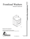
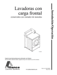
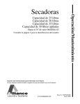
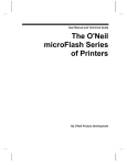
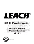
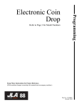
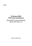
Troubleshooting
Commercial
Frontload
Washers
Refer to Page 6 for Model Numbers
FLW1535C
www.comlaundry.com
Part No. 802740R3
August 2010
Table of
Contents
Section 1 – Safety Information ...............................................................3
Locating an Authorized Servicer...........................................................4
Section 2 – Introduction ..........................................................................5
Customer Service...................................................................................5
Nameplate Location...............................................................................5
Model Identification ..............................................................................6
Theory of Operation
(Coin Slide Operated Models)...............................................................8
Theory of Operation
(Electronic Control Models)................................................................10
Section 3 – General Troubleshooting...................................................12
1. Motor Circuit...............................................................................12
2. Troubleshooting Knocking Noise ...............................................13
3. Troubleshooting Coin Drop ........................................................13
4. No Spin Due to Out-of-Balance Switch Wiring Problem
Starting Serial Nos. Beginning 0307 ..........................................18
5. Troubleshooting LEDs on Inverter Controls Starting
Machine Serial No. 0911014603 ................................................19
6. Vibration .....................................................................................19
7. No Spin .......................................................................................20
Section 4 – Coin Slide Operated Troubleshooting..............................21
8. Coin Slide Can’t Be Fully Inserted .............................................21
9. Coin Slide Switch Not Activated ................................................22
10. Coin Slide Switch Activated Too Soon ......................................23
11. Coin Slide Doesn’t Freely Return...............................................24
12. Error Code Listing ......................................................................25
13. Washer Will Not Start – No LEDs/Lights Lit
(No Response to Start Switch) ....................................................26
14. Washer Will Not Start – No Door Lock
(Door Locked/Close Door LEDs Flashing) ................................28
15. Washer Will Not Start – In Use/Close Door LEDs Flashing
(Door Must Be Closed and Attempting to Lock)........................30
16. Motor Will Not Run
(Door Locked/Final Spin and Tumble LEDs Flashing)..............32
17. Washer Will Not Fill (In Use/Door Locked LEDs Flashing) .....34
18. Washer Overflows.......................................................................36
19. Pump or Drain Valve Does Not Operate ....................................38
20. Serial Communication Error
(Final Spin and Tumble/Close Door LEDs Flashing).................40
Section 5 – NetMaster and MDC Troubleshooting ............................42
21. Error Code Listing ......................................................................42
22. Microwand Does Not Communicate With Control –
NetMaster Models Only..............................................................44
23. Coins Ignored When Entered......................................................45
© Copyright 2010, Alliance Laundry Systems LLC
All rights reserved. No part of the contents of this book may be reproduced or transmitted in any form or by any means without
the expressed written consent of the publisher.
802740
© Copyright, Alliance Laundry Systems LLC – DO NOT COPY or TRANSMIT
1
24.
25.
26.
27.
28.
29.
30.
31.
32.
33.
No Visible Display on Control....................................................46
Washer Will Not Start – “door” Displayed.................................48
Washer Will Not Start – E:dL on Display ..................................50
Washer Will Not Fill (Machine Empty, No E:SP on Display) ...52
Washer Overflows.......................................................................54
Pump or Drain Valve Does Not Operate ....................................56
Serial Communication Error (E:SP on Display) .........................58
Motor Does Not Run (E:df on Display)......................................60
Washer Will Not Heat (“OP” or “SH” Displayed) .....................62
Washer Will Not Heat (Models Equipped with Heater)
(3 Phase Heater Machines Only) ................................................64
Section 6 – Adjustments ........................................................................66
34. Cabinet Leveling Legs ................................................................66
35. Loading Door ..............................................................................67
36. Motor Belt Tension .....................................................................68
37. Door Catch ..................................................................................69
38. Shipping Braces ..........................................................................71
39. Cleaning Non-Electronic Coin Drop...........................................72
40. Cleaning Electronic Coin Drop...................................................74
2
© Copyright, Alliance Laundry Systems LLC – DO NOT COPY or TRANSMIT
802740
Section 1
Safety Information
Throughout this manual and on machine decals, you will find precautionary statements (“CAUTION,”
“WARNING” and “DANGER”) followed by specific instructions. These precautions are intended for the personal
safety of the operator, user, servicer, and those maintaining the machine.
a DANGER
Danger indicates an imminently hazardous situation that, if not avoided, will cause severe personal injury or death.
WARNING
Warning indicates a hazardous situation that, if not avoided, could cause severe personal injury or death.
CAUTION
Caution indicates a hazardous situation that, if not avoided, may cause minor or moderate personal injury or property
damage.
Additional precautionary statements (“IMPORTANT” and “NOTE”) are followed by specific instructions.
IMPORTANT
The word “IMPORTANT” is used to inform the reader of specific procedures where minor machine damage will
occur if the procedure is not followed.
NOTE
The word “NOTE” is used to communicate installation, operation, maintenance or servicing information that is
important but not hazard related.
In the interest of safety, some general precautions relating to the operation of this machine follow.
WARNING
• Failure to install, maintain and/or operate this product according to the manufacturer’s
instructions may result in conditions which can produce serious injury, death and/or property
damage.
• Do not repair or replace any part of the product or attempt any servicing unless specifically
recommended or published in this Service Manual and unless you understand and have the
skills to carry out the servicing.
• Whenever ground wires are removed during servicing, these ground wires must be
reconnected to ensure that the product is properly grounded and to reduce the risk of fire,
electric shock, serious injury or death.
W006R2
802740
© Copyright, Alliance Laundry Systems LLC – DO NOT COPY or TRANSMIT
3
Safety Information
WARNING
To reduce the risk of electric shock, fire, explosion, serious injury or death:
• Disconnect electric power to the washer before servicing.
• Never start the washer with any guards/panels removed.
• Whenever ground wires are removed during servicing, these ground wires must be
reconnected to ensure that the washer is properly grounded.
• Motor not grounded! Disconnect electric power before servicing motor.
W485
WARNING
Repairs that are made to your products by unqualified persons can result in hazards due to
improper assembly or adjustments subjecting you or the inexperienced person making such
repairs to the risk of serious injury, electrical shock or death.
W007
WARNING
If you or an unqualified person perform service on your product, you must assume the
responsibility for any personal injury or property damage which may result. The manufacturer
will not be responsible for any injury or property damage arising from improper service and/or
service procedures.
W008
NOTE: The WARNINGS and IMPORTANT INSTRUCTIONS appearing in this manual are not meant to
cover all possible conditions and situations that may occur. Common sense, caution and care must be
exercised when installing, maintaining or operating the washer.
Always contact your dealer, distributor, service agent or the manufacturer about any problems or conditions you do
not understand.
Locating an Authorized Servicer
Alliance Laundry Systems is not responsible for personal injury or property damage resulting from improper
service. Review all service information before beginning repairs.
Warranty service must be performed by an authorized technician, using authorized factory parts. If service is
required after the warranty expires, Alliance Laundry Systems also recommends contacting an authorized technician
and using authorized factory parts.
4
© Copyright, Alliance Laundry Systems LLC – DO NOT COPY or TRANSMIT
802740
Section 2
Introduction
Customer Service
If literature or replacement parts are required, contact
the source from whom the machine was purchased or
contact Alliance Laundry Systems at (920) 748-3950
for the name and address of the nearest authorized
parts distributor.
For technical assistance, call either of the numbers
listed below:
(920) 748-3121 Ripon, Wisconsin
+32 56 41 20 54 Wevelgem, Belgium
Nameplate Location
When calling or writing about your product, be sure to
mention model and serial numbers. Model and serial
numbers are located on nameplate(s) as shown.
FLW2123N
Nameplate
802740
© Copyright, Alliance Laundry Systems LLC – DO NOT COPY or TRANSMIT
5
Introduction
Model Identification
Information in this manual is applicable to these washers.
Model Number
BFNBEFSP111CN01
X
BFNBEFSP111CW01
X
BFNBEFSP111TN01
X
BFNBEFSP111TW01
X
BFNBLFSP301AW01
X
BWFL74*N4000
X
BWFL75*N4000
X
BWFX71*N1127
X
BWFX71*N3050
X
BWFX74*N4000
X
BWFX75*N4000
X
HFNBCFSG111TN01
X
HFNBCFSP111TN01
X
HFNCXFSP111CW01
X
HFNCXRSP111CW01
X
NetMaster
HWFB71*N
X
HWFB71*N1102
X
HWFR71*N1102
X
HWFT71*N
X
HWFT71*N1102
X
HWFT73*N
X
HWFT73*N1102
X
HWFX71*N1102
X
HWFX71*N1127
X
HWFY71*N1102
X
HWFY73*N1102
X
HWFY74*N4000
X
HWFY75*N4000
X
Coin Slide Operated
HWR971*N1102
X
HWR971*N1127
X
HWR973*N1102
X
HWRR71*N1102
X
HWRT71*N
X
HWRT71*N1102
X
HWRX71*N1102
X
HWRY71*N1102
X
NWFL84*N4000
X
* Add Letter To Designate Color.
6
MDC
N – Stainless Steel
Q – Bisque
W – White
© Copyright, Alliance Laundry Systems LLC – DO NOT COPY or TRANSMIT
802740
Introduction
Model Number
NWFL85*N4000
X
NWFX74*N4000
X
NWFX75*N4000
X
SFNBCRSP111TW02
X
SFNCCFSP111TW01
X
SFNCCRSP111TW01
X
SFNCCRSP111TW02
X
SFNCXRSP111TW02
X
SFNCYFSP111TW01
X
SFNCYRSP111TW01
X
NetMaster
Coin Slide Operated
SFNSXRSP111TW02
X
SFNTXRSP111TW01
X
SFNTXRSP111TW02
X
SWFA71*N
X
SWFA71*N3050
X
SWFA71*N3069
X
SWFA73*N
X
SWFB71*N
X
SWFB72*N
X
SWFB73*N
X
SWFF71*N
X
SWFF71*N3050
X
SWFF73*N
X
SWFL74*N4000
X
SWFT71*N
X
SWFT73*N
X
SWFX71*N
X
SWFX71*N1127
X
SWFX71*N3000
X
SWFX71*N3050
X
SWFX71*N5400
X
SWFX73*N
X
SWFX74*N4000
X
SWFX75*N4000
X
SWFY71*N
X
SWFY73*N
X
SWR971*N
X
SWR973*N
X
SWRB71*N
X
SWRF71*N
X
* Add Letter To Designate Color.
802740
MDC
N – Stainless Steel
Q – Bisque
W – White
© Copyright, Alliance Laundry Systems LLC – DO NOT COPY or TRANSMIT
7
Introduction
Model Number
MDC
SWRT71*N
X
SWRT73*N
X
SWRX71*N
X
SWRY71*N
X
* Add Letter To Designate Color.
N – Stainless Steel
NetMaster
Q – Bisque
Coin Slide Operated
W – White
Theory of Operation
(Coin Slide Operated Models)
Control
(Located in control
hood)
Start
Switch
Pressure Switch
(Located in control
hood)
Temperature
Switch
Speed
Switch
Mixing
Valve
Inner
Basket
Outer
Tub
Motor
Inverter
Control
Electric
Drain Pump
(or Drain Valve)
8
FLW1765S
© Copyright, Alliance Laundry Systems LLC – DO NOT COPY or TRANSMIT
802740
Introduction
General
This frontload washer provides some of the same
principles of operation as the typical topload washers.
It senses water level, it dispenses the desired laundry
detergent, agitates the clothes for good cleaning action,
pumps the water out of the washer and spins the
clothing in preparation for the dryer.
The difference in operation is primarily the rotational
washing agitation created for the horizontal basket and
drum. This agitation tumbles the clothes in a clockwise,
pause, and counter-clockwise direction. This reversing
tumbling action provides an efficient washing process
and requires less laundry detergent and less water.
The cycle begins by pressing the start button, which
locks the loading door after the vend is satisfied. The
type of cycle and water temperature are determined by
the temperature selector switch and the cycle select
switch.
The inner basket starts agitating during the wash water
fill. A column of air is trapped in a pressure bulb and
hose. The air pressure continues to increase as the inner
basket fills with water until it is great enough to
activate the pressure switch which then causes the wash
fill to stop.
The regular and perm press agitate cycle tumble the
clothing in a clockwise direction for a period of 15
seconds, pauses for nine seconds and then tumbles the
clothing in a counterclockwise direction for 15
seconds. This agitation continues until the end of the
wash cycle. The machine stops agitating and turns on
the pump or drain valve which removes the wash water.
Upon completion of the wash cycle, the machine goes
into two rinse cycles. Fresh cold water is brought into
the inner basket via the mixing valve until the pressure
switch shuts off the water while agitating. The rinse
cycle consists of agitation for a predetermined amount
of time, then a spin mode with the pump running while
the machine goes into a series of 4 short 500 RPM
spins.
After all the rinse cycles have been completed, the
washer goes into a final high spin cycle to extract as
much water as possible from the clothing to prepare
them for the dryer. The spin speeds and duration of this
final high spin cycle are determined by the type of wash
cycle selected. Refer to Table 1 or Table 2.
802740
NOTE: Washer may not reach 1000 RPM because
of an out-of balance condition. Control may limit
speed to 850, 650 or 500 RPM depending on severity
of out-of-balance condition.
Models Through Serial No. 0911014602
650
RPM
1000
RPM
Regular
3
minutes
3
minutes
Perm Press
4
minutes
2
minutes
Delicate
4
minutes
0
minutes
Table 1
Models Starting Serial No. 0911014603
500
RPM
650
RPM
1000
RPM
Regular
0
minutes
3
minutes
3
minutes
Perm Press
0
minutes
6
minutes
0
minutes
Delicate
4
minutes
0
minutes
0
minutes
Table 2
Technical
The basic operational system of this washer consists of
the control, temperature switch, inverter control,
pressure switch, water valves, electric pump (or drain
valve), A.C. motor, transformer and cycle select
switch.
The control performs all timing functions like the timer
in a topload washer.
The inverter control uses a speed sensor on the motor
to measure the drum RPM. Before entering any spin
step, the inverter control measures the RPM of motor to
sense out-of-balance. The inverter control will try to
redistribute the clothes if an out-of-balance condition
exists; the inverter control will limit the spin speed to
several speeds depending on the severity of the out-ofbalance condition. If the out-of-balance condition is
severe enough, the inverter control will limit speed to
90 RPM and will not spin.
NOTE: An additional out-of-balance switch is used
to detect any out-of-balance condition during spins.
If this switch opens during a spin step, the inverter
control immediately stops and then restarts the
spin.
© Copyright, Alliance Laundry Systems LLC – DO NOT COPY or TRANSMIT
9
Introduction
Theory of Operation
(Electronic Control Models)
Pressure Switch
(Located inside
control cabinet)
Electronic
Control
(Mounted to back
side of control panel)
3
2
1
Mixing
Valve
Belt
Inner
Basket
Outer
Tub
Inverter Control
(Mounted to base
of washer)
FLW1766S
Electric
Drain Pump
(or Drain Valve)
Motor
General
This frontload washer provides some of the same
principles of operation as the typical topload washers.
It senses water level, it dispenses the desired laundry
detergent, agitates the clothes for good cleaning action,
removes the water out of the washer and spins the
clothing in preparation for the dryer.
The difference in operation is primarily the rotational
washing agitation created for the horizontal basket and
drum. This agitation tumbles the clothes in a clockwise,
10
pause, and counter-clockwise direction. This reversing
tumbling action provides an efficient washing process
and requires less laundry detergent and less water.
The cycle begins by locking the loading door after the
vend is satisfied. The type of cycle and water
temperature are determined by the appropriate pads on
the electronic control.
The inner basket starts agitating during the wash water
fill. A column of air is trapped in a pressure bulb and
hose. The air pressure continues to increase as the inner
© Copyright, Alliance Laundry Systems LLC – DO NOT COPY or TRANSMIT
802740
Introduction
basket fills with water until it is great enough to
activate the pressure switch which then causes the wash
fill to stop.
The agitate cycle tumbles the clothing in a clockwise
direction for a period of 15 seconds, pauses for nine
seconds and then tumbles the clothing in a
counterclockwise direction for 15 seconds. This
agitation continues until the end of the wash cycle. The
machine stops agitating and turns on the pump or drain
valve which removes the wash water.
Upon completion of the wash cycle, the machine goes
into a rinse cycle. Fresh cold water is brought into the
inner basket via the mixing valve until the pressure
switch shuts off the water while agitating. The rinse
cycle consists of agitation for a predetermined amount
of time then a spin mode with the pump running where
the machine goes into a series of 4 short 500 RPM
spins. Two of these rinse cycles will normally take
place with a third extra rinse cycle being optional.
After all the rinse cycles have been completed, the
washer goes into a final high spin cycle to extract as
much water as possible from the clothing to prepare
them for the dryer. The spin speeds and duration of this
final high spin cycle are determined by the type of wash
cycle selected. Refer to Table 3 or Table 4.
NOTE: Washer may not reach 1000 RPM because
of an out-of-balance condition. Control may limit
speed to 850, 650 or 500 RPM depending on severity
of out-of-balance condition.
Models Through Serial No. 0911014602
650
RPM
1000
RPM
Regular
3
minutes
3
minutes
Perm Press
4
minutes
2
minutes
Delicate
4
minutes
0
minutes
Technical
The basic operational system of this washer consists of
the electronic control, the inverter control, pressure
switch, water valves, electric pump (or drain valve)
and A.C. motor.
The electronic control performs all control and timing
functions like the timer in a topload washer. The
electronic control sends simple speed and output
commands to the inverter control via serial
communication. The electronic control powers the
door lock, pump (or drain valve) and the inverter
control.
The inverter control powers the A.C. motor and
performs all motor control functions. The inverter
control also powers the water and dispenser valves and
passes the pressure switch status to the electronic
control. The inverter control is powered through the
door switch, door lock switch and electronic control.
The inverter control also alerts the electronic control to
any errors in the motor.
The inverter control uses a speed sensor on the motor
to measure the drum RPM. Before entering any spin
step the inverter control measures the RPM of the
drum to sense out-of-balance. The inverter control will
try to redistribute the clothes if an out-of-balance
condition exists the inverter control will limit the spin
speed to several speeds depending on the severity of
the out-of-balance condition. If the out-of-balance
condition is severe enough the inverter control will
limit speed to 90 RPM and will not spin.
NOTE: An additional out-of-balance switch is used
to detect any out-of-balance condition during spins.
If this switch opens during a spin step, the inverter
control immediately stops and then restarts the
spin.
Table 3
Models Starting Serial No. 0911014603
500
RPM
650
RPM
1000
RPM
Regular
0
minutes
3
minutes
3
minutes
Perm Press
0
minutes
6
minutes
0
minutes
Delicate
4
minutes
0
minutes
0
minutes
Table 4
802740
© Copyright, Alliance Laundry Systems LLC – DO NOT COPY or TRANSMIT
11
Section 3
General Troubleshooting
WARNING
To reduce the risk of electric shock, fire, explosion, serious injury or death:
• Disconnect electric power to the washer before servicing.
• Never start the washer with any guards/panels removed.
• Whenever ground wires are removed during servicing, these ground wires must be
reconnected to ensure that the washer is properly grounded.
• Motor not grounded! Disconnect electric power before servicing motor.
W485
1. Motor Circuit
Windings
White
Gray
Red
5 4 32 1
Resistance Values:
Tachometer Circuit:
Terminals 4–5
Approx. 115 ohms
12
Red
Red
Tach. Circuit
Windings:
Terminals 1–2, 2–3, 1-3
Approx. 4.5 ohms
© Copyright, Alliance Laundry Systems LLC – DO NOT COPY or TRANSMIT
802740
General Troubleshooting
WARNING
To reduce the risk of electric shock, fire, explosion, serious injury or death:
• Disconnect electric power to the washer before servicing.
• Never start the washer with any guards/panels removed.
• Whenever ground wires are removed during servicing, these ground wires must be
reconnected to ensure that the washer is properly grounded.
• Motor not grounded! Disconnect electric power before servicing motor.
W485
2. Troubleshooting Knocking Noise
3. Troubleshooting Coin Drop
If a frontload washer produces a noise similar to a
knock on a door, it might be due to a flat spot on
the belt. The knocking sound is made when the
flat spot hits the pulley. The knocking may occur
during a pulse spin and fade after reaching a
higher RPM.
a. Non-Electronic Coin Drops:
When coin is placed into coin slot, the coin
should roll down drop and be heard dropping into
coin vault. If coin does not fall into coin vault or
if coin drop sensor does not register that coin has
been entered, follow troubleshooting instructions
on following page. Refer to Figure 1 for path that
coin follows when working properly (nonelectronic coin drops).
To correct this condition, replace the belt.
IMPORTANT: Never use oil to correct coin drop
problems. Oil residue will prevent coins from
rolling properly.
IMPORTANT: Do not bend or damage mechanical
parts within coin drop.
Additional coins
following path to
sensor
Coin in
Coin Slot
Coin Drop
Sensor
DRY2B
Figure 1
802740
© Copyright, Alliance Laundry Systems LLC – DO NOT COPY or TRANSMIT
13
General Troubleshooting
WARNING
To reduce the risk of electric shock, fire, explosion, serious injury or death:
• Disconnect electric power to the washer before servicing.
• Never start the washer with any guards/panels removed.
• Whenever ground wires are removed during servicing, these ground wires must be
reconnected to ensure that the washer is properly grounded.
• Motor not grounded! Disconnect electric power before servicing motor.
W485
3. Troubleshooting Coin Drop (continued)
Is proper
electrical power
supplied to coin drop?
(Incorrect electrical connection
may prevent coins from
registering in
coin drop.)
No
Refer to wiring
diagram for
proper connections.
Yes
Is
machine level?
(Machines that aren't
level may prevent coins from
following through required
check stages
of drop.)
No
Refer to
Installation Instructions
for instructions
on leveling machine.
Yes
Is coin drop
clean? (Residue or
lint build-up may prevent
coins from following through
required check stages
of drop.)
No
Refer to
Adjustments section
for instructions on cleaning
drop.
Yes
Do coins
fall freely
through drop?
No
Replace
coin drop.
Yes
Replace
coin drop sensor.
SWD1714S
14
© Copyright, Alliance Laundry Systems LLC – DO NOT COPY or TRANSMIT
802740
General Troubleshooting
WARNING
To reduce the risk of electric shock, fire, explosion, serious injury or death:
• Disconnect electric power to the washer before servicing.
• Never start the washer with any guards/panels removed.
• Whenever ground wires are removed during servicing, these ground wires must be
reconnected to ensure that the washer is properly grounded.
• Motor not grounded! Disconnect electric power before servicing motor.
W485
b. Electronic Coin Drops:
If coin drop is not accepting coins, perform the
following:
(1) Clean coin drop. Refer to Paragraph 40.
(2) On electronic coin drops with an old-style
tension spring (shown in Figure 2 and
Figure 4), test and replace tension spring
using the following instructions.
Remove Coin Drop From Machine
(1) Disconnect electrical power to machine and
drop.
(2) Remove coin drop from machine.
Test Tension Spring
(1) Push coin return button to open and close
coin drop cover to clear possible coin jams.
Refer to Figure 2.
(3) If coin drop now operates properly, replace
tension spring using instructions on
following pages.
Replace Tension Spring
(1) Move tension spring downward until cover
catch is free. Refer to Figure 4.
Tension Spring
Cover Catch
Coin Drop
Cover
Coin Return
Button
DRY2088N
Figure 4
(2) Open cover for coin drop.
Tension Spring
MIX7B
Figure 2
(2) Manually hold down coin drop cover and
insert coin. Refer to Figure 3.
MIX6B
Coin Drop
Cover
Figure 3
802740
© Copyright, Alliance Laundry Systems LLC – DO NOT COPY or TRANSMIT
15
General Troubleshooting
WARNING
To reduce the risk of electric shock, fire, explosion, serious injury or death:
• Disconnect electric power to the washer before servicing.
• Never start the washer with any guards/panels removed.
• Whenever ground wires are removed during servicing, these ground wires must be
reconnected to ensure that the washer is properly grounded.
• Motor not grounded! Disconnect electric power before servicing motor.
W485
(3) Place a small flathead screwdriver under
right side of tension spring and lift up.
Refer to Figure 5.
(9) Remove clip from spring. Refer to
Figure 7.
Small Flathead
Screwdriver
Clip
MIX4B
Figure 7
Left Tab
Right Side of
Tension Spring
(10) Attach clip to new tension spring, Part No.
209/00598/02.
(11) Place clip, installed on spring, in slot on
coin drop. Refer to Figure 8.
MIX2B
Figure 5
(4) Use screwdriver to move spring
approximately 3 mm to left.
(5) Lift spring over left tab. Refer to Figure 5.
(6) Rotate spring clockwise, 40 to 60 degrees,
until it is free from right tabs. Refer to
Figure 6.
Slot
MIX8B
Tabs
Figure 8
Center Tab
MIX3B
Figure 6
(7) Use screwdriver to remove spring from
center tab. Refer to Figure 6.
(8) Lift spring, with attached clip, off drop.
16
© Copyright, Alliance Laundry Systems LLC – DO NOT COPY or TRANSMIT
802740
General Troubleshooting
WARNING
To reduce the risk of electric shock, fire, explosion, serious injury or death:
• Disconnect electric power to the washer before servicing.
• Never start the washer with any guards/panels removed.
• Whenever ground wires are removed during servicing, these ground wires must be
reconnected to ensure that the washer is properly grounded.
• Motor not grounded! Disconnect electric power before servicing motor.
W485
(12) Use a small flathead screwdriver to push
spring under center tab. Refer to Figure 9.
Reinstall Coin Drop Into Machine
(1) Reinstall coin drop into machine.
(2) Reconnect electrical power to machine and
drop.
(3) Add a coin to drop to verify that coin drop
is operating properly and that electrical
connection is working properly.
Center
Tab
Small Flat
Screwdriver
Left Tab
MIX5B
Figure 9
(13) Lift spring gently to place in position under
left tab.
(14) Push spring to right until it snaps into
position. Refer to Figure 5.
(15) Close coin drop cover.
(16) Move tension spring over cover catch.
Refer to Figure 4.
802740
© Copyright, Alliance Laundry Systems LLC – DO NOT COPY or TRANSMIT
17
General Troubleshooting
WARNING
To reduce the risk of electric shock, fire, explosion, serious injury or death:
• Disconnect electric power to the washer before servicing.
• Never start the washer with any guards/panels removed.
• Whenever ground wires are removed during servicing, these ground wires must be
reconnected to ensure that the washer is properly grounded.
• Motor not grounded! Disconnect electric power before servicing motor.
W485
4. No Spin Due to Out-of-Balance Switch Wiring Problem Starting Serial
Nos. Beginning 0307
A “no spin” condition could be the result of an open circuit in the wire harness or out-of-balance switch. First, check
that the harness is still connected to the out-of-balance switch. The out-of-balance switch is a normally closed
switch. (continued)
45 degrees
Third Section
of Tape 14 In.
(35.56 cm)
From End of
Terminals
Wire Clamp
First Section
of Tape 4.5 In.
(11.43 cm)
From End of
Terminals
Wire Tie
Cut Off
Broken
Wires Here
FLW1842B
Figure 10
18
© Copyright, Alliance Laundry Systems LLC – DO NOT COPY or TRANSMIT
802740
General Troubleshooting
WARNING
To reduce the risk of electric shock, fire, explosion, serious injury or death:
• Disconnect electric power to the washer before servicing.
• Never start the washer with any guards/panels removed.
• Whenever ground wires are removed during servicing, these ground wires must be
reconnected to ensure that the washer is properly grounded.
• Motor not grounded! Disconnect electric power before servicing motor.
W485
If broken wires are found at the out-of-balance switch
wire support, cut off portion of wires as shown in
Figure 10 and add new UL approved terminals.
a. To test the electrical circuit, disconnect
electrical power to the washer.
b. Remove the “H1” connector from the inverter
control assembly.
c. Use an Ohm meter to check the black/white to
violet/white wires. Circuit should read closed.
An open reading indicates a bad switch or
wire harness problem.
d. Flex the harness at the plastic wire clamp and
test continuity. If the base wire harness has an
open circuit it MUST be replaced or the
broken wires must be repaired with UL
approved terminals.
e. After replacing or repairing the wire harness,
wrap electrical tape around wires in two
locations as indicated below and in Figure 10.
Then secure the harness wires to the original
factory locations using clamp and wire tie.
Refer to Figure 10.
(1) The plastic wire clamp should be angled
toward the switch at 45 degrees.
(2) The clamp should wrap around the first
section of tape on the harness, which should
be placed approximately 4.5 inches (11.43
cm) from end of terminals.
(3) The harness should be secured to the
inverter control shield with a wire tie.
(4) The tie should wrap around the third section
of tape on the harness, which should be
placed approximately 14 inches (35.56 cm)
from end of terminals. Refer to Figure 10.
802740
5. Troubleshooting LEDs on
Inverter Controls Starting
Machine Serial No. 0911014603
There are three LEDs on the control to assist with
troubleshooting (refer to Figure 11):
• Green LED on constant = 5VDC power
supply present
• Green LED flashing one second on/one
second off = inverter control power up
• Red LED flashing four times/second =
inverter control is communicating with
front end control
LEDs
FLW1844B
Figure 11
6. Vibration
If frontload washer vibrates or shakes, refer to
additional leveling procedure in Paragraph 34.
© Copyright, Alliance Laundry Systems LLC – DO NOT COPY or TRANSMIT
19
General Troubleshooting
WARNING
To reduce the risk of electric shock, fire, explosion, serious injury or death:
• Disconnect electric power to the washer before servicing.
• Never start the washer with any guards/panels removed.
• Whenever ground wires are removed during servicing, these ground wires must be
reconnected to ensure that the washer is properly grounded.
• Motor not grounded! Disconnect electric power before servicing motor.
W485
7. No Spin
A no spin condition is not caused by intermittent operation of the motor or motor control (inverter assembly). DO
NOT replace these components for no spin complaints if the unit passes the following procedure:
No spin.
BEFORE replacing
the motor control
board, conduct the
following tests.
Is load
out-ofbalance?
Yes
Unit makes three
attempts to rebalance out-ofbalance loads. If all
attempts fail, final
high speed spin is
aborted. ONLY
proper loading can
correct problem.
No
Is there a slow
drain, clogged
pump or
oversudsing
condition?
No
Yes
Pressure switch
must register an
"empty" condition
before unit will
enter spin. Clear
drain or pump.
Allow unit to go
through complete
final spin cycle.
Does unit spin at
high speed?
Motor and
motor control
Yes board are
operating
properly. Do
not replace
them.
No
Check for broken out-ofbalance switch wires.
Refer to No Spin Due to
Out-of-Balance Switch
Wiring Problem Starting
Serial Nos. Beginning
0307 paragraph.
Does unit
spin now?
No
With no load, rapid
advance to final spin
or select spin only
cycle. Close door
and start washer.
Is pressure
switch or
pressure
switch wiring
inoperative?
Yes
Replace switch
and/or wiring.
FLW1789S
20
© Copyright, Alliance Laundry Systems LLC – DO NOT COPY or TRANSMIT
802740
Section 4
Coin Slide Operated Troubleshooting
WARNING
To reduce the risk of electric shock, fire, explosion, serious injury or death:
• Disconnect electric power to the washer before servicing.
• Never start the washer with any guards/panels removed.
• Whenever ground wires are removed during servicing, these ground wires must be
reconnected to ensure that the washer is properly grounded.
• Motor not grounded! Disconnect electric power before servicing motor.
W485
8. Coin Slide Can’t Be Fully Inserted
Coin slide can't be
fully inserted.
Make sure switch
activation lever is off
switch when installing
coin slide.
Are wires
and/or shield
from control
board interfering
with coin slide
movement?
Yes
Reposition wires
and/or shield.
No
Is coin slide
installed
correctly?
802740
No
Refer toInstallation
manual. Make sure
all four mount screws
are engaged into
meter case opening.
Tighten extension rod
correctly.
TLW1836B
© Copyright, Alliance Laundry Systems LLC – DO NOT COPY or TRANSMIT
21
Coin Slide Operated Troubleshooting
9. Coin Slide Switch Not Activated
Switch isn't activated when coin
slide is fully inserted.
Was the wrong
extension lever
setup used?
Yes
Make sure one or two
stars, depending on
type of coin slide,
face down. Refer to
Installation manual.
Is wiring
connected
correctly?
No
Examine wiring
and terminals
for proper
connections.
Refer to wiring
diagram.
No
Is the switch
activation lever
bent or out of
position?
Yes
Correct lever or
replace switch
mount assembly.
No
Are coin slide
extension lever
and flat washers
(shims) installed
correctly?
No
Refer to Installation
manual. Extension
lever should rotate
freely after assembly.
Extension lever
shouldn't have
excess play.
Yes
Switch activation
lever doesn't rotate
under the force of
the coin slide
extension lever?
Yes
Friction wave
washer in switch
mount assembly
is too tight.
Compress wave
washer slightly
and retest, or
replace switch
mount assembly.
No
TLW1837B
22
© Copyright, Alliance Laundry Systems LLC – DO NOT COPY or TRANSMIT
802740
Coin Slide Operated Troubleshooting
10. Coin Slide Switch Activated Too Soon
Switch is activated
too soon.
Is the switch
activation lever
bent or out of
position?
Yes
Correct lever
or replace
switch mount
assembly.
No
Does the switch
activation lever
rotate freely?
Yes
Replace
switch mount
assembly.
No
Was the wrong
extension lever
setup used?
Yes
Make sure one or two
stars, depending on
type of coin slide,
face down. Refer to
Installation manual.
TLW1838B
802740
© Copyright, Alliance Laundry Systems LLC – DO NOT COPY or TRANSMIT
23
Coin Slide Operated Troubleshooting
11. Coin Slide Doesn’t Freely Return
Coin slide doesn't freely return.
Consult coin slide
manufacturer
instructions, clean and
lubricate coin slide,
double check that return
springs are present.
Was the
wrong
extension
lever setup
used?
Yes
Make sure one
or two stars,
depending on
type of coin
slide, face
down. Refer to
Installation
manual.
No
Are coin slide
switch and
extension
assemblies
equipped with
updated parts?
No
Replace with
assemblies
that have
nitrocarburized
brackets and
lighter spring
with open
hooks.
Is there a
burr present
on extension
lever or
switch
bracket?
Yes
Remove burr,
lubricate and
retest.
Yes
Review
extension lever
for proper free
rotation.
TLW1839B
24
© Copyright, Alliance Laundry Systems LLC – DO NOT COPY or TRANSMIT
802740
Coin Slide Operated Troubleshooting
12. Error Code Listing
If any of the following errors occur, the control
enters Error Mode. For all fatal errors, the control
will terminate the current cycle, turn off all
outputs, and flash two LEDs one second on/one
second off to indicate the error. Refer to the chart
below for which lights flash for each error.
DOOR LOCKED and
FINAL SPIN AND
TUMBLE LEDs
flashing (Motor
Failure Error)
If the control receives the motor failure signal from the motor control, the control will enter
Error Mode. The control will turn off all outputs and flash the DOOR LOCKED and FINAL
SPIN AND TUMBLE LEDs one second on/one second off to indicate a motor failure error.
This is a fatal error. The machine must be unpowered to clear this error.
IN USE and DOOR
LOCKED LEDs
flashing
(Fill Error)
If the control receives no full input from the pressure switch indicating the cylinder is full
within 30 minutes of starting the fill, the control will enter Error Mode. The control will
turn off all outputs and flash the IN USE and DOOR LOCKED LEDs one second on/one
second off to indicate a fill error. This is a fatal error. The machine must be unpowered to
clear this error.
If the control senses the door open during Run Mode, the control will enter Error Mode.
IN USE and CLOSE
The control will turn off all outputs and flash the IN USE and CLOSE DOOR LEDs one
DOOR LEDs flashing
second on/one second off to indicate a door open error. This is a fatal error. The machine
(Door Open Error)
must be unpowered to clear this error.
If the door doesn’t lock in 15 seconds in Door Locking Mode or the door doesn’t unlock in
3 minutes in Door Unlocking Mode, the control will enter Door Lock Error Mode. The
DOOR LOCKED and control will turn off all outputs and flash the DOOR LOCKED and CLOSE DOOR LEDs
one second on/one second off to indicate a door lock/unlock error.
CLOSE DOOR
LEDs flashing
To clear this error in Door Locked Mode the door must either open or lock. If the door locks,
(Door Lock/Unlock
the cycle will start normally. If the door opens, the control will revert back to Start Mode.
Error)
To clear this error in Door Unlocking Mode the door must unlock or open. If the door
unlocks or opens, the control will enter End of Cycle Mode.
FINAL SPIN AND
TUMBLE and
CLOSE DOOR
LEDs flashing
(SPI Communications
Error)
802740
This error occurs when there is a problem with communications between the front-end
control and the motor control. The control will turn off all outputs and flash the FINAL
SPIN AND TUMBLE and CLOSE DOOR LEDs one second on/one second off to indicate
an SPI communications error. This is a fatal error. The machine must be powered down at
this point.
© Copyright, Alliance Laundry Systems LLC – DO NOT COPY or TRANSMIT
25
Coin Slide Operated Troubleshooting
13. Washer Will Not Start – No LEDs/Lights Lit (No Response to Start Switch)
(1)
Is there 120 VAC
to control
Transformer?
No
Check wiring
to transformer.
No
Replace
transformer.
Yes
(2)
Is there 24 VAC
from "H1-1" to "H1-3"
on the machine control ?
Yes
(3)
Is there
continuity across
"H3-1" and "H3-2" on
the machine control when
the coin slide is
pushed in?
No
Check wiring
between
coin slide switch
and machine
control.
Yes
(4)
Is there
continuity across
"H9-3" to "H9-7" on
the machine control when
the start switch is
depressed?
No
Correct wiring
to and/or replace
start switch.
Yes
Replace machine
control.
FLW1725S
26
© Copyright, Alliance Laundry Systems LLC – DO NOT COPY or TRANSMIT
802740
Coin Slide Operated Troubleshooting
1
2
4
3
Washer Will Not Start – No LEDs/Lights Lit (No Response to Start Switch)
802740
© Copyright, Alliance Laundry Systems LLC – DO NOT COPY or TRANSMIT
27
Coin Slide Operated Troubleshooting
14. Washer Will Not Start – No Door Lock (Door Locked/Close Door LEDs
Flashing)
(1)
Is there 120 Volts
at machine control
terminals
"H4-5" to "H6-5"?
No
Check door switch,
door strike adjustment,
and/or wiring.
Replace door lock if
necessary.
Yes
(2)
Is there 120 Volts
at machine control
terminals
"H4-4" to "H6-5"?
No
Replace machine
control.
Yes
(3)
Is there
120 Volts
at the door lock
between the WHT/RED
and the PNK/BLK
wires?
No
Correct wiring
between machine
control and door
lock assembly.
Yes
Replace door
lock assembly.
FLW1778S
28
© Copyright, Alliance Laundry Systems LLC – DO NOT COPY or TRANSMIT
802740
Coin Slide Operated Troubleshooting
1
2
3
Washer Will Not Start – No Door Lock (Door Locked/Close Door LEDs Flashing)
802740
© Copyright, Alliance Laundry Systems LLC – DO NOT COPY or TRANSMIT
29
Coin Slide Operated Troubleshooting
15. Washer Will Not Start – In Use/Close Door LEDs Flashing (Door Must Be
Closed and Attempting to Lock)
Washer will not start.
Vend satisfied.
(1)
Is there 120 VAC
across "H4-5" to "H6-5"
on the machine
control?
Yes
Replace machine
control.
Yes
Replace the door
lock assembly.
Yes
Replace the
door switch.
No
(2)
Is there 120 VAC
from the red wire
on door lock assembly
to neutral?
No
(3)
Is there
120 VAC from
the blk wire on the
door switch
to neutral?
No
Correct wiring
to the
door switch.
FLW1769S
30
© Copyright, Alliance Laundry Systems LLC – DO NOT COPY or TRANSMIT
802740
Coin Slide Operated Troubleshooting
1
3
2
Washer Will Not Start – In Use/Close Door LEDs Flashing (Door Must Be Closed
and Attempting to Lock)
802740
© Copyright, Alliance Laundry Systems LLC – DO NOT COPY or TRANSMIT
31
Coin Slide Operated Troubleshooting
16. Motor Will Not Run (Door Locked/Final Spin and Tumble LEDs Flashing)
(1)
Is there
continuity between
motor terminals?
Refer to values
at right.
Yes
Replace motor
control.
Motor Resistance Values:
Tach. Circuit: Approx. 115 ohms (Terminals 4-5)
Windings: Approx. 4 - 5 ohms (Terminals 1-2, 1-3, 2-3)
No
Replace motor.
FLW1712S
32
© Copyright, Alliance Laundry Systems LLC – DO NOT COPY or TRANSMIT
802740
Coin Slide Operated Troubleshooting
1
Motor Will Not Run (Door Locked/Final Spin and Tumble LEDs Flashing)
802740
© Copyright, Alliance Laundry Systems LLC – DO NOT COPY or TRANSMIT
33
Coin Slide Operated Troubleshooting
17. Washer Will Not Fill (In Use/Door Locked LEDs Flashing)
No
Is the door
locked?
Refer to section:
Washer Will Not Start No Door Lock .
Yes
(1)
Is there
120 Volts at
terminals "H9-4" and
"H1-1" on the
motor control
board?
(2)
Is there
120 Volts between
the BRN/YEL wire on the
pressure switch and
"H6-5" on machine
control?
No
No
Correct wiring
between machine
control and
pressure switch.
Yes
Yes
Replace
pressure
switch.
(3)
Is there
120 Volts at
terminals "H9-1" to
"H1-1" on the motor
control board?
No
Replace
pressure
switch.
No
Replace
motor
control.
Yes
(4)
Is there
120 Volts
at the
mixing valve?
Yes
Replace mixing
valve.
34
© Copyright, Alliance Laundry Systems LLC – DO NOT COPY or TRANSMIT
FLW1713S
802740
Coin Slide Operated Troubleshooting
2
1
4
3
Washer Will Not Fill (In Use/Door Locked LEDs Flashing)
802740
© Copyright, Alliance Laundry Systems LLC – DO NOT COPY or TRANSMIT
35
Coin Slide Operated Troubleshooting
18. Washer Overflows
Washer Overflows
(1)
Is there
120 Volts at the
over level terminal on
pressure switch to "H6-5"
on machine
control?
No
Replace
inoperative
pressure switch.
Yes
(2)
Is there 120 Volts
across the coil of
either the hot or cold
water solenoid?
Yes
Check for
improper wiring
and replace
inoperative
pressure switch
if necessary.
No
Replace
inoperative
mixing valve.
FLW1665S
36
© Copyright, Alliance Laundry Systems LLC – DO NOT COPY or TRANSMIT
802740
Coin Slide Operated Troubleshooting
1
2
Washer Overflows
802740
© Copyright, Alliance Laundry Systems LLC – DO NOT COPY or TRANSMIT
37
Coin Slide Operated Troubleshooting
19. Pump or Drain Valve Does Not Operate
NOTE: Check at beginning of spin/drain portion of cycle.
Pump or Drain Valve Does Not Operate
(1)
NOTE: Check at
beginning of spin/drain
portion of cycle.
Is there
120 Volts
across the WHT/BLK and
the WHT wire going to
the pump or drain
valve?
Yes
If the pump or
drain valve does not
operate check for
obstruction and
replace if necessary.
No
(2)
Is there
120 Volts from
"H6-2" to "H6-5" on the
machine control?
Yes
Correct wiring
between pump or
drain valve and
machine control.
No
Replace
machine control.
FLW1666S
38
© Copyright, Alliance Laundry Systems LLC – DO NOT COPY or TRANSMIT
802740
Coin Slide Operated Troubleshooting
2
1
Pump or Drain Valve Does Not Operate
802740
© Copyright, Alliance Laundry Systems LLC – DO NOT COPY or TRANSMIT
39
Coin Slide Operated Troubleshooting
20. Serial Communication Error (Final Spin and Tumble/Close Door LEDs
Flashing)
(1)
Is the fuse loose
or blown on the motor
control board?
Yes
Tighten fuse holder
and/or replace fuse.
No
(2)
*Is there
120 VAC across
terminals "H1-1" and "H1-3"
on motor control
board?
(3)
No
*Is there
120 VAC across
terminals "H6-5" and "H6-6"
on machine
control?
No
Replace
machine
control.
Yes
Yes
Correct wiring
between machine
control and motor
control.
(4)
(4)
Is there
continuity through
each wire of the harness
from "H2" on the machine
control to "H7" on the
motor control?
Yes
Replace motor
control.
No
Replace the
harness.
FLW1714S
*NOTE: Machine must be restarted to check voltage.
Voltage is intermittently present for the first 15 seconds,
until error mode is displayed.
40
© Copyright, Alliance Laundry Systems LLC – DO NOT COPY or TRANSMIT
802740
Coin Slide Operated Troubleshooting
3
4
2
1
Serial Communication Error (Final Spin and Tumble/Close Door LEDs Flashing)
802740
© Copyright, Alliance Laundry Systems LLC – DO NOT COPY or TRANSMIT
41
Section 5
NetMaster and MDC Troubleshooting
WARNING
To reduce the risk of electric shock, fire, explosion, serious injury or death:
• Disconnect electric power to the washer before servicing.
• Never start the washer with any guards/panels removed.
• Whenever ground wires are removed during servicing, these ground wires must be
reconnected to ensure that the washer is properly grounded.
• Motor not grounded! Disconnect electric power before servicing motor.
W485
21. Error Code Listing
E:df
Drive failure.
This error code is generated by the motor control and
transmitted to the master control. Several conditions can
cause this code; motor unplugged, motor failure, tachometer
circuit open, inner basket locked up. This is a fatal error.
Machine must be unpowered to reset.
Serial communication error.
This error code occurs when the master control cannot
communicate with the motor control. The master control will
try to reset the motor control by powering it down. It will try
resetting three times before setting the error code. Common
causes: fuse blown on motor control board, wiring to motor
control incorrect. This is a fatal error.
Fill error.
This error code occurs if the pressure switch fails to open in
30 minutes in any fill/agitate cycle. This is a fatal error.
Door open indicator.
This error code occurs when the door is not closed at the start
of an active cycle. If the door is closed, check for wiring or
door switches.
Door open error.
This error code occurs if the control detects the door open and
door locked inputs high at the same time. You can get this
error if you jerk on the door when it is locked or as it is about
to lock. This is a fatal error.
Door lock error.
This error code occurs if the door does not lock in 15 seconds
or unlock in 3 minutes at the end of the cycle. This is a nonfatal error. If the door locks or unlocks while E:dL is
displayed it will clear the error condition. Also if the door is
opened after failing to lock it will clear the display.
Heater error.
This error code occurs if it takes more than two hours to heat
water to the programmed temperature. The cycle will
continue. The code will clear when control exits End of Cycle
mode.
E:SP
E:FL
door
E:do
E:dL
E:Ht
(models
equipped
with heater)
(continued)
42
© Copyright, Alliance Laundry Systems LLC – DO NOT COPY or TRANSMIT
802740
NetMaster and MDC Troubleshooting
OP
(models
equipped
with heater)
Open thermistor error.
This error code occurs if the thermistor circuit opens while
heating.
SH
(models
equipped
with heater)
Shorted thermistor error.
This error code occurs if the thermistor circuit is shorted
while heating.
802740
© Copyright, Alliance Laundry Systems LLC – DO NOT COPY or TRANSMIT
43
NetMaster and MDC Troubleshooting
22. Microwand Does Not Communicate With Control – NetMaster Models
Only
Microwand Does Not Communicate With Control.
Attempt to communicate with the
electronic control from the Microwand.
Is there
acknowledgement of
any kind from the
control?
No
Aim the
Microwand closer
and try again.
Yes
Does the Microwand
prompt: Control
Mismatch error ?
Is there any control
response?
No
Yes
Yes
Make sure
Microwand
selection was for
the proper
machine type and
control generation
type.
Check the following:
- Microwand battery voltage
- Blockage of IR window on control
- Attachment of IR cup to
Microwand.
No
Does the electronic
control display "E:OF"
or "-C-"?
-C-
Communication
sequence checks
out properly.
E:OF
Has IR communication
been turned off?
Yes
Turn IR
communication on
(refer to
programming
manual).
No
Change electronic
control and repeat
procedure.
FLW296S
44
© Copyright, Alliance Laundry Systems LLC – DO NOT COPY or TRANSMIT
802740
NetMaster and MDC Troubleshooting
23. Coins Ignored When Entered
Coins Ignored When Entered.
MDC Models: Start Production
Test Cycle and advance to
Coin Drop step.
Does the count on
the display increment
properly after entering
coins?
Yes
Reset control to
ready mode.
No
Is "H7" connector
properly seated on the
control board?
No
Properly reseat
connection and
conduct diagnostic
test again.
Yes
From the coin drop, is
the 3-pin connector
properly plugged in?
Yes
Are the wires exiting the
coin drop optical sensor
cracked or broken?
No
Properly reseat
connection and
conduct diagnostic
test again.
Yes
No
Replace the
coin drop.
Replace electronic
control.
FLW1704S
802740
© Copyright, Alliance Laundry Systems LLC – DO NOT COPY or TRANSMIT
45
NetMaster and MDC Troubleshooting
24. No Visible Display on Control
Control Has No Visible Display
The electronic control has no
LED or VFD functioning on
the control board.
Is the power cord
plugged in?
No
Plug unit into an
outlet and check
for proper supply
voltage.
Yes
1
2
Is there 24 Volt AC
across terminals "H1-1"
and "H1-3" control
board?
3
(2)
(1)
No
Yes
Is there 24 Volt
AC at the output side of
the transformer?
Yes
Make sure "H1"
connector is
seated properly.
Replace control.
Correct wiring
between
transformer and
control board.
(3)
No
Is there
220-240 VAC
(or 120 VAC)* to the
primary of the
transformer?
No
Check wiring to
the primary of the
transformer.
Yes
Replace
transformer.
FLW1695S
*Refer to machine serial plate for correct voltage.
46
© Copyright, Alliance Laundry Systems LLC – DO NOT COPY or TRANSMIT
802740
NetMaster and MDC Troubleshooting
No Visible Display on Control
3
220-240 VAC (or 120 VAC) 50/60 Hz (SEE MACHINE SERIAL PLATE)
2
1
(Models
with
220240
VAC)
802740
© Copyright, Alliance Laundry Systems LLC – DO NOT COPY or TRANSMIT
47
NetMaster and MDC Troubleshooting
25. Washer Will Not Start – “door” Displayed
Washer Will Not Start. No Door Lock.
Washer will not
start. Vend
satisfied.
1
(1)
Is there
220-240 VAC
(or 120 VAC)*
across "H4-5" and "H6-5"
on the control
board?
Yes
Replace the
electronic
Control Board.
Yes
Replace the Door
Lock Assembly.
No
2
(2)
Is there
220-240 VAC (or
120 VAC)* to the blk
input wire to the door
switch on the lock
assembly?
No
Correct wiring
to the
door switch.
FLW1767S
*Refer to machine serial plate for correct voltage.
48
© Copyright, Alliance Laundry Systems LLC – DO NOT COPY or TRANSMIT
802740
NetMaster and MDC Troubleshooting
Washer Will Not Start – “door” Displayed
220-240 VAC (or 120 VAC) 50/60 Hz (SEE MACHINE SERIAL PLATE)
2
1
(Models
with
220240
VAC)
802740
© Copyright, Alliance Laundry Systems LLC – DO NOT COPY or TRANSMIT
49
NetMaster and MDC Troubleshooting
26. Washer Will Not Start – E:dL on Display
Washer will
not start.
Vend satisfied.
1
(1)
Is there
220-240 VAC (or
120 VAC)* across terminals
"H4-4" and "H6-5" on the
electronic control?
No
Replace the electronic
control board.
Yes
Is door catch
properly adjusted?
Refer to Adjustments
section.
No
Adjust catch and retest.
Yes
Replace the
door lock
assembly.
*Refer to machine serial plate for correct voltage.
FLW1773S
50
© Copyright, Alliance Laundry Systems LLC – DO NOT COPY or TRANSMIT
802740
NetMaster and MDC Troubleshooting
Washer Will Not Start – E:dL on Display
220-240 VAC (or 120 VAC) 50/60 Hz (SEE MACHINE SERIAL PLATE)
1
(Models
with
220240
VAC)
802740
© Copyright, Alliance Laundry Systems LLC – DO NOT COPY or TRANSMIT
51
NetMaster and MDC Troubleshooting
27. Washer Will Not Fill (Machine Empty, No E:SP on Display)
Washer Will Not Fill
(Machine empty, No E:SP on display)
Refer to
Washer Will Not Start E:dL on display
section
No
Is the door
locked?
Yes
1
(1)
Is there
220-240 VAC (or
120 VAC)* across terminals
"H1-1" and "H9-4" on
the motor
control?
No
Correct wiring from
pressure switch or
replace pressure
switch.
Yes
2
(2)
Is there
220-240 VAC
(or 120 VAC)* across
terminals "H9-6" to "H1-1"
(hot) and "H9-3"
to "H1-1"
(cold)?
No
Replace motor
control board.
No
Replace motor
control.
Yes
3
(3)
Is there
220-240 VAC
(or 120 VAC)* across
mixing valve
solenoid(s)?
Yes
Replace mixing
valve.
*Refer to machine serial plate for correct voltage.
FLW1698S
52
© Copyright, Alliance Laundry Systems LLC – DO NOT COPY or TRANSMIT
802740
NetMaster and MDC Troubleshooting
Washer Will Not Fill (Machine empty, No E:SP on Display)
220-240 VAC (or 120 VAC) 50/60 Hz (SEE MACHINE SERIAL PLATE)
(Models
with
220240
VAC)
3
1
2
802740
2
© Copyright, Alliance Laundry Systems LLC – DO NOT COPY or TRANSMIT
53
NetMaster and MDC Troubleshooting
28. Washer Overflows
Washer Overflows
1
(1)
Is there
220-240 VAC
(or 120 VAC)*
to the over level terminal
on pressure switch
to neutral?
No
Replace
inoperative
pressure switch.
Yes
2
(2)
Is there
220-240 VAC
(or 120 VAC)*
across the coil of either
the hot or cold water
solenoid?
Yes
Check for
improper wiring
and replace
inoperative
pressure switch
if necessary.
No
Replace
inoperative water
valve.
*Refer to machine serial plate for correct voltage.
FLW1699S
54
© Copyright, Alliance Laundry Systems LLC – DO NOT COPY or TRANSMIT
802740
NetMaster and MDC Troubleshooting
Washer Overflows
220-240 VAC (or 120 VAC) 50/60 Hz (SEE MACHINE SERIAL PLATE)
(Models
with
220240
VAC)
1
2
2
802740
© Copyright, Alliance Laundry Systems LLC – DO NOT COPY or TRANSMIT
55
NetMaster and MDC Troubleshooting
29. Pump or Drain Valve Does Not Operate
NOTE: Check at beginning of spin/drain portion of cycle.
Pump Does Not Operate
(1)
Is there
220-240 VAC
(or 120 VAC)* across the
wht/blk and the white wire
going to the pump or
drain valve?
Yes
If the pump or
drain valve does not
operate check for
blockage. Replace
if necessary.
No
(2)
Is there
220-240 VAC
(or 120 VAC)*
across terminals
"H6-2" and
"H6-5?"
Yes
Correct wiring
between control
and pump or
drain valve.
No
Replace control
assembly.
*Refer to machine serial plate for correct voltage.
FLW1700S
56
© Copyright, Alliance Laundry Systems LLC – DO NOT COPY or TRANSMIT
802740
NetMaster and MDC Troubleshooting
Pump or Drain Valve Does Not Operate
220-240 VAC (or 120 VAC) 50/60 Hz (SEE MACHINE SERIAL PLATE)
(Models
with
220240
VAC)
1
2
802740
© Copyright, Alliance Laundry Systems LLC – DO NOT COPY or TRANSMIT
57
NetMaster and MDC Troubleshooting
30. Serial Communication Error (E:SP on Display)
SERIAL COMMUNICATION ERROR (E:SP on display
1
(1)
Is the fuse loose or
blown on the motor
control board?
Yes
Tighten fuse
holder and/or
replace fuse.
No
2
(2)
Restart
machine and
check voltage: Is
there 220-240 VAC (or
120 VAC)* across terminals
"H1-1" and "H1-3"
on motor
control?**
3
No
(3)
Restart
machine and
check voltage: Is
there 220-240 VAC (or
120 VAC)* across terminals
"H6-5" and "H6-6"
on the electronic
control?**
Yes
No
Replace
electronic
control.
Yes
Correct wiring from
electronic control to
motor control.
4
(4)
Is there
continuity through
each wire of the harness
from H2 on the electronic
control to H7 on the
motor control?
Yes
Change the
motor control.
No
Change the
harness.
*Refer to machine serial plate for correct voltage.
**NOTE: Machine must be restarted to check voltage.
Voltage will be intermittently present during first 15
seconds until E:SP is displayed.
58
FLW1701S
© Copyright, Alliance Laundry Systems LLC – DO NOT COPY or TRANSMIT
802740
NetMaster and MDC Troubleshooting
Serial Communication Error (E:SP on Display)
220-240 VAC (or 120 VAC) 50/60 Hz (SEE MACHINE SERIAL PLATE)
(Models
with
220240
VAC)
3
4
1
2
802740
© Copyright, Alliance Laundry Systems LLC – DO NOT COPY or TRANSMIT
59
NetMaster and MDC Troubleshooting
31. Motor Does Not Run (E:df on Display)
Motor does not run (E:df on display)
1
(1)
Is there
continuity between
motor terminals?
Refer to values
at right.
Yes
Check motor
plug or replace
motor control.
Motor Resistance Values:
Tach. Circuit: Approx. 115 ohms (Terminals 4-5)
Windings: Approx. 4 - 5 ohms (Terminals 1-2, 1-3, 2-3)
No
Replace motor .
FLW1702S
60
© Copyright, Alliance Laundry Systems LLC – DO NOT COPY or TRANSMIT
802740
NetMaster and MDC Troubleshooting
Motor Does Not Run (E:df on Display)
220-240 VAC (or 120 VAC) 50/60 Hz (SEE MACHINE SERIAL PLATE)
(Models
with
220240
VAC)
1
802740
© Copyright, Alliance Laundry Systems LLC – DO NOT COPY or TRANSMIT
61
NetMaster and MDC Troubleshooting
32. Washer Will Not Heat (“OP” or “SH” Displayed)
1
(1)
Measure
resistance at
connector "H3" on
electronic control. Is resistance
value between
500 and 35,000
ohms?
Yes
Replace electronic
control.
No
2
(2)
Measure
resistance at
thermistor. Is resistance
value between
500 and 35,000
ohms?
No
Replace thermistor/
heater assembly.
Yes
Check wiring
to thermistor.
FLW1705S
62
© Copyright, Alliance Laundry Systems LLC – DO NOT COPY or TRANSMIT
802740
NetMaster and MDC Troubleshooting
Washer Will Not Heat (“OP” or “SH” Displayed)
2
1
802740
© Copyright, Alliance Laundry Systems LLC – DO NOT COPY or TRANSMIT
63
NetMaster and MDC Troubleshooting
33. Washer Will Not Heat (Models Equipped with Heater) (3 Phase Heater
Machines Only)
Is the
pressure switch
satisfied?
No
The heater will not
come on until the
pressure switch
is satisfied.
Yes
Are there
4 "dashes" on
display indicating
the machine
is heating?
No
Verify water temperature
is less than selected
cycle temperature
set point.
Yes
1
(1)
Is there
230 Volts across
the heaters?
Yes
Replace
heater(s).
No
2
(2)
Is there
230 volts across
terminals A1 - A2 on
the heat relay?
No
Correct wiring between
the heat relay coil and
the electronic control
or replace board.
Yes
Check wiring or
replace heat relay.
FLW1703S
64
© Copyright, Alliance Laundry Systems LLC – DO NOT COPY or TRANSMIT
802740
NetMaster and MDC Troubleshooting
Washer Will Not Heat (Models Equipped with Heater) (3 Phase Heater Machines Only)
2
1
1
1
802740
1
1
1
© Copyright, Alliance Laundry Systems LLC – DO NOT COPY or TRANSMIT
65
Section 6
Adjustments
WARNING
To reduce the risk of electric shock, fire, explosion, serious injury or death:
• Disconnect electric power to the washer before servicing.
• Never start the washer with any guards/panels removed.
• Whenever ground wires are removed during servicing, these ground wires must be
reconnected to ensure that the washer is properly grounded.
• Motor not grounded! Disconnect electric power before servicing motor.
W485
IMPORTANT: When reference is made to
directions (right or left) in this manual, it is from
operator’s position facing front of washer.
e. Tighten the locknuts securely against the
washer base. If the locknuts are not tight,
washer will move out of position during
operation.
34. Cabinet Leveling Legs
a. Place washer in position on a solid, sturdy and
level floor. Installing the washer on any type
of carpeting, soft tile, a platform, or other
weak support structures is not recommended.
b. Place level on washer, refer to Figure 12, and
check if washer is level from side to side and
front to back.
CAUTION
DO NOT slide washer across floor if the
leveling legs have been extended, as legs
and base could become damaged.
W248
CAUTION
NOTE: Level must rest on raised portion of top
panel. Refer to Figure 12.
c. If washer is not level, tilt washer to access
front and rear leveling legs. For easier access
to leveling legs, prop up washer with wooden
block. Refer to Figure 12.
d. Loosen locknuts and adjust the leveling legs
until the washer is level from side to side and
front to back (using a level). Make sure
washer does not rock. Refer to Figure 12.
Locknut
Leveling
Leg
Use of the dispenser drawer or washer door
as a handle in the transportation of the
washer may cause damage to the dispenser
or door.
W185
f. Place rubber feet on all four leveling legs.
Refer to Figure 12.
g. Verify that washer doesn’t rock.
Level
Washer
Base
Locknut
Leveling
Leg
Rubber
Foot
Wood Block
Washer
Base
Rubber
Foot
FLW2114N
FRONT CONTROL WASHERS
Level
Wood Block
FLW2125N
REAR CONTROL WASHERS
Figure 12
66
© Copyright, Alliance Laundry Systems LLC – DO NOT COPY or TRANSMIT
802740
Adjustments
WARNING
To reduce the risk of electric shock, fire, explosion, serious injury or death:
• Disconnect electric power to the washer before servicing.
• Never start the washer with any guards/panels removed.
• Whenever ground wires are removed during servicing, these ground wires must be
reconnected to ensure that the washer is properly grounded.
• Motor not grounded! Disconnect electric power before servicing motor.
W485
h. If unit vibrates or shakes during operation,
follow additional leveling procedure below. It
is especially effective if unit is installed on
uneven, non-concrete surface.
i. Loosen one front leveling leg locknut. Refer
to Figure 12.
j. Run cycle with unbalanced load (single pair
of blue jeans or knotted towels).
k. During 1000 RPM spin, adjust leg up or down
by turning it 1/8 turn until washer’s vibration
is reduced and washer is at its most stable
point.
l. Re-tighten locknut.
35. Loading Door
a. Open loading door.
b. The loading door can be adjusted up or down
somewhat by loosening screws holding door
hinge to front panel, then raise or lower door
before retightening screws. Refer to Figure
13.
Hinge
Loading
Door
Screw
FLW1771S
Figure 13
802740
© Copyright, Alliance Laundry Systems LLC – DO NOT COPY or TRANSMIT
67
Adjustments
WARNING
To reduce the risk of electric shock, fire, explosion, serious injury or death:
• Disconnect electric power to the washer before servicing.
• Never start the washer with any guards/panels removed.
• Whenever ground wires are removed during servicing, these ground wires must be
reconnected to ensure that the washer is properly grounded.
• Motor not grounded! Disconnect electric power before servicing motor.
W485
36. Motor Belt Tension
to Figure 14. Repeat procedure to loosen the
two pivot bolts. Refer to Figure 14.
c. Pull down on motor to increase belt tension.
Use a Burroughs belt gauge to obtain proper
tension. Proper belt tension is obtained when
belt can be deflected approximately 1/4 inch
(6.35 mm) from normal position when
moderate pressure 50 to 60 pounds (22.68 to
27.22 Kg) is applied to a point midway
between pulleys. Refer to Figure 14.
d. After proper belt tension has been obtained,
tighten belt adjusting bolts firmly, then tighten
pivot bolts. Refer to Figure 14.
NOTE: Belt adjustment procedures are done
through front of washer, however, as an option,
washer can be moved from its location and belt
adjustment can be done through lower access panel
opening at rear of washer.
a. While supporting lower front access panel,
remove two screws from bottom edge of
access panel and remove panel.
b. Working through the lower front access door
opening, place a locking pliers on the metal
rod and loosen the two adjusting bolts. Refer
Inner Basket
Pulley
Pivot
Bolt
Adjusting
Bolt
Motor
Mounting
Bracket
1/4
Inch
Metal
Rod
Pivot
Bolt
Belt
Motor
Shaft
Adjusting
Bolt
Wire
Harness
FLW1768S
Figure 14
68
© Copyright, Alliance Laundry Systems LLC – DO NOT COPY or TRANSMIT
802740
Adjustments
WARNING
To reduce the risk of electric shock, fire, explosion, serious injury or death:
• Disconnect electric power to the washer before servicing.
• Never start the washer with any guards/panels removed.
• Whenever ground wires are removed during servicing, these ground wires must be
reconnected to ensure that the washer is properly grounded.
• Motor not grounded! Disconnect electric power before servicing motor.
W485
37. Door Catch
g. Visually check that the door catch properly
engages the funnel of the door latch/switch
assembly. Refer to Figure 16.
h. Recheck the alignment in Step f. Adjust if
needed.
i. Torque the two nuts to approximately 20 inch
pounds (2.25 Nm).
j. Reinstall outer door bezel by aligning outer
bezel tabs with cut aways on inner bezel and
sliding outer bezel into position. Refer to
Figure 15.
k. Replace 11 screws holding outer door bezel to
inner door bezel.
NOTE: When repairing a broken or inoperative
No. 802803 Door Catch, proceed as follows:
a. Open loading door.
b. Remove 11 T-20 Torx head screws holding
outer door bezel to inner door bezel. Refer to
Figure 15.
c. Pull hinge side of outer bezel away from door
and slide forward. Refer to Figure 15.
d. Remove two screws and nuts holding door
catch to door and remove door catch.
e. Install new door catch and tighten screws and
nuts to the point of being snug.
f. Adjust door catch so the outside edge is
aligned with the edge of the lock. Refer to
Figure 16.
IMPORTANT: Do not overtighten screws or bezel
holes will strip.
Outer Bezel
Tab
Inner Bezel
Cut Away
FLW1777S
Figure 15
802740
© Copyright, Alliance Laundry Systems LLC – DO NOT COPY or TRANSMIT
69
Adjustments
WARNING
To reduce the risk of electric shock, fire, explosion, serious injury or death:
• Disconnect electric power to the washer before servicing.
• Never start the washer with any guards/panels removed.
• Whenever ground wires are removed during servicing, these ground wires must be
reconnected to ensure that the washer is properly grounded.
• Motor not grounded! Disconnect electric power before servicing motor.
W485
Funnel
Door
Catch
Door
Lock
Alignment of
These Two Edges
802803
Catch
H250SE3B
SHOWN CLOSED
Figure 16
70
© Copyright, Alliance Laundry Systems LLC – DO NOT COPY or TRANSMIT
802740
Adjustments
WARNING
To reduce the risk of electric shock, fire, explosion, serious injury or death:
• Disconnect electric power to the washer before servicing.
• Never start the washer with any guards/panels removed.
• Whenever ground wires are removed during servicing, these ground wires must be
reconnected to ensure that the washer is properly grounded.
• Motor not grounded! Disconnect electric power before servicing motor.
W485
38. Shipping Braces
All frontload washers, when shipped from the
factory are equipped with two factory installed
shipping supports. DO NOT remove this shipping
material until after washer is placed in its final
installed position. Refer to Figure 17.
damage to the shock absorbers and will VOID the
product warranty.
NOTE: Shipping supports MUST be kept for
future re-positioning or moving of the washer.
IMPORTANT: DO NOT tip or move washer once
these supports have been removed. Removal of
supports prior to final installation may cause
Shock
Absorber
Shipping
Support
Shock
Absorber
Shipping
Support
Shipping
Bracket
FLW821S
Figure 17
802740
© Copyright, Alliance Laundry Systems LLC – DO NOT COPY or TRANSMIT
71
Adjustments
WARNING
To reduce the risk of electric shock, fire, explosion, serious injury or death:
• Disconnect electric power to the washer before servicing.
• Never start the washer with any guards/panels removed.
• Whenever ground wires are removed during servicing, these ground wires must be
reconnected to ensure that the washer is properly grounded.
• Motor not grounded! Disconnect electric power before servicing motor.
W485
39. Cleaning Non-Electronic Coin
Drop
g. Remove coin return from coin drop frame.
Refer to Figure 19.
a. Disconnect electrical power to machine and
drop.
b. Remove coin drop from machine.
c. If lint is preventing coins from rolling through
coin drop, blow compressed air though coin
entry and along the side of the coin drop.
Refer to Figure 18.
Cotter
Pin
Coin
Return
Metal
Clip
Coin Drop
Frame
DRY4B
Figure 19
Compressed
Air
DRY3B
h. Check coin path in coin drop for lint and
residue. If lint or light residues are present,
use a cotton swab to remove. If heavy residue
is present, it may be necessary to first scrape
off excessive residue and then use a cotton
swab dipped in water or isopropyl alcohol
(rubbing alcohol) to remove remainder of
residue. Refer to Figure 20.
Figure 18
Cotton
Swab
d. Insert a coin through the coin drop. If coin
does not roll through drop, continue with the
following.
e. Remove cotter pin from top of drop. Refer to
Figure 18. Save pin for reinstallation when
cleaning is complete.
f. Move metal clip closer to sensor so that it
comes off frame. Refer to Figure 18.
DRY5B
Figure 20
72
© Copyright, Alliance Laundry Systems LLC – DO NOT COPY or TRANSMIT
802740
Adjustments
WARNING
To reduce the risk of electric shock, fire, explosion, serious injury or death:
• Disconnect electric power to the washer before servicing.
• Never start the washer with any guards/panels removed.
• Whenever ground wires are removed during servicing, these ground wires must be
reconnected to ensure that the washer is properly grounded.
• Motor not grounded! Disconnect electric power before servicing motor.
W485
i. Check coin return pendulum to verify it
swings freely. If pendulum does not swing
freely, spray pendulum pivot point with
Teflon based lubricant and move pendulum
back and forth two to three times. An
additional application of Teflon based
lubricant may be necessary to ensure that
pendulum swings freely. Refer to Figure 21.
IMPORTANT: DO NOT use isopropyl alcohol to
clean electronic sensor or eyes.
Eyes
Dry
Cotton
Swab
Pivot
Point
DRY7B
Figure 22
Pendulum
DRY6B
Figure 21
j. Check coin drop sensor for dust or dirt on
eyes. Wipe eyes with dry cotton swab. Refer
to Figure 22.
k. Reinstall coin return on to coin drop frame.
l. Reinstall metal clip and slide towards coin
insert slot. All cotter pin holes must line up.
m. Reinstall cotter pin.
n. Place drop on level surface to verify that coins
follow correct path in drop. It may be
necessary to lift drop to allow coin to follow
through sensor.
o. Reinstall coin drop into machine.
p. Reconnect electrical power to machine and
drop.
q. Add a coin to drop to verify that coin drop is
operating properly and that electrical
connection is working properly.
NOTE: If coin drop does not operate properly after
above steps have been completed, corrosion of metal
or vandalized components within coin drop may be
preventing the coin drop from functioning
correctly. Replace coin drop.
802740
© Copyright, Alliance Laundry Systems LLC – DO NOT COPY or TRANSMIT
73
Adjustments
WARNING
To reduce the risk of electric shock, fire, explosion, serious injury or death:
• Disconnect electric power to the washer before servicing.
• Never start the washer with any guards/panels removed.
• Whenever ground wires are removed during servicing, these ground wires must be
reconnected to ensure that the washer is properly grounded.
• Motor not grounded! Disconnect electric power before servicing motor.
W485
40. Cleaning Electronic Coin Drop
(2) Open cover for coin drop. Refer to Figure
24.
NOTE: The electronic coin drop should be cleaned
once a year. Clean the drop more often if it is
exposed to high levels of residue or lint build-up.
Cover
a. Disconnect electrical power to machine and
drop.
b. Remove coin drop from machine.
c. Check the spring style of coin drop.
Coin Drops with Old-Style Spring (refer to
Figure 23):
(1) Move spring downward until cover catch is
free. Refer to Figure 23.
NOTE: Do not lift or overbend the spring in any
direction.
DRY2089N
Spring
Figure 24
Coin Drops with New-Style Spring (refer
to Figure 25):
Spring
Catch
DRY2088N
Figure 23
DRY2404N
DRY2404N
Figure 25
(3) Open cover of coin drop. Refer to Figure
26.
74
© Copyright, Alliance Laundry Systems LLC – DO NOT COPY or TRANSMIT
802740
Adjustments
WARNING
To reduce the risk of electric shock, fire, explosion, serious injury or death:
• Disconnect electric power to the washer before servicing.
• Never start the washer with any guards/panels removed.
• Whenever ground wires are removed during servicing, these ground wires must be
reconnected to ensure that the washer is properly grounded.
• Motor not grounded! Disconnect electric power before servicing motor.
W485
NOTE: Do not overbend the spring by opening
cover too far.
Spring
DRY2405N
New-Style Spring Coin
DRY2405N
Figure 28
DRY2408N
DRY2408N
e. Clean residue from coin rail with an alcohol
moistened cloth. Refer to Figure 29.
Figure 26
d. Clean the coin path with a soft brush and wipe
exposed surfaces with an alcohol moistened
cloth. Refer to Figure 27 or Figure 28.
Alcohol
Moistened
Cloth
DRY2406N
Figure 29
Old-Style Spring Coin DropDRY2090N
DRY2090N
Figure 27
802740
© Copyright, Alliance Laundry Systems LLC – DO NOT COPY or TRANSMIT
75
Adjustments
WARNING
To reduce the risk of electric shock, fire, explosion, serious injury or death:
• Disconnect electric power to the washer before servicing.
• Never start the washer with any guards/panels removed.
• Whenever ground wires are removed during servicing, these ground wires must be
reconnected to ensure that the washer is properly grounded.
• Motor not grounded! Disconnect electric power before servicing motor.
W485
f. Clean light sensors with a soft brush or air
spray duster. Refer to Figure 30.
Light
Sensors
DRY2407N
DRY2407N
Figure 30
g. Close cover for coin drop.
h. Coin Drops with OLD-Style Spring - Move
spring back over cover catch.
i. Reinstall coin drop into machine.
j. Reconnect electrical power to machine and
drop.
k. Add a coin to drop to verify that coin drop is
operating properly and that electrical
connection is working properly.
76
© Copyright, Alliance Laundry Systems LLC – DO NOT COPY or TRANSMIT
802740