1
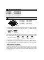
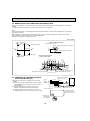
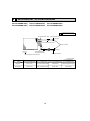
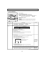
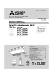
SPLIT-TYPE, HEAT PUMP AIR CONDITIONERS
November 2008
No. OCH421
REVISED EDITION-A
TECHNICAL & SERVICE MANUAL
R410A / R22
Indoor unit
[Model names]
PLFY-P12NBMU-E
PLFY-P15NBMU-E
PLFY-P18NBMU-E
PLFY-P24NBMU-E
PLFY-P30NBMU-E
PLFY-P36NBMU-E
[Service Ref.]
Revision:
• PLFY-P12/15/18/24/30/36
NBMU-ER1 are added in
REVISED EDITION-A.
• Some descriptions have
been modified.
PLFY-P12NBMU-E
PLFY-P12NBMU-ER1
PLFY-P15NBMU-E
PLFY-P15NBMU-ER1
PLFY-P18NBMU-E
PLFY-P18NBMU-ER1
PLFY-P24NBMU-E
PLFY-P24NBMU-ER1
PLFY-P30NBMU-E
PLFY-P30NBMU-ER1
PLFY-P36NBMU-E
PLFY-P36NBMU-ER1
• Plase void OCH421.
Note:
• This manual does not cover
outdoor units.
When servicing them, please
refer to the outdoor unit’s
service manual.
• RoHS compliant products
have <G> mark on the spec
name plate.
CONTENTS
Model name
indication
INDOOR UNIT
1. TECHNICAL CHANGES......................... 2
2. FEATURES............................................. 2
3. PART NAMES AND FUNCTIONS.......... 3
4. SPECIFICATIONS...................................5
5. 4-WAY AIR FLOW SYSTEM................... 9
6. OUTLINES AND DIMENSIONS............ 12
7. WIRING DIAGRAM............................... 13
8. REFRIGERANT SYSTEM DIAGRAM......14
9. MICROPROCESSOR CONTROL......... 15
10. TROUBLESHOOTING......................... 22
11. DISASSEMBLY PROCEDURE............. 31
PARTS CATALOG (OCB421)
1
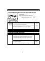
TECHNICAL CHANGES
PLFY-P12NBMU-E
PLFY-P15NBMU-E
PLFY-P18NBMU-E
PKFY-P24NBMU-E
PKFY-P30NBMU-E
PKFY-P36NBMU-E
PLFY-P12NBMU-ER1
PLFY-P15NBMU-ER1
PLFY-P18NBMU-ER1
PLFY-P24NBMU-ER1
PLFY-P30NBMU-ER1
PLFY-P36NBMU-ER1
INDOOR CONTROLLER BOARD (I.B.) has been changed.
2
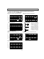
FEATURES
Models
PLFY-P12NBMU-E
PLFY-P15NBMU-E
PLFY-P18NBMU-E
PLFY-P24NBMU-E
PLFY-P30NBMU-E
PLFY-P36NBMU-E
Cooling capacity / Heating capacity
12,000 / 13,500 Btu/h
15,000 / 17,000 Btu/h
18,000 / 20,000 Btu/h
24,000 / 27,000 Btu/h
30,000 / 34,000 Btu/h
36,000 / 40,000 Btu/h
Indoor Unit
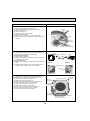
1. WIDE AIRFLOW
The new wide shape vane capable of wide angle air supply provides comfort even at the corners of a room regardless
of cooling and heating operation. A reduction in the air speed by 20% compared to the conventional product eliminates
uncomfortable draft sensation for friendly air conditioning.
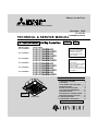
2. WAVE AIRFLOW SYSTEM (HEATING MODE)
The wave airflow system has 4 vanes where each vane runs independently. Repeating of horizontal and down blows with a
time lag allows the conditioned warm air to be distributed even to room corners thus preventing uneven room temperature
distribution.
Operation image of "Wave Airflow"
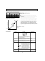
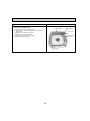
3. AUTOMATIC AIR SPEED ADJUSTMENT MODE
The automatic air speed adjustment mode is provided in addition to the 4 air speed stages of "High/Medium 1/Medium 2/
Low." Air speed can be changed freely in accordance with a difference between the set temperature and the room temperature. The automatic air speed adjustment mode presents quick cooling of a room with the high mode, such as at the starting up of cooling operation, for example. After the room temperature is stabilized, the low mode will be applied by automatic
switching to keep your comfort.
Low
Medium 2
Medium 1
High
Automatic air
speed adjustment
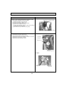
4. i-see Sensor (OPTIONAL CORNER PANEL)
The i see sensor is a radiation temperature sensor originated from Mitsubishi’s new technology. In order to create a really
comfortable space in shops and offices, it is essential to control the temperature near the floor where occupants/visitors
gather. The i see sensor measures the infrared rays generated from the surrounding wall and floor surface at an angle of
360° and the infrared ray energy is computed to convert it into the value of temperature. In addition, the floor temperature
at distant spots (radiation temperature) is also measured to supply the optimum airflow to realize comfort which was never
experienced in the past.
2
3
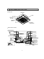
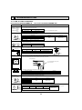
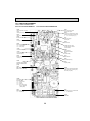
PART NAMES AND FUNCTIONS
Indoor unit
Drain pipe
Filter
Air outlet
Liquid pipe
Gas pipe
i-see sensor
(option)
Vane
Air intake
(Intake grille)
Wired remote controller
Operation Section
ON/OFF button
Temperature setting buttons
Down
Fan Speed button
Up
Timer Menu button
(Monitor/Set button)
Filter
button
(<Enter> button)
Mode button (Return button)
TEMP.
ON/OFF
Set Time buttons
Check button (Clear button)
Back
Ahead
Timer On/Off button
(Set Day button)
Test Run button
MENU
BACK
PAR-21MAA
MONITOR/SET
ON/OFF
FILTER
DAY
CLOCK
CHECK TEST
OPERATION
Airflow Up/Down button
CLEAR
Louver button
(
Operation button)
To return operation
number
Opening the
lid
Ventilation button
( Operation button)
Built-in temperature sensor
3
To go to next operation
number
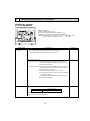
Wired remote controller
Display Section
For purposes of this explanation,
all parts of the display are shown
as lit. During actual operation, only
the relevant items will be lit.
Day-of-Week
“Sensor” indication
Shows the current day of the week.
Displayed when the remote controller
sensor is used.
Time/Timer Display
Shows the current time, unless the simple or Auto Off
timer is set.
If the simple or Auto Off timer is set, the time to be
switched off is shown.
“Locked” indicator
Indicates that remote controller buttons have been locked.
Identifies the current operation
“Clean The Filter” indicator
Shows the operating mode, etc.
*Multilanguage display is available.
To be displayed on when it is time to
clean the filter.
TIME SUN MON TUE WED THU FRI SAT
TIMER
Hr
ON
AFTER
AFTER OFF
ERROR CODE
“Centrally Controlled” indicator
Indicates that operation from the
remote controller has been prohibited by a master controller.
FUNCTION
FILTER
°F°C
°F°C
WEEKLY
SIMPLE
AUTO OFF
ONLY1Hr.
Timer indicators
The indicator comes on if the corresponding timer is set.
Fan Speed indicator
Shows the selected fan speed.
“Timer is Off” indicator
Indicates that the timer is off.
Up/Down Air Direction indicator
The indicator
shows the direction of the outcoming airflow.
“One Hour Only” indicator
Temperature Setting
Shows the target temperature.
Displayed if the airflow is set to
Low or downward during COOL
or DRY mode. (Operation varies
according to model.)
The indicator goes off in one hour,
at which time the airflow direction
also changes.
Room Temperature display
Shows the room temperature. The room
temperature display range is 46–102F.
The display blinks if the temperature
is less than 46F or 102F or more.
Ventilation indicator
Appears when the unit is running in
Ventilation mode.
Louver display
Indicates the action of the swing louver.
Does not appear if the louver is not
running.
(Power On indicator)
Indicates that the power is on.
Note:
● “PLEASE WAIT” message
This message is displayed for approximately 3 minutes when power is supplied to the indoor unit or when the unit is recovering from a power failure.
● “NOT AVAILABLE” message
This message is displayed if an invalid button is pressed (to operate a function that the indoor unit does not have).
If a single remote controller is used to operate multiple indoor units simultaneously that are different types, this message will not be displayed as
far as any of the indoor units is equipped with the function.
4
4
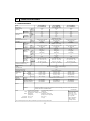
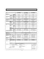
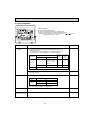
SPECIFICATIONS
4-1. SPECIFICATIONS
PLFY-P15NBMU-E
PLFY-P15NBMU-ER1
1-phase 208-230V 60Hz
15,000
4.4
0.04
0.29
PLFY-P18NBMU-E
PLFY-P18NBMU-ER1
13,500
4.0
0.02
0.14
17,000
5.0
0.03
0.22
Galvanized steel sheet
20,000
5.9
0.04
0.29
in.
mm
Ibs (kg)
10-3/16 × 33-3/32 × 33-3/32
258 × 840 × 840
49 (22)
PLP-40BAU
10-3/16 × 33-3/32 × 33-3/32
258 × 840 × 840
49 (22)
PLP-40BAU
MUNSELL (6.4Y 8.9/0.4)
10-3/16 × 33-3/32 × 33-3/32
258 × 840 × 840
51 (23)
PLP-40BAU
in.
mm
1-3/8 × 37-13/32 × 37-13/32
35 × 950 × 950
1-3/8 × 37-13/32 × 37-13/32
35 × 950 × 950
1-3/8 × 37-13/32 × 37-13/32
35 × 950 × 950
Ibs (kg)
13 (6)
13 (6)
in.WG
Pa
in.WG
Pa
Turbo fan × 1
0.000 (208V)
0
0.000 (230V)
0
494 - 530 - 565 - 636
14.0 - 15.0 - 16.0 - 18.0
233 - 250 - 267 - 300
28 - 29 - 30- 32 (208-230V)
—
—
PLFY-P12NBMU-E
PLFY-P12NBMU-ER1
Model
Power source
Cooling capacity
(Nominal)
*1
*1
Power input
Current input
*2
Heating capacity
(Nominal )
*2
Power input
Current input
External finish
External dimension H × W × D
Net weight
Decoration panel
Heat exchanger
FAN
Model
External finish
Dimension
H×W×D
Net weight
Type x Quantity
External
static press.
Motor type
Motor output
Driving mechanism
Airflow rate
(Low-Mid2Mid1-High)
Noise level (Low-Mid2-Mid1-High)
(measured in anechoic room)
BTU/h
kW
kW
A
Btu/h
kcal/h
kW
A
12,000
3.5
0.03
0.22
cfm
m3/min
L/s
388 - 424 - 459 - 494
11.0 - 12.0 - 13.0 - 14.0
183 - 200 - 217 - 233
13 (6)
Cross fin
Turbo fan × 1
0.000 (208V)
0
0.000 (230V)
0
DC motor
0.050
Direct-drive
424 - 459 - 494 - 565
12.0 - 13.0 - 14.0 - 16.0
200 - 217 - 233 - 267
dB <A>
dB <A>
dB <A>
27 - 28 - 29 - 31 (208-230V)
—
—
27 - 28 - 30 - 31 (208-230V)
—
—
kW
Insulation material
Air filter
Protection device
Refrigerant control device
Connectable outdoor unit
Liquid
Diameter of
refrigerant pipe
(O.D.)
Gas
0.050
(R410A)
in. (mm)
(R22)
(R410A)
in. (mm)
(R22)
Field drain pipe size
in. (mm)
Document
Standard
Accessory
attachment
1/4 (6.35)
1/4 (6.35)
Optional parts
PAC-SH51SP-E
PAC-SH59KF-E
PAC-SH53TM-E
Air outlet shutter plate
High efficiency filterelement
Multi-function casement
Flare
Flare
18,000
5.3
0.05
0.36
Turbo fan × 1
0.000 (208V)
0
0.000 (230V)
0
0.050
PS
PP honeycomb (long life filter, anti-bacterial type)
Fuse
LEV
R410A, R22 CITY MULTI
1/4 (6.35) Flare
1/4 (6.35) Flare
1/2 (12.7) Flare
1/2 (12.7) Flare
O.D. 1-1/4 (32)
1/2 (12.7) Flare
1/2 (12.7) Flare
O.D. 1-1/4 (32)
1/4 (6.35)
3/8 (9.52)
Flare
Flare
1/2 (12.7) Flare
5/8 (15.88) Flare
O.D. 1-1/4 (32)
Installation Manual, Instruction Book
PAC-SH51SP-E
PAC-SH59KF-E
PAC-SH53TM-E
PAC-SH51SP-E
PAC-SH59KF-E
PAC-SH53TM-E
Remark
Installation
Note:
Details on foundation work, duct work, insulation work, electrical wiring, power source switch, and other items
shall be referred to the Installation Manual.
Unit converter
*1 Nominal cooling conditions
*2 Nominal heating conditions
Indoor : 80degF D.B. / 67degF W.B.
(26.7degC D.B. / 19.4degC W.B.)
Outdoor : 95degF D.B.
(35degC D.B.)
Pipe length : 25 ft. (7.6 m)
Level difference : 0 ft. (0 m)
70degF D.B.
(21.1degC D.B.)
47degF D.B. / 43degF W.B.
(8.3degC D.B. / 6.1degC W.B.)
25 ft. (7.6 m)
0 ft. (0 m)
*Due to continuing improvement, above specification may be subject to change without notice.
5
kcal/h = kW × 860
BTU/h = kW × 3,412
cfm = m3/min × 35.31
lbs = kg/0.4536
*Above specification
data is subject to
rounding variation.
PLFY-P24NBMU-E
PLFY-P24NBMU-ER1
PLFY-P30NBMU-E
PLFY-P30NBMU-ER1
1-phase 208-230V 60Hz
30,000
8.8
0.07
0.51
PLFY-P36NBMU-E
PLFY-P36NBMU-ER1
27,000
7.9
0.05
0.36
34,000
10.0
0.06
0.43
Galvanized steel sheet
40,000
11.7
0.15
1.00
in.
mm
Ibs (kg)
10-3/16 × 33-3/32 × 33-3/32
258 × 840 × 840
51 (23)
PLP-40BAU
10-3/16 × 33-3/32 × 33-3/32
258 × 840 × 840
51 (23)
PLP-40BAU
MUNSELL (6.4Y 8.9/0.4)
11-3/4 × 33-3/32 × 33-3/32
298 × 840 × 840
60 (27)
PLP-40BAU
in.
mm
1-3/8 × 37-13/32 × 37-13/32
35 × 950 × 950
1-3/8 × 37-13/32 × 37-13/32
35 × 950 × 950
1-3/8 × 37-13/32 × 37-13/32
35 × 950 × 950
Ibs (kg)
13 (6)
13 (6)
in.WG
Pa
in.WG
Pa
Turbo fan × 1
0.000 (208V)
0
0.000 (230V)
0
777 - 883 - 989 - 1,059
22.0 - 25.0 - 28.0 - 30.0
367 - 417 - 467 - 500
35 - 38 - 41 - 43 (208-230V)
—
—
Model
Power source
Cooling capacity
(Nominal)
BTU/h
kW
kW
A
*2 Btu/h
*2 kcal/h
kW
A
*1
*1
Power input
Current input
Heating capacity
(Nominal )
Power input
Current input
External finish
External dimension H × W × D
Net weight
Decoration panel
Heat exchanger
FAN
Model
External finish
Dimension
H×W×D
Net weight
Type × Quantity
External
static press.
Motor type
Motor output
Driving mechanism
Airflow rate
(Low-Mid2Mid1-High)
Noise level (Low-Mid2-Mid1-High)
(measured in anechoic room)
cfm
m3/min
L/s
530 - 565 - 636 - 706
15.0 - 16.0 - 18.0 -20.0
250 - 267 - 300 - 333
13 (6)
Cross fin
Turbo fan × 1
0.000 (208V)
0
0.000 (230V)
0
DC motor
0.050
Direct-drive
565 - 636 - 706 - 777
16.0 - 18.0 - 20.0 - 22.0
267 - 300 - 333 - 367
dB <A>
dB <A>
dB <A>
28 - 30 - 32 - 34 (208-230V)
—
—
30 - 32 - 35 - 37 (208-230V)
—
—
kW
0.050
36,000
10.5
0.16
1.07
Turbo fan × 1
0.000 (208V)
0
0.000 (230V)
0
0.120
PS
PP honeycomb (long life filter, anti-bacterial type)
Fuse
LEV
R410A, R22 CITY MULTI
Insulation material
Air filter
Protection device
Refrigerant control device
Connectable outdoor unit
Liquid
Diameter of
refrigerant pipe
(O.D.)
Gas
(R410A)
in. (mm)
(R22)
(R410A)
in. (mm)
(R22)
Field drain pipe size
in. (mm)
Document
Standard
Accessory
attachment
Optional parts
24,000
7.0
0.06
0.43
Air outlet shutter plate
High efficiency filterelement
Multi-function casement
3/8 (9.52)
3/8 (9.52)
Flare
Flare
3/8 (9.52)
3/8 (9.52)
5/8 (15.88) Flare
5/8 (15.88) Flare
O.D. 1-1/4 (32)
Flare
Flare
5/8 (15.88) Flare
5/8 (15.88) Flare
O.D. 1-1/4 (32)
3/8 (9.52)
3/8 (9.52)
Flare
Flare
5/8 (15.88) Flare
3/4 (19.05) Flare
O.D. 1-1/4 (32)
Installation Manual, Instruction Book
PAC-SH51SP-E
PAC-SH59KF-E
PAC-SH53TM-E
PAC-SH51SP-E
PAC-SH59KF-E
PAC-SH53TM-E
PAC-SH51SP-E
PAC-SH59KF-E
PAC-SH53TM-E
Remark
Installation
Note:
Details on foundation work, duct work, insulation work, electrical wiring, power source switch, and other items
shall be referred to the Installation Manual.
Unit converter
*1 Nominal cooling conditions
*2 Nominal heating conditions
Indoor : 80degF D.B. / 67degF W.B.
(26.7degC D.B. / 19.4degC W.B.)
Outdoor : 95degF D.B.
(35degC D.B.)
Pipe length : 25 ft. (7.6 m)
Level difference : 0 ft. (0 m)
70degF D.B.
(21.1degC D.B.)
47degF D.B. / 43degF W.B.
(8.3degC D.B. / 6.1degC W.B.)
25 ft. (7.6 m)
0 ft. (0 m)
*Due to continuing improvement, above specification may be subject to change without notice.
6
kcal/h = kW × 860
BTU/h = kW × 3,412
cfm = m3/min × 35.31
lbs = kg/0.4536
*Above specification
data is subject to
rounding variation.
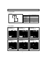
4-2. SOUND LEVEL
PLFY-P-NBMU-E
Sound level at anechoic room : Low-Mid2-Mid1-High
Sound level dB (A)
PLFY-P12NBMU-E
PLFY-P12NBMU-ER1
27-28-29-31
5 ft (1.5m)
PLFY-P15NBMU-E
PLFY-P15NBMU-ER1
PLFY-P18NBMU-E
PLFY-P18NBMU-ER1
Measurement location
27-28-30-31
28-29-30-32
PLFY-P24NBMU-E
PLFY-P24NBMU-ER1
28-30-32-34
PLFY-P30NBMU-E
PLFY-P30NBMU-ER1
30-32-35-37
PLFY-P36NBMU-E
PLFY-P36NBMU-ER1
35-38-41-43
* Measured in anechoic room.
4-3. NC CURVES
65.0
60.0
NC-60
50.0
NC-50
45.0
40.0
NC-40
35.0
30.0
NC-30
25.0
20.0
15.0
10.0
63
Approximate minimum
audible limit on
continuous noise
125
250
NC-20
500
1k
2k
4k
8k
65.0
60.0
50.0
40.0
30.0
20.0
15.0
10.0
63
NC-60
55.0
50.0
NC-50
45.0
40.0
NC-40
35.0
30.0
NC-30
25.0
10.0
63
Approximate minimum
audible limit on
continuous noise
125
250
NC-20
500
1k
2k
Approximate minimum
audible limit on
continuous noise
125
250
NC-20
500
1k
2k
4k
8k
4k
Octave band center frequencies (Hz)
60.0
50.0
40.0
8k
NC-60
55.0
50.0
NC-50
45.0
40.0
NC-40
35.0
30.0
NC-30
25.0
10.0
63
Approximate minimum
audible limit on
continuous noise
125
250
NC-20
500
1k
2k
4k
Octave band center frequencies (Hz)
7
NC-40
35.0
30.0
NC-30
25.0
20.0
15.0
10.0
63
Approximate minimum
audible limit on
continuous noise
125
250
NC-20
500
1k
2k
4k
8k
8k
Middle1 60Hz
Middle2 60Hz
High 60Hz
Low 60Hz
70.0
60.0
15.0
NC-50
45.0
PLFY-P36NBMU-E
PLFY-P36NBMU-ER1
External static pressure : 0Pa
Power source : 208,230V, 60Hz
65.0
20.0
NC-60
55.0
Octave band center frequencies (Hz)
Middle1 60Hz
Middle2 60Hz
High 60Hz
Low 60Hz
70.0
Octave band pressure level (dB) 0dB=20Pa
Octave band pressure level (dB) 0dB=20Pa
Middle1 60Hz
Middle2 60Hz
60.0
15.0
NC-30
25.0
PLFY-P30NBMU-E
PLFY-P30NBMU-ER1
External static pressure : 0Pa
Power source : 208,230V, 60Hz
65.0
20.0
NC-40
35.0
Middle1 60Hz
Middle2 60Hz
65.0
Octave band center frequencies (Hz)
PLFY-P24NBMU-E
PLFY-P24NBMU-ER1
External static pressure : 0Pa
Power source : 208,230V, 60Hz
High 60Hz
Low 60Hz
NC-50
45.0
Octave band center frequencies (Hz)
70.0
NC-60
55.0
High 60Hz
Low 60Hz
70.0
Octave band pressure level (dB) 0dB=20Pa
55.0
PLFY-P18NBMU-E
PLFY-P18NBMU-ER1
External static pressure : 0Pa
Power source : 208,230V, 60Hz
Middle1 60Hz
Middle2 60Hz
High 60Hz
Low 60Hz
70.0
Octave band pressure level (dB) 0dB=20Pa
Octave band pressure level (dB) 0dB=20Pa
Middle1 60Hz
Middle2 60Hz
High 60Hz
Low 60Hz
70.0
PLFY-P15NBMU-E
PLFY-P15NBMU-ER1
External static pressure : 0Pa
Power source : 208,230V, 60Hz
Octave band pressure level (dB) 0dB=20Pa
PLFY-P12NBMU-E
PLFY-P12NBMU-ER1
External static pressure : 0Pa
Power source : 208,230V, 60Hz
65.0
60.0
NC-60
55.0
50.0
NC-50
45.0
40.0
NC-40
35.0
30.0
NC-30
25.0
20.0
15.0
10.0
63
Approximate minimum
audible limit on
continuous noise
125
250
NC-20
500
1k
2k
4k
Octave band center frequencies (Hz)
8k
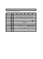
4-4. ELECTRICAL PARTS SPECIFICATIONS
Service Ref.
Parts name
Symbol PLFY-P12NBMU-E PLFY-P15NBMU-E PLFY-P18NBMU-E PLFY-P24NBMU-E PLFY-P30NBMU-E PLFY-P36NBMU-E
PLFY-P12NBMU-ER1 PLFY-P15NBMU-ER1 PLFY-P18NBMU-ER1 PLFY-P24NBMU-ER1 PLFY-P30NBMU-ER1 PLFY-P36NBMU-ER1
Room temperature
thermistor
TH21
Resistance 30"F/15.8k, 50"F/9.6k, 70"F/6.0k, 80"F/4.8k, 90"F/3.9k, 100"F/3.2k
Liquid pipe thermistor
TH22
Resistance 30"F/15.8k, 50"F/9.6k, 70"F/6.0k, 80"F/4.8k, 90"F/3.9k, 100"F/3.2k
Gas pipe thermistor
TH23
Resistance 30"F/15.8k, 50"F/9.6k, 70"F/6.0k, 80"F/4.8k, 90"F/3.9k, 100"F/3.2k
Fuse
(Indoor controller board)
FUSE
250V 6.3A
Fan motor
MF
Vane motor
MV
MSBPC20M04
DC12V 300/phase
Drain-up mechanism
DP
PLD-12230ME-1
INPUT 12/10.8W 241/Hr
Drain float swich
FS
Open/short detection
8-pole OUTPUT 50W
DC12V Stepping motor drive port dimension :3.2 (0~2000pulse)
EDM-40YGME
Linear expansion valve
LEV
Power supply terminal
block
TB2
(L1, L2, GR) 330V 30A
Transmission terminal
block
TB5
(M1, M2, S) 250V 20A
MA remote controller
terminal block
TB15
(1, 2) 250V 10A
8
8-pole OUTPUT,
120W
DC12V Stepping motor drive port
dimension :5.2 (0~2000pulse)
EDM-80YGME
5
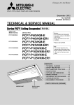
4-WAY AIR FLOW SYSTEM
5-1. PLACEMENT OF THE AIR OUTLETS
• For this grille, the blowout direction comes in 11 patterns.
Also, by setting the remote controller to the appropriate settings, you can adjust the air flow and speed. Select the settings
from Table1 according to the location in which you want to install the unit.
1) Decide on the pattern of the airflow direction.
<Table 1>
4-direction
Blowout direction
pattern
Pattern 1
3-direction
Initial setting
Pattern 4
2-direction
One air outlet
fully closed
Pattern 6
2 air outlet
fully closed
Note: For 3 and 2-direction settings, please use the air outlet shutter plate (option).
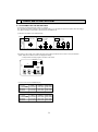
2) According to the number of air outlets and height of the ceiling to install the unit, be sure to set up the switches
(SWA, SWB) on the address board to the appropriate setting.
• Correspondence of ceiling heights to numbers of air outlets
SWA SWB
3
2
1
SW1
2
3
4
CN43
ON
OFF
CN82
1 2 3 4 5 6 7 8 9 10
SW11
9
D
7 8
7 8
E
F0 1 2
3456
2 3
2 3
4
5 6
5 6
(10ths DIGIT)
SW14
0 1
BC
0 1
4
9
SWC
789A
SW12
./
.
(BRANCH No.)
(1s DIGIT)
PLFY-P12·P15·P18·P24·P30NBMU-E(R1)
SWA
Silent
2.5m, 8.2ft
2.7m, 8.9ft
3.0m, 9.8ft
SWB
4 direction
3 direction
2 direction
Standard
2.7m, 8.9ft
3.0m, 9.8ft
3.3m, 10.8ft
High ceiling
3.5m, 11.5ft
3.5m, 11.5ft
3.5m, 11.5ft
PLFY-P36NBMU-E(R1)
SWA
SWB
4 direction
3 direction
2 direction
Silent
2.7m, 8.9ft
3.0m, 9.8ft
3.3m, 10.8ft
Standard
3.2m, 10.5ft
3.6m, 11.8ft
4.0m, 13.1ft
High ceiling
4.5m, 14.8ft
4.5m, 14.8ft
4.5m, 14.8ft
9
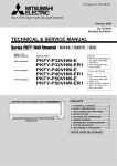
5-2. BRANCH DUCT HOLE AND FRESH AIR INTAKE HOLE
At the time of installation, use the duct holes (cut out) located at the positions shown in following diagram, as and when
required.
• A fresh air intake hole for the optional multi function casement can also be made.
Note:
The figures marked with * in the drawing below represent the dimensions of the main unit excluding those of the optional
multi function casement.
When installing the optional multi function casement, add 5-5/16” (135 mm) to the dimensions marked on the figure.
When installing the branch ducts, be sure to insulate adequately.
Otherwise, condensation and dripping may occur.
Unit : inch(mm)
Fresh air intake hole diagram
Fresh air intake hole
Branch duct hole
3-:1/8 (:2.8) burring hole
Indoor unit
6-7/32
(*158)
:4-29/32 (:125) burring hole pitch
120
120
3-:15/16 (:100) cut out hole
Ceiling
Branch duct hole diagram
(view from either side)
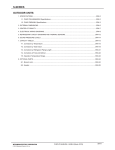
5-3. OPERATION IN CONJUNCTION WITH
DUCT FAN (Booster fan)
• Whenever the indoor unit is operating, the duct fan also
operates.
(1) Connect the optional multiple remote controller adapter
(PAC-SA88HA-E) to the connector CN51 on the indoor
controller board.
(2) Drive the relay after connecting the 12V DC relay
between the Yellow and Orange connector lines.
MB: Electromagnetic switch power relay for duct fan.
X: Auxiliary relay (For DC 12V, coil rating: 1.0W or smaller)
*6-3/32 (155)
70
:6-7/8 (:175) burring hole pitch
13-25/32 (350)
*6-9/16 (167)
3-17/32 3-15/16 3-15/16 3-17/32
(90) (100) (90) (90)
5-1/8 (130)
Refrigerant pipe
3-15/16 (100)
Drain pipe
14-:1/8 (:2.8) burring hole
:5-29/32 (:150) cut out hole
Be sure to secure insulation
material by tape, etc.
CN51
Green
5
on
Yellow
indoor
controller
Orange
1
Connector (5P)
board
Red
Brown
Indoor unit side
Multiple remote
controller adapter
PAC-SA88HA-E
Indoor controller board
CN51
Multiple remote
controller adapter
PAC-SA88HA-E
CN51
10
~
MB
Installation at site
Be sure to secure insulation
material by tape, etc.
Distance between indoor
controller board and relay
must be within 10m (33ft).
5-4. FRESH AIR INTAKE AMOUNT & STATIC PRESSURE CHARACTERISTICS
1 PLFY-P12 · P18 · P24 · P30NBMU-E(R1)
50(20)
0
-50(-20)
2 - inlet
-100(-40)
-150(-60)
1 - inlet
0
1
2
3
4
100
Taking air into the unit
6[CMM]
5
150
200
-50(-20)
2 - inlet
-100(-40)
-150(-60)
1 - inlet
-200(-80)
0
1
2
[CFM]
3
50
Air flow rate
Curve in the
graphs.
50(20)
A
0
B
Q
-50(-20)
C
A
2
E
-100(-40)
Q
-150(-60)
D
3
0
1
2
3
4
100
Air flow rate
5
6[CMM]
150
200
[CFM]
A
-200(-80)
Static pressure [Pa(in.W.G.%10-2)]
0
-50(-20)
2 - inlet
-100(-40)
-150(-60)
1 - inlet
2
50
4
100
Taking air into the unit
150
6
200
8
[CMM]
[CFM]
250
Air flow rate
0
-50(-20)
-100(-40)
-150(-60)
0
2
50
4
100
150
50(20)
0
-50(-20)
-100(-40)
2 - inlet
-150(-60)
-200(-80)
1 - inlet
0
2
50
4
100
150
Air flow rate
50(20)
-200(-80)
[CFM]
Multifunction casement + High efficiency filter
50(20)
0
200
Q
Qa
Multifunction casement + Standard filter
-200(-80)
6[CMM]
5
150
Q…Designed amount of fresh air intake
<CMM (CFM)>
A…Static pressure loss of fresh air
intake duct system with air flow
amount Q
<Pa (in.W.G.o10-2)>
…
B Forced static pressure at air conditioner inlet with air flow amount Q
<Pa (in.W.G.o10-2)>
C…Static pressure of booster fan with air
flow amount Q <Pa (in.W.G.o10-2)>
D…Static pressure loss increase amount
of fresh air intake duct system for air
flow amount Q <Pa (in.W.G.o10-2)>
…
E Static pressure of indoor unit with air
flow amount Q <Pa (in.W.G.o10-2)>
Qa … Estimated amount of fresh air
intake without D
<CMM (CFM)>
Duct characteristics
at site
0
4
100
How to read curves
2 PLFY-P36NBMU-E(R1)
Static pressure [Pa(in.W.G.%10-2)]
0
1
50
Static pressure [Pa(in.W.G.%10-2)]
50(20)
C
-200(-80)
50
Static pressure [Pa(in.W.G.%10-2)]
Multifunction casement + Standard filter
Static pressure [Pa(in.W.G.%10-2)]
Static pressure [Pa(in.W.G.%10-2)]
Multifunction casement + High efficiency filter
6
200
8
250
[CMM]
[CFM]
Air flow rate
11
6
200
8
250
[CMM]
[CFM]
6
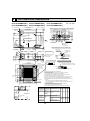
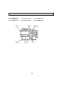
OUTLINES AND DIMENSIONS
PLFY-P15NBMU-E(R1)
PLFY-P30NBMU-E(R1)
1-31/32 to 2-3/4
(50~70)
23-1/2 (597)
Air intake hole
3-17/64
(83)
1-27/64
(36)
Corner pocket
19-11/16 (500)
Air outlet hole
37-3/8 (950)
Indoor unit
Grille
Min.94-1/2(2400)
from floor
Floor
+6-9/16(167)
70
120
(+158)
6-7/32
24-13/32 (620)
33-27/32 to 35-13/16(860~910)
Ceiling hole
+B
Cut out hole
ø3-15/16(ø100)
In case of standard grille
Vane motor
1-27/64 (36)
3-17/64
(83)
In case of wireless remote controller
Emergency operation switch <Cooling>
and Emergency Up/Down switch <Up>
Emergency operation switch <Heating>
and Emegency Up/Down switch <Down>
Receiver
Operation lamp
DEFROST/STAND BY lamp
Note:
1. Please choose the Grille from a standard grille.
2. As for drain pipe, please use VP-25 (O.D. :1-1/4(:32) PVC TUBE.)
Drain pump is included.
Max. lifting height is 70-7/18 (850mm) from the ceiling.
3. As for suspension bolt, please use M10 or W3/8. (Procured at local site)
4. Electrical box may be removed for the service purpose.
Make sure to slack the electrical wire little bit for control/power wires connection.
5. The height of the indoor unit is able to be adjusted with the grille attached.
6. For the installation of the optional high efficiency filter or optional multi-functional
casement.
1) Add 5-5/16"(135mm) to the dimensions marked on the figure.
2) The optional high efficiency filter becomes optional multi-functional casement
and concomitant use.
7. When installing the branch ducts, be sure to insulate adequately.
Otherwise condensation and dripping may occur.
(It becomes the cause of dew drops/water dew.)
8. As for necessary installation/service space, please refer to the left figure.
PLFY-P12NBMU-E Refrigerant pipe
PLFY-P15NBMU-E ···ø6.35
PLFY-P18NBMU-ER1 Flared connection
···1/4F
PLFY-P18NBMU-E Refrigerant pipe
ø6.35 / ø9.52
Flared connection
1/4F / 3/8F
(compatible)
PLFY-P24NBMU-E
PLFY-P30NBMU-E
Min.19-11/16(500)
Entire
periphery
Keep 25/64(10) to 19/32(15)
between unit ceiling
and ceiling slab.
Models
Ceiling
)
Burring hole pitch
ø4-29/32(ø125)
120
Auto vane
(Air outlet)
M
M
Burring hole
3-ø1/8(3-ø2.8)
Ceiling
23-1/2(597)
Air intake hole
37-3/8 (950)
19-11/16 (500)
Air outlet hole
M
Air intake
grille
(
Connected the attached
flexible pipe or socket.
Drain hole
Drain pump clean hole
and Drain emergency
drainage hole
M
14-ø1/8(14-ø2.8)
Burring hole
Detail drawing of fresh air intake hole
25/32
to 1-25/32
(20~45)
Ceiling
Grille
13-25/32
(350)
(ø175) 6-7/8
Burring hole pitch
ø5-29/32(ø150)
Cut out hole
1-3/8
(35)
+5-1/2
(140)
2
Suspension bolt
lower edge
Branch
duct hole
Drain pipe
connected to VP-25
(377)
14-27/32
+4-1/8(105)
1
(284)
11-3/16
(17 +50 )
11/16 +3/16
0
(60)
2-3/8
33-1/16 (840)
+35
23-13/16 -3/16
+1-3/8 (605 -5 )
Suspension bolt pitch
15/16 (24)
Suspension bolt
M10 or W3/8
6-5/16
(160)
+6-9/64
(156)
+7-15/32
(190)
A
7-3/8
(187.5)
6-5/16 (160)
D
C
3-17/32 (90)
For wiring replacement kit
terminal block
(5/16)
(7.5)
6-5/16
(160)
Indoor unit/Outdoor unit
connecting terminal block
Branch duct hole
5-29/32 (150)
33-1/16(840)
For MA-Remote controller
terminal block
+6-11/16
(170)
3-15/16(100)
3-17/32(90)
Cut out hole
3-15/16 (100)
3-17/32 (90)
(5/16)
(7.5)
6-16/5
(160)
Detail connecting of branch duct (Both aspects)
25/32 to
1-25/32
(20~45)
Fresh air
intake hole
25/32 to 1-25/32(20~45)
31-7/8(810)
Suspension bolt pitch
Unit : inch (mm)
+6-3/32(155)
Ceiling hole
33-27/32 to 35-13/16(860~910)
25/32~1-25/32(20~45)
PLFY-P18NBMU-E(R1)
PLFY-P36NBMU-E(R1)
3-15/16 (100)
5-1/8 (130)
PLFY-P12NBMU-E(R1)
PLFY-P24NBMU-E(R1)
A
B
C
D
Refrigerant pipe ···ø12.7
Flared connection ···1/2F
Refrigerant pipe ø12.7 / ø15.88
Flared connection 1/2F / 5/8F
(compatible)
9-1/2 10-3/16 3-5/32 2-29/32
(241) (258)
(80)
(74)
Refrigerant pipe ···ø15.88
Refrigerant pipe Flared connection ···5/8F
···ø9.52
PLFY-P36NBMU-E Flared connection Refrigerant pipe ø15.88 / ø19.05
···3/8F
Flared connection 5/8F / 3/4F
11-1/16 11-3/4 3-11/32 3-1/32
(compatible)
(281) (298)
(85)
(77)
Refrigerant pipe ···ø15.88
PLFY-P36NBMU-ER1
Flared connection ···5/8F
12
7
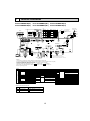
WIRING DIAGRAM
PLFY-P12NBMU-E(R1)
PLFY-P24NBMU-E(R1)
PLFY-P15NBMU-E(R1)
PLFY-P30NBMU-E(R1)
A.B
SW12
7 8
7 8
5 6
4
5 6
5
SWC
0 1
2 3
5
9
2 3
5
SW11
0 1
10ths DIGIT 1s DIGIT
5
<+1>
8
P12
(RED)
SW14 ADDRESS
F0 1 2
E
CN82
P15
BRANCH
No.
P18
1
3
Pair No.
1
8
I-SEE SENSOR MOTOR
CN6Y
(RED) 6
1
MA REMOCON
CN3A
(BLU)
1 3
I-SEE SENSOR
CN4Y
1 (WHT) 4
LEV
CN60
1 (WHT) 6
CN52
1 (GRN) 5
CN51
1 (WHT) 5
P30
ON
OFF
P36
ON
OFF
1 2 3 4 5 6
ON
OFF
ON
OFF
1 2 3 4 5 6
ON
OFF
4
ADDRESS
CN42
(RED)
SW3
SW4
SW2
1 2 3 4 5 6 7 8 910 1 2 3 4 5 1 2 3 4 5 6
CN24
(YLW)
9
1 2
LIQUID/PIPE
CN44
1 (WHT)4
CN41
1 (WHT) 4
TB2
RED
L1
BLU
L2
GRN/YLW
1 2 3 4 5 6
GR
1 3 5
ON
OFF
2 1
M-NET
CN2M
(BLU)
1
FLOAT SW
CN4F
1(WHT) 4
WHT
YLW
ORN
BLU
RED
BRN
I-SEE
SENSOR
TB15
BLU
1
BLU
6
5
M
MT
I-SEE SENSOR CORNER PANEL
(OPTION PART)
2
TO MA-REMOTE
CONTROLLER
DC8.7-13V
CNB
LED1
INTAKE
CN20
(RED)
1 2
CN27
(RED)
1 2
FAN
CNMF
(WHT)
7
4
W.B
LEV
BZ
LED2
SW1
X1
1
MS
3~
t
t
t
LED1
SW2
M
RU
TH22 TH23
FS
ZNR02 U
FUSE
ZNR01 U
CN25
3 (WHT)
1 2
CN3G
(BLK)
CND
DSA
DC311~339V
RECTIFICATION
9
4
BREAKER
(16A)
+2
1 2 3 4 5 6
OFF ON
WIRELESS
CN90
(WHT)
TO OUTDOOR UNIT
BC CONTROLLER
REMOTE CONTROLLER
DC24-30V
S
(SHIELD)
1 2 3 4 5 6
SWE
LED2
1
POWER SUPPLY
~/N 208-230V 60Hz
TB5
BLU
M1
BLU M2
MF
D.U.M 3
CNP
(BLU)
1
CNAC
(WHT)
3 1
M
1~
DP
+Be sure to turn off the source power
and then disconnect fan motor connector.
TH21
(Failure to do so will cause trouble in Fan motor)
NOTES:
1.At servicing for outdoor unit, always follow the wiring diagram of outdoor unit.
2.In case of using MA-Remote controller, please connect to TB15. (Remote controller wire is non-polar.)
3.In case of using M-NET, please connect to TB5. (Transmission line is non-polar.)
4.Symbol [S] of TB5 is the shield wire connection.
5.Symbols used in wiring diagram above are,
: terminal block,
: connecter.
6.The setting of the SW2 dip switches differs in the capacity. For the detail, refer to fig.<+1>.
+2.Use copper supply wires.
[LEGEND]
SYMBOL
I. B
CN27
CN32
CN51
CN52
DSA
FUSE
LED1
LED2
SW2
SW3
SW4
SWE
X1
ZNR01,02
NAME
INDOOR CONTROLLER BOARD
CONNECTOR DAMPER
REMOTE SWITCH
CENTRALLY CONTROL
REMOTE INDICATION
SURGE ABSORBER
FUSE (T6.3AL250V)
POWER SUPPLY (I. B)
POWER SUPPLY (I. B)
CAPACITY CODE
SWITCH
MODE SELECTION
MODEL SELECTION
DRAIN-UP MACHINE (TEST MODE)
AUX. RELAY
DRAIN WATER LIFTING-UP MACH.
VARISTOR
SYMBOL
DP
FS
LEV
MF
MV
TB2
TB5
TB15
TH21
TH22
TH23
NAME
DRAIN-UP MACHINE
DRAIN FLOAT SWITCH
LINEAR EXPANSION VALVE
FAN MOTOR
VANE MOTOR
TERMINAL
POWER SUPPLY
TRANSMISSION
BLOCK
MA-REMOTE CONTROLLER
THERMISTOR ROOM TEMP. DETECTION
(0/15k, 25/5.4k)
PIPE TEMP. DETECTION / LIQUID
(0/15k, 25/5.4k)
PIPE TEMP. DETECTION / GAS
(0/15k, 25/5.4k)
LED on indoor board for service
Mark
Meaning
LED1
Main power supply
LED2
Power supply for
MA-Remote controller
FUSE(16A)
PULL BOX
TO NEXT
INDOOR UNIT
See fig:+1
1
ADDRESS
CN81
(RED)
VANE CNV
(WHT)
P24
1 2 3 4 5 6
ON
OFF
SW2
MODELS
4
8
19 17 15 13 11 9 7 5 3 1
ON
OFF
1
CN32
(WHT) J42 J41
20 18 16 14 12 10 8 6 4 2
SW2
MODELS
3456
9
2
3
4
D
1 2 3 4 5 6 7 8 910
3
2
1
BC
SW1
4
ON
OFF
789A
GRILLE
MV MV MV MV
M M M M
(RED) 4
ADDRESS
CN43
SWA SWB
1
PLFY-P18NBMU-E(R1)
PLFY-P36NBMU-E(R1)
Function
Main Power supply (Indoor unit:208-230V)
power on
lamp is lit.
Power supply for MA-Remote controller
on
lamp is lit.
13
SYMBOL
A. B
SWA
SWB
SWC
SW1
SW11
SW12
SW14
OPTION PART
W.B
BZ
LED1
LED2
RU
SW1
SW2
NAME
ADDRESS BOARD
CEILING HEIGHT SELECTOR
SWITCH
DISCHARGE OUTLET NUMBER
SELECTOR
OPTION SELECTOR
MODE SELECTION
ADDRESS SETTING 1s DIGIT
ADDRESS SETTING 10ths DIGIT
BRANCH NO.
PCB FOR WIRELESS REMOTE CONTROLLER
BUZZER
LED (OPERATION INDICATION: GREEN)
LED (PREPARATION FOR HEATING: ORANGE)
RECEIVING UNIT
EMERGENCY OPERATION (HEAT/DOWN)
EMERGENCY OPERATION (COOL/UP)
I.B
8
REFRIGERANT SYSTEM DIAGRAM
PLFY-P12NBMU-E(R1)
PLFY-P24NBMU-E(R1)
PLFY-P15NBMU-E(R1)
PLFY-P30NBMU-E(R1)
PLFY-P18NBMU-E(R1)
PLFY-P36NBMU-E(R1)
Refrigerant flow in cooling
Refrigerant flow in heating
Gas pipe thermistor TH23
Strainer (#100mesh)
Gas pipe
Liquid pipe thermistor TH22
Flare connection
Liquid pipe
Linear expansion valve
Strainer1 (#50mesh)
Strainer2 (#100mesh)
Strainer (#100mesh)
Room temparature thermistor TH21
Heat exchanger
Unit : mm (inch)
Item
Model PLFY-P12/P15NBMU-E
PLFY-P12/P15NBMU-ER1
PLFY-P18NBMU-E
PLFY-P18NBMU-ER1
PLFY-P24/P30NBMU-E
PLFY-P24/P30NBMU-ER1
PLFY-P36NBMU-E
PLFY-P36NBMU-ER1
Gas pipe
:12.7 (1/2'')
:12.7 (1/2'')/:15.88 (5/8'')
:15.88 (5/8'')
:15.88 (5/8'')/:19.05 (3/4'')
Liquid pipe
:6.35 (1/4'')
:6.35 (1/4'')/:9.52 (3/8'')
:9.52 (3/8'')
:9.52 (3/8'')
14
9
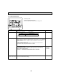
MICROPROCESSOR CONTROL
INDOOR UNIT CONTROL
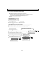
9-1. COOL OPERATION
<How to operate>
1 Press POWER ON/OFF button.
2 Press the operation MODE button to display COOL.
3 Press the TEMP. button to set the desired temperature.
NOTE: The set temperature changes 2°F when the
or
pressed one time. Cooling 67 to 87°F
TIME SUN MON TUE WED THU FRI SAT
TIMER
Hr
ON
AFTER
AFTER OFF
ERROR CODE
FUNCTION
FILTER
ûFûC
ûFûC
WEEKLY
SIMPLE
AUTO OFF
ONLY1Hr.
TEMP.
MENU
BACK
PAR-21MAA
MONITOR/SET
ON/OFF
ON/OFF
FILTER
DAY
CLOCK
Control modes
1. Thermoregulating
function
button is
CHECK TEST
OPERATION
CLEAR
Control details
1-1. Thermoregulating function (Function to prevent restarting for 3 minutes)
Remarks
desired temperature + 2°F ···Thermo ON
• Room temperature
• Room temperature desired temperature ···Thermo OFF
1-2. Anti-freezing control
Detected condition : When the liquid pipe temp. (TH22) is 32°F or less in 16
minutes from compressors start up, anti-freezing control
starts and the thermo OFF.
Released condition : The timer which prevents reactivating is set for 3 minutes,
and anti-freezing control is cancelled when any one of the
following conditions is satisfied.
Liquid pipe temp. (TH22) turns 50°F or above.
The condition of the thermo OFF has become complete
by thermoregulating, etc.
The operation modes became mode other than COOL.
The operation stopped.
2. Fan
By the remote controller setting (switch of 4 speeds+Auto)
Type
Fan speed notch
4 speeds + Auto type
[Low], [Med2], [Med1], [High], [Auto]
When [Auto] is set, fan speed is changed depending on the value of:
Room temperature - Desired temperature
To be continued on the next page.
15
From the preceding page.
Control modes
3. Drain pump
Remarks
Control details
3-1. Drain pump control
•Always drain pump ON during the COOL and DRY mode operation.
(Regardless of the thermo ON/OFF)
•When the operation mode has changed from the COOL or DRY to the others
(including Stop), OFF the control after the drain pump ON for 3 minutes.
Float switch control
• Float switch control judges whether the sensor is in the air or in the water by
turning the float switch ON/OFF.
In the water: Detected that the float switch is ON for 15 seconds.
In the air : Detected that the float switch is OFF for 15 seconds.
Float SW
ON
OFF
15sec.
In the water
(up/down vane change)
15sec. 1min.30sec.
In the air
In the water
1min.30sec.
Error
postponement
Drain pump
abnormal
(1) Initial setting: Start at COOL mode and horizontal vane.
(2) Vane position:
Horizontal →Downward A →Downward B →Downward C→Downward D→Swing→Auto
→
4. Vane
15sec.
(3) Restriction of the downward vane setting
When setting the downward vane A, B, C or D in [Med1], [Med2] or [Low] of the
fan speed notch, the vane changes to horizontal position after 1 hour have passed.
16
· "ONLY 1 Hr"
appears on the
wired remote
controller.
9-2. DRY OPERATION
TIME SUN MON TUE WED THU FRI SAT
TIMER
Hr
ON
AFTER
AFTER OFF
ERROR CODE
FUNCTION
FILTER
ûFûC
ûFûC
WEEKLY
SIMPLE
AUTO OFF
ONLY1Hr.
TEMP.
MENU
BACK
PAR-21MAA
MONITOR/SET
ON/OFF
ON/OFF
CHECK TEST
OPERATION
CLEAR
Control modes
Remarks
Control details
1. Thermo regulating 1-1. Thermo regulating function (Function to prevent restarting for 3 minutes)
Setting the Dry thermo by the thermo regulating signal and the room
function
temperature (TH21).
Dry thermo ON Room temperature desired temperature + 2°F
Dry thermo OFF Room temperature desired temperature
Dry thermo Dry thermo
3 min. passed since starting operation
Room
ON
OFF
temperature Thermo regulating signal
Room temperature (T1) time (min) time (min)
ON
Over 64F
OFF
T1 83°F
9
3
83°F > T1 79°F
7
3
79°F > T1 75°F
5
75°F > T1
3
3
3
3
10
Unconditional
Dry thermo OFF
Less than 64F
1-2. Frozen prevention control
No control function
2. Fan
Indoor fan operation controlled depends on the compressor conditions.
Dry thermo
Fan speed notch
ON
[Low]
OFF
Excluding the following
Stop
Room temp. < 64°F
[Low]
Note: Remote controller setting is not acceptable.
3. Drain pump
button is
FILTER
DAY
CLOCK
<How to operate>
1 Press POWER ON/OFF button.
2 Press the operation MODE button to display DRY.
3 Press the TEMP. button to set the desired temperature.
NOTE: The set temperature changes 2°F when the
or
pressed one time. Dry 67 to 87°F
Same control as COOL operation
Same control as COOL operation
4. Vane
(up/down vane change)
17
9-3. FAN OPERATION
<How to operate>
1 Press POWER ON/OFF button.
2 Press the operation MODE button to display FAN.
TIME SUN MON TUE WED THU FRI SAT
TIMER
Hr
ON
AFTER
AFTER OFF
ERROR CODE
ûFûC
ûFûC
WEEKLY
SIMPLE
AUTO OFF
ONLY1Hr.
TEMP.
MENU
BACK
PAR-21MAA
MONITOR/SET
FUNCTION
FILTER
ON/OFF
ON/OFF
FILTER
DAY
CLOCK
CHECK TEST
OPERATION
CLEAR
Control modes
1. Fan
Control details
Remarks
Set by remote controller.
Type
Fan speed notch
4 speeds + Auto type
[Low], [Med2], [Med1], [High], [Auto]
When [Auto] is set, fan speed becomes [Low].
2. Drain pump
2-1. Drain pump control
The drain pump turns ON for the specified amount of time when any of the following
conditions is met:
ON for 3 minutes after the operation mode is switched from COOL or DRY to
another operation mode (FAN).
ON for 6 minutes after the float switch is submerged in the water when the
float swich control judges the sensor is in the water.
2-2. Float switch control
• Float switch control judges whether the sensor is in the air or in the water by
turning the float switch ON/OFF.
In the water : Detected that the float switch is ON for 15 seconds.
In the air
: Detected that the float switch is OFF for 15 seconds.
3. Vane
Same as the control performed during the COOL operation, but with no restriction
(up/down vane change) on the vane's downward blow setting
18
· Same control
as COOL
operation
9-4. HEAT OPERATION
<How to operate>
1 Press POWER ON/OFF button.
2 Press the operation MODE button to display HEAT.
3 Press the TEMP. button to set the desired temperature.
NOTE: The set temperature changes 2°F when the
or
pressed one time. Heating 63 to 83°F.
TIME SUN MON TUE WED THU FRI SAT
TIMER
Hr
ON
AFTER
AFTER OFF
ERROR CODE
ûFûC
ûFûC
WEEKLY
SIMPLE
AUTO OFF
ONLY1Hr.
TEMP.
MENU
BACK
PAR-21MAA
MONITOR/SET
FUNCTION
FILTER
ON/OFF
ON/OFF
<Display in HEAT operation>
[DEFROST]
The [DEFROST] symbol is only displayed during the defrost operation.
[STANDBY]
The [STANDBY] symbol is only displayed during the hot adjust mode.
FILTER
DAY
CLOCK
CHECK TEST
OPERATION
CLEAR
Control modes
1. Thermoregulating
function
2. Fan
button is
Remarks
Control details
1-1. Thermoregulating function (Function to prevent restarting for 3 minutes)
• Room temperature desired temperature -2°F ···Thermo ON
• Room temperature desired temperature
···Thermo OFF
By the remote controller setting (switch of 4 speeds+Auto)
Type
Fan speed notch
4 speeds + Auto type
[Low], [Med2], [Med1], [High], [Auto]
When [Auto] is set, fan speed is changed depending on the value of:
Desired temperature - Room temperature
Give priority to under-mentioned controlled mode
2-1. Hot adjust mode
2-2. Preheating exclusion mode
2-3. Thermo OFF mode (When the compressor off by the thermoregulating)
2-4. Cool air prevention mode (Defrosting mode)
2-1. Hot adjust mode
The fan controller becomes the hot adjuster mode for the following conditions.
When starting the HEAT operation
When the thermoregulating function changes from OFF to ON.
When release the HEAT defrosting operation
Hot adjust mode *1
*1 "STAND BY"
will be displayed
during the hot
adjust mode.
Set fan speed by the remote controller
[Low]
[Extra Low]
A
B
C
A: Hot adjust mode starts.
B: 5 minutes have passed since the condition A or the indoor liquid pipe
temperature turned 95°F or more.
C: 2 minutes have passed since the condition A. (Terminating the hot adjust mode)
2-2. Preheating exclusion mode
When the condition changes the auxiliary heater ON to OFF (thermoregulating or
operation stop, etc), the indoor fan operates in [Low] mode for 1 minute.
· This control is
same for the
model without
auxiliary heater.
To be continued on the next page.
19
From the preceding page
Control details
Control modes
2. Fan
Remarks
2-3. Thermo OFF mode
When the thermoregulating function changes to OFF, the indoor fan operates in
[Extra low].
2-4. Heat defrosting mode
The indoor fan stops.
3. Drain pump
3-1. Drain pump control
The drain pump turns ON for the specified amount of time when any of the following
conditions is met:
ON for 3 minutes after the operation mode is switched from COOL or DRY to
another operation mode (FAN).
ON for 6 minutes after the float switch is submerged in the water when the
float swich control judges the sensor is in the water.
3-2. Float switch control
• Float switch control judges whether the sensor is in the air or in the water by
turning the float switch ON/OFF.
In the water: Detected that the float switch is ON for 15 seconds.
In the air : Detected that the float switch is OFF for 15 seconds.
(1) Initial setting: OFF → HEAT···[last setting]
When the last setting is [Swing] ··· [Downward D]
When changing the mode from exception of HEAT to HEAT operation
···[Downward D]
(2) Vane position:
Horizontal →Downward A →Downward B →Downward C→Downward D→Swing→Auto
→
4. Vane control
(Up/down vane
change)
(3) Restriction of vane position
The vane is horizontally fixed for the following modes.
(The control by the remote controller is temporally invalidated and control by
the unit.)
•Thermo OFF
•Hot adjust [Extra low] mode
•Heat defrost mode
20
· Same control as
COOL operation
9-5. AUTO OPERATION [AUTOMATIC COOL/HEAT CHANGE OVER OPERATION]
TIME SUN MON TUE WED THU FRI SAT
TIMER
Hr
ON
AFTER
AFTER OFF
ERROR CODE
ûFûC
ûFûC
TEMP.
MENU
BACK
PAR-21MAA
MONITOR/SET
FUNCTION
FILTER
WEEKLY
SIMPLE
AUTO OFF
ONLY1Hr.
ON/OFF
ON/OFF
button is
FILTER
DAY
CLOCK
<How to operate>
1 Press POWER ON/OFF button.
2 Press the operation MODE button to display AUTO.
3 Press the TEMP. button to set the desired temperature.
NOTE: The set temperature changes 2°F when the
or
pressed one time. Automatic 67 to 83°F
CHECK TEST
OPERATION
CLEAR
Control details
Control modes
Remarks
1. Initial value of HEAT mode for room temperature < Desired temperature
operation mode COOL mode for room temperature Desired temperature
2. Mode change (1) HEAT mode → COOL mode
Room temperature Desired temperature + 3°F. or 3 min. has passed
(2) COOL mode → HEAT mode
Room temperature Desired temperature - 3°F. or 3 min. has passed
3. COOL mode
Same control as cool operation
4. HEAT mode
Same control as heat operation
9-6. WHEN UNIT IS STOPPED CONTROL MODE
Control modes
1. Drain pump
Control details
Remarks
1-1. Drain pump control
The drain pump turns ON for the specified amount of time when any of the following
conditions is met:
ON for 3 minutes after the operation mode is switched from COOL or DRY to
another operation mode (FAN).
ON for 6 minutes after the float switch is submerged in the water when the
float swich control judges the sensor is in the water.
1-2. Float switch control
• Float switch control judges whether the sensor is in the air or in the water by
turning the float switch ON/OFF.
In the water : Detected that the float switch is ON for 15 seconds.
In the air
: Detected that the float switch is OFF for 15 seconds.
21
· Same control
as COOL
operation
10
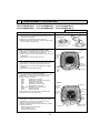
TROUBLESHOOTING
10-1. HOW TO CHECK THE PARTS
PLFY-P12/15/18/24/30/36NBMU-E
PLFY-P12/15/18/24/30/36NBMU-ER1
Parts name
Check points
Room temperature
thermistor
(TH21)
Liquid pipe thermistor
(TH22)
Gas pipe thermistor
(TH23)
Disconnect the connector then measure the resistance using a tester.
(At the ambient temperature 50"F~86"F)
Vane motor (MV)
Measure the resistance between the terminals using a tester.
(At the ambient temperature of 68°F~86°F)
Normal
Abnormal
4.3k~9.6k
Open or short
White
Orange
Red
Yellow
Blue
Drain pump (DP)
YLW
Connector
(-, -, -, -)
(-
, -, -, -)
(-, -, -, -)
(-, -, -
, -)
Normal
Abnormal
300
Open or short
Measure the resistance between the terminals using a tester.
(Winding temperature 68°F)
1
3
YLW
Red - Yellow
Red - Blue
Red - Orange
Red - White
(Refer to the next page for a detail.)
Drain float switch (FS)
Normal
290
Abnormal
Open or short
Measure the resistance between the terminals using a tester.
Moving part
1
State of moving part
Normal
Abnormal
2
UP
Short
Other than short
3
DOWN
Open
Other than open
Switch
Magnet
4
i-see sensor
(Option)
Moving
Part
Turn on the indoor unit with the black plastic tape on the outside of i-see sensor controller board.
With electricity being turned on, measure the power voltage between connectors with tester.
i-see sensor rotates then pull out the connector of motor for i-see sensor.
Black plastic tape
Do not disassemble corner panel
with i-see sensor.
4
3
2 1
i-see sensor (At the ambient temperature of 50°F~104°F)
4 3
2
i-see sensor connector
1
Blue BlackPink Brown
(–)—(+)
Normal
DC 1.857V~ 3.132V
Abnormal
Other than the normal
(+)—(–)
DC 0.939V~ 1.506V
Other than the normal
NOTE : Be careful of handing such a static electricity.
Vane motor for
i-see sensor (Option)
White
Orange
Red
Blue
Linear expansion
valve (LEV)
Yellow
Blue
Yellow
White
Red
Connector
Red - Yellow
Red - Blue
Red - Orange
Red - White
Normal
Abnormal
250
Open or short
Disconnect the connector then measure the resistance valve using a tester.
Normal
Brown
M
Measure the resistance between the terminals using a tester.
(At the ambient temperature of 68°F~86°F)
White-Red
Yellow-Brown
Abnormal
Orange-Red
150k $10%
Orange
22
Blue-Brown
Open or short
Refer to 8-1-2.
10-1-1. Thermistor
<Thermistor characteristic graph>
< Thermistor for lower temperature >
50
Room temperature thermistor (TH21)
Liquid pipe temperature thermistor (TH22)
Gas pipe temperature thermistor (TH23)
Thermistor R0=15k' ± 3%
Fixed number of B=3480 ± 2%
Rt=15exp { 3480(
30_F
50_F
70_F
80_F
90_F
100_F
10-1-2.
1
273+(t-32)/1.8
40
Resistance (k)
Thermistor for
lower temperature
1 )}
273
30
20
15.8k'
9.6k'
6.0k'
4.8k'
3.9k'
3.2k'
10
0
-20
0
20
40
60
80
Temperature (°F)
100
120
Linear expansion valve
1 Operation summary of the linear expansion valve
• Linear expansion valve open/close through stepping motor after receiving the pulse signal from the indoor controller board.
• Valve position can be changed in proportion to the number of pulse signals.
<Connection between the indoor controller board and the linear expansion valve>
Controller board
DC12V
Brown
6
Red
5
Brown
:4
Blue
4
:4
Yellow
:3
Orange
3
:3
:2
Yellow
2
:2
:1
White
1
:1
Linear expansion valve
4
M
6
5
2
1
White Red
3
Orange
Blue
Drive circuit
Connector(CN60)
Note : Since the number of the connector at the controller board side and the relay connector are different, follow the color of
the lead wire.
23
<Output pulse signal and the valve operation>
Output
Output
(Phase)
1
ON
ON
OFF
OFF
{1
{2
{3
{4
2
OFF
ON
ON
OFF
3
OFF
OFF
ON
ON
4
ON
OFF
OFF
ON
2 Linear expansion valve operation
C
Valve position (capacity)
D
• When the valve moves smoothly, there is no sound or vibration
occurring from the linear expansion valves, however, when the
pulse number moves from E to A or when the valve is locked,
more sound can be heard than in a normal situation.
• Sound can be detected by placing the ear against the screw driver
handle while putting the screw driver tip to the linear expansion
valve.
Close
Open
A
E
B
Note:
• When linear expansion valve operation stops, all output phase
become OFF.
• At phase interruption or when phase does not shift in order, motor
does not rotate smoothly and motor will lock and vibrate.
• When the switch is turned on, 2200 pulse closing valve signal will
be sent till it goes to point A in order to define the valve position.
Open
Close
Closing a valve : 1 → 2 → 3 → 4 → 1
Opening a valve : 4 → 3 → 2 → 1 → 4
The output pulse shifts in above order.
Outdoor unit R410A model : 1400 pulse
Outdoor unit R22 model
: 2000 pulse
Opening a valve
all the way
Pulse number
Extra tightening (200~800 pulse)
3 Trouble shooting
Symptom
Check points
Countermeasures
Operation circuit
failure of the micro
processor
Disconnect the connector on the controller board, then con- Exchange the indoor connect LED for checking.
troller board at drive circuit
6
5
failure.
4
3
2
1
1k LED
When power is turned on, pulse signals will output for 10
seconds. There must be some defects in the operation circuit
if the LED does not light while the signals are output or keeps
lighting even after the signals stop.
Linear expansion
valve mechanism is
locked.
Motor will idle and make a ticking noise when the motor is
Exchange the linear expanoperated while the linear expansion valve is locked. This tick- sion vale.
ing sound is the sign of the abnormality.
Short or breakage
Measure the resistance between each coil (white-red, yellow- Exchange the linear expanof the motor coil of
brown, orange-red, blue-brown) using a tester. It is normal if sion valve.
the linear expansion the resistance is in the range of 150' ±10%.
valve
Valve does not close To check the linear expansion valve, operate the indoor unit If large amount of refrigercompletely.
in fan mode and at the same time operate other indoor units ant is leaked, exchange
the linear expansion valve.
in cooling mode, then check the pipe temperature <liquid
pipe temperature> of the indoor unit by the
outdoor multi controller board operation
monitor. During fan operation, linear expansion valve is closed completely and if there
Thermistor
(Liquid pipe) is any leaking, detecting temperature of
the thermistor will go lower. If the detected
Linear
temperature is much lower than the temexpansion
valve
perature indicated in the remote controller,
it means the valve is not closed all the way.
It is not necessary to exchange the linear expansion valve, if
the leakage is small and not affecting normal operation.
Wrong connection
of the connector or
contact failure
Check the color of lead wire and missing terminal of the con- Disconnect the connector
nector.
at the controller board,
then check the continuity.
24
10-1-3. DC Fan motor (fan motor/indoor controller board)
Check method of indoor fan motor (fan motor/indoor controller board)
Notes
· High voltage is applied to the connecter (CNMF) for the fan motor. Pay attention to the service.
· Do not pull out the connector (CNMF) for the motor with the power supply on.
(It causes trouble of the indoor controller board and fan motor)
Self check
Conditions : The indoor fan cannot turn around.
Wiring contact check
Contact of fan motor connector (CNMF)
Contact of power supply cable
Is there contact failure ?
Yes
Wiring recovery
No
Power supply check (Remove the connector (CNMF))
Measure the voltage in the indoor controller circuit board.
TEST POINT : VDC (between 1 (+) and 4 (-) of the fan connector): VDC DC294~325V
TEST POINT : VCC (between 5 (+) and 4 (-) of the fan connector): VCC DC15V
Is the voltage normal?
Trouble of the indoor controller board
Replace the indoor controller board.
No
Yes
Yes
Fan motor position sensor signal check
Turn around the fan motor more than one revolution slowly, and check
the voltage TEST POINT VFG (between 7(+) and 4(-)).
No
Does the voltage repeat DC0V and DC15V?
Yes
Replace the fan motor.
Trouble of the fan motor
Replace the fan motor.
Check the operation of fan.
OK
Check the operation of fan.
NG
Yes
Replace the indoor controller board.
NG
END
Replace the indoor
controller board
NG
Replace the fan motor.
25
OK
Check the operation of fan.
OK
END
END
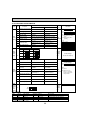
10-2. FUNCTION OF DIP SWITCH
Switch Pole
SW1
Function
setting
ON
OFF
1
Thermistor <Room temperature
detection> position
Built-in remote controller
Indoor unit
2
Filter clogging detection
Provided
Not provided
3
Filter cleaning
2,500hr
100hr
4
Fresh air intake
Effective
Not effective
5
Switching remote
display
Indicating fan operation
Thermo ON signal display ON/OFF
6
Humidifier control
7
Low +3
Extra low +3
8
Air flow set in case of
Heat thermo OFF
Setting air flow +3
Depends on SW1-7
9
Auto restart function
Effective
Not effective
Power ON/OFF by breaker
Effective
Not effective
10
SW2
MODELS
SW2
Capacity
code
setting 1~6
P12
P15
P18
SW3
Function
setting
Operation by switch
Function
ON
OFF
ON
OFF
ON
OFF
Remarks
Address board
<Initial setting>
ON
OFF
Note :
1 2 3 4 5 6 7 8 9 10
+1 Fan operation at Heating
mode
+2 Heating thermo ON is
Under
operating.
Always operated while the heat in ON +1 Operated depends on the condition +2 suspension
P24
1 2 3 4 5 6
P30
1 2 3 4 5 6
P36
1 2 3 4 5 6
+3
SW1-7
OFF
ON
OFF
ON
ON
OFF
ON
OFF
ON
OFF
Before
power
supply
ON
1 2 3 4 5 6
1 2 3 4 5 6
Extra low
Low
Setting air flow
Stop
<Initial setting>
Set for each capacity.
1 2 3 4 5 6
Heat pump/Cooling only
Cooling only
Heat pump
2
Louver/Humidifier
Available
Not available
3
Vane
Available
Not available
4
Vane swing function in heating
Available
(wave-flow)
Not available
5
Vane horizontal angle Second setting +4
First setting +4
6
Vane horizontal angle Third setting +4
Depends on SW3-5
7
Changing the opening of
linear expansion valve
Effective
Not effective
8
Sensible temperatre correction Not effective
9
Superheat setting temperature +5
—
—
10
Sub cool setting temperature +5
—
—
Indoor controller board
<Initial setting>
ON
OFF
1 2 3 4 5 6 7 8 9 10
Note :
+4 SW3-5,6
Under
+5 Please do not use
suspension
SW-3-9,10 as trouble
might be caused by the
usage condition.
Effective
Before
power
supply
ON
ON
OFF
1 2 3 4 5
Indoor controller board
Note : +4 SW3-5,6
SW3-5
SW3-6
Vane setting
OFF
OFF
Set up ON
OFF
Set up OFF
ON
Set up ON
ON
unused
* Be careful of the smudge on ceiling.
SW1-8
OFF
OFF
ON
ON
Indoor controller board
SW2
MODELS
1
SW4
Model
Selection
(Setting 1~5
for
PLFY
series)
Effective
timing
Initial setting Setting
Standard
Less draft *
Less smudging
—
●
26
Vane position
Standard
Upward position than the standard
Downward position than the standard
—
Effective
timing
Operation by switch
Switch Pole
(High ceiling)
SWA
Ceiling
1~3 (Standard)
height
selector
(Silent)
3
2
1
PLFY-P12·P15·P18·P24·P30NBMU-E(R1)
SWA
SWB
4 direction
3 direction
2 direction
SWB
(2 direction) 2
Address board
* Ceiling height can be changed depending on
SWB setting.
Silent
2.5m, 8.2ft
2.7m, 8.9ft
3.0m, 9.8ft
PLFY-P36NBMU-E(R1)
SWA
SWB
Discharge
3
outlet
number
selector
Remarks
4 direction
3 direction
2 direction
Silent
2.7m, 8.9ft
3.0m, 9.8ft
3.3m, 10.8ft
<Initial setting>
3
2
1
Standard
2.7m, 8.9ft
3.0m, 9.8ft
3.3m, 10.8ft
High ceiling
3.5m, 11.5ft
3.5m, 11.5ft
3.5m, 11.5ft
Standard
3.2m, 10.5ft
3.6m, 11.8ft
4.0m, 13.1ft
High ceiling
4.5m, 14.8ft
4.5m, 14.8ft
4.5m, 14.8ft
Address board
(3 direction) 3
(4 direction) 4
<Initial setting>
Under
operation
or
suspension
2
3
4
Address board
(Standard)
When attaching the optional high performance
filter elements (multi function casement) to
the unit, be sure to attach it to the option
side in order to prevent the airflow reducing.
<Initial setting>
78
78
Before
power
supply
ON
Address board
<Initial setting>
SW14
F01
45 6
27
78
78
90 1
23
How to set branch number SW14 (Series R2 only)
Match the indoor unit’s refrigerant pipe with the BC
contoller’s end connection number
Remain other than series R2 at "0".
SW11
90 1
CDE
AB
CDE
AB
F01
45 6
789
Rotary switch
45 6
SW14
SW12
23
1
<Initial setting>
23
10
How to set address
Example : If address is "3", remain SW12
(for over 10) at "0", and match SW11 (for 1 to 9)
with "3".
789
90 1
45 6
SW11
90 1
45 6
SW12
23
Rotary switch
Address board
23
SW14
Branch
No.
setting
(Option)
23
SW11
1s digit
address
setting
SW12
10ths digit
address
setting
2
45 6
SWC
Option
selector
J41, J42
Wireless
remote
controller
Pair No.
Jumper
Switch Pole
Effective
timing
Operation by switch
• To operate each indoor unit by each remote controller when installed 2 indoor
units or more are near, Pair No. setting is necessary.
Pair No. setting is available with the 4 patterns (Setting patters A to D).
Make setting for J41, J42 of indoor controller board and the Pair No. of
wireless remote controller.
• You may not set it when operating it by one remote controller.
Setting for indoor unit
Jumper wire J41, J42 on the indoor controller board are cut according to
the table below.
Wireless remote controller Pair No.:
Setting operation
1. Press the SET button (using a pointed implement). Check that the
remote controller's display has stopped before continuing.
MODEL SELECT blinks, and the model No. (3 digits) appears (steadily-lit).
2. Press the MINUTE button twice. The pair number appears flashing.
3. Press the temperature
buttons to select the pair number to set.
4. Press the SET button (using a pointed implement). The set Pair No. is
displayed (steadily-lit) for 3 seconds, then disappears.
Remarks
Indoor controller board
<Initial setting>
Pattern A
Pair No.
Under
operation
or
suspension
MODEL SELECT
Setting pattern
Indoor controller
Jumper wire
Connector
OFF
OFF
h
min
SET
RESET
Minute
button
CLOCK
Indoor controller board
<Initial setting>
SWE
ON
AUTO START
SET button
Drain pump and fan are activated simultaneously after the connector
SWE is set to ON and turn ON the power.
SWE
AUTO STOP
TEST RUN
J41
J42
A
—
—
0
Initial setting
B
Cut
—
1
—
C
—
Cut
2
—
D
Cut
Cut
3
—
+Pair No.4-9 of wireless remote controller is setting pattern D.
SWE
Test run
for
Drain
pump
FAN
VANE
CHECK LOUVER
Pair No. of wireless
remote controller +
Temperature
button
TEMP
ON/OFF
MODE
Model No.
Under
operation
SWE
ON
The connector SWE is set to OFF after test run.
OFF
28
ON
10-3. TEST POINT DIAGRAM
10-3-1. Indoor controller board
PLFY-P12/15/18/24/30/36NBMU-E
PLFY-P12/15/18/24/30/36NBMU-ER1
CN60
CN6Y
Linear expansion valve (LEV)
output
12VDC pulse output
i-see sensor motor output
12VDC pulse output
CN3A
CN4Y
Connect to the terminal block (TB15)
(MA-Remote controller connecting wire)
1 - 3 : 8.7-13V DC (Pin1 (+))
i-See sensor
CN52
Remote indicator
CNV
CN51
Vane motor output
12VDC pulse
Centrally controlled
CN32
Remote switch
CN44
Pipe temperature thermistor
1-2 : Liquid (TH22)
3-4 : Gas (TH23)
Jumper wire J41, J42
Pair No.setting for wireless
remote controller
CN4F
LED2
Drain float switch (FS)
Power supply for
MA-Remote controller
CN20
Room temperature
thermistor (TH21)
SW3
Function setting
CN27
SW4
Damper signal output
12VDC(1 : +)
Model selection
SWE
Test run(Drain pump)
CN90
Connect to the wireless
remote controller board
(W.B)
SW2
Capacity setting
LED1
Main power supply
(Indoor unit : 208-230V)
CN2M
Connect to the terminal block (TB5)
(M-NET transmission connecting wire)
24-30VDC (non-polar)
CNMF
Connect to the
fan motor (MF)
1-4
5-4
6-4
7-4
:
:
:
:
DC310~340V
DC15V
DC0~6V
DC0 or DC15V (Stop)
DC7.5V (Operation)
(12VDC pulse)
CND
CNP
Drain pump output (DP)
Power supply for indoor controller board
3 - 5 : 208-230VAC
1-3 : 208-230VAC
FUSE
6.3A 250V
29
10-3-2. Circuit board
PLFY-P12NBMU-E(R1)
PLFY-P24NBMU-E(R1)
PLFY-P15NBMU-E(R1)
PLFY-P30NBMU-E(R1)
PLFY-P18NBMU-E(R1)
PLFY-P36NBMU-E(R1)
SW1
SWA
SWB
Function setting
Ceiling height
selector
Discharge outlet
number selector
SW12
SW11
SWC
Address setting
2nd digit
Address setting
1st digit
Option selector
30
11
DISASSEMBLY PROCEDURE
PLFY-P12NBMU-E(R1)
PLFY-P24NBMU-E(R1)
PLFY-P15NBMU-E(R1)
PLFY-P30NBMU-E(R1)
PLFY-P18NBMU-E(R1)
PLFY-P36NBMU-E(R1)
Be careful when removing heavy parts.
OPERATING PROCEDURE
PHOTOS & ILLUSTRATIONS
1. Removing the air intake grille
(1) Slide the knob of air intake grille toward the arrow 1 to
open the air intake grille.
(2) Remove drop prevention hook from the panel.
(3) Slide the shaft in the hinge to the direction of the arrow 2
and remove the air intake grille.
Figure 1
2. Removing the room temperature thermistor (TH21)
(1) Remove the air intake grille and the filter. (See Figure 1)
(2) Remove the 2 screws from the electrical box.
(3) Disconnect the connector CN20 (Red) from the indoor controller board.
(4) Remove the room temperature thermistor.
Photo 1
3. Removing the address board (A.B)
(1) Remove the air intake grille and the filter. (See Figure 1)
(2) Remove the 2 screws from the address board cover.
(3) Disconnect the connectors CN43 (RED/4P) and CN82
(RED/8P).
(4) Slide and remove the address board.
4. Removing the indoor controller board (I.B)
(1) Remove the air intake grille and the filter. (See Figure 1)
(2) Remove the 2 screws from the electrical box cover.
(3) Disconnect the connectors :
CNMF
(White/7P) for fan motor
CN44
(White/4P) for thermistor (TH22/TH23)
CNP
(Blue/3P) for drain pump
CN4F
(White/4P) for float switch
CN01
(Black/5P) for earth and TB2
CNV
(White/20P) for vane motor
CN81, CN42 (Red/8P, 4P) for address board
CN2M
(Blue/2P) for TB5
CN3A
(Blue/3P) for TB15
(4) Remove the 6 supports from indoor controller board.
(5) Remove the indoor controller board.
5. Removing the electrical box
(1) Remove the air intake grille and the filter. (See Figure 1)
(2) Remove the 2 screws from the electrical box cover.
(3) Disconnect the connectors. (Refer to 4.)
(4) Remove 4 electrical box fixing screws and remove 2 hooks.
(5) Pull the electrical box.
<Electrical parts in the electrical box>
Indoor controller board
Terminal block (TB2) (TB5)
31
Filter
Address board
cover fixing
screw
MA remote
controller
terminal
cover
Address
board
Address
board cover
fixing screw
Terminal
cover
fixing
screw
Electrical box cover
fixing screws
Electrical box cover
Photo 2
Bell mouth
Room temp.
thermistor
(TH22)
Turbo fan
Electrical
box fixing
screw
Nut
Electrical
box
fixing
screw
Electrical box
Indoor controller
board
Support for Indoor
controller board
OPERATING PROCEDURE
PHOTOS & ILLUSTRATIONS
Photo 3
6. Removing the fan and fan motor (MF)
(1) Remove the electrical box. (See Photo 2)
(2) Remove the bell mouth (3 screws). (See Photo 2)
(3) Remove the turbo fan nut.
(4) Pull out the turbo fan.
(5) Remove the wire cover (3 screws).
(6) Remove 2 wiring clamps.
(7) Disconnect the connector of the fan motor (CNMF).
(8) Remove the 3 nuts and washers and rubber mounts of the
fan motor.
Coil plate
Fan motor
Clamp
Wire cover
fixing screw
Nut
Washer
Rubber mount
Figure 2
7. Removing the panel
(1) Remove the air intake grille and the filter. (See Figure 1)
(2) Disconnect the connector CNV (White/20P).
Corner panel (See Figure 2)
(3) Remove the corner screw.
(4) Slide the corner panel to the direction of the arrow 1, and
remove the corner panel.
Panel (See Photo 4, 5)
(5) Remove the 2 screws from the panel which fixes to the oval
holes.
(6) Rotate the panel a little to come to the bell shaped hole
where the screw is large and remove the panel.
Screw
Detail Screw Corner panel
Panel
Corner panel
Photo 4
Photo 5
Bell shaped hole
Oval hole
8. Removing the drain pan
(1) Remove the air intake grille and the filter. (See Figure 1)
(2) Remove the 2 screws from the electrical box cover.
(3) Disconnect the connectors. (Refer to 4.)
(4) Remove the panel. (See Photo 4, 5)
(5) Remove the electrical wiring service panel (3 screws).
(6) Remove the drain pump wire cover (1 screw).
(7) Remove the electrical box. (See Photo 2)
(8) Remove the bell mouth. (See Photo 2)
(9) Remove the 4 screws and pull out the drain pan.
w Pull out the left and right of the pan gradually.
Be careful not to crack or damage the pan.
Photo 6
Drain pump wire cover
Drain pan
fixing screw
Drain pan
fixing screw
Electrical wiring
service panel
Drain pan
fixing screw
Drain pan
Electrical wiring service panel fixing screw
32
OPERATING PROCEDURE
PHOTOS & ILLUSTRATIONS
9. Removing the liquid pipe temperature thermistor (TH22)
and gas pipe temperature thermistor (TH23)
(1) Remove the drain pan. (See Photo 6)
(2) Remove the turbo fan. (Refer to 6)
(3) Remove the 2 wiring clamps. (See Photo 3)
(4) Remove the coil plate (2 screws).
(5) Remove the thermistors which are inserted into the holders
installed to the thin copper pipe.
(6) Disconnect the 4-pin white connector (CN44).
Photo 7
Gas pipe temp. thermistor (TH23)
Liquid pipe temp. thermistor (TH22)
10 Removing the drain pump (DP) and float switch (FS)
(1) Remove the drain pan. (See Photo 6)
(2) Cut the hose band and remove the hose.
(3) Remove the drain pump assembly (3 screws and 2 hooks).
(4) Remove the drain pump (3 screws).
(5) Remove the float switch (2 screws).
Photo 8
Float switch
Hose band
Drain pump
Drain pump
assembly fixing screw
Photo 9
Drain pump
fixing screw
33
Float switch
fixing screw
OPERATING PROCEDURE
PHOTOS & ILLUSTRATIONS
Photo 10
11. Removing the heat exchanger
(1) Remove the drain pan. (See Photo 6)
(2) Remove the 3 screws of the piping cover, and pull out
piping cover.
(3) Remove the 2 screws of coil plate.
(4) Remove the 2 screws of the coil.
(5) Remove the screw of the coil support.
(6) Pull out the heat exchanger.
Heat exchanger
Linear expansion
valve
Piping cover
Heat exchanger
fixing screw
Coil support
34
35
TM
HEAD OFFICE : TOKYO BLDG., 2-7-3, MARUNOUCHI, CHIYODA-KU TOKYO 100-8310, JAPAN
cCopyright 2007 MITSUBISHI ELECTRIC ENGINEERING CO., LTD.
Distributed in Nov. 2008 No. OCH421 REVISED EDITION-A PDF 7
Distributed in Jul. 2007 No. OCH421 PDF 9
Made in Japan
New publication, effective Nov. 2008
Specifications subject to change without notice