1
SPLIT-TYPE, HEAT PUMP AIR CONDITIONERS
December 2012
No. OCH449
REVISED EDITION-A
TECHNICAL & SERVICE MANUAL
R410A
Indoor unit
[Model names]
PCFY-P40VKM-E
PCFY-P63VKM-E
PCFY-P100VKM-E
PCFY-P125VKM-E
[Service Ref.]
PCFY-P40VKM-E
PCFY-P40VKM-ER1
PCFY-P63VKM-E
PCFY-P63VKM-ER1
PCFY-P100VKM-E
PCFY-P100VKM-ER1
PCFY-P125VKM-E
PCFY-P125VKM-ER1
Revision:
• PCFY-P40/63/100/125VKM-ER1
have been added in REVISED
EDITION-A.
• Some descriptions have been
modified.
• Please void OCH449.
Note:
• This manual describes only
service data of the indoor units.
• RoHS compliant products have
<G> mark on the spec name
plate.
CONTENTS
1. TECHNICAL CHANGES ......................... 2
2. SAFETY PRECAUTION.......................... 2
3. PART NAMES AND FUNCTIONS .......... 4
4. SPECIFICATION ................................... 11
5. OUTLINES AND DIMENSIONS ............ 15
6. WIRING DIAGRAM ............................... 18
7. REFRIGERANT SYSTEM DIAGRAM........20
8. TROUBLESHOOTING .......................... 21
9. DISASSEMBLY PROCEDURE ............. 30
PARTS CATALOG (OCB449)
INDOOR UNIT
Model name
indication
1
TECHNICAL CHANGES
PCFY-P40VKM-E
PCFY-P63VKM-E
PCFY-P100VKM-E
PCFY-P125VKM-E
PCFY-P40VKM-ER1
PCFY-P63VKM-ER1
PCFY-P100VKM-ER1
PCFY-P125VKM-ER1
• INDOOR CONTROLLER BOARD (I.B.) has been changed. (S/W version up)
2
SAFETY PRECAUTION
Cautions for units utilizing refrigerant R410A
Do not use the existing refrigerant piping.
The old refrigerant and lubricant in the existing piping
contains a large amount of chlorine which may cause the
lubricant deterioration of the new unit.
Use the following tools specifically designed for
use with R410A refrigerant.
The following tools are necessary to use R410A refrigerant.
Gauge manifold
Charge hose
Gas leak detector
Torque wrench
Use “low residual oil piping”
If there is a large amount of residual oil (hydraulic oil, etc.)
inside the piping and joints, deterioration of the lubricant
will result.
Store the piping indoors, and both ends of the
piping sealed until just before brazing.
(Leave elbow joints, etc. in their packaging.)
If dirt, dust or moisture enters into refrigerant cycle, that can
cause deterioration of refrigerant oil or malfunction of compressor.
The refrigerant oil applied to flare and flange
connections must be ester oil, ether oil or
alkylbenzene oil in a small amount.
If large amount of mineral oil enters, that can cause deterioration of refrigerant oil etc.
Charge refrigerant from liquid phase of gas
cylinder.
If the refrigerant is charged from gas phase, composition
change may occur in refrigerant and the efficiency will be
lowered.
Do not use refrigerant other than R410A.
If other refrigerant (R22 etc.) is used, chlorine in refrigerant can cause deterioration of refrigerant oil etc.
Handle tools with care.
If dirt, dust or moisture enters into refrigerant cycle, that can
cause deterioration of refrigerant oil or malfunction of compressor.
Do not use a charging cylinder.
If a charging cylinder is used, the composition of refrigerant will change and the efficiency will be lowered.
Use the specified refrigerant only.
Never use any refrigerant other than that specified.
Doing so may cause a burst, an explosion, or fire when the
unit is being used, serviced, or disposed of.
Correct refrigerant is specified in the manuals and on the
spec labels provided with our products.
We will not be held responsible for mechanical failure,
system malfunction, unit breakdown or accidents caused
by failure to follow the instructions.
Ventilate the room if refrigerant leaks during
operation. If refrigerant comes into contact with
a flame, poisonous gases will be released.
Use a vacuum pump with a reverse flow check
valve.
Vacuum pump oil may flow back into refrigerant cycle and
that can cause deterioration of refrigerant oil etc.
OCH449A
Tools for R410A
Flare tool
Size adjustment gauge
Vacuum pump adaptor
Electronic refrigerant
charging scale
2
[1] Cautions for service
(1) Perform service after recovering the refrigerant left in unit completely.
(2) Do not release refrigerant in the air.
(3) After completing service, charge the cycle with specified amount of refrigerant.
(4) When performing service, install a filter drier simultaneously.
Be sure to use a filter drier for new refrigerant.
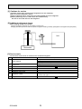
[2] Additional refrigerant charge
When charging directly from cylinder
· Check that cylinder for R410A on the market is syphon type.
· Charging should be performed with the cylinder of syphon standing vertically. (Refrigerant is charged from liquid phase.)
Unit
Gravimeter
[3] Service tools
Use the below service tools as exclusive tools for R410A refrigerant.
No.
Tool name
1
Gauge manifold
2
Charge hose
3
4
5
6
Electronic scale
Gas leak detector
Adaptor for reverse flow check
Refrigerant charge base
7
Refrigerant cylinder
8
Refrigerant recovery equipment
OCH449A
Specifications
· Only for R410A
· Use the existing fitting specifications. (UNF1/2)
· Use high-tension side pressure of 5.3MPa·G or over.
· Only for R410A
· Use pressure performance of 5.09MPa·G or over.
· Use the detector for R134a, R407C or R410A.
· Attach on vacuum pump.
· Only for R410A
· Cylinder with syphon
3
· Top of cylinder (Pink)
3
PART NAMES AND FUNCTIONS
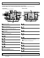
3-1. INDOOR UNIT
Louver
Air outlet
Vane
Air intake
OCH449A
4
Filter
(Inside of Air intake)
3-2. WIRED REMOTE CONTROLLER <PAR-30MAA/PAR-31MAA>
Wired remote controller function
* The functions which can be used are restricted according to the model.
Function
Body
: Supported
PAR-30MAA/PAR-31MAA
Slim
Product size H × W × D (mm)
LCD
: Unsupported
PAR-21MAA
City multi
120 × 120 × 19
120 × 130 × 19
Full Dot LCD
Partial Dot LCD
Backlight
Energy-saving
Energy-saving operation schedule
Automatic return to the preset temperature
Restriction
Setting the temperature range restriction
Function
Operation lock function
Weekly timer
On / Off timer
High Power
Manual vane angle
The functions of the function buttons change depending on
the screen. Refer to the button function guide that appears
at the bottom of the LCD for the functions they serve on a
given screen.
When the system is centrally controlled, the button function
guide that corresponds to the locked button will not appear.
<Main display>
<Main menu>
Fri
Room
Cool
Set temp.
Auto
Mode
Temp.
Fan
Function buttons
F1
F2
F3
Main menu
Vane·Louver·Vent. (Lossnay)
High power
Timer
Weekly timer
OU silent mode
Main display:
Cursor
Page
Function guide
F4
ON / OFF lamp
ON / OFF button
This lamp lights up in green while the unit is in operation.
It blinks while the remote controller is starting up or when
there is an error.
Press to turn ON/OFF the indoor unit.
SELECT button
Press to save the setting.
Function button F1
RETURN button
Main display : Press to change the operation mode.
Main menu : Press to move the cursor down.
Press to return to the previous screen.
Function button F2
MENU button
Main display : Press to decrease temperature.
Main menu : Press to move the cursor up.
Press to bring up the Main menu.
Backlit LCD
Operation settings will appear.
When the backlight is off, pressing any button turns the
backlight on and it will stay lit for a certain period of time
depending on the screen.
When the backlight is off, pressing any button turns
the backlight on and does not perform its function.
(except for the
(ON / OFF) button)
OCH449A
Main
5
Function button F3
Main display : Press to increase temperature.
Main menu : Press to go to the previous page.
Function button F4
Main display : Press to change the fan speed.
Main menu : Press to go to the next page.
The main display can be displayed in two different modes: "Full" and "Basic".
The factory setting is "Full". To switch to the "Basic" mode, change the setting on the Main display setting.
<Full mode>
<Basic mode>
* All icons are displayed for explanation.
Fri
Fri
Cool
Room
Cool
Set temp.
Mode
Temp.
Set temp.
Auto
Auto
Mode
Fan
Temp.
Fan
Operation mode
Indoor unit operation mode appears here.
Appears when the buttons are locked.
Preset temperature
Preset temperature appears here.
Clock (See the Installation Manual.)
Appears when the On/Off timer or Night setback function is
enabled.
Current time appears here.
Fan speed
Fan speed setting appears here.
Appears when the Weekly timer is enabled.
Button function guide
Functions of the corresponding buttons appear here.
Appears while the units are operated in the energy-save
mode.
Appears when the ON/OFF operation is centrally controlled.
Appears when the operation mode is centrally controlled.
Appears when the built-in thermistor on the remote controller is activated to monitor the room temperature.
appears when the thermistor on the indoor unit is activated to monitor the room temperature.
Appears when the preset temperature is centrally controlled.
Indicates the vane setting.
Appears when the f lter reset function is centrally controlled.
Indicates the louver setting.
Indicates when f lter needs maintenance.
Room temperature
(See the Installation Manual.)
Indicates the ventilation setting.
Current room temperature appears here.
Appears when the preset temperature range is restricted.
Most settings (except ON / OFF, mode, fan speed, temperature) can be made from the Menu screen.
OCH449A
6
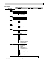
Menu structure
Main menu
Press the MENU button.
Move the cursor to the desired item with the
F1
and
F2
buttons, and press the SELECT button.
Vane · Louver · Vent. (Lossnay)
High power
Timer
On / Off timer
Auto-Off timer
Filter information
Error information
Weekly timer
Energy saving
Auto return
Schedule
Night setback
Restriction
Temp. range
Operation lock
Maintenance
Auto descending panel
Manual vane angle
Initial setting
Main / Sub
Clock
Main display
Contrast
Display details
Auto mode
Administrator password
Language selection
Service
Service menu
Test run
Drain pump test run
Input maintenance info.
Function setting
Lossnay (City Multi only)
Check
Self check
Maintenance password
Remote controller check
Not all functions are available on all models of indoor units.
OCH449A
7
Main menu list
Setting and display items
Setting details
Vane · Louver · Vent.
(Lossnay)
Use to set the vane angle.
• Select a desired vane setting from f ve different settings.
Use to turn ON / OFF the louver.
• Select a desired setting from "ON" and "OFF."
Use to set the amount of ventilation.
• Select a desired setting from "Off," "Low," and "High."
High power
Use to reach the comfortable room temperature quickly.
• Units can be operated in the High-power mode for up to 30 minutes.
Timer
On/Off timer
Use to set the operation On/Off times.
• Time can be set in 5-minute increments.
* Clock setting is required.
Auto-Off
timer
Use to set the Auto-Off time.
• Time can be set to a value from 30 to 240 in 10-minute increments.
Filter information
Use to check the f lter status.
• The f lter sign can be reset.
Error information
Use to check error information when an error occurs.
• Error code, error source, refrigerant address, unit model, manufacturing number, contact
information (dealer's phone number) can be displayed.
* The unit model, manufacturing number, and contact information need to be registered in
advance to be displayed.
Weekly timer
Use to set the weekly operation On / Off times.
• Up to eight operation patterns can be set for each day.
* Clock setting is required.
* Not valid when the On/Off timer is enabled.
Energy
saving
Auto return
Use to get the units to operate at the preset temperature after performing energy-save
operation for a specif ed time period.
• Time can be set to a value from 30 and 120 in 10-minute increments.
* This function will not be valid when the preset temperature ranges are restricted.
Schedule
Set the start/stop times to operate the units in the energy-save mode for each day of the
week, and set the energy-saving rate.
• Up to four energy-save operation patterns can be set for each day.
• Time can be set in 5-minute increments.
• Energy-saving rate can be set to a value from 0% or 50 to 90% in 10% increments.
* Clock setting is required.
Night setback
Restriction
Use to make Night setback settings.
• Select "Yes" to enable the setting, and "No" to disable the setting. The temperature range and
the start/stop times can be set.
* Clock setting is required.
Temp. range
Use to restrict the preset temperature range.
• Different temperature ranges can be set for different operation modes.
Operation
lock
Use to lock selected functions.
• The locked functions cannot be operated.
Maintenance Auto
descending
panel
Manual
vane angle
Initial setting Main/Sub
Clock
Auto descending panel (Optional parts) Up / Down you can do.
Use to set the vane angle for each vane to a f xed position.
When connecting two remote controllers, one of them needs to be designated as a sub
controller.
Use to set the current time.
Main display Use to switch between "Full" and "Basic" modes for the Main display.
• The default setting is "Full."
Contrast
OCH449A
Use to adjust screen contrast.
8
Setting and display items
Initial setting Display
details
Auto mode
Setting details
Make the settings for the remote controller related items as necessary.
Clock: The factory settings are "Yes" and "24h" format.
Temperature: Set either Celsius (°C) or Fahrenheit (°F).
Room temp. : Set Show or Hide.
Auto mode: Set the Auto mode display or Only Auto display.
Whether or not to use the AUTO mode can be selected by using the button.
This setting is valid only when indoor units with the AUTO mode function are connected.
Administrator The administrator password is required to make the settings for the following items.
password
• Timer setting • Energy-save setting • Weekly timer setting
• Restriction setting • Outdoor unit silent mode setting • Night set back
Service
Language
selection
Test run
Use to select the desired language.
Select "Test run" from the Service menu to bring up the Test run menu.
• Test run • Drain pump test run
Input
Select "Input maintenance Info." from the Service menu to bring up the Maintenance
maintenance information screen.
The following settings can be made from the Maintenance Information screen.
• Model name input • Serial No. input • Dealer information input
Function
Make the settings for the indoor unit functions via the remote controller as necessary.
setting
This setting is required only when the operation of City Multi units is interlocked with
LOSSNAY
LOSSNAY units.
setting
(City Multi only)
Check
Error history: Display the error history and execute delete error history.
Refrigerant leak check: Refrigerant leaks can be judged.
Smooth maintenance: The indoor and outdoor maintenance data can be displayed.
Request cord: Details of the operation data including each thermistor temperature and error
history can be checked.
Self check
Error history of each unit can be checked via the remote controller.
Maintenance Take the following steps to change the maintenance password.
password
Remote
When the remote controller does not work properly, use the remote controller checking
controller
function to troublushoot the problem.
check
OCH449A
9
3-3. WIRED REMOTE CONTROLLER <PAR-21MAA>
“Sensor” indication
Display Section
For purposes of this explanation,
all parts of the display are shown.
During actual operation, only the
relevant items will be lit.
Identifies the current operation
Displayed when the remote controller
sensor is used.
Day-of-Week
Shows the current day of the week.
Time/Timer Display
“Locked” indicator
Shows the current time, unless the simple or Auto Off
timer is set.
If the simple or Auto Off timer is set, the time to be
switched off is shown.
Indicates that remote controller buttons have been locked.
“Clean The Filter” indicator
Shows the operating mode, etc.
*Multilanguage display is available.
To be displayed on when it is time to
clean the filter.
TIME SUN MON TUE WED THU FRI SAT
TIMER
Hr
ON
AFTER
Indicates that operation from the
remote controller has been prohibited by a master controller.
“Timer is Off” indicator
Indicates that the timer is off.
WEEKLY
SIMPLE
AUTO OFF
ONLY1Hr.
Shows the target temperature.
The indicator comes on if the corresponding timer is set.
Fan Speed indicator
Shows the selected fan speed.
Up/Down Air Direction indicator
The indicator shows the direction of the outcoming airflow.
“One Hour Only” indicator
Temperature Setting
FUNCTION
FILTER
°F°C
°F°C
“Centrally Controlled” indicator
Timer indicators
AFTER OFF
ERROR CODE
Displayed if the airflow is set to
Low or downward during COOL
or DRY mode. (Operation varies
according to model.)
The indicator goes off in one hour,
at which time the airflow direction
also changes.
Room Temperature display
Shows the room temperature. The room
temperature display range is 8 - 39°C.
The display blinks if the temperature
is less than 8°C or 39°C or more.
Ventilation indicator
Appears when the unit is running in
Ventilation mode.
Louver display
Indicates the action of the swing louver.
Does not appear if the louver is not
running.
(Power On indicator)
Indicates that the power is on.
Operation Section
ON/OFF button
Temperature setting buttons
Down
Fan Speed button
Up
Timer Menu button
(Monitor/Set button)
Filter
button
(<Enter> button)
Mode button (Return button)
TEMP.
ON/OFF
Set Time buttons
Check button (Clear button)
Back
Ahead
Timer On/Off button
(Set Day button)
Test Run button
MENU
BACK
PAR-21MAA
MONITOR/SET
ON/OFF
FILTER
DAY
CHECK TEST
OPERATION
CLOCK
CLEAR
Airflow Up/Down button
Louver button
(
Operation button)
To return operation
number
Opening the
cover
Built-in temperature sensor
Ventilation button
( Operation button)
To go to next operation
number
Note:
● “PLEASE WAIT” message
This message is displayed for approximately 3 minutes when power is supplied to the indoor unit or when the unit is recovering from a power failure.
● “NOT AVAILABLE” message
This message is displayed if an invalid button is pressed (to operate a function that the indoor unit does not have).
If a single remote controller is used to operate multiple indoor units simultaneously that are different types, this message will not be displayed as
far as any of the indoor units is equipped with the function.
OCH449A
10
4
SPECIFICATION
4-1. SPECIFICATIONS
Model
Power source
Cooling capacity
(Nominal)
PCFY-P40VKM-E
Power input
Current input
Heating capacity
(Nominal )
External finish
Power input
Current input
*1
*1
*1
*2
kW
kcal/h
Btu/h
kcal/h
kW
A
*3 kW
*3 kcal/h
*3 Btu/h
kW
A
External dimensions H x W x D
Net weight
Heat exchanger
FAN
Type x quantity
External
static press.
Motor type
Motor output
Driving mechanism
Airflow rate
(Low-Mid2-Mid1-High)
Noise level (Low-Mid2-Mid1-High)
(measured in anechoic room)
Insulation material
Air filter
Protection device
Refrigerant control device
Connectable outdoor unit
Diameter of
Liquid
refrigerant pipe
Gas
Field drain pipe size
Standard
Document
attachment
Accessory
mm
in.
kg (lb)
4.5
3,900
15,400
4,000
0.040
0.28
5.0
4,300
17,100
0.040
0.28
230×960×680
9-1/16×37-13/16×26-3/4
24 (53)
Sirocco fan × 2
m /min
L/s
cfm
dB <A>
mm(in.)
mm(in.)
mm(in.)
Drain pump kit
High efficiency filter
Wireless remote controller kit
Remarks
Installation
0.090
0.095
Direct-driven by motor
14-15-16-18
21-24-26-28
233-250-267-300
350-400-433-467
494-530-565-636
742-847-918-989
31-33-35-37
36-38-41-43
10-11-12-13
167-183-200-217
353-388-424-459
29-32-34-36
Polyeter sheet
PP honeycomb
Fuse
LEV
R410A CITY MULTI
ø9.52 (ø3/8) Flare
ø9.52 (ø3/8) Flare
ø15.88 (ø5/8) Flare
ø19.05 (ø3/4) Flare
O.D. 26mm (1)
ø6.35 (ø1/4) Flare
ø12.7 (ø1/2) Flare
PAC-SH83DM-E
PAC-SH88KF-E
21-24-27-31
350-400-450-517
742-847-953-1095
36-39-42-44
ø9.52 (ø3/8) Flare
ø19.05 (ø3/4) Flare
PAC-SH84DM-E
PAC-SH89KF-E
PAC-SH90KF-E
PAR-SL94B-E
Details on foundation work, insulation work, electrical wiring, power source switch, and other items shall be referred to the
Installation Manual.
27°CDB/19°CWB (81°FDB/66°FWB)
35°CDB (95°FDB)
7.5 m (24-9/16 ft)
0 m (0 ft)
*2 Nominal cooling conditions
27°CDB/19.5°CWB (81°FDB/67°FWB)
35°CDB (95°FDB)
5 m (16-3/8 ft)
0 m (0 ft)
* Nominal conditions *1, *3 are subject to JIS B8615-1.
* Due to continuing improvement, above specification may be subject to change without notice.
OCH449A
0.160
Installation Manual, Instruction Book
*1 Nominal cooling conditions
Indoor :
Outdoor :
Pipe length :
Level difference :
14.0
12,000
47,800
12,500
0.110
0.76
16.0
13,800
54,600
0.110
0.76
0
0
DC motor
kW
3
PCFY-P125VKM-E
230×1280×680
230×1600×680
9-1/16×50-3/8×26-3/4
9-1/16×63×26-3/4
32 (71)
36 (79)
38 (84)
Cross fin (Aluminum fin and copper tube)
Sirocco fan × 3
Sirocco fan × 4
Pa
mmH 2O
Optional parts
Note :
PCFY-P63VKM-E
PCFY-P100VKM-E
1-phase 220-240V 50Hz, 1-phase 220V 60Hz
7.1
11.2
6,100
9,600
24,200
38,200
6,300
10,000
0.050
0.090
0.33
0.65
8.0
12.5
6,900
10,800
27,300
42,700
0.050
0.090
0.33
0.65
MUNSELL (6.4Y 8.9/0.4)
11
*3 Nominal heating conditions
20°CDB (68°FDB)
7°CDB/6°CWB (45°FDB/43°FWB)
7.5 m (24-9/16 ft)
0 m (0 ft)
Unit converter
kcal/h = kW × 860
Btu/h = kW × 3,412
cfm = m3/min × 35.31
lb = kg/0.4536
*Above specification data is
subject to rounding variation.
4-2. ELECTRICAL PARTS SPECIFICATIONS
Service Ref.
Symbol
Parts name
PCFY-P40VKM-E
PCFY-P40VKM-ER1
PCFY-P100VKM-E
PCFY-P125VKM-E
PCFY-P100VKM-ER1
PCFY-P125VKM-ER1
PCFY-P63VKM-E
PCFY-P63VKM-ER1
Room temperature
thermistor
TH21
Resistance 0°C/15kΩ, 10°C/9.6kΩ, 20°C/6.3kΩ, 25°C/5.4kΩ, 30°C/4.3kΩ, 40°C/3.0kΩ
Liquid pipe thermistor
TH22
Resistance 0°C/15kΩ, 10°C/9.6kΩ, 20°C/6.3kΩ, 25°C/5.4kΩ, 30°C/4.3kΩ, 40°C/3.0kΩ
Gas pipe thermistor
TH23
Resistance 0°C/15kΩ, 10°C/9.6kΩ, 20°C/6.3kΩ, 25°C/5.4kΩ, 30°C/4.3kΩ, 40°C/3.0kΩ
Fuse
(Indoor controller board)
FUSE
250V 6.3A
8-pole OUTPUT 90W
8-pole OUTPUT 160W
8-pole OUTPUT 95W
Fan motor
MF
Vane motor
MV
MSBPC20
DC12V 300Ω/phase
Drain-pump
(Option)
DP
INPUT 12/10.8W 24 /Hr
Drain float switch
FS
Open / Short detection DC 5V
DC12V Stepping motor drive
Port dimension ø3.2 (0~2000pulse)
EFM-40YGME
DC12V Stepping motor drive
Port dimension ø5.2 (0~2000pulse)
EFM-80YGME
Linear expansion valve
LEV
Power supply terminal
block
TB2
Transmission terminal
block
TB5
(M1, M2, S) Rated to 250V 20A *
MA remote controller
terminal block
TB15
(1, 2) Rated to 250V 10A *
(L, N,
) Rated to 330V 30A *
* Refer to WIRING DIAGRAM for the supplied voltage.
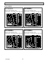
4-3. SOUND LEVEL
PCFY-P·VKM-E
Service Ref.
PCFY-P40VKM-E
PCFY-P40VKM-ER1
PCFY-P63VKM-E
PCFY-P63VKM-ER1
PCFY-P100VKM-E
PCFY-P100VKM-ER1
PCFY-P125VKM-E
PCFY-P125VKM-ER1
1m
Measurement
location
1m
* Measured in anechoic room.
OCH449A
12
Sound level at anechoic room : Low-Mid2-Mid1-High
Sound level dB (A)
29-32-34-36
31-33-35-37
36-38-41-43
36-39-42-44
4-4. NC CURVES
65.0
60.0
NC-60
55.0
50.0
NC-50
45.0
40.0
NC-40
35.0
30.0
NC-30
25.0
20.0
15.0
10.0
63
Approximate minimum
audible limit on
continuous noise
125
250
NC-20
500
1k
2k
4k
Octave band center frequencies (Hz)
Octave band pressure level (dB) 0dB=20μPa
Middle2
Low
70.0
65.0
60.0
NC-60
55.0
50.0
NC-50
45.0
40.0
NC-40
35.0
30.0
NC-30
25.0
20.0
15.0
10.0
63
Approximate minimum
audible limit on
continuous noise
125
250
NC-20
500
1k
2k
4k
Octave band center frequencies (Hz)
OCH449A
65.0
60.0
13
NC-60
55.0
50.0
NC-50
45.0
40.0
NC-40
35.0
30.0
NC-30
25.0
20.0
15.0
Approximate minimum
audible limit on
continuous noise
125
250
NC-20
500
1k
2k
Octave band center frequencies (Hz)
4k
8k
PCFY-P125VKM-E
PCFY-P125VKM-ER1
External static pressure : 0Pa
Power source : 220,230,240V, 50Hz / 220V, 60Hz
Middle2
Low
High
Middle1
70.0
65.0
60.0
NC-60
55.0
50.0
NC-50
45.0
40.0
NC-40
35.0
30.0
NC-30
25.0
20.0
15.0
10.0
63
8k
Middle2
Low
High
Middle1
70.0
10.0
63
8k
PCFY-P100VKM-E
PCFY-P100VKM-ER1
External static pressure : 0Pa
Power source : 220,230,240V, 50Hz / 220V, 60Hz
High
Middle1
Octave band pressure level (dB) 0dB=20μPa
Middle2
Low
High
Middle1
70.0
PCFY-P63VKM-E
PCFY-P63VKM-ER1
External static pressure : 0Pa
Power source : 220,230,240V, 50Hz / 220V, 60Hz
Octave band pressure level (dB) 0dB=20μPa
Octave band pressure level (dB) 0dB=20μPa
PCFY-P40VKM-E
PCFY-P40VKM-ER1
External static pressure : 0Pa
Power source : 220,230,240V, 50Hz / 220V, 60Hz
Approximate minimum
audible limit on
continuous noise
125
250
NC-20
500
1k
2k
4k
Octave band center frequencies (Hz)
8k
4-5. FRESH AIR INTAKE AMOUNT & STATIC PRESSURE CHARACTERISTICS
PCFY-P63VKM-E
PCFY-P63VKM-ER1
PCFY-P40VKM-E
PCFY-P40VKM-ER1
50
0
-50
-100
-150
-200
-250
-300
0
Static pressure[Pa]
Static pressure[Pa]
50
-50
-100
-150
-200
-250
-300
0
1
2
3
4
0
1
A
-50
Q
-100
-150
C
0
Duct characteristics
at site
2
C
A
-200
E
-250
Q
2
Airflow rate[m³/min]
3
4
3
D
1
A
Static pressure[Pa]
Curve in the
graphs
B
1
0
0
Q
Qa
OCH449A
4
How to read curves
50
-300
3
Airflow rate[m³/min]
Airflow rate[m³/min]
PCFY-P100, 125VKM-E
PCFY-P100, 125VKM-ER1
2
14
Q…Designed amount of fresh air intake
<m3/min>
A…Static pressure loss of fresh air
intake duct system with airflow
amount Q
<Pa>
…
B Forced static pressure at air conditioner
inlet with airflow amount Q
<Pa>
C…Static pressure of booster fan with
airflow amount Q
<Pa>
D…Static pressure loss increase amount
of fresh air intake duct system for
airflow amount Q
<Pa>
E…Static pressure of indoor unit with
airflow amount Q
<Pa>
Qa … Estimated amount of fresh air
3
intake without D
<m /min>
1
2
3
4
5
6
7
8
9
190
121
75
3
461
25
Ø1
15
2
8
48
246
233
120°
7
387
18
85
260
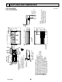
(Drainage)
When drain socket
is installed
38
38
Drainage pipe connection(26mmI.D.)
Drainage pipe connection(for the left arrangement)
Knock out hole for left drain-piping arrangement
Refrigerant-pipe connection(gas pipe side/flared connection)
Refrigerant-pipe connection(liquid pipe side/flared connection)
Knock out hole for upper drain pipe arrangement
Knock out hole for fresh air intake Ø100
Knock out hole for wiring arrangement 2-Ø22
Knock out hole for wiring arrangement 2-Ø26
Accessory···Drain socket (I.D. 26)
Electrical box
9
24
37
138
2
2
Air intake
86
4
126
1
1
190
Ceiling
169
In case of the rear pipe arrangement,make sure to
remove the shaded portions from the independent piece.
Then put the independent piece back in initial
position.(The heat exchanger might be clogged because of dust)
When electrical box
is pulled down
46
76
124
2
8
5
Air outlet
878
853
960
917(Suspension bolt pitch)
182
140
80
85
2
62
6
680
230
150
18
[FRONT VIEW]
88
84
254
320
195
57
OCH449A
680
Electrical box
5
10
51
184
(Drainage)
When drain socket
is installed
(liquid Ø6.35)
(gas Ø12.7)
NOTES.
1.Use M10 or W3/8 screw for anchor bolt.
2.Please be sure when installing the
drain lift up mechanism(option parts),
refrigerant pipe will be only upward.
246
233
203
PCFY-P40VKM-E
PCFY-P40VKM-ER1
476
5
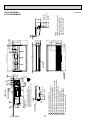
OUTLINES AND DIMENSIONS
Unit : mm
1
2
3
4
5
6
7
8
9
190
75
3
121
Ceiling
461
25
Ø1
8
9
38
38
24
5
16
2
48
246
233
(Drainage)
When drain socket
is installed
85
260
1
138
86
2
4
Drainage pipe connection(26mmI.D.)
Drainage pipe connection(for the left arrangement)
Knock out hole for left drain-piping arrangement
Refrigerant-pipe connection(gas pipe side/flared connection)
Refrigerant-pipe connection(liquid pipe side/flared connection)
Knock out hole for upper drain pipe arrangement
Knock out hole for fresh air intake Ø100
Knock out hole for wiring arrangement 2-Ø22
Knock out hole for wiring arrangement 2-Ø26
Air intake
Accessory···Drain socket (I.D. 26)
Electrical box
8
7
387
18
120°
In case of the rear pipe arrangement,make sure to
remove the shaded portions from the independent piece.
Then put the independent piece back in initial
position.(The heat exchanger might be clogged because of dust)
When electrical box
is pulled down
46
76
124
2
169
37
Electrical box
126
1
190
[FRONT VIEW]
2
Air outlet
1198
1173
1280
1237(Suspension bolt pitch)
182
140
80
85
2
62
88
84
254
320
195
57
6
680
230
680
OCH449A
476
5
10
180
246
233
200
(Drainage)
When drain socket
is installed
(liquid Ø9.52)
(gas Ø15.88)
236
NOTES.
1.Use M10 or W3/8 screw for anchor bolt.
2.Please be sure when installing the
drain lift up mechanism(option parts),
refrigerant pipe will be only upward.
51
PCFY-P63VKM-E
PCFY-P63VKM-ER1
Unit : mm
150
18
75
190
46
Electrical box
461
25
Ø1
Ceiling
Electrical box
2
8
48
246
233
38
7
387
18
120°
85
260
1
When drain socket
is installed
9
5
38
24
(Drainage)
In case of the rear pipe arrangement,make sure to
remove the shaded portions from the independent piece.
Then put the independent piece back in initial
position.(The heat exchanger might be clogged because of dust)
When electrical box
is pulled down
3
169
37
76
124
71
8
138
86
2
4
Air intake
126
2
121
1
190
2
Air outlet
1518
1493
1600
1557
(Suspension bolt pitch)
Knock out hole for upper drain pipe arrangement
Knock out hole for fresh air intake Ø100
Knock out hole for wiring arrangement 2-Ø22
Knock out hole for wiring arrangement 2-Ø26
Accessory···Drain socket (I.D. 26)
150
[FRONT VIEW]
6
7
8
9
182
140
80
85
2
62
6
680
230
Drainage pipe connection(26mmI.D.)
Drainage pipe connection(for the left arrangement)
Knock out hole for left drain-piping arrangement
Refrigerant-pipe connection(gas pipe side/flared connection)
Refrigerant-pipe connection(liquid pipe side/flared connection)
88
84
254
320
195
57
17
680
1
2
3
4
5
5
10
180
246
233
200
(Drainage)
When drain socket
is installed
(liquid Ø9.52)
(gas Ø15.88)
NOTES.
1.Use M10 or W3/8 screw for anchor bolt.
2.Please be sure when installing the
drain lift up mechanism(option parts),
refrigerant pipe will be only upward.
51
236
OCH449A
476
PCFY-P100VKM-E
PCFY-P125VKM-E
PCFY-P100VKM-ER1
PCFY-P125VKM-ER1
Unit : mm
18
6
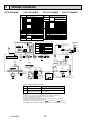
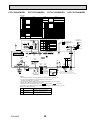
WIRING DIAGRAM
PCFY-P40VKM-E
PCFY-P63VKM-E
SYMBOL
I. B
CN27
CN32
CN51
CN52
DSA
FUSE
SW2
SW3
SW4
SWE
X1
ZNR01,02
LEV
DCL
MF
MV
TB2
TB5
TB15
TH21
A.B
SWA
1 2 3 4 5 6 7 8 910
SW12 SW11
9 0 1
7 8
7 8
2 3
2 3
4
5 6
5 6
10ths
DIGIT
5
1s
DIGIT
MODELS
1
8
(RED)
ADDRESS
SW14 CN82
SWC E F 0 1 2
3456
9 0 1
BRANCH
No.
1
8
1
19 17 15 13 11 9 7 5 3 1
3
VANE CNV
(WHT)
Pair No.
1
P40
P63
ON
OFF
P100
ON
OFF
P125
ON
OFF
8
ADDRESS
CN81
(RED)
1
LEV
CN60
(WHT)
CN52
1 (GRN) 5
A. B
SWA
SWC
SW1
SW11
SW12
SW14
OPTIONAL PARTS
W.B
BZ
LED1
LED2
RU
SW1
SW2
DP
FS
PCB FOR WIRELESS REMOTE CONTROLLER
BUZZER
LED (OPERATION INDICATION : GREEN)
LED (PREPARATION FOR HEATING : ORANGE)
RECEVING UNIT
EMERGENCY OPERATION (HEAT / DOWN)
EMERGENCY OPERATION (COOL / UP)
DRAIN PUMP
DRAIN FLOAT SWITCH
SW3
ON
OFF
ON
OFF
1 2 3 4 5 6
(SHIELD)
RED TB2
BLU L
GRN/YLW N
1 2 3 4 5 6
ON
OFF
1 2 3 4 5 6
BREAKER
(16A)
FUSE(16A)
DCL
1 2 3 4 5 6 7 8 9 10
POWER SUPPLY
~/N 220-240V 50Hz
220V 60Hz
TO OUTDOOR UNIT
BC CONTROLLER
REMOTE CONTROLLER
DC24-30V
1 2 3 4 5 6 7 8 9 10
I.B
See fig: 1
1
ON
OFF
4
ADDRESS
CN42
(RED)
SW3
SW4
1 2 3 4 5 6 7 8 910
PULL BOX
TO NEXT
INDOOR UNIT
1 3 5
SW2
12345 123456
ON
OFF
2 1
M-NET
CN2M
(BLU)
SWE
CND
(BLK)
DSA
ZNR02
DC311~339V
RECTIFICATION
FUSE
U
ZNR01 U
WIRELESS
CN90
(WHT)
1
BLU TB5
M1
BLU
M2
S
1 2 3 4 5 6 7 8 9 10
OFF ON
MA REMOCON
CN3A
(BLU)
3
TH23
1 2 3 4 5 6
4
LED2
1
NAME
THERMISTOR PIPE TEMP. DETECTION / LIQUID
(0°C / 15kΩ, 25°C / 5.4kΩ)
PIPE TEMP. DETECTION / GAS
(0°C / 15kΩ, 25°C / 5.4kΩ)
ADDRESS BOARD
CEILING HEIGHT SELECTOR
SWITCH
OPTION SELECTOR
MODE SELECTION
ADDRESS SETTING 1s DIGIT
ADDRESS SETTING 10ths DIGIT
BRANCH No.
SYMBOL
TH22
SW2
ON
OFF
CN32
(WHT) J42 J41
20 18 16 14 12 10 8 6 4 2
PCFY-P125VKM-E
< 1> The black square (■) indicates a switch position.
(RED) 4
ADDRESS
CN43
BCD
M
3
2
1
4
MV
SW1
NAME
INDOOR CONTROLLER BOARD
CONNECTOR DAMPER
REMOTE SWITCH
CENTRALLY CONTROL
REMOTE INDICATION
SURGE ABSORBER
FUSE (T6.3AL250V)
CAPACITY CODE
SWITCH
MODE SELECTION
MODEL SELECTION
DRAIN PUMP (TEST MODE)
AUX. RELAY DRAIN PUMP (OPTIONAL PARTS)
VARISTOR
LINEAR EXPANSION VALVE
REACTOR
FAN MOTOR
VANE MOTOR
TERMINAL
POWER SUPPLY
BLOCK
TRANSMISSION
MA-REMOTE CONTROLLER
THERMISTOR ROOM TEMP. DETECTION
(0°C / 15kΩ, 25°C / 5.4kΩ)
789A
ON
OFF
PCFY-P100VKM-E
9
CN25
(WHT)
1 2
LED1
6
CN41
1 (WHT) 4
CN51
1 (WHT) 5
WHT
YLW
ORN
BLU
RED
BRN
6
TB15
BLU 1
BLU 2
9
TO MA-REMOTE
CONTROLLER
DC8.7-13V
M
LEV
LIQUID/PIPE
CN44
1 (WHT) 4
W.B
CNB
BZ
SW1
LED2
SW2
LED1
RU
t°
t°
TH22 TH23
(OPTIONAL PARTS)
INTAKE
CN20
(RED)
FLOAT SW
CN4F
1 (WHT) 4
1 2
When attaching
drain pump
(optional parts),
remove the jumper
connector CN4F
and fit the drain
float switch (FS).
When attaching
drain pump
(optional parts)
FLOAT SW
CN4F
(WHT)
1
1 2
7
FAN
CNMF
(WHT)
4
X1
1
MS
3~
4
FS
CN27
(RED)
t°
TH21
MF
Meaning
LED1
Main power supply
LED2
Power supply for
MA-Remote controller
Function
Main power supply (Indoor unit:220-240V)
Power on → Iamp is lit
Power supply for MA-Remote controller
on → Iamp is lit
NOTES:
1.At servicing for outdoor unit,always follow the wiring diagram of outdoor unit.
2.In case of using MA-Remote controller, please connect to TB15.
(Remote controller wire is non-polar.)
3.In case of using M-NET, please connect to TB5. (Transmission line is non-polar.)
4.Symbol [S] of TB5 is the shield wire connection.
5.Symbols used in wiring diagram above are,
: terminal block,
:connecter.
6.The setting of the SW2 dip switches differs in the capacity. for the detail, refer to the fig: 1.
OCH449A
18
1
M
1~
DP
(OPTIONAL PARTS)
Be sure to turn off the source power
and then disconnect fan motor connector.
(Failure to do so will cause trouble in Fan motor)
LED on indoor board for service
Mark
D.U.M 3
CNP
(BLU)
PCFY-P40VKM-ER1
PCFY-P63VKM-ER1
PCFY-P100VKM-ER1
PCFY-P125VKM-ER1
[LEGEND]
SYMBOL
I. B
CN27
CN32
CN51
CN52
CN105
FUSE
SW2
SW3
SW4
SWE
X1
LEV
DCL
MF
MV
TB2
TB5
TB15
TH21
NAME
INDOOR CONTROLLER BOARD
CONNECTOR DAMPER
REMOTE SWITCH
CENTRALLY CONTROL
REMOTE INDICATION
IT TERMINAL
FUSE (T6.3AL250V)
CAPACITY CODE
SWITCH
MODE SELECTION
MODEL SELECTION
DRAIN PUMP (TEST MODE)
AUX. RELAY DRAIN PUMP (OPTIONAL PARTS)
LINEAR EXPANSION VALVE
REACTOR
FAN MOTOR
VANE MOTOR
TERMINAL
POWER SUPPLY
BLOCK
TRANSMISSION
MA-REMOTE CONTROLLER
THERMISTOR ROOM TEMP. DETECTION
(0°C / 15kΩ, 25°C / 5.4kΩ)
A.B
1 2 3 4 5 6 7 8 910
SW12 SW11
7 8
2 3
2 3
4 5 6
4 5 6
10ths
DIGIT
5
7 8
9 0 1
1s
DIGIT
SW14
SWC
E
F0 1 2
2
1
8
(RED)
ADDRESS
CN82
3456
9 0 1
BRANCH
No.
1
8
20 18 16 14 12 10 8 6 4 2
19 17 15 13 11 9 7 5 3 1
A. B
SWA
SWC
SW1
SW11
SW12
SW14
OPTIONAL PARTS
W.B
BZ
LED1
LED2
RU
SW1
SW2
DP
FS
MODELS
1
BCD
M
SWA
3
2
1
SW1
TH23
3
VANE CNV
(WHT)
Pair No.
1
P40
P63
ON
OFF
P100
ON
OFF
P125
ON
OFF
8
ADDRESS
CN81
(RED)
1
CN52
1 (GRN) 5
ON
OFF
1 2 3 4 5 6
BLU TB5
M1
BLU
M2
S
1 2 3 4 5 6 7 8 9 1 0
(SHIELD)
1 2 3 4 5 6
3
1
ON
OFF
4
ADDRESS
CN42
(RED)
1 2 3 4 5 6 7 8 9 1 0
SW4
I.B
1 2 3 4 5 6 7 8 910
1 3 5
SW2
12345 123456
ON
OFF
CND
(BLK)
2 1
M-NET
CN2M
(BLU)
SWE
FUSE
1 CN105 5
WIRELESS
CN90
(WHT)
1
(RED)
9
CN25
(WHT)
1 2
LED1
6
CN51
1 (WHT) 5
WHT
YLW
ORN
BLU
RED
BRN
6
CN41
1 (WHT) 4
TB15
ORN 1
ORN 2
LIQUID/PIPE
CN44
1 (WHT) 4
9
TO MA-REMOTE
CONTROLLER
DC8.7-13V
M
CNB
BZ
SW1
LED2
SW2
LED1
RU
W.B
LEV
(OPTIONAL PARTS)
t°
t°
TH22 TH23
INTAKE
CN20
(RED)
FLOAT SW
CN4F
1 (WHT) 4
When attaching
drain pump
(optional parts),
remove the jumper
connector CN4F
and fit the drain
float switch (FS).
1 2
When attaching
drain pump
(optional parts)
FLOAT SW
CN4F
(WHT)
1
1 2
7
FAN
CNMF
(WHT)
LED on indoor board for service
Mark
Meaning
LED1
Main power supply
LED2
Power supply for
MA-Remote controller
Function
Main Power supply (Indoor unit:220-240V)
power on → lamp is lit
Power supply for MA-Remote controller
on → lamp is lit
19
X1
4
MS
3~
4
FS
CN27
(RED)
t°
TH21
MF
1 D.U.M
CNP 3
(BLU)
1
M
1~
DP
(OPTIONAL PARTS)
Be sure to turn off the source power
and then disconnect fan motor connector.
(Failure to do so will cause trouble in Fan motor)
NOTES:
1. At servicing for outdoor unit, always follow the wiring diagram of outdoor unit.
2. In case of using MA-Remote controller, please connect to TB15.
(Remote controller wire is non-polar.)
3. In case of using M-NET, please connect to TB5. (Transmission line is non-polar.)
4. Symbol [S] of TB5 is the shield wire connection.
5. Symbols used in wiring diagram above are,
: terminal block,
: connecter.
6. The setting of the SW2 dip switches differs in the capacity. For the detail, refer to fig < 1>.
OCH449A
RED TB2
BLU L
GRN/YLW N
See fig: 1
SW3
BREAKER
(16A)
FUSE(16A)
DCL
1 2 3 4 5 6 7 8 9 1 0
1 2 3 4 5 6
ON
OFF
POWER SUPPLY
~/N 220-240V 50Hz
220V 60Hz
TO OUTDOOR UNIT
BC CONTROLLER
REMOTE CONTROLLER
DC24-30V
OFF ON
MA REMOCON
CN3A
(BLU)
LEV
CN60
(WHT)
SW3
ON
OFF
1 2 3 4 5 6
4
LED2
1
PCB FOR WIRELESS REMOTE CONTROLLER
BUZZER
LED (OPERATION INDICATION : GREEN)
LED (PREPARATION FOR HEATING : ORANGE)
RECEVING UNIT
EMERGENCY OPERATION (HEAT / DOWN)
EMERGENCY OPERATION (COOL / UP)
DRAIN PUMP
DRAIN FLOAT SWITCH
SW2
ON
OFF
CN32
(WHT) J42 J41
1
NAME
THERMISTOR PIPE TEMP. DETECTION / LIQUID
(0°C / 15kΩ, 25°C / 5.4kΩ)
PIPE TEMP. DETECTION / GAS
(0°C / 15kΩ, 25°C / 5.4kΩ)
ADDRESS BOARD
CEILING HEIGHT SELECTOR
SWITCH
OPTION SELECTOR
MODE SELECTION
ADDRESS SETTING 1s DIGIT
ADDRESS SETTING 10ths DIGIT
BRANCH No.
The black square (■) indicates a switch position. < 1>
(RED) 4
ADDRESS
CN43
789A
ON
OFF
MV
SYMBOL
TH22
PULL BOX
TO NEXT
INDOOR UNIT
7
REFRIGERANT SYSTEM DIAGRAM
PCFY-P40VKM-E
PCFY-P40VKM-ER1
PCFY-P63VKM-E
PCFY-P63VKM-ER1
PCFY-P100VKM-E
PCFY-P100VKM-ER1
PCFY-P125VKM-E
PCFY-P125VKM-ER1
Refrigerant flow in cooling
Refrigerant flow in heating
Gas pipe thermistor TH23
Strainer (#100 mesh)
Gas pipe
Flare connection
Liquid pipe thermistor TH22
Liquid pipe
Linear expansion valve
Strainer1 (#50 mesh)
Strainer2 (#100 mesh)
Strainer (#100 mesh)
Room temparature thermistor TH21
Heat exchanger
Service Ref.
Item
PCFY-P40VKM-E
PCFY-P40VKM-ER1
Unit : mm (inch)
PCFY-P63VKM-E, PCFY-P63VKM-ER1
PCFY-P100VKM-E, PCFY-P100VKM-ER1
PCFY-P125VKM-E, PCFY-P125VKM-ER1
Gas pipe
ø12.7 (1/2)
ø15.88 (5/8)
Liquid pipe
ø6.35 (1/4)
ø9.52 (3/8)
OCH449A
20
8
TROUBLESHOOTING
8-1. HOW TO CHECK THE PARTS
PCFY-P63VKM-E
PCFY-P40VKM-E
PCFY-P40VKM-ER1 PCFY-P63VKM-ER1
PCFY-P100VKM-E
PCFY-P100VKM-ER1
Parts name
Check points
Room temperature
thermistor (TH21)
Liquid pipe thermistor
(TH22)
Gas pipe thermistor
(TH23)
Disconnect the connector then measure the resistance with a tester.
(At the ambient temperature of 10°C~30°C)
Vane motor (MV)
Measure the resistance between the terminals with a tester.
(At the ambient temperature of 20°C~30°C
White
MV
Orange
Red
Blue
Yellow
Drain pump (DP)
(Option)
1
3
Drain float switch (FS)
Moving part
1
2
3
PCFY-P125VKM-E
PCFY-P125VKM-ER1
Normal
Abnormal
4.3kΩ~9.6kΩ
Open or short
Connector
Red - Yellow
Red - Blue
Red - Orange
Red - White
(Refer to Thermistor characteristic graph.)
Normal
Abnormal
300Ω
Open or short
Measure the resistance between the terminals with a tester.
(Winding temperature 20°C)
Normal
290Ω
Abnormal
Open or short
Measure the resistance between the terminals with a tester.
State of moving part
Normal
Abnormal
UP
Short
Other than short
DOWN
Open
Other than open
Switch
Magnet
4
Moving part
(Option)
Linear expansion
Blue
valve (LEV)
M
Brown
Yellow
Disconnect the connector then measure the resistance value with a tester.
Normal
White-Red
Yellow-Brown Orange-Red
200Ω ±10%
White Red Orange
OCH449A
21
Abnormal
Blue-Brown
Open or short
Refer to 8-1-2.
8-1-1. Thermistor
<Thermistor characteristic graph>
Thermistor for
lower temperature
< Thermistor for lower temperature >
Room temperature thermistor (TH21)
Liquid pipe temperature thermistor (TH22)
Gas pipe temperature thermistor (TH23)
0°C
10°C
20°C
25°C
30°C
40°C
8-1-2.
1
273+t
40
Resistance (kΩ)
Thermistor R0=15kΩ ± 3%
Fixed number of B=3480 ± 2%
Rt=15exp { 3480 (
50
1
)}
273
15kΩ
9.6kΩ
6.3kΩ
5.4kΩ
4.3kΩ
3.0kΩ
30
20
10
0
-20
-10
0
10 20 30
Temperature (°C)
40
50
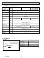
Linear expansion valve
Operation summary of the linear expansion valve
• Linear expansion valves open/close through the use of a stepping motor after receiving the pulse signal from the indoor
controller board.
• Valve position can be changed in proportion to the number of pulse signals.
<Connection between the indoor controller board and the linear expansion valve>
Controller board
DC12V
Brown
6
Blue
Red
5
Brown
Blue
4
ø4
Yellow
Orange
3
ø3
Yellow
2
ø2
White
1
ø1
Linear expansion valve
4
M
1
ø4
6
ø2
ø1 5 ø3 2
White Red
3
Orange
Drive circuit
Connector (CN60)
Note : Since the number of the connector at the controller board side and the relay connector are different, follow the color of
the lead wire.
OCH449A
22
<Output pulse signal and the valve operation>
Output
Output
(Phase)
1
2
3
4
[1
ON
OFF
OFF
ON
[2
ON
ON
OFF
OFF
[3
OFF
ON
ON
OFF
[4
OFF
OFF
ON
ON
Linear expansion valve operation
Open
C
Valve position (capacity)
Close
A
E
Close
Note:
· When linear expansion valve operation stops, all output phase
become OFF.
· At phase interruption or when phase does not shift in order, motor
does not rotate smoothly and motor will lock and vibrate.
· When the switch is turned on, 2200 pulse closing valve signal will be
sent till it goes to point in order to define the valve position.
D
Open
Closing a valve : 1 → 2 → 3 → 4 → 1
Opening a valve : 4 → 3 → 2 → 1 → 4
The output pulse shifts in above order.
When the valve moves smoothly, there is no sound or vibration
occurring from the linear expansion valves, however, when the pulse
number moves from to or when the valve is locked, more sound
can be heard than in a normal situation.
· Sound can be detected by placing the ear against the screw driver
handle while putting the screw driver tip to the linear expansion
valve.
Outdoor unit R410A model
: 1400 pulse
Outdoor unit R22/R407C model : 2000 pulse
Opening a valve
all the way
Pulse number
B
Extra tightening (200~800 pulse)
Troubleshooting
Symptom
Check points
Countermeasures
Operation circuit
failure of the micro
processor
Disconnect the connector on the controller board, then con- Exchange the indoor connect LED for checking.
troller board at drive circuit
6
5
failure.
4
3
2
1
1kΩ LED
When power is turned on, pulse signals will output for 10
seconds. There must be some defects in the operation circuit
if the LED does not light while the signals are output or keeps
lighting even after the signals stop.
Linear expansion
valve mechanism is
locked.
Exchange the linear expanMotor will idle and make a ticking noise when the motor is
operated while the linear expansion valve is locked. This tick- sion valve.
ing sound is the sign of the abnormality.
Short or breakage
Measure the resistance between each coil (white-red, yellow- Exchange the linear expanof the motor coil of
brown, orange-red, blue-brown) using a tester. It is normal if sion valve.
the linear expansion the resistance is in the range of 200 ±10%.
valve
Valve does not close To check the linear expansion valve, operate the indoor unit If large amount of refrigercompletely.
in fan mode and at the same time operate other indoor units ant is leaked, exchange
the linear expansion valve.
in cooling mode, then check the pipe temperature <liquid
pipe temperature> of the indoor unit by the
outdoor multi controller board operation
monitor. During fan operation, linear expansion valve is closed completely and if there
Thermistor
(Liquid pipe) is any leaking, detecting temperature of
the thermistor will go lower. If the detected
Linear
temperature is much lower than the temexpansion
valve
perature indicated in the remote controller,
it means the valve is not closed all the way.
It is not necessary to exchange the linear expansion valve, if
the leakage is small and not affecting normal operation.
Wrong connection
of the connector or
contact failure
OCH449A
Check the color of lead wire and missing terminal of the con- Disconnect the connector
nector.
at the controller board,
then check the continuity.
23
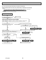
8-1-3. DC Fan motor (fan motor/indoor controller circuit board)
Check method of DC fan motor (fan motor/indoor controller circuit board)
Notes
· High voltage is applied to the connecter (CNMF) for the fan motor. Pay attention to the service.
· Do not pull out the connector (CNMF) for the motor with the power supply on.
(It causes trouble of the indoor controller circuit board and fan motor.)
Self check
Symptom : The indoor fan cannot turn around.
Wiring contact check
Contact of fan motor connector (CNMF)
Is there contact failure?
Wiring recovery
Yes
No
Power supply check (Remove the connector (CNMF))
Measure the voltage in the indoor controller circuit board.
TEST POINT : VDC (between 1 (+) and 4 (-) of the fan connector): VDC DC310~340V
TEST POINT : VCC (between 5 (+) and 4 (-) of the fan connector): VCC DC15V
Is the voltage normal?
Indoor controller board fuse check
No
No
Is the fuse normal?
Replace the fuse
Yes
OK
Check the operation
Yes
Sensor signal check
Measure the voltage between CNMF and
DC 0V
and DC 5V in the door controller circuit board.
No
Does the voltage repeat
DC 0V and DC 15V?
NG
Replace indoor controller board.
OK
Check the operation
END
NG
Replace the fan motor
Yes
Replace indoor
controller board
Replace the fan motor
OK
OK
Check the operation
NG
Replace the fan motor.
OCH449A
END
Check the operation
NG
Replace indoor controller board.
24
END
END
8-2. FUNCTION OF DIP SWITCH
Switch Pole
SW1
Function
setting
The black square (
Operation by switch
Function
ON
OFF
Effective
timing
1
Thermistor <Room temperature
detection> position
Built-in remote controller
Indoor unit
2
Filter clogging detection
Provided
Not provided
3
Filter cleaning
2,500 hr
100 hr
4
Fresh air intake
Effective
Not effective
5
Switching remote
display
Indicating fan operation
Thermo ON signal display ON/OFF
6
Humidifier control
Always operated while the heat in ON *1 Operated depends on the condition *2 suspension
7
Low *3
8
Airflow set in case of
Heat thermo OFF at
heating mode
9
Auto restart function
Effective
Not effective
Power ON/OFF by breaker
Effective
Not effective
10
Extra low
Setting air flow
*3
) indicates a switch position.
Remarks
Address board
<Initial setting>
ON
OFF
Under
1 2 3 4 5 6 7 8 9 10
Note :
*1 Fan operation at heating
mode
*2 Thermo ON operation at
heating mode
*3
*3
SW1-7
OFF
ON
OFF
ON
Depends on SW1-7
SW1-8
OFF
OFF
ON
ON
Extra low
Low
Setting airflow
Stop
Indoor controller board
Capacity
SW2
Capacity
code 1~6
setting
SW 2
ON
OFF
P40
ON
OFF
P100
SW3
Function
setting
Capacity
P63
1 2 3 4 5 6
P125
1 2 3 4 5 6
Set while the unit is off.
SW 2
ON
OFF
ON
OFF
Before
power
supply
ON
1 2 3 4 5 6
Heat pump/Cooling only
Cooling only
Heat pump
2
Louver
Available
Not available
3
Vane
Available
Not available
4
Vane swing function in heating
Available
(wave-flow)
Not available
5
Vane horizontal angle
Second setting *4
First setting *4
6
Vane cooling limit
angle setting
Horizontal
Setting A,B,C,D
7
Effective
Not effective
8
Changing the opening of
linear expansion valve
4-deg up
(Heating mode)
Not effective
Effective
9
Superheat setting temperature *5
—
—
10
Sub cool setting temperature *5
—
—
When replacing the indoor controller board, make sure to set the switch to the
initial setting, which is shown below.
ON
OFF
1 2 3 4 5
Indoor controller board
Set while the unit is off.
ON
OFF
Vane setting
Set up
Set up
OCH449A
Initial setting Setting
Standard
Less draft *
●
1 2 3 4 5 6 7 8 9 10
Under
*5 Please do not change
suspension
SW3-9 and SW3-10.
See 6. WIRING DIAGRAM.
*6 Each angle can be used
only 1 hour when fan speed
setting Low and Middle 1,2
Indoor controller board
Before
power
supply
ON
Vane position
Standard
Upward position than the standard
25
<Initial setting>
Note :
*4 SW3-5
Note : *4 SW3-5
SW3-5
OFF
ON
Set for each capacity.
1 2 3 4 5 6
1
SW4
Model 1~5
Selection
<Initial setting>
The black square (
Switch Pole
Operation by switch
SWA
(High ceiling)
Ceiling
(Standard)
height
selector 1~3 (Silent)
* Ceiling height can be changed depending
on SWA setting.
3
2
SWA
1
Silent
2.5m
2.6m
P40, P63
P100, P125
Address board
<Initial setting>
BCDE
F01
How to set branch number SW14 (Series R2 only)
Match the indoor unit’s refrigerant pipe with the BC
contoller’s end connection number
Remain other than series R2 at "0".
SW11
Before
power
supply
ON
90 1
78
90 1
Address board
<Initial setting>
SW14
F01
789A
789A
• To operate each indoor unit by each remote controller when installed 2 indoor
units or more are near, Pair No. setting is necessary.
Pair No. setting is available with the 4 patterns (Setting patters A to D).
Make setting for J41, J42 of indoor controller board and the Pair No. of
wireless remote controller.
• You may not set it when operating it by 1 remote controller.
Setting for indoor unit
Jumper wire J41, J42 on the indoor controller board are cut according to
the table below.
Wireless remote controller pair number:
Setting operation
1. Press the SET button (using a pointed implement). Check that the
remote controller's display has stopped before continuing.
MODEL SELECT flashes, and the model No. (3 digits) appears (steadily-lit).
2. Press the MINUTE button twice. The pair number appears flashing.
3. Press the temperature
buttons to select the pair number to set.
4. Press the SET button (using a pointed implement). The set pair number is
displayed (steadily-lit) for 3 seconds, then disappears.
Setting pattern
Indoor controller
Jumper wire
45 6
BCDE
SW14
SW12
78
78
78
1
23
Rotary switch
10
How to set address
Example : If address is "3", remain SW12
(for over 10) at "0", and match SW11 (for 1 to 9)
with "3".
45 6
90 1
Address can be set while the
unit is stopped.
<Initial setting>
23
Rotary switch
Under
operation
or
suspension
3
2
1
23
Jumper
Address board
<Initial setting>
45 6
SW11
23
90 1
45 6
J41, J42
Wireless
remote
controller
Pair No.
SW12
23
SW14
Branch
No.
setting
High ceiling
3.5m
4.2m
Remarks
Address board
23
SW12
10ths digit
address
setting
(Standard)
45 6
SW11
1s digit
address
setting
2
45 6
SWC
Option
selector
Standard
2.7m
3.0m
* In this model it is not necessary to
change SWC to
.
(Option)
) indicates a switch position.
Effective
timing
<Initial setting>
Pattern A
Pair No.
MODEL SELECT
MODE
FAN
AUTO STOP
VANE
AUTO START
CHECK LOUVER
h
min
TEST RUN
SET
Temperature
button
TEMP
ON/OFF
Under
operation
or
suspension
Model No.
RESET
Minute
button
CLOCK
SET button
Pair No. of wireless
remote controller *
SWE
Test run
for
Drain
pump
(Option)
Connector
J41
J42
A
—
—
0
Factory setting
B
Cut
—
1
—
C
—
Cut
2
—
D
Cut
Cut
3
—
* Pair No.4-9 of wireless remote controller is setting pattern D.
Drain pump and fan are activated simultaneously after the connector
SWE is set to ON and turn on the power.
SWE
OFF
SWE
ON
OFF
SWE
Under
operation
ON
OFF
The connector SWE is set to OFF after test run.
OCH449A
<Initial setting>
26
ON
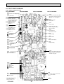
8-3. TEST POINT DIAGRAM
8-3-1. Indoor controller board
PCFY-P40VKM-E
PCFY-P63VKM-E
PCFY-P100VKM-E
PCFY-P125VKM-E
CN60
Linear expansion valve (LEV)
output
12VDC pulse output
CN3A
Connect to the terminal block (TB15)
(MA-Remote controller connecting wire)
: 8.7-13V DC (Pin (+))
CN52
Remote indicator
1-2: Status lamp 12VDC (1 : +)
Fan motor output (SW1-5 OFF)
Thermostat ON (SW1-5 ON)
1-3: Cooling/Dry status lamp
12VDC (1 : +)
1-4: Heating status lamp
12VDC (1 : +)
CNV
Vane motor output
12VDC pulse
CN32
Remote switch
CN51
Centrally control
1-2 : Control signal
12VDC pulse input (1 : +)
3-4 : Operation indicator
12VDC (3 : +)
3-5 : Malfunction indicator
12VDC (3 : +)
Jumper wire J41, J42
Pair No. setting for wireless
remote controller
LED2
Power supply for
MA-Remote controller
CN44
SW3
Pipe temperature thermistor
: Liquid (TH22)
: Gas (TH23)
Function setting
SW4
CN4F
Model selection
Drain float switch (FS)
SWE
CN20
Test run (Drain pump)
Room temperature
thermistor (TH21)
SW2
CN27
Capacity setting
Damper signal output
12VDC ( : +)
CN90
Connect to the wireless
remote controller board
(W.B)
CN2M
LED1
Connect to the terminal block (TB5)
(M-NET transmission connecting wire)
24-30VDC (non-polar)
Main power supply
(Indoor unit : 220-240V)
CNMF
Connect to the
fan motor (MF)
: DC310~340V
: DC15V
: DC0~6V
: DC0 or DC15V
CND
CNP
Power supply for indoor controller board
: 220-240VAC
Drain pump output (DP)
: 220-240VAC
The voltage range of DC12V
in this page is between
DC11.5 V to DC 13.7 V.
OCH449A
FUSE
6.3A 250V
27
PCFY-P40VKM-ER1
PCFY-P63VKM-ER1
PCFY-P100VKM-ER1
PCFY-P125VKM-ER1
CN60
Linear expansion valve (LEV)
output
12VDC pulse output
CN3A
Connect to the terminal block (TB15)
(MA-Remote controller connecting wire)
: 8.7-13V DC (Pin (+))
CN52
Remote indicator
1-2: Status lamp 12VDC (1 : +)
Fan motor output (SW1-5 OFF)
Thermostat ON (SW1-5 ON)
1-3: Cooling/Dry status lamp
12VDC (1 : +)
1-4: Heating status lamp
12VDC (1 : +)
CNV
Vane motor output
12VDC pulse
CN32
Remote switch
CN51
Centrally control
1-2 : Control signal
12VDC pulse input (1 : +)
3-4 : Operation indicator
12VDC (3 : +)
3-5 : Malfunction indicator
12VDC (3 : +)
Jumper wire J41, J42
Pair No. setting for wireless
remote controller
LED2
Power supply for
MA-Remote controller
CN44
SW3
Pipe temperature thermistor
: Liquid (TH22)
: Gas (TH23)
Function setting
SW4
CN4F
Model selection
Drain float switch (FS)
SWE
CN20
Test run (Drain pump)
Room temperature
thermistor (TH21)
SW2
CN27
Capacity setting
Damper signal output
12VDC ( : +)
CN105
CN90
Connect to the wireless
remote controller board
(W.B)
CN2M
LED1
Connect to the terminal block (TB5)
(M-NET transmission connecting wire)
24-30VDC (non-polar)
Main power supply
(Indoor unit : 220-240V)
CNMF
Connect to the
fan motor (MF)
: DC310~340V
: DC15V
: DC0~6V
: DC0 or DC15V
CND
CNP
Power supply for indoor controller board
: 220-240VAC
Drain pump output (DP)
: 220-240VAC
The voltage range of DC12V
in this page is between
DC11.5 V to DC 13.7 V.
OCH449A
FUSE
6.3A 250V
28
8-3-2. Address board
PCFY-P40VKM-E
PCFY-P40VKM-ER1
PCFY-P63VKM-E
PCFY-P63VKM-ER1
PCFY-P100VKM-E
PCFY-P100VKM-ER1
SWA
SW1
Ceiling height
selector
Function setting
SW12
Address setting
10ths DIGIT
OCH449A
SW11
Address setting
1st DIGIT
29
SWC
Option selector
SW14
Branch No.
PCFY-P125VKM-E
PCFY-P125VKM-ER1
9
DISASSEMBLY PROCEDURE
PCFY-P40VKM-E
PCFY-P40VKM-ER1
PCFY-P63VKM-E
PCFY-P63VKM-ER1
PCFY-P100VKM-E
PCFY-P100VKM-ER1
PCFY-P125VKM-E
PCFY-P125VKM-ER1
Be careful when removing heavy parts.
(Photo: PCFY-P125VKM-E)
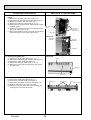
OPERATING PROCEDURE
PHOTOS & ILLUSTRATIONS
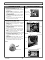
Figure 1
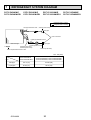
1. Removing the air intake grille
(1) Slide the air intake grille holding knobs (at 2 or 3 locations) to the rear to open the air intake grille. (See Figure 1)
(2) While the air intake grille left open, push the stoppers
on the rear hinges (at 2 or 3 locations) to pull out the air
intake grille. (See Figure 2)
Figure 2
Air intake grille
slide
Air intake grille
holding knobs
hinges
Pull out the air intake grille
Photo 1
2. Removing the indoor controller board and the electrical box
(1) Remove the air intake grille. (See Figure 1,2)
(2) Remove the screw from the beam and remove the
beam. (See Photo 1)
(3) Remove 2 screws from the electrical cover, and remove
the electrical cover.
(4) Remove 2 screws from the electrical box and pull the
electrical box downward.
Temporarily secure the electrical box using 2 hooks in
the back of electrical box.
(5) Disconnect the connectors on the indoor controller
board.
Beam
Beam fixing screws
Electrical cover
[Removing the electrical box]
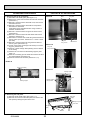
(6) Disconnect the wires from the terminal blocks and pull
out the electrical box. (See Photo 2)
Beam
fixing screw
Electrical cover
fixing screws
Photo 2
[Removing the indoor controller board]
(6) Remove the 6 supports from the indoor controller board
and remove the indoor controller board. (See Photo 3)
Electrical box
Electrical box
fixing screws
Photo 3
Room temperature
thermistor (TH21)
Indoor controller
board (I.B.)
Reactor (DCL)
Terminal blocks
(TB2),(TB5),(TB15)
OCH449A
30
OPERATING PROCEDURE
PHOTOS & ILLUSTRATIONS
3. Removing the room temperature thermistor (TH21)
(1) Remove the air intake grille. (See Figure 1, 2)
(2) Remove the screw from the beam and remove the beam.
(See Photo 1)
(3) Remove 2 screws from the electrical cover, and remove
the electrical cover.
(4) Remove 2 screws from the electrical box and pull the
electrical box downward.
Temporarily secure the electrical box using 2 hooks in
the back of electrical box.
(5) Disconnect the connector CN20 (red) from the indoor
controller board.
(6) Remove the sensor holder from the electrical box and
remove the thermistor form the holder.
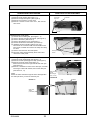
4. Removing the fan motor and right side fan
(1) Remove the air intake grille. (See Figure 1, 2)
(2) Remove the screw from the beam and remove the beam.
(See Photo 1)
(3) Remove 2 screws from the electrical cover, and remove
the electrical cover.
(4) Remove 2 screws from the electrical box and pull the
electrical box downward.
(5) Temporarily secure the electrical box using 2 hooks in
the back of electrical box.
(6) Remove 4 screws fixing fan guard of the fan motor. (2
screws : See Photo 5 / 2 screws : Upper the electrical
box)
(7) Remove 2 screws fixing fan guard of piping side and
remove the fan guard. (See Photo 6)
(8) Remove the lower casing while pressing the 4 catches of
the casing (right side of the fan motor).
(9) Loosen the 2 set screws (2 hexagon set screws) of connecting joint and slide the fan motor to the left. (See
Photo 5)
(10) Remove the motor piece (left and right, each 1 screw).
(See Photo 5)
(11) Remove the fan motor and right side fan together.
(12) Loosen the set screw (hexagon set screw) of fan and
remove the fan from the shaft. (See Photo 7, 8)
Photo 4
Casing
Room temperature
thermistor (TH21)
Electrical box
Photo 5
Set screws
Fan guard fixing screws
Fan motor
Connecting joint
Photo 6
Catch
Motor piece
fixing screws
Fan guard fixing screws
Fan guard
Photo 8
Catch
Photo 7
Hexagon set screw
OCH449A
31
Hole for driver
OPERATING PROCEDURE
PHOTOS & ILLUSTRATIONS
5. Removing the fan (3 connection)
(1) Remove the air intake grille. (See Figure 1, 2)
(2) Remove the screw from the beam and remove the beam.
(See Photo 1)
(3) Remove 2 screws from the electrical cover, and remove
the electrical cover.
(4) Remove 2 screws from the electrical box and pull the
electrical box downward.
Temporarily secure the electrical box using 2 hooks in
the back of electrical box.
(5) Remove 4 screws from the fan guard of the fan motor.
(See Photo 5)
(6) Remove 2 screws from the left side beam and remove
the beam. (See Photo 1)
(7) Remove the 3 screws from center fan guard and remove
the fan guard. (2 screws : See Photo 9 / 1 screw : Drain
pan side)
(8) Remove 2 screws from the left fan guard and remove
the fan guard. (See Photo 10)
(9) Loosen 2 set screws (2 hexagon set screws) of connecting joint. (See Photo 5)
(10) Remove 3 lower casings while pressing each 4 catches
of the casing.
(11) Remove the 4 screws from the bearing support. (See
Photo 11)
(12) Slide the connecting joint to the left and remove the fans
and shaft together. (See Photo 12)
(13) Remove the fan from the shaft. (See Photo 7, 8 )
Photo 9
Beam
Fan guard
Fan guard
fixing screws
Electrical box
Photo 10
Fan guard
fixing screws
Photo 12
Fans (3 connection)
Photo 11
Bearing support
Shaft
Shaft
Bearing support
fixing screws
Bearing support
Figure 3
6. Removing the side panel
(1) Remove the air intake grille. (See Figure 1, 2)
(2) Remove the screw from the side panel, and remove the
side panel by sliding the panel to the front.
Side panel
(Right)
Sliding the panel
to the front
Side panel
(Left)
Screw
OCH449A
32
OPERATING PROCEDURE
PHOTOS & ILLUSTRATIONS
7. Removing the vane motor
(1) Remove the air intake. (See Figure 1, 2)
(2) Remove the right side panel. (See Figure 3)
(3) Remove the connector of vane motor.
(4) Remove 2 screws of vane motor cover , then remove
vane motor.
Photo 13
Vane motor
and cover
Connector
Screws
8. Removing the under panel
(1) Remove the air intake grille. (See Figure 1, 2)
(2) Remove the left and right side panels. (See Figure 3)
(3) Remove the beam. (See Photo 1)
(4) Remove the electrical cover. (See Photo 1)
(5) Pull the electrical box downward. (See Photo 2)
(6) (Wireless remote controller receiver type only)
Disconnect the connector CNB from the PCB for wireless remote controller and remove the clamp and strap
for wires.
(7) Remove 8 screws from the under panel.
(8) Move the under panel forward by about 10mm and
remove the under panel.
Photo 14
9. Removing the drain pan
(1) Remove the air intake grille. (See Figure 1, 2)
(2) Remove the side panel (right and left). (See Figure 3)
(3) Remove the under panel. (See Photo 14)
Remove the screws of the right and left side drain pan.
(See Photo 15)
(4) Remove 2 insulation in center of the drain pan, and after
removing 2 screws with washer, remove the drain pan.
(See Photo 16, 17)
Photo 15
(Note)
Please be aware that there might be some drainage left in
the drain pan when you remove the drain pan.
Photo 17
Screw with
washer
(2 locations)
OCH449A
33
Under panel fixing
screws
Pipe cover fixing screws
Drain pan fixing
screws
(left and right
each 1 screw)
Photo 16
Drain pan
Vane
Insulations
OPERATING PROCEDURE
10. Removing the pipe thermistors / Liquid (TH22) and Gas
(TH23)
(1) Remove the air intake grille. (See Figure 1, 2)
(2) Remove the left and right side panels. (See Figure 3)
(3) Remove the under panel. (See Photo 14)
(4) Remove the drain pan. (See Photo 15, 16, 17)
(5) Disconnect the connector CN44 (white) from the indoor
controller board.
(6) Remove 6 screws from the pipe cover and remove the
pipe cover. (See Photo 15, 18)
(7) Remove the fastener for wires and remove the thermistors
(liquid and gas) from each holder. (See Photo 19)
PHOTOS & ILLUSTRATIONS
Photo 18
Pipe cover fixing
screws
Pipe cover fixing screws
(See Photo 15)
Pipe cover
Photo 19
Liquid pipe
thermistor
Gas pipe
thermistor
Fastener
Photo 20
11. Removing the guide vane
(1) Remove the intake grille. (See Figure 1, 2)
(2) Remove the side panel (right and left). (See Figure 3)
(3) Remove the under panel. (See Photo 14)
(4) Remove the drain pan. (See Photo 15, 16, 17)
(5) Remove the screw from the guide vane, then remove
the guide vane.
Screw
Drain pan
Guide vane
Photo 21
12. Removing the Auto vane
(1) Remove the intake grille. (See Figure 1, 2)
(2) Remove the right side panel. (See Figure 3)
(3) Remove the vane motor and cover. (See Photo 13)
(4) Slide the auto vane to the vane motor side.
(5) Remove 2 axes from each vane support pushing the
vane support to the vane sleeve side.
OCH449A
Vane sleeve
Vane supports
Vane
Vane motor side
34
OPERATING PROCEDURE
PHOTOS & ILLUSTRATIONS
13. Removing the heat exchanger and LEV
(1) Remove the air intake grille. (See Figure 1, 2)
(2) Remove the beam. (See Photo 1)
(3) Remove the electrical cover. (See Photo 1)
(4) Pull the electrical box downward. (See Photo 2)
(5) Disconnect the connector CN60 (white) from the indoor
controller board.
(6) Remove the left and right side panels. (See Figure 3)
(7) Remove the under panel. (See Photo 14)
(8) Remove the drain pan. (See Photo 15, 16, 17)
(9) Remove the pipe cover. (See Photo 18)
(10) Remove the pipe thermistors (TH22 and TH23) from
each holder. (See Photo 19)
(11) Remove the pipe band fixing screw and remove the
pipe band. (See Photo 22)
(12) Remove 2 screws from the heat exchanger and
remove the heat exchanger with LEV.
Photo 22
Heat exchanger
Pipe band
Pipe band fixing
screw
Photo 23
Heat exchanger
fixing screws
Heat exchanger
OCH449A
35
Vane
TM
HEAD OFFICE : TOKYO BLDG., 2-7-3, MARUNOUCHI, CHIYODA-KU TOKYO 100-8310, JAPAN
Copyright 2008 MITSUBISHI ELECTRIC CORPORATION
Distributed in Dec. 2012 No. OCH449 REVISED EDITION-A
Distributed in Dec. 2008 No. OCH449 PDF 7
Made in Japan
New publication, effective Dec. 2012
Specifications are subject to change without notice.