1
SPLIT-TYPE, HEAT PUMP AIR CONDITIONERS
June 2009
No. OCH410
REVISED EDITION-B
TECHNICAL & SERVICE MANUAL
R410A / R22
Indoor unit
[model names]
PLFY-P08NCMU-E
PLFY-P12NCMU-E
PLFY-P15NCMU-E
[Service Ref.]
Revision:
PLFY-P08NCMU-E.TH
PLFY-P08NCMU-E1.TH
PLFY-P08NCMU-ER2.TH
PLFY-P12NCMU-E.TH
PLFY-P12NCMU-E1.TH
PLFY-P12NCMU-ER2.TH
PLFY-P15NCMU-E.TH
PLFY-P15NCMU-E1.TH
PLFY-P15NCMU-ER2.TH
• PLFY-P08/12/15NCMUER2.TH are added in
REVISED EDITION-B.
• Some descriptions have
been modified.
• Please void OCH410
REVISED EDITION-A.
NOTE:
• This manual describes
only service data of the
indoor units.
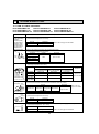
CONTENTS
1. TECHNICAL CHANGES........................................... 2
2. FEATURES................................................................ 3
3. PART NAMES AND FUNCTIONS.............................4
4. SPECIFICATIONS..................................................... 6
5. 4-WAY AIR FLOW SYSTEM......................................9
6. OUTLINES AND DIMENSIONS...............................11
7. WIRING DIAGRAM..................................................12
8. REFRIGERANT SYSTEM DIAGRAM........................ 14
9. MICROPROCESSOR CONTROL........................... 15
10. TROUBLESHOOTING.............................................22
11. DISASSEMBLY PROCEDURE................................ 29
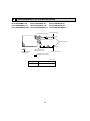
Model name
indication
INDOOR UNIT
PARTS CATALOG (OCB410)
1
TECHNICAL CHANGES
PLFY-P08NCMU-E1.TH
PLFY-P12NCMU-E1.TH
PLFY-P15NCMU-E1.TH
PLFY-P08NCMU-ER2.TH
PLFY-P12NCMU-ER2.TH
PLFY-P15NCMU-ER2.TH
• The following functions of CONTROLLER BOARD (C.B) have been changed.
* Initial setting of auto restart function
Not effective → effective (SW1-9 OFF → ON)
* External heating control change
PLFY-P08NCMU-E.TH
PLFY-P12NCMU-E.TH
PLFY-P15NCMU-E.TH
PLFY-P08NCMU-E1.TH
PLFY-P12NCMU-E1.TH
PLFY-P15NCMU-E1.TH
• PANEL has been changed.
SLP-15AAU (White : 0.70Y 8.59/0.97) → SLP-15AAUW (Pure white : 6.4Y 8.9/0.4)
2
2
FEATURES
Models
PLFY-P08NCMU-E
PLFY-P12NCMU-E
PLFY-P15NCMU-E
Cooling capacity / Heating capacity
8,000 / 9,000 Btu/h
12,000 / 13,500 Btu/h
15,000 / 17,000 Btu/h
Indoor Unit
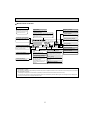
1. PERFECT PANEL SIZE
The brand new 22-7/16 inch PLFY-P08/12/15NCMU-E models are slim, attractive, yet poweful units.
PLFY-P08/12/15NCMU-E’s size and shape, which perfectly match 2-by-2 ceilings, and its lighter weight of 34 lbs
(PLFY-P08NCMU-E) make installation even easier and more convenient.
2. 29 dB WHISPER-QUIET OPERATION (PLFY-P08NCMU-E)
Ideal for cafés, bars, restaurants, and shops. Give all your customers the comfortable environment they deserve.
3. 2,500 HOUR LONG LIFE FILTER
Greatly reduces the frequency the filter needs to be replaced, making maintenance all the easier.
4. FRESH AIR INTAKE
Provides indoor air of the highest quality.
5. SMUDGE-FREE AIRFLOW
Reduces annoying drafts and smudging.
6. SLIM UNIT BODY FOR EASY INSTALLATION
The 22-7/16 inch slim body and octagonal shape, which make the distance between bolts only 16-17/32 inch, help installation easy and maintenance trouble-free.
Unit : inch
T-bar
22-11/16
23-5/8
9-1/4
22-7/16
Unit 22-7/16
8-3/16
16-17/32
20-7/8
Suspension bolt pitch
Ceiling surface
3
3
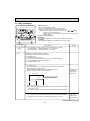
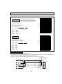
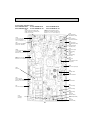
PART NAMES AND FUNCTIONS
Indoor (Main) Unit
Filter
Removes dust and pollutants
from return air.
Horizontal Air Outlet
Sets horizontal airflow automatically
during cooling or dehumidifying.
Grille
Auto Air Swing Vane
Disperses airflow up and
down and adjusts the angle
of airflow direction.
Air Intake
Returns air from room.
Wired remote controller
Once the controllers are set, the same operation mode can be repeated by simply pressing the ON/OFF button.
ON/OFF button
Temperature setting buttons
Down
Fan Speed button
Up
Timer Menu button
(Monitor/Set button)
Filter
button
(<Enter> button)
Mode button (Return button)
TEMP.
ON/OFF
Set Time buttons
Check button (Clear button)
Back
Ahead
Timer On/Off button
(Set Day button)
Test Run button
MENU
BACK
PAR-21MAA
MONITOR/SET
ON/OFF
FILTER
DAY
CHECK TEST
OPERATION
CLOCK
Airflow Up/Down button
CLEAR
Louver button
(
Operation button)
To return operation
number
Opening the
lid
Ventilation button
( Operation button)
Built-in temperature sensor
4
To go to next operation
number
Wired remote controller
Display Section
For purposes of this explanation,
all parts of the display are shown
as lit. During actual operation, only
the relevant items will be lit.
Day-of-Week
“Sensor” indication
Shows the current day of the week.
Displayed when the remote controller
sensor is used.
Time/Timer Display
Shows the current time, unless the simple or Auto Off
timer is set.
If the simple or Auto Off timer is set, the time to be
switched off is shown.
“Locked” indicator
Indicates that remote controller buttons have been locked.
Identifies the current operation
“Clean The Filter” indicator
Shows the operating mode, etc.
*Multilanguage display is available.
To be displayed on when it is time to
clean the filter.
TIME SUN MON TUE WED THU FRI SAT
TIMER
Hr
ON
AFTER
AFTER OFF
ERROR CODE
“Centrally Controlled” indicator
Indicates that operation from the
remote controller has been prohibited by a master controller.
FUNCTION
FILTER
°F°C
°F°C
WEEKLY
SIMPLE
AUTO OFF
ONLY1Hr.
Timer indicators
The indicator comes on if the corresponding timer is set.
Fan Speed indicator
Shows the selected fan speed.
“Timer is Off” indicator
Indicates that the timer is off.
Up/Down Air Direction indicator
Shows the direction of the
outcoming airflow.
“One Hour Only” indicator
Temperature Setting
Shows the target temperature.
Displayed if the airflow is set to
low or downward during COOL
or DRY mode. (Operation varies
according to model.)
The indicator goes off in one hour,
when the airflow direction also
changes.
Room Temperature display
Shows the room temperature. The room
temperature display range is 46~102°F.
The display blinks if the temperature
is less than 46°F or 102°F or more.
Ventilation indicator
Appears when the unit is running in
Ventilation mode.
Louver display
Indicates the action of the swing louver.
Does not appear if the louver is not
running.
(Power On indicator)
Indicates that the power is on.
Note:
● “PLEASE WAIT” message
This message is displayed for approximately 3 minutes when power is supplied to the indoor unit or when the unit is recovering from a power failure.
● “NOT AVAILABLE” message
This message is displayed if an invalid button is pressed (to operate a function that the indoor unit does not have).
If a single remote controller is used to operate multiple indoor units simultaneously that are different types, this message will not be displayed as
far as any of the indoor units is equipped with the function.
5
4
SPECIFICATIONS
4-1. SPECIFICATIONS
PLFY-P08NCMU-E.TH
PLFY-P08NCMU-E1.TH
PLFY-P08NCMU-ER2.TH
Item
PLFY-P12NCMU-E.TH
PLFY-P12NCMU-E1.TH
PLFY-P12NCMU-ER2.TH
PLFY-P15NCMU-E.TH
PLFY-P15NCMU-E1.TH
PLFY-P15NCMU-ER2.TH
V·Hz
Btu/h
8,000
12,000
15,000
Heating capacity
Btu/h
9,000
13,500
17,000
Cooling
kW
0.05
0.06
0.06
Heating
kW
0.05
0.06
0.06
Cooling
A
0.23
0.28
0.28
Heating
A
0.23
0.28
0.28
Electric characteristic
Power
Cooling capacity
Input
Current
Exterior
(munsell symbol)
Dimensions
—
Single phase 208/230V 60Hz
Unit : Galvanized sheets with gray heat insulation
Grilles : ABS resin
Munsell<0.7Y 8.59/0.97>(PLFY-P·NCMU-E.TH) / <6.4Y 8.9/0.4>(PLFY-P·NCMU-E1/ER2.TH)
Height
in
8-3/16<25/32>
Width
in
22-7/16<25-19/32>
Depth
in
22-7/16<25-19/32>
Cross fin
—
Turbo fan × 1
Air flow
DRY
CFM
280-320-350
3
WET
CFM
250-290-320
F
n
—
Fan × No.
a
Heat exchanger
320-350-390
290-320-350
External
static pressure
Fan motor
output
kW
Insulator
—
Polyethylene sheet
Air filter
—
PP honey comb fabric
in
1/2"
Pipe
dimensions
Gas
side
Liquid
side
Pa
0
0.015
0.020
in
1/4"
Field drain pipe size
in
O.D1-1/4"
Noise level 3
dB
29-32-38
Product weight
lb
34<7>
31-35-40
30-34-39
37<7>
Note 1. Rating conditions
Cooling :Indoor : D.B. 80°F W.B. 67°F
outdoor :D.B. 95°F W.B. 75°F
Heating :
Indoor : D.B. 70°F
outdoor :D.B. 47°F W.B. 43°F
Note 2. The number indicated in < > is for the grille.
W 3. Air flow and the noise level are indicated as Low - Medium - High.
6
4-2. NOISE CRITERION CURVES
PLFY-P08NCMU-E.TH
PLFY-P08NCMU-E1.TH
PLFY-P08NCMU-ER2.TH
NOTCH SPL(dB)
High
38
Medium
32
Low
29
LINE
PLFY-P12NCMU-E.TH
PLFY-P12NCMU-E1.TH
PLFY-P12NCMU-ER2.TH
70
NC-70
60
NC-60
50
NC-50
40
NC-40
30
NC-30
APPROXIMATE
THRESHOLD OF
HEARING FOR
CONTINUOUS
NOISE
63
125
NC-20
250
500
1000
2000
4000
OCTAVE BAND SOUND PRESSURE LEVEL, dB (0 dB = 0.0002 μbar)
OCTAVE BAND SOUND PRESSURE LEVEL, dB (0 dB = 0.0002 μbar)
80
10
80
70
60
NC-60
50
NC-50
40
NC-40
30
NC-30
20
10
8000
NC-70
APPROXIMATE
THRESHOLD OF
HEARING FOR
CONTINUOUS
NOISE
63
PLFY-P15NCMU-E.TH
PLFY-P15NCMU-E1.TH
PLFY-P15NCMU-ER2.TH
125
NC-20
250
500
1000
2000
4000
8000
BAND CENTER FREQUENCIES, Hz
BAND CENTER FREQUENCIES, Hz
NOTCH SPL(dB)
High
40
Medium
35
Low
31
LINE
UNIT
90
OCTAVE BAND SOUND PRESSURE LEVEL, dB (0 dB = 0.0002 μbar)
LINE
90
90
20
NOTCH SPL(dB)
High
39
Medium
34
Low
30
CEILING
80
70
NC-70
60
NC-60
5ft
50
NC-50
MICROPHONE
40
NC-40
30
NC-30
20
10
APPROXIMATE
THRESHOLD OF
HEARING FOR
CONTINUOUS
NOISE
63
125
NC-20
250
500
1000
2000
4000
8000
BAND CENTER FREQUENCIES, Hz
7
NOTE: The sound level is measured in an anechoic
room where echoes are few, when compressor stops. The sound may be bigger than the
indicated level in actual use due to surrounding echoes. The sound level can be higher by
about 2 dB than the indicated level during cooling and heating operation.
4-3. ELECTRICAL PARTS SPECIFICATIONS
Model
Symbol
Parts name
Thermistor
(Room temperature
detection)
Thermistor
(Pipe temperature
detection/ Liquid)
Thermistor
(Pipe temperature
detection/ Gas)
Fuse
(Indoor controller board)
PLFY-P08NCMU-E.TH
PLFY-P08NCMU-E1.TH
PLFY-P08NCMU-ER2.TH
PLFY-P12NCMU-E.TH
PLFY-P12NCMU-E1.TH
PLFY-P12NCMU-ER2.TH
PLFY-P15NCMU-E.TH
PLFY-P15NCMU-E1.TH
PLFY-P15NCMU-ER2.TH
TH21
Resistance 30F/15.8k, 50F/9.6k, 70F/6.0k, 80F/4.8k, 90F/3.9k, 100F/3.2k
TH22
Resistance 30F/15.8k, 50F/9.6k, 70F/6.0k, 80F/4.8k, 90F/3.9k, 100F/3.2k
TH23
Resistance 30F/15.8k, 50F/9.6k, 70F/6.0k, 80F/4.8k, 90F/3.9k, 100F/3.2k
FUSE
250V 6.3A
6-pole OUTPUT 15W
PK6N15-LA
6-pole OUTPUT 20W
PK6N20-LA
6-pole OUTPUT 20W
PK6N21-LA
Fan motor
(with Thermal fuse)
MF
Fan motor capacitor
C1
1.5 × 440V
Vane motor
MV
MSBPC20M13
DC12V 300/phase
Drain pump
DP
PLD-12230ME-1
INPUT 12/10.8W 241/Hr
Drain sensor
DS
Thermistor resistance 30F/6.3k, 50F/3.9k, 70F/2.5k, 80F/2.0k, 90F/1.6k, 100F/1.3k
Linear expansion valve
[coil]
LEV
DC12V Stepping motor drive, Port dimension :3.2 (0~2000pulse)
EDM-40YGME
Electric heater
(Condensation proof)
H2
240V 15W
Power supply terminal
block
TB2
(L1, L2,GR) Rated to 330V 30A +
Transmission terminal
block
TB5
(M1, M2, S) Rated to 250V 20A +
MA remote controller
terminal block
TB15
(1, 2) Rated to 250V 10A +
Thermal fuse
+Note: Refer to WIRING DIAGRAM for the supplied voltage.
8
OFF 284F $ 36F
5
4-WAY AIR FLOW SYSTEM
5-1. FRESH AIR INTAKE (Location for installation)
At the time of installation, use the duct holes (cut out) located at the positions shown in following diagram, as and when required.
Fresh air intake hole diagram
Fresh air intake
3 - W1/8
Burring hole
W3-15/16
Burring hole pitch
120"
120"
4-21/32
(Unit : inch)
W2-7/8
(Cut out hole)
Ceiling surface
Refrigerant pipe
Electrical Box
Drain pipe
5-2. FRESH AIR INTAKE AMOUNT & STATIC PRESSURE CHARACTERISTICS
PLFY-P08NCMU-E(1).TH
PLFY-P12NCMU-E(1).TH
PLFY-P15NCMU-E(1).TH
PLFY-P08NCMU-ER2.TH PLFY-P12NCMU-ER2.TH PLFY-P15NCMU-ER2.TH
Taking air into the unit
Curve in the
left graphs
1
100
A
0
C
Air flow : Q [CFM]
120
Duct characteristics
at site
B
Static pressure : P [in. W.G.%10-2]
20
20
40
60
80
0
How to read curves
Q
-20
2
C
A
-40
E
-60
Q
-80
-100
D
3
5-3. OPERATION IN CONJUNCTION
WITH DUCT FAN (BOOSTER FAN)
A
-120
NOTE: Fresh air intake amount should be 20% or less of
whole air amount to prevent dew dripping.
Q
Qa
CN51
on
indoor unit
board
• Whenever the indoor unit is operating, the duct
fun also operates.
(1) Connect the optional multiple remote controller adapter (PAC-SA88HA-E) to the connector
CN51 on the indoor controller board.
(2) Drive the relay after connecting the 12V DC
relay between the Yellow and Orange connector wires.
(*) Use a relay of 1W or smaller.
MB: Electromagnetic switch power relay for duct
fan.
X: Auxiliary relay (For DC 12V, coil rating : 1.0W
or below)
Q…Designed amount of fresh air intake
<CFM>
A…Static pressure loss of fresh air
intake duct system with air flow
amount Q
<in. W.G.o10-2>
B…Forced static pressure at air conditioner inlet with air flow amount Q
<in. W.G.o10-2>
C…Static pressure of booster fan with
air flow amount Q <in. W.G.o10-2>
D … Static pressure loss increase
amount of fresh air intake duct system for air flow amount Q
<in. W.G.o10-2>
…
E Static pressure of indoor unit with
air flow amount Q <in. W.G.o10-2>
Qa…Estimated amount of fresh air
intake without D
<CFM>
5
Green
Be sure to secure insulation
material by tape, etc.
~
Yellow
Indoor unit side
MB
Orange
1
Connector (5P)
Red
Brown
Multiple remote
controller adapter
PAC-SA88HA-E
Installation at site
Be sure to secure insulation
material by tape, etc.
Indoor controller board
CN51
Multiple remote
controller adapter
PAC-SA88HA-E
CN51
9
Distance between indoor
controller board and relay
must be within 33ft.
5-4. FIXING HORIZONTAL VANE
Horizontal vane of each air outlet can be fixed according to the environment where it is installed.
Setting procedure
1) Turn off a main power supply (Turn off a breaker).
2) Disconnect the vane motor connector of the direction of the arrow with pressing the unlocking button as shown in figure
below.
Insulate the disconnected connector with the plastic tape.
Vane motor
Vane motor
Connector
Unlocking button
Horizontal vane
3) Set a vertical vane of the air outlet, which is to be fixed by the hand slowly within the range in the table below.
Measured standard position of the grille
Horizontal vane
< Specified range >
Up/down airflow
direction
Horizontal 30°
Downward 45°
Downward 55°
Downward 70°
A
21 mm
13/16 inch
25 mm
31/32 inch
28 mm
1-3/32 inch
30 mm
1-3/16 inch
· The vanes can be set between 21mm, 13/16 inch and 30 mm, 1-3/16 inch.
Caution:
Do not set the up/down vanes passed the specified range. Condensation could form and drop from the ceiling,
or the unit could malfunction.
10
6
OUTLINES AND DIMENSIONS
PLFY-P12NCMU-E.TH
PLFY-P12NCMU-E1.TH
PLFY-P12NCMU-ER2.TH
Detail drawing of fresh air intake
Fresh air
intake
20-7/8(530)
22-7/16(570)
13-3/16(335)
16-17/32(420)
Suspension bolt pitch
1-7/32(31)
22-11/16~24-13/32(576~620)
22-7/16(570)
Ceiling surface
3-7/16(87)
2-7/32(56)
19/32~1-15/32(15~37)
22-11/16~24-13/32(576~620) Ceiling hole
7-15/16(202)
Drain pipe
VP-25 connection
(O.D.:1-1/4(:32))
Suspension bolt M10 or W3/8
9-1/16(230)
2
8-3/16(208)
9-1/4(235)
1-7/8(48)
Ceiling surface
1-1/16
Grille
+3/16 (27 +5)
0
0
25/32(20)
1-1/2~2-9/32(38~58)
3-21/32(93)
7-19/32(193)
1
Terminal block
Wiring entry
7-5/32(182)
2-1/14(57)
:2-7/8(:73.4)
Cut out hole
13-27/32(352)
13-3/16(335)
21/32(17)
2-19/32(66)
120
19/32~1-15/32(15~37)
Suspension bolt pitch
19/32~1-15/32(15~37)
Unit : inch(mm)
Models
PLFY-P08NCMU-E(1).TH
PLFY-P08NCMU-ER2.TH
PLFY-P12NCMU-E(1).TH
PLFY-P12NCMU-ER2.TH
PLFY-P15NCMU-E(1).TH
PLFY-P15NCMU-ER2.TH
Suspension bolt lower edge
1-3/8(35)
25-19/32(650)
11-27/32(301)
Air outlet hole
Brand label
2-5/32(55)
Grille
V/M
Drain hole
V/M
Auto vane
14-27/32(377)
Air intake hole
11-27/32(301)
Air outlet hole
25-19/32(650)
1(25)
3-:1/8(:2.8)
Burring hole
12
0
Ceiling hole
:3-15/16(:100)
7-27/32(199)
4-3/4(121)
PLFY-P15NCMU-E.TH Unit : inch(mm)
PLFY-P15NCMU-E1.TH
PLFY-P15NCMU-ER2.TH
4-21/32(118)
19/32~1-15/32(15~37)
PLFY-P08NCMU-E.TH
PLFY-P08NCMU-E1.TH
PLFY-P08NCMU-ER2.TH
V/M
V/M
Air intake grille
Vane motor
14-27/32(377)
Air intake hole
1-3/8(35)
2-5/32(55)
11
1
Refrigerant pipe
(1/4 (6.35) dia.)
flared connection
2
Refrigerant pipe
(1/2 (12.7) dia.)
flared connection
7
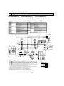
WIRING DIAGRAM
PLFY-P08NCMU-E.TH
PLFY-P08NCMU-E1.TH
PLFY-P12NCMU-E.TH
PLFY-P12NCMU-E1.TH
[LEGEND]
SYMBOL
NAME
INDOOR CONTROLLER BOARD
I.B
CN32 CONNECTOR REMOTE SWITCH
CN41
HA TERMINAL-A
CN51
CENTRALLY CONTROL
CN52
REMOTE INDICATION
FUSE FUSE (6.3A/250V)
SW1
SWITCH
MODE SELECTION
CAPACITY CODE
SW2
MODE SELECTION
SW3
MODEL SELECTION
SW4
SW11
ADDRESS SETTING 1ST DIGIT
SW12
ADDRESS SETTING 2ND DIGIT
SW14
CONNECTION No.
X1
AUX. RELAY DRAIN PUMP/DEW PREVENTION HEATER
X4
FAN MOTOR (LL)
X5
FAN MOTOR (Lo)
X6
FAN MOTOR (Hi)
X7
FAN MOTOR (Me)
ZNR
VARISTOR
PLFY-P15NCMU-E.TH
PLFY-P15NCMU-E1.TH
SYMBOL
NAME
CAPACITOR (FAN MOTOR)
C1
DRAIN PUMP
DP
DRAIN SENSOR
DS
DEW PREVENTION HEATER
H2
LINEAR EXPANSION VALVE
LEV
FAN MOTOR (WITH THERMAL FUSE)
MF
VANE MOTOR
MV
POWER SUPPLY
TB2
TERMINAL
BLOCK
TRANSMISSION
TB5
MA-REMOTE CONTROLLER
TB15
THERMISTOR ROOM TEMPERATURE DETECTION
TH21
(32F/15kΩ77F/5.4kΩ)
PIPE TEMPERATURE DETECTION/LIQUID
TH22
(32F/15kΩ77F/5.4kΩ)
PIPE TEMPERATURE DETECTION/GAS
TH23
(32F/15kΩ 77F/5.4kΩ)
INDOOR POWER BOARD
P.B
TO NEXT INDOOR UNIT
RED
TB2
BLU
GRN/YLW
FUSE(15A)
AC208-230V
CNSK(RED)
YLW
YLW
1 3 5 7 9
GRILLE
WHT
(FAN)
FAN
1 3
ORN
(POWER)
CND
1 3
RED
(D•HEATER)
CNC
1 3
BLU
(D•U•M)
CNP
3 1
FUSE
RED
(POWER
BORD)
CNDK
WHT
(POWER
BORD)
CN2D
I.B
2
1
POWER SUPPLY
~/N 208-230V 60Hz
WHT
RED
RED
BLK
YLW
BRN
WHT
BLU
C1
BREAKER
(15A)
DC13.1V
CN2S(WHT)
TRANS
3
2
1
1 2
ORN
BLK
WHT
LED1
MV 5
MV 5
5
0N
0FF
X1
X7
SW1
WHT
HA
CN41
WHT
(CENTRALLY
CONTROL)
CN51
4 3 2 1
5 4 3 2 1
1 2 3 4 5 6 7 8 9 10
SW2
SW3
1 2 3 4 5 6 1 2 3 4 5 6 7 8 9 10
0N
0FF
SW4
12345
GRN
(REMOTE
INDICATION)
CN52
5 4 3 2 1
WHT
(LEV)
CN60
WHT
(DRAIN)
CN31
6 5 4 3 2 1
3 2 1
0
6 5 4 3 2 1
CONNECTION
No.
See Fig.1
2 1
S(SHIELD)
SW12
SW11
0
0
O
3RD
DIGIT
2ND
DIGIT
RED
(INTAKE)
CN20
1ST
DIGIT
WHT
(LIQUID)
CN21
BLK
(GAS)
CN29
2 1
2 1
2 1
TH21
TH22
TH23
6
5
LEV
DS
LED on indoor controller board for service
Mark
Meaning
LED1
Main power supply
Main power supply(Indoor unit:208-230V) power on → Lamp is lit.
Function
LED2
Power supply for
MA-Remote controller
Power supply for MA-Remote controller on → Lamp is lit.
Notes:
1. At servicing for outdoor unit, always follow the wiring diagram of outdoor unit.
2. In case of using MA-Remote controller, please connect to TB15. (Remote controller wire is non-polar.)
3. In case of using M-NET, please connect to TB5. (Transmisson wire is non-polar.)
4. Symbol[S] of TB5 is the shield wire connection.
5. Symbols used in wiring diagram above are,
:terminal block,
:connecter.
6. The setting of the SW2 dip switch differs in the capacity. For the detail, refer to Fig.1.
7. Use copper supply wire.
12
<Fig.1>
MODELS
SW2
P08
ON
OFF
P12
ON
OFF
P15
ON
OFF
1
2
LED2
SW14
GRN
(VANE)
CN6V
M1
M2
TB15
3 1
BLU
(M-NET)
CN2M
ZNR
BLU
(REMOCON)
CN3A
X6 X5 X4
X7
RED
ORN
YLW
WHT
BLU
0N
0FF
X6 X5 X4
BRN
RED
BLU
ORN
YLW
WHT
MV
5
TB5
X1
3 2 1
MV 5
9
8
RED
10
RED
5
RED 4
7
ORN
6
YLW
3
WHT
2
BLU 1
WHT
(REMOTE SWITCH)
CN32
H2
PULL BOX
P.B
DP
2 1
MF
L1
L2
GR
123456
123456
123456
TO OUTDOOR UNIT
BC CONTROLLER
M-NET REMOTE
CONTROLLER
DC24-30V
TO MA-REMOTE
CONTROLLER
DC8.7-13V
PLFY-P08NCMU-ER2.TH
PLFY-P12NCMU-ER2.TH
PLFY-P15NCMU-ER2.TH
(RED)
(RED)
Fig.1
Notes:
1. At servicing for outdoor unit, always follow the wiring diagram of outdoor unit.
2. In case of using MA-Remote controller, please connect to TB15. (Remote controller wire is non-polar.)
3. In case of using M-NET, please connect to TB5. (Transmisson wire is non-polar.)
4. Symbol [S] of TB5 is the shield wire connection.
5. Symbols used in wiring diagram above are,
: terminal block,
:connecter.
6. The setting of the SW2 dip switch differs in the capacity. For the detail, refer to Fig.1.
7. Use copper supply wire.
LED on indoor controller board for service
Mark
LED1
(RED)
LED2
(RED)
Meaning
Function
Main power supply
Main power supply(Indoor unit:208-230V) power on → Lamp is lit.
Power supply for
MA-Remote controller
Power supply for MA-Remote controller on → Lamp is lit.
13
<Fig.1>
MODELS
SW2
P08
ON
OFF
P12
ON
OFF
P15
ON
OFF
123456
123456
123456
8
REFRIGERANT SYSTEM DIAGRAM
PLFY-P08NCMU-E.TH
PLFY-P08NCMU-E1.TH
PLFY-P08NCMU-ER2.TH
PLFY-P12NCMU-E.TH
PLFY-P12NCMU-E1.TH
PLFY-P12NCMU-ER2.TH
Gas pipe thermistor TH23
PLFY-P15NCMU-E.TH
PLFY-P15NCMU-E1.TH
PLFY-P15NCMU-ER2.TH
Strainer (#50mesh)
Gas pipe
Liquid pipe thermistor TH22
Flare connection
Heat exchanger
Room temperature
thermistor TH21
Liquid pipe
Linear expansion valve
Strainer1 (#50 mesh)
Strainer2 (#100 mesh)
Strainer (#100 mesh)
Refrigerant flow in cooling
Refrigerant flow in heating
Unit : inch
Gas pipe
1/2
Liquid pipe
1/4
14
9
MICROPROCESSOR CONTROL
INDOOR UNIT CONTROL
9-1. COOL OPERATION
TIME SUN MON TUE WED THU FRI SAT
TIMER
Hr
ON
AFTER
AFTER OFF
ERROR CODE
FUNCTION
FILTER
ûFûC
°F °C
WEEKLY
SIMPLE
AUTO OFF
ONLY1Hr.
TEMP.
MENU
BACK
PAR-21MAA
MONITOR/SET
ON/OFF
ON/OFF
FILTER
DAY
CLOCK
CHECK TEST
OPERATION
<How to operate>
1 Press POWER ON/OFF button.
2 Press the operation MODE button to display COOL.
3 Press the TEMP. button to set the desired temperature.
NOTE: The set temperature changes 1°F(2°F) when the
or
button is
pressed once. Cooling 67 to 87°F
Variable range of the set temprature depends on the remote controller
which is applied.
CLEAR
Control modes
1. Thermoregulating
function
Control details
Remarks
1-1. Thermoregulating function (Function to prevent restarting for 3 minutes)
• Room temperature
desired temperature + 2°F ···Thermo ON
• Room temperature desired temperature ···Thermo OFF
1-2. Anti-freezing control
Detected condition : When the liquid pipe temp. (TH22) is 32°F or less in 16
minutes from compressor's start up, anti-freezing control
starts and the thermo OFF.
Released condition : The timer which prevents reactivating is set for 3 minutes,
and anti-freezing control is cancelled when any one of the
following conditions is satisfied.
Liquid pipe temp. (TH22) turns 50°F or above.
The condition of the thermo OFF has completed by
The operation modes became mode other than COOL.
thermoregulating, etc.
The operation stopped.
2. Fan
By the remote controller setting (switch of 3 speeds)
Type
Fan speed notch
3 speeds type
[Low], [Med], [High]
Continued to the next page
15
From the preceding page
Control modes
3. Drain pump
Remarks
Control details
3-1. Drain pump control
• Always drain pump ON during the COOL and DRY mode operation.
(Regardless of the thermo ON/ OFF)
• When the operation mode has changed from the COOL or DRY to the
others (including Stop), OFF the control after the drain pump ON for 3
minutes.
Drain sensor function
• Energize drain sensor at a fixed voltage for a fixed duration. After energizing,
compare the drain sensor’s temperature to the one before energizing, and judge
whether the sensor is in the air or in the water.
Drain sensor
Indoor control
P.C. board
CN31
→
Basic control system
1
2
3
• While drain pump is turned on, repeat the following control system and judge
whether the sensor is in the air or in the water.
Timing of
energizing
drain sensor
ON
·······Repeat
OFF
Stand by for
a minute
30
sec.
Stand by for
a minute
Detect the
temperature
before
energizing
(T0)
30
sec.
Detect the
temperature
after
energizing
(T1)
Judge whether
the sensor is in
the air or in the
water.
• Drain sensor temperature rise (∆t)
• Temperature of drain sensor before current is applied (T0)
• Temperature of drain sensor after current is applied (T1)
[ ∆t = T1 – T0 ]
(up/down vane change)
(1) Initial setting : Start at COOL mode and horizontal vane.
"Only 1 Hr"
(2) Vane position : Horizontal →Downward A →Downward B →Downward C→Swing appears on the
wired remote
(3) Restriction of the downward vane setting
controller.
When setting the downward vane A, B or C in [Med] or [Low] of the fan
speed notch, the vane changes to horizontal position after 1 hour.
→
4. Vane
16
9-2. DRY OPERATION
<How to operate>
1 Press POWER ON/OFF button.
2 Press the operation MODE button to display DRY.
3 Press the TEMP. button to set the desired temperature.
NOTE: The set temperature changes 1°F(2°F) when the
or
button is
pressed once. Dry 67 to 87°F
Variable range of the set temprature depends on the remote controller
which is applied.
TIME SUN MON TUE WED THU FRI SAT
TIMER
Hr
ON
AFTER
AFTER OFF
ERROR CODE
FUNCTION
FILTER
ûFûC
°F °C
WEEKLY
SIMPLE
AUTO OFF
ONLY1Hr.
TEMP.
MENU
BACK
PAR-21MAA
MONITOR/SET
ON/OFF
ON/OFF
FILTER
DAY
CLOCK
CHECK TEST
OPERATION
CLEAR
Control modes
Remarks
Control details
1. Thermo regulating 1-1. Thermo regulating function (Function to prevent restarting for 3 minutes)
Setting the Dry thermo by the thermo regulating signal and the room
function
temperature (TH21).
Dry thermo ON Room temperature desired temperature + 2°F
Dry thermo OFF Room temperature desired temperature
Room
temperature
Dry thermo Dry thermo
ON
OFF
Thermo regulating signal Room temperature (T1) time (min) time (min)
3 min. passed since starting operation
ON
Over 64°F
OFF
T1 83°F
9
3
83°F > T1 79°F
7
3
79°F > T1 75°F
5
75°F > T1
3
3
3
3
10
Unconditional
Less than 64°F
Dry thermo OFF
1-2. Freeze prevention control
No control function
2. Fan
Indoor fan operation controll depends on the compressor conditions.
Dry thermo
Fan speed notch
ON
[Low]
OFF
Stop
Note: Remote controller setting is not acceptable.
3. Drain pump
Same control as COOL operation
Same control as COOL operation
4. Vane
(up/down vane change)
17
9-3. FAN OPERATION
<How to operate>
1 Press POWER ON/OFF button.
2 Press the operation MODE button to display FAN.
TIME SUN MON TUE WED THU FRI SAT
TIMER
Hr
ON
AFTER
AFTER OFF
ERROR CODE
FUNCTION
FILTER
ûFûC
°F °C
WEEKLY
SIMPLE
AUTO OFF
ONLY1Hr.
TEMP.
MENU
BACK
PAR-21MAA
MONITOR/SET
ON/OFF
ON/OFF
FILTER
DAY
CLOCK
CHECK TEST
OPERATION
CLEAR
Control modes
1. Fan
2. Drain pump
Control details
Set by remote controller.
Type
Fan speed notch
3 speeds type
[Low], [Med], [High]
2-1. Drain pump control
The drain pump turns ON for the specified amount of time when any of the following
conditions is met:
ON for 3 minutes after the operation mode is switched from COOL or DRY to
another operation mode (FAN).
ON for 6 minutes after the drain sensor is determined to be submerged using the
liquid level detection method given below.
ON for 6 minutes after indoor piping (liquid piping) temperature – indoor intake
temperature -18°F, AND the drain sensor input is at the short or open level.
(If condition or is still being met after the drain pump has been turned ON for 6
minutes, the drain pump is kept ON for further 6 minutes.)
2-2. Liquid level detection method
The liquid level is detected by determining whether or not the drain sensor is
submerged, based on the amount the temperature rises after self-heating the
sensor. This process is performed if any of the following conditions is met:
Drain pump is ON.
Indoor piping (liquid piping) temperature – indoor intake temperature -18°F
Indoor piping (liquid piping) temperature or indoor intake temperature is at the
short or open level temperature.
Every 1 hour after the drain pump has been switched from ON to OFF and 1
hour have passed.
3. Vane
Same as the control performed during the COOL operation, but no restriction on the
(up/down vane change) vane's downward blow setting
18
Remarks
9-4. HEAT OPERATION
<How to operate>
1 Press POWER ON/OFF button.
2 Press the operation MODE button to display HEAT.
3 Press the TEMP. button to set the desired temperature.
NOTE: The set temperature changes 1°F(2°F) when the
or
button is
pressed once. Heating 63 to 83°F
Variable range of the set temprature depends on the remote controller
which is applied.
<Display in HEAT operation>
[DEFROST]
The [DEFROST] symbol is only displayed during the defrost operation.
[STANDBY]
The [STANDBY] symbol is only displayed during hot adjust mode.
TIME SUN MON TUE WED THU FRI SAT
TIMER
Hr
ON
AFTER
AFTER OFF
ERROR CODE
FUNCTION
FILTER
ûFûC
°F °C
WEEKLY
SIMPLE
AUTO OFF
ONLY1Hr.
TEMP.
MENU
BACK
PAR-21MAA
MONITOR/SET
ON/OFF
ON/OFF
FILTER
DAY
CLOCK
CHECK TEST
OPERATION
CLEAR
Control modes
Remarks
Control details
1. Thermoregulating 1-1. Thermoregulating function (Function to prevent restarting for 3 minutes)
• Room temperature desired temperature -2°F ···Thermo ON
function
• Room temperature desired temperature ···Thermo OFF
2. Fan
Controlled by the remote controller (3-speed)
Give priority to controlled mode mentioned below.
2-1. Hot adjust mode
2-2. Residual heat exclusion mode
2-3. Thermo OFF mode (When the compressor off by the thermoregulating)
2-4. Cool air prevention mode (Defrosting mode)
2-5. Capacity increasing mode
2-1. Hot adjust mode
The fan controller becomes the hot adjust mode for the following conditions.
When starting the HEAT operation
When the thermoregulating function changes from OFF to ON.
When release the HEAT defrosting operation
Hot adjust mode +1
+1
"STAND BY" will
be displayed
during the hot
adjust mode.
Set fan speed by the remote controller
[Low]
[Extra Low]
A
B
C
A: Hot adjust mode start
B: 5 minutes have passed since the condition A or the indoor liquid pipe temperature
turned 95°F or more
C: 2 minutes have passed since the condition A (Terminating the hot adjust mode)
2-2. Residual heat exclusion mode
When the condition changes the auxiliary heater ON to OFF (thermoregulating or
operation stop, etc), the indoor fan operates in [Low] mode for 1 minute.
This control is
same for the
model without
auxiliary heater.
Continued to the next page
19
From the preceding page
Control details
Control modes
2. Fan
2-3. Thermo OFF mode
When the thermoregulating function changes to OFF, the indoor fan operates in
[Extra low].
2-4. Heat defrosting mode
The indoor fan stops.
No drain pump operation
However, when the control changes from COOL or DRY operation, the drain pump
operates for 3 minutes.
4. Vane control
(Up/down vane
change)
(1) Initial setting : OFF → HEAT···[last setting]
When changing the mode from exception of HEAT to HEAT operation
···[Downward C]
(2) Vane position :
Horizontal →Downward A →Downward B →Downward C→Swing
→
3. Drain pump
(3) Restriction of vane position
The vane is horizontally fixed for the following modes.
(The setting by the remote controller is temporarily invalidated and vane control is
set by the unit controller.)
• Thermo OFF
• Hot adjust [Extra low] mode
• Heat defrost mode
20
Remarks
9-5. AUTO OPERATION [AUTOMATIC COOL/HEAT CHANGE OVER OPERATION]
TIME SUN MON TUE WED THU FRI SAT
TIMER
Hr
ON
AFTER
AFTER OFF
ERROR CODE
ûFûC
°F °C
TEMP.
MENU
BACK
PAR-21MAA
MONITOR/SET
FUNCTION
FILTER
WEEKLY
SIMPLE
AUTO OFF
ONLY1Hr.
ON/OFF
ON/OFF
FILTER
DAY
CLOCK
CHECK TEST
OPERATION
CLEAR
<How to operate>
1 Press POWER ON/OFF button.
2 Press the operation MODE button to display AUTO.
3 Press the TEMP. button to set the desired temperature.
NOTE: The set temperature changes 1°F(2°F) when the
or
button is
pressed once. Automatic 67 to 83°F
Variable range of the set temprature depends on the remote controller
which is applied.
“AUTO” works to change the operation mode either to cooling or heating according to the room temperature.
Control details
Control modes
Remarks
1. Initial value of HEAT mode for room temperature < Desired temperature
operation mode COOL mode for room temperature Desired temperature
2. Mode change (1) HEAT mode → COOL mode
Room temperature Desired temperature + 3°F or 3 minutes has passed
(2) COOL mode → HEAT mode
Room temperature Desired temperature - 3°F or 3 minutes has passed
3. COOL mode
Same control as cool operation
4. HEAT mode
Same control as heat operation
9-6. WHEN UNIT IS STOPPED CONTROL MODE
Control modes
Control details
1. Drain pump
1-1. Drain pump control
The drain pump turns ON for the specified amount of time when any of the
following conditions is met (regardless of whether the compressor is ON or OFF)
ON for 3 minutes after the operation mode is switched from COOL or DRY to another
operation mode (HEAT mode).
ON for 6 minutes after the drain sensor is determined to be submerged using the
liquid level detection method given below.
ON for 6 minutes after indoor piping (liquid piping) temperature – indoor intake
temperature 14°F, and the drain sensor input is at the short or open level.
(If condition or is still being met after the drain pump has been turned ON for 6
minutes, the drain pump is kept ON for a further 6 minutes.)
1-2. Liquid level detection method
The liquid level is detected by determining whether or not the drain sensor is
submerged, based on the amount the temperature rises after self-heating the
sensor.
This process is performed if any of the following conditions is met:
Drain pump is ON.
Indoor piping (liquid piping) temperature – indoor intake temperature 14°F
(except during defrosting)
Indoor piping (liquid piping) temperature or indoor intake temperature is at the short
or open level temperature.
Every 1 hour after the drain pump has been switched from ON to OFF.
21
Remarks
10
TROUBLESHOOTING
10-1. HOW TO CHECK THE PARTS
PLFY-P08NCMU-E.TH
PLFY-P12NCMU-E.TH
PLFY-P08NCMU-E1.TH
PLFY-P12NCMU-E1.TH
PLFY-P08NCMU-ER2.TH PLFY-P12NCMU-ER2.TH
Parts name
PLFY-P15NCMU-E.TH
PLFY-P15NCMU-E1.TH
PLFY-P15NCMU-ER2.TH
Check points
Thermistor (TH21)
(Room temperature
detection)
Thermistor (TH22)
(Pipe temperature
detection/ Liquid)
Thermistor (TH23)
(Pipe temperature
detection/ Gas)
Disconnect the connector then measure the resistance with a tester.
(At the ambient temperature 50F~86F)
Vane motor (MV)
Measure the resistance between the terminals with a tester.
(At the ambient temperature 68F~86F)
White
Normal
Abnormal
4.3k~9.6k
Open or short
Connector
M
Normal
Abnormal
300
Open or short
Red — Yellow
Orange
Red — Blue
Red
Blue
Refer to the next page for the details.
Yellow
Red — Orange
Red — White
Fan motor (MF)
Measure the resistance between the terminals with a tester.
(Coil wiring temperature 50F~86F)
Normal
PLFY-P08NCMU-E(1) PLFY-P12NCMU-E(1) PLFY-P15NCMU-E(1)
PLFY-P08NCMU-ER2 PLFY-P12NCMU-ER2 PLFY-P15NCMU-ER2
P
WHT-BLK
BLK BLU YLW BRN RED ORN
WHT
# : Thermal fuse 284°F±36F
Linear expansion
valve (LEV) Blue
387~418
303~328
272~295
BLK-BLU
77~83
105~114
79~85
Opened or
BLU-YLW
19~21
39~42
37~40
short-circuited
YLW-RED
RED-BRN
179~193
235~254
191~206
Disconnect the connector then measure the resistance valve with a tester.
Normal
Abnormal
Brown
M
White-Red
Yellow-Brown Orange-Red
Blue-Brown
Yellow
Relay
connector
Yellow
Yellow
Normal
Abnormal
3
290
Open or short
1
2
3
Open or short
Measure the resistance between the terminals with a tester.
(At the ambient temperature 68F~86F)
1
Drain sensor (DS)
Refer to the next
page for the details.
200 $10%
White Red Orange
Drain pump (DP)
Abnormal
Measure the resistance after 3 minutes have passed since the power supply was intercepted.
(At the ambient temperature 32F~140F)
Normal
Abnormal
0.6k~6.0k
Open or short
22
Refer to the next page for the details.
<Thermistor characteristic graph>
< Thermistor for lower temperature >
50
Room temperature thermistor(TH21)
Liquid pipe temperature thermistor(TH22)
Gas pipe temperature thermistor(TH23)
Thermistor R0=15k' ± 3%
Fixed number of B=3480 ± 2%
Rt=15exp { 3480(
30_F
50_F
70_F
80_F
90_F
100_F
1
273+(t-32)/1.8
40
Resistance (k)
Thermistor for
lower temperature
1 )}
273
15.8k'
9.6k'
6.0k'
4.8k'
3.9k'
3.2k'
30
20
10
0
-20
10
Thermistor for
drain sensor
0
20
40
60
80
Temperature (°F)
100
120
< Thermistor for drain sensor >
9
8
Thermistor R0=6.0k' ±5%
Fixed number of B=3390 ± 2%
30_F
50_F
70_F
80_F
90_F
100_F
1
273+(t-32)/1.8
Resistance (k)
Rt=6exp { 3390(
7
1 )}
273
6.3k'
3.9k'
2.5k'
2.0k'
1.6k'
1.3k'
6
5
4
3
2
1
0
20
40
60
80
100
120
140 170
Temperature (°F)
Linear expansion valve
1 Operation summary of the linear expansion valve
• Linear expansion valve open/close through stepping motor after receiving the pulse signal from the indoor controller board.
• Valve position can be changed in proportion to the number of pulse signal.
<Connection between the indoor controller board and the linear expansion valve>
Controller board
DC12V
Linear expansion valve
4
M
6
5
2
1
White Red
3
Orange
Blue
Brown
6
Red
5
Drive circuit
Brown
:4
Blue
4
:4
Yellow
:3
Orange
3
:3
:2
Yellow
2
:2
:1
White
1
:1
Connector (CN60)
23
<Output pulse signal and the valve operation>
Output
Output
(Phase)
1
2
3
4
{1
ON
OFF
OFF
ON
{2
ON
ON
OFF
OFF
{3
OFF
ON
ON
OFF
{4
OFF
OFF
ON
ON
Closing a valve : 1 → 2 → 3 → 4 → 1
Opening a valve : 4 → 3 → 2 → 1 → 4
The output pulse shifts in above order.
• When linear expansion valve operation stops, all output phases
become OFF.
• At phase interruption or when phase does not shift in order, motor
does not rotate smoothly and motor will lock and vibrate.
2 Linear expansion valve operation
C
Valve position (capacity)
D
Close
Open
2000 pulse
Opening a valve
all the way
A
E
• When the switch is turned on, 2200 pulse closing valve signal will be
sent till it goes to A point in order to define the valve position.
• When the valve moves smoothly, there is no sound or vibration
occurring from the linear expansion valve; however, when the pulse
number moves from E to A or when the valve is locked, more
sound can be heard than normal situation.
• Sound can be detected by placing the ear against the screw driver
handle while putting the screw driver to the linear expansion valve.
Pulse number
B
Extra tightening (80~100pulse)
3
Troubleshooting
Symptom
Operation circuit
failure of the micro
processor
Check points
Disconnect the connector on the controller board, then connect LED for checking.
6
5
4
3
2
1
1k LED
Countermeasures
Exchange the indoor controller board at drive circuit
failure.
Pulse signal will be sent out for 10 seconds as soon as the
main switch is turned on. If there is LED with lights on or
lights off, it means the operation circuit is abnormal.
Linear expansion
valve mechanism is
locked.
Motor will idle and make ticking noise when motor is operated Exchange the linear expanwhile the linear expansion valve is locked. This ticking sound sion valve.
is the sign of the abnormality.
Short or breakage
Measure the resistance between the each coil (red-white,
Exchange the linear expanof the motor coil of
red-orange, brown-yellow, brown-blue) with a tester. It is nor- sion valve.
the linear expansion mal if the resistance is in the range of 200 i 10%
valve
Valve does not close To check the linear expansion valve, operate the indoor unit If a large amount of refrigcompletely (thermis- in fan mode and at the same time operate other indoor units erant is leaked, exchange
tor leaking).
in cooling mode, then check the pipe temperature <liquid pipe the linear expansion valve.
temperature> of the indoor unit by the outdoor multi controller board operation monitor. During fan operation, linear expansion
valve is closed completely and if there are
Thermistor
(Liquid pipe) some leaking, detecting temperature of
the thermistor will go lower. If the detected
Linear
expansion
temperature is much lower than the temvalve
perature indicated in the remote controller,
it means the valve is not closed all the
way. It is not necessary to exchange the linear expansion
valve, if the leakage is small and not making any trouble.
Wrong connection
of the connector or
contact failure
Check the color of lead wire and missing terminal of the con- Disconnect the connector
nector.
at the controller board,
then check the continuity.
24
10-2. FUNCTION OF DIP SWITCH
is the switch position.
Switch Pole
SW1
Function
Selection
Operation by switch
Function
ON
OFF
1
Thermistor <Room temperature
detection> position
Built-in remote controller
Indoor unit
2
Filter clogging detection
Provided
Not provided
3
Filter cleaning
2,500h
100h
4
Fresh air intake
Effective
Not effective
5
Remote indication switching
Thermo ON signal indication Fan output indication
6
Humidifier control
Fan operation at Heating mode
7
8
9
10
Low +1
Airflow setting during
thermo OFF in heating mode Setting air flow +1
Thermo ON operation at
heating mode
Effective
timing
Remarks
Indoor controller board
<Initial setting> +2
ON
OFF
+1
Under
suspension
SW 1-7 SW 1-8 Fan speed
Extra low +1
Depends on SW1-7
Auto restart function
Effective
Not effective
Power ON/OFF
Effective
Not effective
1 2 3 4 5 6 7 8 9 10
OFF
OFF
Extra low
ON
OFF
Low
OFF
ON
Setting air flow
ON
ON
stop
+2 SW1-9 setting
PLFY-P·NCMU-E(1) : OFF
PLFY-P·NCMU-ER2: ON
Indoor controller board
SW 2
Capacity
SW2
P08
Capacity
code 1~6
setting
P12
SW3
Function
setting
ON
OFF
ON
OFF
Capacity
SW 2
ON
OFF
P15
1 2 3 4 5 6
1 2 3 4 5 6
Heat pump / Cooling only Cooling only
2
Louver
Vane
Available
Not available
4
Vane swing function
Available
Not available
5
Vane horizontal angle
Second setting +5
First setting
6
Vane cooling limit angle setting +3 Horizontal angle
Down B, C
Effective
Not effective
Not effective
Effective
8
Heat 4degrees up
9
Superheat setting temperature +4
—
—
10
Sub cool setting temperature +4
—
—
Unit
1~5
Selection
Set while the unit is off.
Not available
Available
Indoor linear expansion
valve opening
Indoor controller board
Heat pump
3
SW4
Set for each capacity.
1 2 3 4 5 6
1
7
<Initial setting>
Before
power
supply
ON
In case of replacing the indoor controller board, make sure to set the switch to
the initial setting, which is shown below.
ON
OFF
1 2 3 4 5
25
<Initial setting>
ON
OFF
1 2 3 4 5 6 7 8 9 10
Under
Note :
suspension +3 At cooling mode, each
angle can be used only
1 hour.
+4 Do not use SW3-9, 10
as trouble might be
caused by the usage
condition.
+5 Second setting is same
as first setting
Indoor controller board
Before
power
supply
ON
Pole
Effective
timing
Operation by switch
SW11
Indoor controller board
<Initial setting>
SW14
F01
23
45 6
How to set branch numbers SW14 (Series R2 only)
Match the indoor unit’s refrigerant pipe with
the BC controller’s end connection number.
Remain other than series R2 at "0".
78
90 1
78
78
SW11
90 1
BCDE
BCDE
F01
789A
Rotary switch
78
SW14
SW12
789A
Before
power
supply
ON
45 6
Rotary switch
<Initial setting>
45 6
1
How to set addresses
Example: If address is "3", remain SW12
(for over 10) at "0", and match SW11 (for 1 to 9)
with "3".
45 6
45 6
45 6
10
23
Connection
No.
setting
90 1
23
SW14
SW11
90 1
23
10ths digit
address
setting
SW12
23
SW12
Indoor controller board
23
1s digit
address
setting
Remarks
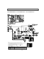
10-3. TEST POINT DIAGRAM
10-3-1. Indoor power board
PLFY-P08NCMU-E.TH
PLFY-P12NCMU-E.TH
PLFY-P08NCMU-E1.TH
PLFY-P12NCMU-E1.TH
PLFY-P08NCMU-ER2.TH PLFY-P12NCMU-ER2.TH
PLFY-P15NCMU-E.TH
PLFY-P15NCMU-E1.TH
PLFY-P15NCMU-ER2.TH
CN2S
Connect to the indoor controller board (CN2D)
Between 1 to 3 12.5-13.7V DC (Pin1 (+))
CNSK
Connect to the indoor controller board (CNDK)
Between 1 to 3 208-230V AC
26
10-3-2. Indoor controller board
PLFY-P08NCMU-E.TH
PLFY-P12NCMU-E.TH
PLFY-P08NCMU-E1.TH
PLFY-P12NCMU-E1.TH
CN2M
Connect to the terminal block (TB5)
(M-NET transmission connecting wire)
24-30V DC (non-polar)
PLFY-P15NCMU-E.TH
PLFY-P15NCMU-E1.TH
CN3A
Connect to the terminal block (TB15)
(MA-Remote controller connecting wire)
Between 1 to 3 8.7-13V DC (Pin1 (+))
CN2D
Connect to the indoor
power board (CN2S)
12.5-13.7V DC (Pin1 (+))
CN29
Pipe temperature
detection/Gas (TH23)
LED2
Power supply for
MA-Remote controller
CN21
Pipe temperature
detection/Liquid (TH22)
LED1
Main power supply
(Indoor unit : 208-230V)
CN20
Room temperature
detection (TH21)
CN31
Drain sensor (DS)
CNDK
Connect to the indoor power
board (CNSK)
Between 1 to 3 208-230V AC
SW11
Address setting
1s DIGIT
SW12
Address setting
10s DIGIT
CNP
Drain pump output (DP)
Between 1 to 3 208-230V AC
SW14
Branch No.
CN60
Linear expansion valve
output (LEV)
CN6V
Vane motor output (MV)
FUSE
6.3A 250V
CN51
Centrally control
CN52
Remote indication
CND
Power supply for
indoor controller board
Between 1 to 3 208-230V AC
SW4
Model selection
SW3
Function setting
FAN
Fan motor output (MF)
SW1
Function setting
SW2
Capacity setting
CN32
Connector
(Remote switch)
CN27
Connector
(Damper)
CN25
Connector(Humidifier)
CN24
Connector
(External heater)
27
PLFY-P08NCMU-ER2.TH PLFY-P12NCMU-ER2.TH
CN2M
Connect to the terminal block (TB5)
(M-NET transmission connecting wire)
24-30V DC (non-polar)
PLFY-P15NCMU-ER2.TH
CN3A
Connect to the terminal block (TB15)
(MA-Remote controller connecting wire)
Between 1 to 3 8.7-13V DC (Pin1 (+))
LED2
Power supply for
MA-Remote controller
CN2D
Connect to the indoor
power board (CN2S)
12.5-13.7V DC (Pin1 (+))
CN29
Pipe temperature
detection/Gas (TH23)
LED1
Main power supply
(Indoor unit : 220-240V)
CN21
Pipe temperature
detection/Liquid (TH22)
CN20
Room temperature
detection (TH21)
CNDK
Connect to the indoor power
board (CNSK)
Between 1 to 3 208-230V AC
SW11
Address setting
1s DIGIT
CN31
Drain sensor (DS)
SW12
Address setting
10ths DIGIT
CNP
Drain pump output (DP)
Between 1 to 3 208-230V AC
SW14
Branch No.
CN60
Linear expansion valve
output (LEV)
FUSE
6.3A 250V
CN6V
Vane motor output (MV)
CN90
Connect to the wireless
junction cable
CND
Power supply for
indoor controller board
Between 1 to 3 208-230V AC
CN52
Remote indication
CN51
Centrally control
FAN
Fan motor output (MF)
SW4
Model selection
SW3
Function setting
SW1
Model selection
SW2
Capacity setting
Jumper wire J41, J42
Pair No. setting for
wireless remote controller
CN27
Connector
(Damper)
CN32
Connector
(Remote switch)
28
CN25
Connector(Humidifier)
CN24
Connector
(External heater)
11
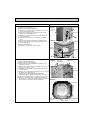
DISASSEMBLY PROCEDURE
PLFY-P08/12/15NCMU-E.TH
PLFY-P08/12/15NCMU-E1.TH
PLFY-P08/12/15NCMU-ER2.TH
OPERATING PROCEDURE
Be careful when removing heavy parts.
PHOTOS&ILLUSTRATIONS
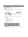
1. Removing the air intake grille
(1) Slide the knob of air intake grille to the direction of the
arrow 1 to open the air intake grille.
(2) Remove the string hook from the panel to prevent the grille
from dropping.
(3) Slide the hinge of the intake grille to the direction of the
arrow 2 and remove the air intake grille.
Figure 1
Air intake grille
Grille
Air intake grille knob
Photo 1
2. Removing the fan guard
(1) Open the air intake grille.
(2) Remove the 3 screws of fan guard.
Fan guard
Screws
Air intake grille
3. Removing the panel
(1) Remove the air intake grille. (Refer to 1)
Corner panel (See Figure 2)
(1) Remove the screw of the corner.
(2) Slide the corner panel to the direction of the arrow 3, and
remove the corner panel.
Panel (See Photo 2)
(1) Disconnect the connector that connects with the unit.
(2) Remove the 2 screws from the panel and loose other
2 screws, which are fixed to the oval hole, have different
diameter.
(3) Rotate the panel a little to remove the screws.(Slide the
panel so that the screw comes to a larger diameter of the
oval hole, which has two different diameters.)
Corner
Screw panel
Figure 2
Corner
panel
Photo 2
Screws
Connector
Screws
Panel
Photo 3
4. Removing the electrical parts
(1) Remove the 2 screws and the control box cover.
<Electrical parts in the control box>
• Indoor controller board (I.B)
• Indoor power board (P.B)
• Fan motor capacitor (C1)
• Fuse (FUSE)
• Varistor (ZNR)
• Terminal block (TB)
Fan motor
Capacitor
(C1)
Indoor
controller
board (I.B)
Indoor controller
box
29
Panel
Indoor
power
board
(P.B)
Varistor
(ZNR)
Terminal
block
(TB5)
Fuse
(FUSE)
Terminal
block
(TB15)
Terminal
block
(TB2)
OPERATING PROCEDURE
PHOTOS&ILLUSTRATIONS
5. Removing the room temperature detection (TH21)
Photo 4
(1) Remove the panel. (Refer to 3)
(2) Pull out the room temperature detection from the drain pan.
(3) Remove the 2 screws fixed to the control box cover, and
remove the control box cover.
Screw
(4) Remove the connector (CN20) from the indoor controller
board, and disconnect the room temperature detection.
Room
Connectors
Control box
Drain plug
Screw
temperature
detection
(TH21)
6. Removing the drain pan
(1) Remove the panel. (Refer to 3)
(2) Remove the room temperature detection and the 2 lead
wires held with fastener; wireless controller board relay
connector (9P red) and panel relay connector (10P white).
(3) Remove the 4 screws fixed to the drain pan, and remove
the drain pan.
(4) Remove the fan guard. (Refer to 2)
7. Removing the pipe temperature detection/liquid (TH22)
and pipe temperature detection/gas (TH23)
(1) Remove the panel. (Refer to 3)
(2) Remove the drain pan. (Refer to 6)
(3) Disconnect the liquid or gas from the holder.
(4) Remove the 3 screws fixed to the piping cover, and remove
the piping cover. (See Photo 9)
(5) Remove the 2 screws fixed to the control box cover, and
remove the control box cover.
Drain pan
Screw
Screw
Fan guard
Control box
Photo 5
LEV
Pipe temperature detection/liquid (TH22)
(6) Remove the connector (CN21) from the indoor controller
board, and disconnect the pipe temperature detection/Liquid.
Pipe temperature detection/gas (TH23)
(6) Remove the connector (CN29) from the indoor controller
board, and disconnect the pipe temperature detection/Gas
with its holder.
Thermistor
(Pipe temperature
detection/ Liquid)
(TH22)
Photo 6
8. Removing the fan motor (MF)
(1) Remove the panel. (Refer to 3)
Nut
(2) Remove the drain pan. (Refer to 6)
(3) Remove the nut and the washer from the turbo fan, and
Flat plate
remove the turbo fan.
(4) Remove the 2 screws fixed to the control box cover, and
remove the control box cover.
(5) Disconnect the connectors of the (FAN) from the indoor
Fan
controller board.
motor
(6) Remove the 3 screws fixed to the piping cover, and remove (MF)
the piping cover. (See photo 9)
(7) Remove the 6 screws fixed to the flat plate, and remove
the flat plate.
(8) Disconnect the lead wires to the direction of the fan motor,
and remove 3 nuts of the fan motor.
Screws
30
Thermistor
(Pipe temperature
detection/ Gas)
(TH23)
Screws
Lead
wires
Nuts
Screws
OPERATING PROCEDURE
PHOTOS&ILLUSTRATIONS
9. Removing the drain pump (DP) and drain sensor (DS)
(1) Remove the panel. (Refer to 3 )
(2) Remove the drain pan. (Refer to 6)
(3) Remove the 2 screws fixed to the control box cover, and
remove the control box cover.
(4) Remove the connectors of the (CNP) and the (CN31)
from the indoor controller board.
(5) Remove the 1 screw fixed to the cover, and remove the
cover.(See photo 7)
(6) Disconnect the lead wires to the direction of the drain
pump.
(7) Remove the 3 screws of the drain pump.(See photo 8)
(8) Cut the drain hose fixing band, pull out the drain hose
from the drain pump.
(9) Pull out the drain pump.
(10) Remove the drain sensor and the holder.
Photo 7
Lead wires
Control
box
Cover
Screw
Photo 8
Drain sensor (DS)
Drain pump (DP)
Drain
hose
Screws
Screw
10. Removing the heat exchanger
(1) Remove the panel. (Refer to 3 )
(2) Remove the drain pan. (Refer to 6)
(3) Remove the nut and the washer from the turbo fan, and
remove the turbo fan.
(4) Remove the 2 screws fixed to the control box cover, and
remove the control box cover.
(5) Disconnect the connectors of the (FAN) from the indoor
controller board.
(6) Remove the 3 screws fixed to the piping cover, and remove
the piping cover. (See photo 9)
(7) Remove the pipe temperature thermistor/liquid and
condenser/evaporator temperature thermistor. (Refer to 7)
(8) Disconnect the lead wires to the direction of the fan motor.
(9) Remove 1 coil support screw, 2 inside coil screws (See
photo 10), and 4 outside coil screws (See photo 9) from the
heat exchanger, and remove the heat exchanger.
Photo 9
Fixing band
Screws of
piping cover
Control box
Control box
Coil
screws
Piping cover
Lead wires
Photo 10
Coil screws
Coil
support
31
Coil
support Screw
Heat exchanger
HEAD OFFICE : TOKYO BLDG., 2-7-3, MARUNOUCHI, CHIYODA-KU, TOKYO 100-8310, JAPAN
cCopyright 2006 MITSUBISHI ELECTRIC ENGINEERING CO., LTD.
Distributed in Jun. 2009 No. OCH410 REVISED EDITION-B PDF 6
Distributed in Jul. 2007 No. OCH410 REVISED EDITION-A PDF 8
Distributed in Nov. 2006 No. OCH410 PDF 8
Made in Japan
New publication, effective Jun. 2009
Specifications subject to change without notice