1
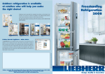
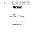
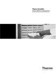
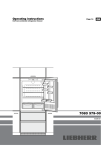
Service Information
After Sales Service International
Service Manual No. 01/2007
LHG/TKD-Ne/11.04.07
Appliance Documentation
ICBN 3056
ICBN 3066
from Index 21
Premium
from Index 20
PremiumPlus
with IceMaker, LED light column,
BioFresh and freezer compartment lighting
Refrigerator for integrated use BioFresh NoFrost
ICBN 3066
ICBN 3056
Page 1/34
01200700SM_gb.doc
Service Manual No. 01/2007
ICBN 3056 from -21 / ICBN 3066 ab -20
Contents
1.0
2.0
3.0
3.1
3.2
4.0
4.1
Operating and control elements ...............................................................................................3
Functions at a glance.................................................................................................................3
Description of the appliance .....................................................................................................4
ICBN 3056: Sensor positions, schematic diagrams ....................................................................5
ICBN 3066: Sensor positions, schematic diagrams ....................................................................6
Main components and their functions......................................................................................7
Electrical components and functions ............................................................................................7
4.1.1 General.................................................................................................................................................. 7
4.1.2 Refrigerator BioFresh compartment...................................................................................................... 8
4.1.3 Freezer compartment.......................................................................................................................... 10
4.2 Refrigeration components and functions ....................................................................................12
4.2.1
4.2.2
4.2.3
4.2.4
General................................................................................................................................................ 12
Refrigerator compartment ................................................................................................................... 12
Freezer compartment.......................................................................................................................... 12
Principle of operation of the refrigerating system ............................................................................... 12
5.0 Assembly instructions / replacement of parts.......................................................................13
5.1 General.......................................................................................................................................13
5.1.1 Electronic control system .................................................................................................................... 13
5.1.2 Soft stop .............................................................................................................................................. 15
5.1.3 Solenoid valve refrigeration circuit ...................................................................................................... 16
5.2 Refrigerator compartment...........................................................................................................17
5.2.1 Disassembling the horizontal separating plate ................................................................................... 17
5.2.2 Disassembling the vertical separating plate, accessing evaporator ................................................... 17
5.2.3 BioFresh air sensor ............................................................................................................................. 18
5.2.4 Refrigerator compartment air sensor .................................................................................................. 18
5.2.5 Evaporator sensor............................................................................................................................... 19
5.2.6 Fan ...................................................................................................................................................... 19
5.2.7 Refrigerator compartment lighting in Premium appliances ................................................................. 20
5.2.8 Refrigerator compartment light column in PremiumPlus-appliances.................................................. 21
5.2.9 BioFresh lighting in PremiumPlus-Geräten......................................................................................... 22
5.2.10 BioFresh pull-out rails ......................................................................................................................... 23
5.2.11 Door magnet........................................................................................................................................ 23
5.2.12 Support rails for sectioned glass shelves ........................................................................................... 24
5.3 Freezer compartment .................................................................................................................25
5.3.1
5.3.2
5.3.3
5.3.4
6.0
6.1
6.2
6.3
7.0
7.1
7.2
7.3
7.4
8.0
8.1
8.2
Air sensor, evaporator module and fan module.................................................................................. 25
Temperature fuse, evaporator sensor and defrost heater .................................................................. 26
Fan and reed PCB .............................................................................................................................. 27
Only ICBN 3066, double solenoid valve IceMaker ............................................................................. 28
Technical data ..........................................................................................................................29
General.......................................................................................................................................29
Refrigerator BioFresh compartment ...........................................................................................29
Freezer compartment .................................................................................................................29
Service menu ............................................................................................................................30
Manual defrosting "H".................................................................................................................30
Demo mode ”d0/d1“..................................................................................................................30
Service mode "L" ........................................................................................................................31
Sensor test (temperature display) and door contact test "E"....................................................32
Error code, troubleshooting ....................................................................................................32
Error code table ..........................................................................................................................32
Troubleshooting VCC compressor / inverter ..............................................................................33
8.2.1 Checking the inverter and the frequency signal.................................................................................. 33
8.2.2 Checking the compressor ................................................................................................................... 34
Page 2/34
Service Manual No. 01/2007
ICBN 3056 from -21 / ICBN 3066 ab -20
1.0 Operating and control elements
1
2
3
4
5
Refrigerator BioFresh compartment
1 : SuperCool function,
button lit = function switched on.
2 : On/Off button
3 : Setting button temperature higher
4 : Setting button temperature lower
6
7
8
9
Freezer compartment
5 : Setting button temperature higher
6 : Setting button temperature lower
7 : On/Off button
8 : SuperFrost function,
button lit = function switched on.
9 : Alarm Off button for audible alarm
2.0 Functions at a glance
Control:
Electronic control system
Temperature display:
Refrigerator compartment:
Freezer compartment:
Actual value
Actual value
Temperature range:
Refrigerator compartment:
Freezer compartment:
+4°C to +9°C
-16°C to -26°C
Temperature alarm:
Refrigerator compartment:
BioFresh compartment:
Freezer compartment:
Not fitted
Not fitted
Visual and audible
Door alarm:
Refrigerator compartment:
Freezer compartment:
Audible
Audible
Fan:
Refrigerator compartment:
Freezer compartment:
Fitted
Fitted
Defrosting:
Refrigerator compartment:
Freezer compartment:
Automatic
Automatic
Interior light:
Refrigerator compartment:
BioFresh compartment:
Freezer compartment:
Fitted
Only ICBN 3066
Only ICBN 3066
Service menu:
Present
Compressor:
VCC
Solenoid valverefrigeration circuit:
Present
Page 3/34
Service Manual No. 01/2007
ICBN 3056 from -21 / ICBN 3066 ab -20
3.0 Description of the appliance
The ICBN is a refrigerator for integrated use with BioFresh and NoFrost freezer compartment.
The appliance has a compressor. The refrigeration control of the refrigerator-BioFresh evaporator and freezer
evaporator is effected via a bi-stable solenoid valve. The two evaporators are connected in series (see
schematic diagram 4.2.4). Therefore the refrigerator compartment can be operated only in conjunction with the
freezer compartment. However, it is possible to operate the freezer compartment on its own.
Refrigerator and BioFresh compartment:
Refrigerator compartment and BioFresh compartment are cooled by way of a common evaporator. The foamedin evaporator is situated behind the rear wall of the liner and is thermally partitioned by an insulated, vertical
separating plate.
A d.c. fan is used for temperature adjustment between refrigerator compartment and BioFresh compartment.
The fan is integrated in the vertical separating plate. If the refrigerator compartment requires refrigeration
(detection by refrigerator compartment air sensor), the fan is switched on. The fan takes in warm air from the
front and blows it past the evaporator in a downward direction. The air that is now cold is conducted past the
BioFresh drawers upwards into the refrigerator compartment.
When it is sufficiently cold in the refrigerator compartment, the fan is switched off. The compressor continues
running and the BioFresh drawers are statically cooled by the falling coldness. The compressor continues to
run/the solenoid valve is at the A setting (cooling + freezing) until such time as the air in the BioFresh
compartment is sufficiently cold (detection by BioFresh air sensor).
Freezer compartment:
The freezer compartment is equipped with a NoFrost rear wall evaporator module, fan module, air sensor and
evaporator sensor. Both sensors can be replaced separately.
The temperature display and the cooling activation/deactivation are effected by the air sensor.
The evaporator sensor serves for the control of the freezer compartment fan and for the defrosting of the
evaporator module.
For defrost water drainage of the refrigerator and freezer compartments, an evaporating tray heated by hot gas is
installed next to the compressor.
Page 4/34
Service Manual No. 01/2007
3.1
ICBN 3056 from -21 / ICBN 3066 ab -20
ICBN 3056: Sensor positions, schematic diagrams
Ambient
temperature sensor
Fan
Rear wall evaporator,
foamed in.
Air sensor
Evaporator sensor
Fan
Lamellar evaporator
Air sensor
Evaporator sensor
Fig. 3.1/ 1: ICBN 3056
Fig. 3.1 / 2: ICBN 3056
Page 5/34
Service Manual No. 01/2007
3.2
ICBN 3056 from -21 / ICBN 3066 ab -20
ICBN 3066: Sensor positions, schematic diagrams
Ambient
temperature sensor
Fan
Rear wall evaporator,
foamed in.
Air sensor
Evaporator sensor
Freezer compartment
lighting
IceMaker
Fan
Lamellar evaporator
Air sensor
Evaporator sensor
Fig. 3.2 / 1: ICBN 3066
Fig. 3.2 / 2: ICBN 3066
Page 6/34
Service Manual No. 01/2007
ICBN 3056 from -21 / ICBN 3066 ab -20
4.0
Main components and their functions
4.1
Electrical components and functions
4.1.1
General
Electronic control system
Type:
Series 6 electronic control system
Components:
Control panel and power PCB
Compressor
Type:
VCC compressor, frequency-controlled.
Function:
On:
Refrigerator compartment evaporator sensor switch-on value
or
freezer compartment air sensor switch-on value
Note: On-delay time (8 mins.) must have elapsed.
Off:
BioFresh air sensor switch-off value
and
freezer compartment air sensor switch-off value
VCC compressor, frequency-controlled.
•
Compressor with 4 different speeds (
1600 / 1900 / 3000 / 3600 rpm).
•
The inverter electronic control is fitted directly on the compressor. The inverter
electronic control controls the compressor with a pulse-width modulated
square-wave voltage.
•
For speed value input, the inverter electronic module receives a square wave
frequency signal from the power PCB.
This frequency signal is output with 56, 71, 87,100 or 117 Hz, depending on
the speed at which the compressor is to run.
Frequency in Hz
56
71
87
100,
0 (signal interruption),
other values than the
defined frequencies
117
Speed in rpm
Compressor On
1600
1900
Operation
Compressor Off
Ideal case
Regular operation
3000
Start-up, signal
interruption, signal fault
3600
SuperFrost
•
Runtime longer than 70 minutes:
Speed increase by one step during compressor operation.
•
Runtime shorter than 50 minutes:
Speed reduction on next start-up.
Troubleshooting see section 8.2 Toubleshooting VCC compressor / inverter
Solenoid valve refrigeration circuit
Type:
Bistable
Function:
Switchover between REFRIGERATOR BIOFRESH COMPARTMENT +
FREEZER COMPARTMENT to only FREEZER COMPARTMENT
Page 7/34
Service Manual No. 01/2007
4.1.2
ICBN 3056 from -21 / ICBN 3066 ab -20
Refrigerator BioFresh compartment
Electronic control system
Setting range:
Display range:
Refrigerator compartment:
+4°C to +9°C
BioFresh compartment:
b1 to b9
(b1: Coldest setting; 0.8K per step)
4°C to 49°C (actual value display)
Temperatures equal to and colder than +4°C are displayed with 4°C.
Functions
SuperCool:
SuperCool On:
Refrigerator compartment sets itself for 6 hours to +4°C. The BioFresh
temperature remains unchanged.
SuperCool Off:
The refrigerator compartment sets itself to the set value.
Defrosting:
- Automatic if solenoid valve in position B (freezer compartment only).
- Automatic during standstill phase of the compressor.
Door alarm:
When:
After the door has been open for 60 seconds.
Audible:
3 beeps.
Refrigerator
compartment air
sensor:
Position:
Behind vertical separating plate.
Function:
- Switches the fan on/off.
- Generates the display value
Evaporator sensor:
Position:
In sensor holder on compartment liner rear wall.
Function:
- Refrigerator compartment evaporator sensor or freezer
compartment air sensor, switches the compressor on.
- The solenoid valve is switched to position A (cooling + freezing).
- Ends defrosting phase.
Position:
Under horizontal separating plate, clipped into vertical separating
plate.
Function:
- BioFresh air sensor and freezer compartment air sensor
switch the compressor off.
- Switches solenoid valve to position B (freezer only).
Position:
On the power PCB.
Function:
Controls the switch-off value of the BioFresh air sensor. That way
temperature fluctuations in the BioFresh compartment are
minimized.
Sensor
BioFresh air sensor:
Ambient air sensor:
An ambient air sensor error is displayed only in the service menu.
In case of fault, the switch-off value of the BioFresh air sensor
is not affected.
Info:
In case of a defect the power PCB has to be replaced.
Page 8/34
Service Manual No. 01/2007
ICBN 3056 from -21 / ICBN 3066 ab -20
Switch
Door switch:
Position:
In front panel.
Type:
Reed PCB
Contact type: Make contact
Function:
Activation via:
magnet on the door, magnet is replaceable.
Switching signal when:
door closed:
fan
interior light
on
off
door open:
fan
interior light
door alarm
off
on
on after 60 sec.
Loads
Fan:
Position:
Function:
Centre of liner ceiling, behind vertical separating plate.
Refrigerator compartment
Compres
Door
Fan
air sensor
s-or
Switch-on value (refrigerator
ON
OFF
CLOSED
compartment warm)
low speed
Switch-on value (refrigerator
ON
ON
CLOSED
compartment warm)
high speed
Switch-on value (refrigerator
ON/OFF
OPEN
OFF
compartment warm)
Switch-off value (refrigerator
CLOSED
ON/OFF
OFF
compartment cold)
/OPEN
e.g. if the refrigerator compartment air sensor is warm, i.e. fan switch-on value is
reached, and the compressor is ON and the door is closed, then the fan is ON high
speed.
Control:
Low speed
High speed
7V/DC
9V/DC
Refrigerator
compartment interior
light
Position:
ICBN 3056:
ICBN 3066:
Inside right.
Inside right and left.
Function:
- Lights up as soon as door is opened.
- Is switched off after door has been open for 15 minutes.
BioFresh compartment
interior light:
(Only ICBN 3066)
Position:
Inside left.
Function:
- Lights up as soon as door is opened.
- Is switched off after door has been open for 15 minutes.
Page 9/34
Service Manual No. 01/2007
4.1.3
ICBN 3056 from -21 / ICBN 3066 ab -20
Freezer compartment
Electronic control system
Setting range:
-16°C to -26°C
Display range:
0°C to -50°C (actual value display)
Values outside the range are indicated by a crossbar.
Functions
Temperature alarm:
Alarm value:
4K warmer than set value.
SuperFrost alarm value: -12°C.
Delay:
20 min.
Visual:
Flashing temperature display.
Audible:
4 beeps.
During start-up:
During start-up the temperature display flashes until
switch-off value has been reached, the audible alarm is
deactivated.
(for example with a set value of -18°C, there must be a temperature of -14°C for at
least 20 mins., then a temperature alarm is issued.)
When the defrosting phase begins, the temperature alarm is suppressed for
1.5 hrs.
Defrosting:
The defrosting phase is started:
- During start-up after 10 hours cumulative compressor running time.
- After a cumulative compressor running time of 10 to 60 hours maximum,
depending on the number/duration of the door openings.
When the defrosting phase begins, the compressor and the fan are switched off
and the defrost heater is switched on.
The defrost heater remains switched on until
- the freezer compartment evaporator sensor has reached +8°C or
- a max. defrosting time of 40 minutes has been reached.
After the end of the heating phase, the compressor is switched on with a 5 minute
delay.
If the SuperFrost function is activated during the defrosting phase, this will not
interrupt defrosting.
Door alarm:
SuperFrost:
When:
After the door has been open for 60 seconds.
Audible:
3 beeps.
SuperFrost On:
Freezer compartment sets itself to -39°C (quantity-controlled, min. 30 hrs., max.
65 hrs.)
The appliance sets itself for at least 30 hours to -39°C. In the following
35 hours, after -39°C has been reached or a total time of 65 hours has elapsed,
SuperFrost ends automatically.
SuperFrost Off:
The freezer compartment sets itself to the set value.
Attention:
If SuperFrost is actuated during a defrosting phase, the SuperFrost function is not
performed before the defrosting phase has run.
Page 10/34
Service Manual No. 01/2007
ICBN 3056 from -21 / ICBN 3066 ab -20
Sensor
Air sensor:
Evaporator sensor:
Position:
Engaged in sensor holder in liner ceiling.
Function:
- Freezer compartment air sensor or refrigerator compartment
evaporator sensor, switches the compressor on.
- BioFresh air sensor and freezer compartment air sensor
switch the compressor off.
- Generates the display value
Position:
Inserted into lamellar evaporator.
Function:
- Freezer compartment evaporator sensor and freezer
compartment air sensor, switch the freezer compartment fan on.
- Ends defrosting phase
Position:
In fan casing.
Type:
Reed PCB
Switch
Door switch:
Contact type: Make contact
Function:
Activation via:
magnet on the inside of the door is replaceable.
Switching signal when:
door closed:
fan
interior light
on
off (ICBN 3066)
door open:
fan
interior light
door alarm
off
on (ICBN 3066)
on after 60 sec.
Loads
Fan:
Position:
At top in middle of freezer compartment.
Function:
On:
- compressor on
and
- freezer compartment door closed
and
- evaporator sensor switch-on value reached.
Switch-on value evaporator sensor:
a) during start-up / after defrosting phase: -25°C.
b) in normal operation 2K colder than freezer compartment
air sensor.
Off:
Defrost heater:
Interior light:
(Only ICBN 3066)
- compressor off
or
- Special case: The refrigerator compartment air sensor is
too warm and the freezer compartment sensor is at least
2K colder than the switch-off value. There is therefore
more power available for the refrigerator
compartment!
Position:
Clipped into lamellar evaporator.
Function:
Keeps the lamellar evaporator free of ice.
Control, see: Functions Defrosting
Position:
On crosspiece.
Function:
- Lights up as soon as door is opened.
- Is switched off after door has been open for 15 minutes.
Page 11/34
Service Manual No. 01/2007
4.2
4.2.1
ICBN 3056 from -21 / ICBN 3066 ab -20
Refrigeration components and functions
General
Compressor
Compressor:
VCC compressor, frequency-controlled.
Solenoid valve
Solenoid valve:
4.2.2
Bistable
Refrigerator compartment
Evaporator
Design:
Rear wall evaporator
Type of installation:
Foamed-in
Injection point:
Top centre
Flow sequence:
See 4.2.4 Operating principle of refrigerating system
4.2.3
Freezer compartment
Evaporator
Design:
Lamellar evaporator
Type of installation:
Free-standing between air duct cover and compartment liner.
Injection point:
Top right on lamellar evaporator.
Flow sequence:
See 4.2.4 Principle of operation of the refrigerating system
4.2.4
Principle of operation of the refrigerating system
Refrigerator BioFresh
compartment evaporator
Condenser
Freezer compartment
evaporator
Solenoid valve
Compressor
Fig. 4.2.4
Page 12/34
Service Manual No. 01/2007
ICBN 3056 from -21 / ICBN 3066 ab -20
5.0 Assembly instructions / replacement of parts
5.1
General
5.1.1
Electronic control system
Covers:
Disengage covers at the marked points.
Fig. 5.1.1 / 1
PCB carrier:
Draw out front casing in a forward direction and uncover the cables.
Fig. 5.1.1 / 2
Page 13/34
Service Manual No. 01/2007
ICBN 3056 from -21 / ICBN 3066 ab -20
Front panel:
Release marked locks and remove front panel.
PCB mount:
Release marked locks and remove PCB mount.
Fig. 5.1.1 / 3
PCB:
Release marked locks with screwdriver and draw PCB out of the PCB carrier.
Fig. 5.1.1 / 4
Disengage the other PCBs and remove them from the PCB mounts.
Fig. 5.1.1 / 5
Page 14/34
Service Manual No. 01/2007
5.1.2
ICBN 3056 from -21 / ICBN 3066 ab -20
Soft stop
Integrated on the doors, the SoftSystem cushions movement when the doors are closed. The door is closed
automatically from an opening angle of approx. 30°.
Soft stop mechanism:
- Undo marked screw on hinge side and detach holder for soft stop mechanism.
- Lever off retaining clip with screwdriver and detach soft stop mechanism from
spherical head.
Fig. 5.1.2/ 1 Soft stop mechanism
Fig. 5.1.2/ 2 Screw hinge side
Fig. 5.1.2/ 3 Holder for soft stop mechanism
Fig. 5.1.2/ 4 Detaching soft stop mechanism from
spherical head
Fig. 5.1.2/ 5 Soft stop mechanism
detached
Page 15/34
Service Manual No. 01/2007
5.1.3
ICBN 3056 from -21 / ICBN 3066 ab -20
Solenoid valve refrigeration circuit
Solenoid valve
When detaching the capillaries, pay attention that they are properly re-connected.
Marking on solenoid valve cover:
KS
GS
Capillary
refrigerator
: Capillary refrigerator compartment
: Freezer compartment capillary
Freezer
compartment
capillary
Fig. 5.1.3
Page 16/34
Service Manual No. 01/2007
ICBN 3056 from -21 / ICBN 3066 ab -20
5.2
Refrigerator compartment
5.2.1
Disassembling the horizontal separating plate
•
•
Remove upper BioFresh drawer.
Draw out separating plate in marked direction (no lock).
Horizontal separating
plate
Fig. 5.2.1 / 1
5.2.2
•
•
•
•
•
Disassembling the vertical separating plate, accessing evaporator
Disassemble the horizontal separating plate.
Remove glass shelves.
Disengage BioFresh air sensor.
Release fastening screws (see Fig. 5.2.2/ 1) of the separating plate.
Pull out refrigerator compartment air sensor and disconnect fan cable (see Fig. 5.2.2/ 2).
Fastening screws
Fan connector
Refrigerator
BioFresh air sensor
Fig. 5.2.2 / 2
Fig. 5.2.2 / 1
Page 17/34
Service Manual No. 01/2007
ICBN 3056 from -21 / ICBN 3066 ab -20
During assembly pay attention that the retaining lugs of the vertical separating plate are slipped into the
grooves of the compartment liner for fixing the separating plate at the top.
Retaining
Grooves in the
compartment liner
Fig. 5.2.2 / 3
5.2.3
Fig. 5.2.2 / 4
BioFresh air sensor
BioFresh air sensor: Proceed as described under 5.2.1 Disassembling the horizontal separating plate and
5.2.2 Disassembling the vertical separating plate, accessing evaporator.
BioFresh air sensor
Fig. 5.2.3
5.2.4
Refrigerator compartment air sensor
Refrigerator compartment air sensor:
horizontal
- Proceed as described under 5.2.1 Disassembling the
separating plate and 5.2.2 Disassembling the vertical separating
plate, accessing evaporator.
- Draw refrigerator compartment air sensor (Fig. 5.2.4/ 2) from separating
plate.
Refrigerator
compartment air
sensor
Fig. 5.2.4 / 1
Fig. 5.2.4 / 2
Page 18/34
Service Manual No. 01/2007
5.2.5
ICBN 3056 from -21 / ICBN 3066 ab -20
Evaporator sensor
Evaporator sensor:
- Proceed as described under 5.2.1 Disassembling the horizontal separating plate and
5.2.2 Disassembling the vertical separating plate, accessing evaporator.
- Unscrew sensor holder (Fig. 5.2.5 ) and unclip evaporator sensor.
Fig. 5.2.5 Evaporator sensor
5.2.6
Fan
Fan:
- Proceed as described under 5.2.1 Disassembling the horizontal separating plate and
5.2.2 Disassembling the vertical separating plate, accessing evaporator.
- Disconnect fan, release retaining clamps (Fig. 5.2.6/ 1) and use a screwdriver to press
the
fan from the rubber support at the marked locations (Fig. 5.2.6/ 2).
Note:
The direction of installation (direction of air current) is indicated by an arrow.
The arrow (see Fig. 5.2.6/ 2) has to point in the direction of the compartment liner (rear
wall of appliance).
Fig. 5.2.6 / 2
Fig. 5.2.6 / 1
Page 19/34
Service Manual No. 01/2007
5.2.7
ICBN 3056 from -21 / ICBN 3066 ab -20
Refrigerator compartment lighting in Premium appliances
Refrigerator compartment LED lighting:
- Unlock light cover using short screwdriver (Fig. 5.2.7/ 1).
- Undo fastening screws of light housing (Fig. 5.2.7/ 2).
- Unlock and remove connector (Fig. 5.2.7/ 3).
- Unlock LED lighting unit at the connector and cooling plate
(Fig. 5.2.7/ 4).
Fig. 5.2.7 / 1
Fig. 5.2.7 / 2
Fig. 5.2.7 / 3
Fig. 5.2.7 / 4
Page 20/34
Service Manual No. 01/2007
5.2.8
ICBN 3056 from -21 / ICBN 3066 ab -20
Refrigerator compartment light column in PremiumPlus-appliances
LED light column:
- Using small screwdriver, turn cover cap with slot downwards.
- Insert screwdriver in slot and remove cover cap.
- Undo screws of light column.
Cover cap
Fig. 5.2.8 / 2
Fig. 5.2.8 / 1
LED PCB:
- Unlock and pull off connector (Fig. 5.2.8/ 3).
- Unlock PCB and connector socket at the marked locations (Fig. 5.2.8/ 4).
- Lift PCB at an angle from the light cover.
Connector
Fig. 5.2.8 / 3
INFO
Fig. 5.2.8 / 4
One LED group comprising 3 LEDs is used for each illuminated support rib.
If a single LED of an LED group is defective, the entire LED group is inoperative.
All the other LEDs continue to shine.
LED groups per support rib
Fig. 5.2.8 / 5
Page 21/34
Service Manual No. 01/2007
5.2.9
ICBN 3056 from -21 / ICBN 3066 ab -20
BioFresh lighting in PremiumPlus-Geräten
BioFresh LED lighting:
- Unlock lighting unit (Fig. 5.2.9/ 2).
- Unlock and pull off connector (Fig. 5.2.9/ 3).
- Unlock LED PCB and remove PCB (Fig. 5.2.9/ 4).
Fig. 5.2.9 / 2
Fig. 5.2.9 / 1
Unlocking PCB
Unlocking
connector
Fig. 5.2.9 / 3
Fig. 5.2.9 / 4
Page 22/34
Service Manual No. 01/2007
ICBN 3056 from -21 / ICBN 3066 ab -20
5.2.10 BioFresh pull-out rails
Pull-out rail:
- Press in lock and press rail to the rear (Fig. 5.2.10 / 1).
- Support is replaceable (Fig. 5.2.10/ 3).
Fig. 5.2.10 / 2
Fig. 5.2.10 / 1
Fig. 5.2.10 / 3
5.2.11 Door magnet
Magnet holder:
Press marked locating lugs together and detach magnet holder upwardly.
Magnet
holder
Fig. 5.2.11 / 2
Fig. 5.2.11 / 1
Page 23/34
Service Manual No. 01/2007
ICBN 3056 from -21 / ICBN 3066 ab -20
5.2.12 Support rails for sectioned glass shelves
Rails:
These plastic rails support the sectioned glass shelves. The marking R for right and
L for left is impressed inside. The toothed profile has to rest against the underside of the
supporting ribs of the compartment liner.
Support rail
Toothed profile for
better fixation
Fig. 5.2.12 / 1
Fig. 5.2.12 / 2
Page 24/34
Service Manual No. 01/2007
5.3
5.3.1
ICBN 3056 from -21 / ICBN 3066 ab -20
Freezer compartment
Air sensor, evaporator module and fan module
Air sensor:
Engaged in sensor holder on air duct cover.
Evaporator module:
- Remove drawers and glass shelves in freezer compartment.
- Disengage air sensor.
- Undo the screws marked in Fig. 5.3.1/ 1and remove the rear wall.
- Lift the evaporator module to swing it out in a forward direction.
Fan module:
Unscrew the marked screws and uncover cable (Fig. 5.3.1/ 3).
Air sensor
Fig. 5.3.1/ 2 Unlocking IceMaker (only ICN 3066)
Fig. 5.3.1/ 1 Freezer compartment with air duct
Fig. 5.3.1 / 3 Fan module
Page 25/34
Service Manual No. 01/2007
5.3.2
ICBN 3056 from -21 / ICBN 3066 ab -20
Temperature fuse, evaporator sensor and defrost heater
Temperature fuse:
The temperature fuse can be replaced separately with a conversion kit.
The conversion kit comprises: - 1 temperature fuse
- 2 compression connectors
- 2 shrinkdown tubings
Please note:
Always attach the compression connector to the red and blue lines of the temperature
fuse. As soon as the white line of the defrost heater is cut, the defrost heater is
destroyed.
Evaporator sensor:
- Remove cover plate by cutting the adhesive tapes at the right and left.
- Draw the evaporator sensor to the right, out of the lamellar evaporator.
Defrost heater:
Is clipped into the evaporator fins. Can be replaced if defective.
Temperature fuse
Fig. 5.3.2/ 1 Evaporator module
Fig. 5.3.2/ 2 Cutting adhesive tape
Defrost heater
Evaporator sensor
Fig.. 5.3.2/ 3 Evaporator sensor, defrost heater
Page 26/34
Service Manual No. 01/2007
5.3.3
ICBN 3056 from -21 / ICBN 3066 ab -20
Fan and reed PCB
Reed PCB:
- Disengage cover of reed PCB (see Fig. 5.3.3/ 2).
- Disconnect Reed PCB.
Æ Note mounting direction of reed PCB. Reed relay points forwards.
Fan:
- Disconnect Reed PCB.
- Extricate cable from fan module.
- Open retaining clip for cable.
- Disconnect fan cable.
- Remove fan module
- Remove fan vanes.
- Remove fan from holder.
Fan module
Reed PCB
Fig. 5.3.3/ 1 Fan module with reed PCB
Fig. 5.3.3/ 2 Reed PCB
Holding clip
Fig. 5.3.3 / 3
Fig. 5.3.3 / 4 Fan
Page 27/34
Service Manual No. 01/2007
5.3.4
ICBN 3056 from -21 / ICBN 3066 ab -20
Only ICBN 3066, double solenoid valve IceMaker
Solenoid valve
- Undo marked screw (see Fig. 5.3.4/ 1).
- Remove cover.
Double solenoid valve
Fig. 5.3.4 / 1
Fig. 5.3.4 / 2
Page 28/34
Service Manual No. 01/2007
ICBN 3056 from -21 / ICBN 3066 ab -20
6.0 Technical data
6.1
General
Sensor values:
6.2
Refrigerator compartment:
Freezer compartment:
Air and evaporator sensor
Air sensor and evaporator sensor
Temperature °C
Resistance value kOhm
+35
+30
+25
+20
+15
+10
+5
0
-5
-10
-15
-20
-25
-30
-35
3.1
3.8
4.7
5.9
7.3
9.3
11.9
15.3
19.8
25.9
34.1
45.3
60.8
82.3
112.8
Refrigerator BioFresh compartment
Interior light
PremiumPlus:
Refrigerator compartment:
Wattage:
approx. 3 watts
Voltage:
approx. 13 volts/DC, with LED lighting connected.
approx. 13 volts/DC, with LED lighting disconnected.
BioFresh compartment:
Wattage:
approx. 1 watt
Voltage:
approx. 13 volts/DC, with LED lighting connected.
approx. 13 volts/DC, with LED lighting disconnected.
Interior light
Premium:
Wattage:
Voltage:
3 watts
approx. 10 volts/DC, with LED lighting connected.
approx. 16 volts/DC, with LED lighting disconnected.
Fan:
Wattage:
Voltage:
1.6 watts
12 volts/DC (6V to 15V)
6.3
Freezer compartment
Interior light
PremiumPlus:
Wattage:
Voltage:
approx. 4 watts
approx. 6.5 volts/DC, with LED lighting connected.
approx. 13 volts/DC, with LED lighting disconnected.
Fan:
Wattage:
Voltage:
1.9 watts
230 volts/AC
Defrost heater:
Wattage:
Voltage:
136 watts
230 volts/AC
Temperature fuse:
Trip temperature: +93°C (Is faulty after tripping and has to be replaced)
Page 29/34
Service Manual No. 01/2007
7.0
ICBN 3056 from -21 / ICBN 3066 ab -20
Service menu
The service menu may be used only by customer service technicians.
7.1
Manual defrosting "H"
Step
Display
Operation
Display following
operation
Testing option /
Info
„H“ flashes at the same
time as the SuperFrost
and SuperCool LED
Service menu
active.
Service menu start
Press “On/Off” and
"SuperFrost"
simultaneously for 3
seconds.
1
Actual value
2
"H" flashes at the same time
as the SuperFrost and
Press "SuperFrost"
SuperCool LED
Refrigerator compartment:
+5°C
Manual defrost
Freezer compartment:
activated
"A" flashes
Manual defrost automatically stopped.
Manual defrost can be ended prematurely by switching the freezer compartment off and back on again.
7.2
Demo mode ”d0/d1“
Step
Display
Operation
Display following
operation
Testing option / Info
Service menu start
Press “On/Off” and
"SuperFrost"
simultaneously for 3
seconds.
„H“ flashs at the same
time as the SuperFrost Service menu active.
and SuperCool LED
1
Actual value
2
"H" flashs at the same time
as the SuperFrost and
SuperCool LED
Press "Up" once
"d1" or "d0" flash at the
same time as
Service menu active.
SuperFrost and
Stepwise demo mode
SuperCool LED
2a
d1
Press "SuperFrost"
Set value
Demo mode On
2b
d0
Press "SuperFrost"
Set value
Demo mode Off
Demo mode (Demo mode can be deactivated only via service menu, not by “Off/On”.)
Operation switches to the mode wanted, demo mode or normal mode, as soon as "SuperFrost" has been
actuated.
Page 30/34
Service Manual No. 01/2007
7.3
ICBN 3056 from -21 / ICBN 3066 ab -20
Service mode "L"
Step
Display
Operation
Display following
operation
Testing option / Info
Service menu start
1
Actual value
Press “On/Off” and
"SuperFrost"
simultaneously for 3
seconds.
"H" flashes at the same
time as the SuperFrost
and SuperCool LED
Service menu active.
Service mode
-- test display LED, door contact, potentiometer -1
"H" flashes at the same
time as the SuperFrost
and SuperCool LED
Press "Up" twice
„L“ flashes at the same
time as SuperFrost and
SuperCool LED
Service mode selected
2
„L“ flashes at the same
time as SuperFrost and
SuperCool LED
Press "SuperFrost"
"rd" flashes
Service mode activated
3
"rd" flashes
Doors closed and open
All button LEDs and
display segments shine
Door contact, LEDs,
display
4
All button LEDs and
display segments shine
Press all the buttons one
after the other.
"L0" shines
Button actuation is
confirmed by beep
"L0" shines
All OFF
"L1" shines
- Compressor low
speed
- solenoid valve at
setting B
After step 4, actuation of the last button, a beep sounds.
Service mode
-- testing electric loads-5
6
End
"L0" shines
"L0" shines
No operation
Press "Up"
7
"L1" shines
Press "Up"
"L2" shines
- Compressor high
speed
- solenoid valve at
setting A
8
"L2" shines
Press "Up"
„L3“ shines
Freezer compartment
fan On
9
"L3" shines
Press "Up"
"L4" shines
Freezer compartment
defrost heater On
10
"L4" shines
Press "Up"
"L5" shines
Light On
11
"L5" shines
Press "Up"
"L7" shines
Refrigerator BioFresh
compartment fan, low
speed
12
"L7" shines
Press "Up"
"L8" shines
Refrigerator BioFresh
compartment fan,
high speed
Press "On/Off"
Page 31/34
Service Manual No. 01/2007
7.4
ICBN 3056 from -21 / ICBN 3066 ab -20
Sensor test (temperature display) and door contact test "E"
Step
Display
Operation
Display following
operation
Testing option / Info
Service menu start
1
Actual value
Press “On/Off” and
"SuperFrost"
simultaneously for 3
seconds.
"H" flashes at the same
time as the SuperFrost
and SuperCool LED
Service menu active.
Sensor test and door contact test (sensor values without offset, appliance in service mode)
1
"H" flashes at the same
time as the SuperFrost
and SuperCool LED
Press "Up" three times
„E“ flashes at the same
Sensor test mode
time as SuperFrost and
selected
SuperCool LED
2
„E“ flashes at the same
time as SuperFrost and
SuperCool LED
Press "SuperFrost"
"E0" flashes alternately
BioFresh air sensor
with sensor temperature
3
"E0" flashes alternately
with sensor temperature
Press "Up"
Refrigerator
"E1" flashes alternately
compartment air
with sensor temperature
sensor
4
"E1" flashes alternately
with sensor temperature
Press "Up"
Evaporator sensor for
"E2" flashes alternately
refrigerator
with sensor temperature
compartment
5
"E2" flashes alternately
with sensor temperature
Press "Up"
"E3" flashes alternately Freezer compartment
with sensor temperature air sensor
6
"E3" flashes alternately
with sensor temperature
Press "Up"
„E4“ flashes alternately Freezer compartment
with sensor temperature evaporator sensor
7
"E4" flashes alternately
with sensor temperature
Press "Up"
"E7" flashes alternately
Ambient air sensor:
with sensor temperature
8
"E7" flashes alternately
with sensor temperature
Press "Up"
Door contact freezer
„E8“ flashes alternately compartment
with "0" or "1"
(0 = door closed,
1 = door open)
Press "Up"
Door contact
refrigerator BioFresh
compartment
(0 = door closed,
1 = door open).
„E8“ flashes alternately
with "0" or "1"
9
End
"E9" flashes alternately
with "0" or "1"
Press On/Off twice
8.0 Error code, troubleshooting
8.1
Error code table
Error code
Defective component
Emergency operation
F0
BioFresh air sensor
Compressor 10 minutes ON and 40 minutes OFF.
F1
Refrigerator compartment air sensor
Compressor 10 minutes ON and 40 minutes OFF
F2
Refrigerator compartment evaporator sensor Compressor 10 minutes ON and 40 minutes OFF.
F3
Freezer compartment air sensor
Compressor endurance run
F4
Evaporator sensor, freezer compartment
Compressor endurance run
FU *
Ambient air sensor:
Ambient temperature of +25°C is predetermined
* Error of ambient temperature sensor is checked and displayed only in the control panel test of the service mode.
Page 32/34
Service Manual No. 01/2007
ICBN 3056 from -21 / ICBN 3066 ab -20
8.2
Troubleshooting VCC compressor / inverter
8.2.1
Checking the inverter and the frequency signal
Connect appliance to a power meter.
Switch on appliance.
no
Is the
compressor
running?
Is the compressor
running after 90
seconds?
no
see 8.2.2
yes
yes
Frequency signal faulty / not
connected or power PCB faulty.
Press SF
Does the speed
increase, higher
power input?
yes
Inverter; power PCB and
frequency cable are in order.
no
Switch appliance off
no
Does the
compressor
stay at a
standstill?
Frequency signal faulty / not
connected or power PCB faulty.
yes
Inverter faulty
Attention: In case of interruption of the frequency signal, the compressor starts
only after 90 seconds!!
Page 33/34
Service Manual No. 01/2007
8.2.2
ICBN 3056 from -21 / ICBN 3066 ab -20
Checking the compressor
Fault profile: Compressor does not run (not even after a waiting time of 90 secs)
In the service menu select service mode L1 (low speed) or L2 (high speed). If the compressor now
starts there was probably an operator error. Otherwise proceed as described below.
At the inverter, line voltage (230V) must be applied between N and 1/C.
Is voltage
applied to the
inverter?
no
Fault at cable connection /
connector or power PCB.
yes
Is the
compressor
running?
yes
Presumably operator error.
Check speed increase!
no
Pull off frequency signal connector (lilac)
from the inverter,
wait 90 secs
Is the
compressor
running?
yes
no
Replace inverter electronic module.
If the compressor still does not run,
replace the compressor.
Then replace the inverter again.
Page 34/34
Power PCB or inverter fault.