1
OPERATING MANUAL Version 01/11 PRO-BOT 128 Item no. 19 19 19 (Kit) Item no. 19 20 20 (ready-to-use device) Table of Contents Page 1. 2. 3. 4. 5. 6. Introduction .............................................................................................................................................................................................. 4 Intended use ............................................................................................................................................................................................. 5 Symbol explanation ................................................................................................................................................................................. 5 Safety instructions ................................................................................................................................................................................... 6 General battery and rechargeable battery notes .................................................................................................................................. 7 System description .................................................................................................................................................................................. 8 a) Performance specifications ................................................................................................................................................................... 8 b) Chassis and drive .................................................................................................................................................................................. 8 c) Sensors, actors and extensions ............................................................................................................................................................ 8 d) Control computer C-Control PRO 128................................................................................................................................................... 9 7. General information ............................................................................................................................................................................... 10 a) Electrostatic discharges ...................................................................................................................................................................... 10 b) Supply voltage ..................................................................................................................................................................................... 10 c) Replica ................................................................................................................................................................................................ 10 d) General information about the design of a circuit ................................................................................................................................ 10 e) Required Tools .................................................................................................................................................................................... 12 8. Preliminary mechanical work ................................................................................................................................................................ 13 a) Engine pinion ...................................................................................................................................................................................... 13 b) Ping pong ball ..................................................................................................................................................................................... 13 c) Photo transistors and IR diodes .......................................................................................................................................................... 14 d) Wheel sensors .................................................................................................................................................................................... 14 9. Soldering instructions ........................................................................................................................................................................... 15 a) General information ............................................................................................................................................................................. 15 b) Producing a clean welding spot ........................................................................................................................................................... 16 c) Removing wrongly installed parts by means of soldering .................................................................................................................... 16 10. Assembly stage I: Installing the assembly elements on the circuit board ....................................................................................... 17 a) Soldering on the brass shafts .............................................................................................................................................................. 17 b) Resistors ............................................................................................................................................................................................. 18 c) Light-dependent resistors (LDR) ......................................................................................................................................................... 19 d) Capacitor ............................................................................................................................................................................................. 19 e) Diode ................................................................................................................................................................................................... 20 f) LEDs and IR LEDs .............................................................................................................................................................................. 20 g) Photo transistors ................................................................................................................................................................................. 21 h) Choke .................................................................................................................................................................................................. 21 i) Infrared receiver .................................................................................................................................................................................. 22 j) IC mounts ............................................................................................................................................................................................ 22 k) Integrated circuits ................................................................................................................................................................................ 22 l) Sound transducer ................................................................................................................................................................................ 23 m) Microphone capsule ............................................................................................................................................................................ 23 n) Buttons ................................................................................................................................................................................................ 23 o) Switch ................................................................................................................................................................................................. 23 p) Jumpers: ............................................................................................................................................................................................. 24 q) Socket board for C control PRO .......................................................................................................................................................... 24 r) Ribbon cables, pin plugs and pin header ............................................................................................................................................ 24 s) Assembly of the motors and the transmission ..................................................................................................................................... 26 t) Circuit board spacer and battery support ............................................................................................................................................ 27 2 Page 11. Assembly stage II: Sight inspection of the circuit board ................................................................................................................... 28 a) Assembly plan (drive unit) ................................................................................................................................................................... 28 b) Assembly plan (main unit) ................................................................................................................................................................... 30 c) Assembly plan (bread board) .............................................................................................................................................................. 32 12. Circuit diagrams ..................................................................................................................................................................................... 34 13. Software installation .............................................................................................................................................................................. 40 a) CD content .......................................................................................................................................................................................... 40 b) Installation of the programming interface "IDE" ................................................................................................................................... 40 c) Programming cable (Voltcraft USB programmer) ................................................................................................................................ 41 d) Commissioning and testing ................................................................................................................................................................. 41 e) The PRO-BOT128 library .................................................................................................................................................................... 43 14. Troubleshooting ..................................................................................................................................................................................... 47 15. Final adjustment work ........................................................................................................................................................................... 50 16. Parts lists ................................................................................................................................................................................................ 51 17. Block diagram PRO-BOT128 ................................................................................................................................................................. 53 18. Expansion ideas ..................................................................................................................................................................................... 54 19. Cleaning .................................................................................................................................................................................................. 55 20. Disposal .................................................................................................................................................................................................. 55 a) General information ............................................................................................................................................................................. 55 b) Batteries and rechargeable batteries .................................................................................................................................................. 55 3 1. Introduction Dear Customer, Thank you for purchasing the PRO-BOT 128. This mobile robot is equipped with a programmable microcomputer, which allows you to define the behaviour and the basic reactions of the robot to external stimulations. We developed the PRO-BOT128 with the aim to meet the high expectations of our customers regarding quality and function. If you purchased the assembly kit, the concept of the PRO-BOT128 was designed in such a way that experienced electronic technicians as well as beginners can assemble and commission it in just a few hours. Apart form the circuit board, the robot only contains standard parts that can be processed with normal fine motor skills and easy to obtain components. The PRO-BOT128 is therefore perfectly suited for hobby constructors who want to become involved in process-controlled circuits, for pupil and student projects, advanced education or adult education centers. Besides its C-Control PRO 128 RISC processor, the Pro-Bot 128 has two motors, which can be controlled independently of each other, an optical line tracing unit, an optical collision detector, two rotary speed sensors for the wheels, four visual display LEDs, a 64k EEProm, an acoustic sensor, two light sensors, and the possibility to measure and control its own operating voltage as a special feature. This product meets the requirements of current statutory, European and national guidelines. The CE requirements must be observed when using this product. This user manual is part of this product. It contains important details concerning operation and handling. Bear this in mind when you pass on this product to others. Therefore, keep this user manual for future reference. Prior to commissioning the PRO-BOT128 or connected devices, please read this entire instruction manual carefully! It explains the correct use and points out possible risks. Any company or product names are trademarks of their respective owners. All rights reserved. In case of any technical inquiries, contact or consult: Tel. no.: +49 9604 / 40 88 80 Fax. no.: +49 9604 / 40 88 48 E-mail: [email protected] Mon. to Thur. 8.00am to 4.30pm, Fri. 8.00am to 2.00pm 4 2. Intended use This mobile robot is equipped with a programmable microcomputer, which allows you to determine basic behaviour patterns and reactions of the robot to external influences yourself. The robot PRO-BOT128 was developed as an experimental platform for all electronic technicians interested in robotics. In practical tests, it visualises the influence and effects of software parameters as well as physical parameters via the corresponding sensor technology. Any use other than that described above is not permitted. The product is not a toy and should be kept out of reach of children under 14 years of age! It may only be used in closed, dry indoor rooms. The product must not get damp or wet. Use other than that described above can lead to damage to the product and may involve additional risks such as short circuits, fire, electrical shocks etc. The product is not a toy and should be kept out of reach of children under 14 years of age! Observe all safety notices in these operating instructions! They contain important information regarding the handling of the product. You should also heed the additional safety instructions in each chapter of these instructions. 3. Symbol explanation This symbol is used when your health is at risk, e.g. through an electric shock. The symbol with the exclamation mark points out particular dangers associated with handling, function or operation. The "hand" symbol indicates special tips and operating information. 5 4. Safety instructions The guarantee/warranty will be void if damage is incurred resulting from non-compliance with the operating instructions. Liability for any and all consequential damage is excluded! We do not assume any liability for damage to property or personal injury caused by improper use or the failure to observe the safety instructions! In such cases the guarantee is voided. General information • Due to the open type of construction, the PRO-BOT128 has sharp edges and corners. Danger of injury when touched! Do not reach into the drive! • The product is not a toy and should be kept out of reach of children under 14 years of age! Keep the product out of the range of children. They may reach into the drive. Risk of injury! • Depending on programming, you may experience sudden drive and steering motions and the motors may start up unexpectedly! • Do not operate the robot near pets that roam freely. • The robot does not have a casing and contains uncovered components and strip conductors. Do not cause any short circuits due to accidentally placed metal parts or tools. • Prior to commissioning the robot, you have to remove all containers with liquid from its range, e.g. coffee pots, bottles or vases. • Only use the robot in clean, domestic surroundings. Dirt, dust, foreign objects and dampness destroy the mechanics and the electronics. • The admissible ambient temperature may not fall short of or exceed 0°C to 40°C during operation. • Do not operate the robot near flammable or explosive liquids, gases, or dusts. • Do not operate the robot on table tops or areas where it might fall off. Also keep in mind the climbing abilities of the robot. • For safety seasons, you should not operate the robot unsupervised. • Only use the robot in moderate climate regions and not in a tropical climate. • Do not leave packing material unattended. This may become dangerous playing material for children. • On industrial sites the accident prevention regulations of the association of the industrial workers' society for electrical equipment and utilities must be followed. • If the product is used at schools, training facilities, do-it-yourself and hobby workshops, it should not be handled unless supervised by trained, responsible personnel. • The robot is not designed for commercial use! • Should any questions arise that are not answered in this operating manual, contact our Technical Advisory Service or another expert. Notices on limited warranty and liability The core of the robot is the "C-Control PRO128" control computer. The boot loader in the microprocessor and the corresponding programming software are enclosed. Conrad Electronic SE will not assume any warranty that the performance features meet individual demands or that the software in the microprocessor and the PC software work interruption and error-free at all times. The user bears the entire risk regarding quality and performance of the device including all software. Conrad Electronic SE guarantees the function of the provided application examples when observing the conditions specified in the technical data. Should the robot or the PC software turn out to be inadequate or faulty, the customer assumes all arising costs for service, repair or corrections. The warranty of Conrad Electronics SE is limited exclusively to the exchange of devices within the warranty period in case of apparent hardware defects like mechanical damage, missing or wrong equipment of electronic parts with the exception of integrated circuits with sockets and jumpers. We will not assume any liability for damage arising directly through application of the robot or as a consequence of this. Claims based on mandatory statutory regulations on product liability remain exempt from this. 6 Each robot kit leaves our company in an impeccable and function-tested state! Conrad Electronic SE offers a warranty of 24 months for the PRO-BOT128. Within this time, we will remedy possible transport damage upon delivery, production defects or breakdowns of the device free of charge. If the performance features of the robot do not meet your individual requirements, please use our 14-day money-back guarantee. In this period, return the device to us without visible signs of use in its original packaging to receive a refund or offset the amount. All periods are valid as of the date of the invoice respectively sales slip. Conrad Electronic SE will not assume any liability for consequential damages to assets or persons caused by the application and operation of the robot! Service Conrad Electronic SE provides a competent service team to assist you. Each inquiry will be processed as fast as possible. Special inquiries will be passed on to the development engineers at CTC. To avoid unnecessary delays, we kindly ask you to read this instruction manual, the online help of the programming software, the text and example files and, if possible, the information pages in the Internet prior to posting your request. In many cases, this leads to the solution of a problem! 5. General instructions relevant to batteries and rechargeable batteries • Batteries must be kept out of the reach of children. • Do not let batteries/rechargeable batteries lie around openly. There is a risk of batteries being swallowed by children or pets. In such a case, seek instant medical attention! • Batteries/rechargeable batteries must never be short-circuited, taken apart or thrown into fire. There is a risk of explosion! • Leaking or damaged batteries/rechargeable batteries may cause acid burns when coming into contact with skin, therefore use suitable protective gloves. • Do not recharge normal batteries. There is a risk of fire and explosion! Only charge rechargeable batteries which are intended for this purpose; use suitable rechargeable battery chargers. • Please observe correct polarity (plus/+ and minus/-) when inserting the batteries/rechargeable batteries. Danger of fire and explosion! • If the device is not used for a longer period of time (e.g. storage), take out the inserted batteries (or rechargeable batteries) to avoid damage from leaking batteries/rechargeable batteries. Recharge the rechargeable battery about every 3 months, because otherwise there may a so called deep discharge because of the self-discharge, which makes the rechargeable batteries useless. • Always exchange the entire set of batteries or rechargeable batteries. Do not mix full batteries/rechargeable batteries with half-full ones Always use batteries or rechargeable batteries of the same type and manufacturer. • Never mix batteries and rechargeable batteries! Use either batteries or rechargeable batteries. 7 6. System description a) Performance features The PRO-BOT128 is a programmable microcomputer equipped with numerous sensors and mounted on a chassis with differential drive. With proper programming, the PRO-BOT128 is a fully functional small robot able to recognize external influences and react to them. At the same time, the PRO-BOT128 offers an ideal basis for own expansions with respect to sensors and actors, e.g. for competitions. The power is supplied by 4 NiCd/ NiMH rechargeable batteries (or temporarily and with restrictions, 4 high-quality alkali-manganese batteries) b) Chassis and drive The robot PRO-BOT128 runs on a differentially driven chassis which allows it to turn in place and drive into the desired direction. The advantage of this type of drive is that rotations and steering motions do not require more space than the robot's own diameter. Its round design in connection with the differential drive also prevents it from getting stuck in corners. The drive motors consist of high-quality industrial motors with a long service life and a very good degree of effectiveness. This results in long operating times with one battery charge. The transmissions consist of one pinion each with 10 teeth on the motor shaft and two step wheels with 10/50 and 12/50. Two reflex light barriers per drive wheel allow path measuring or speed control in connection with an encoder disk (affixed on the center gear wheel). c) Sensors, actors and extensions The following sensors and actors allow the programmer to develop very complex interactions with ambient stimulations and manifold reactions. Sensors • 2 light sensors • 2 odometers • 1 line sensors • 1 touchless IR anti-collision sensor (ACS) • 1 sound sensor • 1 sensor for the operating voltage Actors • 2 DC electronic drives with continuous speed adjustment forward/backward • 1 beep for emitting sound signals • 4 status LEDs • 1 line LED for the line sensor Expansions • 64K I²C EEProm • Experimental circuit board 8 d) Control computer C-Control PRO 128 (Conrad item no: 198219) The control computer of the PRO-BOT128 is a computer of the C-Control PRO series. This is a compact module for universal application in measuring, control and regulation tasks and also able to perform serial data transmission and data storage processes. The control computer contains an advanced microprocessor, which allows the programming of the module in the popular and easy to learn programming languages BASIC and C. With just a few lines of BASIC or C source text, the control computer turns into an intelligent alarm system, a complex data recording system, a control unit for a heating system or – as in this case – the "brain" of a small robot model. Technical data of the C-Control PRO 128: • • • • • • • • • • • • • • • • • • • • • • 110kB available flash memory 4kB SRAM 4kB EEPROM 3kB variable memory 2 x UART SPI I²C bus 10-bit ADC with 8 channels Analog comparator 5 PWM-DAC 53 digital I/Os 8 external interrupts 2 x 8-bit timer 2 x 16-bit timer Pulse frequency 14.7456 MHz Power of the digital ports +/-20mA (max. in total 200mA) Supply voltage 4 to 5.5V Power consumption without external consumer approx. 20mA Temperature range 0°C to +70°C Relative air humidity 20 to 60% 64-pole DIL housing Dimensions: 41 x 41 x 12 mm 9 7. General information This chapter provides an overview of how to handle the robot and the corresponding components. The required detailed information e.g. about programming is contained in the following chapters of this manual or the descriptions contained in the example programs. a) Electrostatic discharges Especially in dry air, the human body and the robot itself may become electrostatically charged (depends on the consistency of the flooring). When coming into contact with conductive objects, this load discharges with a small spark. Such discharges when touching electronic components may destroy them. Prior to handling the device, you should touch a large, grounded object (e.g. a metal PC housing, a water pipe or a radiator pipe) to discharge any possible charges. Discharging the robot on grounded objects is harmless, may however lead to program crashes or uncontrolled reactions of the robot. b) Supply voltage All electric connections from and to the device must always be established prior to connecting the supply voltage. Plugging in or unplugging connection cables or the establishment or disconnection of connections may destroy the control computer or connected devices. The supply of the robot requires a direct voltage of 4.8 to 6V, which is generated with 4 rechargeable batteries type NiMH or NiCd. Only use tested chargers for charging the batteries. If necessary, the robot can also be operated with 4 high-quality alkali-manganese batteries. Due to the higher inner resistance, current peaks in operation (e.g. when suddenly changing the driving direction) must be prevented by programming when using batteries. c) Construction During construction of your model, adhere to the assembly plan and construction step I. Careful work is essential here to not experience any unpleasant surprises upon commissioning. Start with the flattest components (resistors) on the main unit or the bass axes on the drive unit. Then proceed with the remaining components according to size. The motors, gears, wheels and gliders (ping-pong balls) are mounted in the end. The semiconductors are plugged onto the IC socket (these are first inserted after testing the circuit). Then finish the assembly by screwing together the individual circuit board levels by means of circuit board distances. Now you can connect the circuit board connection cables. d) General information about the design of a circuit The possibility that something does not work after assembly can be drastically reduced by thorough and clean assembly. Check each step and each soldering spot twice before continuing! Adhere to the construction manual! Do not alter the steps described there and do not skip anything! Tick each step twice: Once for the construction, once for testing. Take your time in any case. This assembly is not a rush job, because the time spent here is three times less than the time spent on searching for an error! One frequent cause for malfunctioning is an assembly error, e.g. wrongly inserted parts like ICs, diodes and elcos. Also observe the colour rings of the resistors under all circumstances, as some of them have easy to mix up colour rings. In case of doubt, check the resistors with a suitable multimeter. Also observe the condenser values, e.g. n10 = 100 pF (not 10 nF). Checking double and triple prevents errors. Also make sure that all IC pins are properly inserted in the sockets. They might bend very easily when inserting. A small push and the IC should almost jump into the socket itself. I fit does not, one of the pins may be bent. If everything is correct here, the fault may be due to a cold soldering spot. This annoying factor mainly arises if the soldering spot was not heated correctly so that the solder cannot contact correctly with the leads or if you move the connection at the moment it hardens while cooling down. Such errors can easily be detected by the matt appearance of the soldering spot's surface. The only remedy is to solder the spot once again. 10 90% of the kits returned to us contain such soldering errors, cold soldering spots, the wrong solder, etc. Many a returned "masterpiece" does not show professional soldering work. Therefore only use electronic solder with the label "SN 60 Pb" (60% tin and 40% lead). This solder has a resin core, which serves as fluxing agent to protect the soldering spot from oxidation during soldering. Other fluxing agents like soldering paste or soldering fluid, may not be used under any circumstances, as they contain acids. These agents may destroy the circuit board and the electronic components; in addition, they are conductive and cause leakage currents and short circuits. When soldering in the components, make sure that these are soldered in without a gap to the circuit board, unless indicated otherwise. All excess connection wires are cut off directly above the soldering spot. As this kit partially contains very small or very close soldering spots (danger of solder bridges), you may only use a soldering iron with a small tip here. Perform the soldering work and the assembly in a careful manner. If everything is alright up to this point, but the robot still does not work, a component may be defective. Due to countless quality controls during production of the different components, it is actually very unlikely that e.g. a resistor or an IC is already defect upon delivery. However, excess soldering temperatures or mechanical strain (bending of component pins) may lead to defects of a component. One single defect component may lead to the malfunction of the robot or unforeseeable reactions/operating conditions. If you are a beginner with respect to electronics, you best seek the advice of someone a bit more versed in this field with the necessary measuring devices. If you do not have such an acquaintance, send the kit to our service department (well-packaged and with an exact description of the error) together with the corresponding instruction manual to our service department. Only an exact specification of the error allows us to perform the right repair! An exact error description is important! Merely stating "does not work" or "defect" does not help our service department. To prevent unnecessary call-backs and the resulting time delay, please describe your error as accurately as possible. Also tell us a telephone number and time at which we can reach you (e.g. during the day at work). Before this construction kit went into production, it was assembled as a prototype and tested many times. It was first released for serial production after achieving an optimum quality with respect to function and operational safety. To ensure a certain function safety when constructing the robot, the entire construction was divided into 3 stages: • Assembly stage I: Installing the assembly elements on the circuit board • Assembly stage II: Sight inspection of the circuit board • Assembly stage III: Function test and software 11 e) Required tools To assemble the PRO-BOT128 correctly (kit version), you need the following tools and materials besides the components (not part of the delivery!): • • • • • Stanley knife or saw Fine pointed pliers Side nippers (electronic side nippers) Small vice or so-called "third hand" Soldering iron • • • • • • • Here you should use an electronic soldering iron (ca. 20W to 40W) or better a soldering station (at least 50W). Large 300W soldering irons are suitable for work on gutters and drains, but not for robot assembly kits! Solder, 1 mm thick electronic solder, may also be lead-free Unsoldering wire (approx. 2-3mm wide) Sandpaper with a fine grain Instant, two-component or hot glue Small hammer Multimeter Computer: PC with Windows 2000, XP, Vista 12 8. Preliminary mechanical work Prior to starting with the electronics, you have to perform a number of mechanical steps. a) Motor pinion To enable the motors to transmit their force to the transmission, the motor pinions (the small gearwheels with the 1.9mm boring and the 10 teeth) must be mounted on the motor axis. If these pinions are not installed on the supplied motors, you have to press them on. To do so, put on a pinion on the axis of each motor (do not exert any force, just make sure that the pinion stays on the axis and does not fall off). Place the motor on a semi-soft surface with the pinion pointing downwards (plastic, cardboard, etc.) and slightly tap with a hammer on the axis, which protrudes slightly from the rear of the motor until the motor axis is completely pushed into the pinion. Alternatively, you can press the pinion that was attached by hand with a vice onto the motor axis. However, you may only exert force on the continuous motor shaft, never on the housing or the bearing! Make sure that the pinion is not damaged! b) Ping-pong ball The PRO-BOT128 is supposed to slide on two halved ping-pong balls later on. Take a whole ping-pong ball and carefully cut it in half with a Stanley knife. You best first cut the ping-pong ball into two equal halves. After assembly, measure the distance between the floor (smooth surface) and the bottom of the circuit board of the drive unit and cut/file/grind the halves of the ball to the exact specifications. Please keep in mind that you still need to put some glue between the circuit board and the halves of the ball (e.g. hot-melt); in addition, there are cable clips as well as soldering pins on the bottom of the circuit board, which require some post-processing until both halves match exactly. Depending on the surface on which you operate the PRO-BOT 128 later on, cut the ball halves a bit smaller to prevent toppling of the PRO-BOT 128. This way, both wheels keep a good contact to the floor, even in case of slight unevenness, e.g. in case the wheels have to cross tile joints etc. or if the PROBOT 128 rolls on a smooth carpet (the wheels sink in slightly). 13 c) Photo transistors & IR LEDs Prior to soldering in, the photo transistors T1 and T2 must be covered with a piece of shrinkdown plastic tubing (approx. 1 cm long). This prevents the influence of external light from the side. The shrinkdown plastic tube can be shrunken with a special hot air blower or a cigarette lighter. Photo transistors T1 and T2 For the IR LEDs D6, D7, D8, D9, D10 and D11, the same applies as for T1 and T2. These also have to be covered with a shrinkdown plastic tube (approx. 1 mm long) prior to soldering in. However, with the IR LEDs, this has a different purpose than with the photo transistors. The shrinkdown plastic tubing prevents that the TSOP1736 sees the IR signal directly and restricts the radiation beam of the diodes somewhat. IR LEDs D6, D7, D8, D9, D10, D11 d) Wheel sensors The LED and the photo transistor (reflex light barrier for the optometry) that point in the direction of the first transmission wheel, need a correspondingly marked disk to be attached on the first transmission wheel (that with the 50 and 10 teeth), on the side without the drive pinion. These disks are self-adhesive. The more segments the pattern has, the more exact you can resolve the rotation of the gearwheel and thus the speed of the PROBOT. However, the measured difference between light and dark is also reduced then. As a consequence, there may be problems or failures in detecting the rotation speed. We always used a division of four in our assembly. We recommend highlighting the black segments with a water-proof pen to obtain a better contrast. 14 9. Soldering instructions a) General information If you are not that apt at soldering yet, please read these soldering instructions first before proceeding. Soldering is an art! Although the robot kit does not require any special skills, it should not be assembled by a beginner without the assistance of an experienced helper. We do not only want you to gain experience when assembling this kit, but also later on with the finished product, e.g. when programming it. Please note the following information: 1. Never use soldering fluid or soldering paste when soldering electronic circuits. These contain an acid that destroys parts and conductor strips. They may also lead to leakage currents or short circuits. 2. You may only use electronic tin "SN 60 Pb" (meaning 60% tin, 40% lead) with a resin core, which acts as fluxing agent and protection against oxidation at the same time. 3. Use a smaller soldering iron with an output of 20-40 watt or (even better) an adjustable soldering station (approx. 50W). The soldering tip should be free of scales to enable optimum heat transfer. The heat of the soldering iron must be conducted properly to the spot to be soldered. 4. Perform all soldering work in a speedy manner. Excess soldering destroys components! This also leads to the detachment of the soldering pads or copper leads. 5. Once the components are prepared, stick them through the borings in the circuit board. With parts that only have two or three pins, bend these slightly apart on the bottom side of the circuit board directly at the boring (approx. 40º are sufficient) so they do not fall out. For components with more pins (like the mounts for the ICs), it is sufficient to bend two diagonally opposing pins outwards. Do not bend these pins more than 40º, as this is unpractical. Otherwise you will not be able to remove a wrongly installed part from the circuit board. . 6. To solder, hold the well-coated soldering tip to the soldering spot so that the component wire and the conductor are touched at the same time. Then add solder (not too much!) , which is heated as well. As soon as the solder begins to flow, remove it from the soldering spot. Then wait a moment until the remaining solder has spread properly; then remove the soldering iron from the soldering spot. 7. Do not move the recently soldered component for approx. 5 seconds after taking off the soldering tip. The result is a silvery and shiny impeccable soldering spot. 8. Impeccable soldering spots and good soldering require a clean, non-oxidised soldering tip. It is impossible to solder properly with a dirty soldering tip. This is why you should always remove excess solder and dirt with a damp (not wet) sponge or silicone stripper after soldering. 9. After soldering, the connection wires are clipped off directly above the soldering spot with a suitable cutting tool. 10. When soldering in semiconductors, LEDs and ICs, do not exceed a soldering time of approx. 5 minutes; otherwise the component will be destroyed. The right polarity must also be observed with these components. 11. Use the following trick to mount the mounts or other parts that are supposed to be flush on the circuit board: First solder the part on one pin. Then slightly press down on the part from the top and reheat the soldering spot (attention: the part may become very hot), so that the part comes to rest on the circuit board. Now solder the other pins and liquefy the first soldering spot again with a bit of solder. Once a part is soldered on, cut off the excess wire with an electronics nipper right above the circuit board/soldering spot without pulling the pin. 12. After fitting, always check each circuit again to see whether all parts are correctly inserted and poled. Also check that no connections or conductor strips were bridged with solder. This may not only lead to malfunctions, but also to the destruction of expensive parts! 13. Please note that improper soldering, wrong connections, wrong operation and equipment errors are outside of our influence. These errors and the resulting damage to parts are also not covered by our warranty/guarantee! 15 b) Producing a clean welding spot With the help of a suitable tool, you can bend the pins in such a way that they will fit exactly into the corresponding holes (use bending tools, for example). These twist the pins by approx. 40° so that the parts do not drop out when turning the circuit board over. Now place the tip of the soldering iron and the tip of the solder directly on the pin and the soldering pad on the circuit board. The solder begins to melt and coves the pin of the part as well as the contact surface on the circuit board. If you do not use enough solder, the contact is not adequate. If you use too much solder, you create a "blob" that may also lead to short circuits with neighbouring components. Experts need one to two seconds for a clean welding spot! When pinching off the excess wire, make sure that the "flying" wire pieces cannot harm anyone (they might hurt your eye when cutting them off!). c) Removing wrongly installed parts by means of soldering If you accidentally soldered a part wrongly despite several checks prior to soldering, you can suck off the solder e.g. with an unsoldering set to remove the part. Place the unsoldering set on the soldering spot as shown in the image on the left. Then heat up the unsoldering set and the soldering spot at the same time from the top. Make sure to not heat this up too long (at most 5 seconds), otherwise the part may be damaged. Soldering out a part is very critical for the part. The same applies for the circuit board. If the solder was not properly suctioned off yet, cut off the tip of the unsoldering tool (which is already full of solder) and start again. Once the solder is sucked off, remove the unsoldering tool and the soldering iron from the soldering spot. Now you can carefully move the pin back and forth with a pointed pair of pliers so it becomes unstuck from the solder residues in the hole of the circuit board. Do not use any force! This may damage the circuit board! For components with only two pins (e.g. resistor), you can also heat the solder on both pins and then pull it off carefully from the top with a pair of pliers. The solder in the soldering pad on the circuit board can then be removed with an unsoldering set. 16 10. Assembly stage I: Installing the assembly elements on the circuit board a) Soldering on the brass shafts Soldering on the brass shafts for the transmission and the wheel support should be your first soldering step. As this requires a lot more heat than for the rest of the electronics, it may happen that the circuit board gets very hot and other components may be damaged as a result when soldering them in later on. Exercise utmost care when soldering! If the shafts are soldered in crookedly, the later driving behaviour suffers extremely! Prior to soldering, you should clean the shafts with fine sandpaper, which makes it a lot easier to solder the material. You can fix the shaft into place with a small clothespin, for example. Afterwards, first solder the end of the shaft and then the soldering spots on the left and right of the shaft. This is how it is supposed to look like after soldering (procedure see below): Fist you solder in the longer axes on the bottom of the drive unit (observe the illustration above and the labelling!). To do so, turn the circuit board around and place the corresponding axis into the cut-out groove until it arrests. The axis must lie across the entire length! Then place some tin on the soldering tip and press the axis on the circuit board with it. As soon as the axis is hot, add solder to the resting points to connect the axis with the circuit board. Once the axis is soldered on all the way around, press it down with a screwdriver and remove the soldering iron. Soldering in the axis is most successful when increasing the soldering temperature (approx. 420°C) and using a broad tip (approx. 3mm). Of course you have to lower the temperature again to approx. 360°C for the electronic components. Once everything has cooled off, solder in the second axis on the bottom of the circuit board and then the two short axes on the top according to the same principle. Once the axes have completely cooled down, put on the transmission wheels. The teeth of the gearwheels must fit perfectly into each other and be easy to rotate. If this is not the case, the axes are either soldered in crookedly and must be realigned, or there are solder residues on the axes outside of the circuit board. These must be removed. You best clean these off with a fine file or sandpaper. If everything fits, the gearwheels are set aside and the remaining components are placed in their future positions on the circuit board. 17 b) Resistors First you bend the connection wires of the resistors according to the modular dimension and inserted in the provided borings (see equipment plan). To prevent the components from falling out when turning the circuit board, bend the connection wires of the resistors at a 40° angle and then solder these together carefully with the conductors on the back of the circuit board. Now cut off the excess wires. Carbon layer resistors usually have four colour rings, metal layer resistors have five of them. To read off the colour code, hold the resistors in such a way that the tolerance ring is located on the right side of the resistor. Read the colour rings from left to right! Carbon layer resistors with 4 colour rings: Colour Ring 1 Ring 2 Ring 3 (factor) Ring 4 (tolerance) Silver - - 1 x 10-2 = 0.01 Ω +/- 10% Gold - - 1 x 10-1 = 0.1 Ω +/- 5% Black 0 0 1 x 100 = 1 Ω - Brown 1 1 1 x 101 = 10 Ω +/- 1% Red 2 2 1 x 102 = 100 Ω +/- 2% Orange 3 3 1 x 103 = 1 kΩ - Yellow 4 4 1 x 104 = 10 kΩ - Green 5 5 1 x 105 = 100 kΩ +/- 0,5% Blue 6 6 1 x 106 = 1 MΩ +/- 0,25% Violet 7 7 1 x 107 = 10 MΩ +/- 0,1% Grey 8 8 1 x 108 = 100 MΩ - White 9 9 1 x 109 = 1000 MΩ - Ring 1 Ring 2 Ring 3 Ring 4 (factor) Ring 5 (tolerance) Silver - - - 1 x 10-2 = 0.01 Ω +/- 10% Gold - - - 1 x 10-1 = 0.1 Ω +/- 5% Black 0 0 0 1 x 100 = 1 Ω - Brown 1 1 1 1 x 101 = 10 Ω +/- 1% Red 2 2 2 1 x 102 = 100 Ω +/- 2% Orange 3 3 3 1 x 103 = 1 kΩ - Yellow 4 4 4 1 x 104 = 10 kΩ - Green 5 5 5 1 x 105 = 100 kΩ +/- 0,5% Blue 6 6 6 1 x 106 = 1 MΩ +/- 0,25% Violet 7 7 7 1 x 107 = 10 MΩ +/- 0,1% Grey 8 8 8 1 x 108 = 100 MΩ - White 9 9 9 1 x 109 = 1000 MΩ - Metal layer resistors with 5 colour rings: Colour R1, R3 = 22 kΩ R2, R5, R21 = 220 Ω R4, R10, R19, R20, R28, R29, R30 = 10 kΩ R11 = 470 Ω R6, R7 = 4700 Ω (4,7 kΩ) R9 = 12 kΩ R12, R13 = 150 Ω R14, R16 = 68 kΩ R18, R22, R23 = 2200 Ω (2,2 kΩ) R8, R24, R25, R26, R27 = 1500 Ω (1,5 kΩ) R15, R17 = LDR A906016 18 c) Light-dependent resistors (LDR) Resistors that change their resistance value in dependence on the light strength are called LDR (Light Dependent Resistor). These LDRs are soldered in on the bottom of the main unit and the pins angled beforehand in such a way that the transparent surface points outwards. Now you solder in a 3-pole socket strip JP3 between the two LDRs to achieve a light shading between the two LDRs. This allows you to detect a light source much more effectively. R15, R17 = LDR A906013 JP3 = separator for the LDRs (3-pole socket strip) d) Capacitators Plug the capacitators into the marked borings, bend the wires slightly apart and solder these cleanly with the conductor strips. With electrolyte capacitators (left image, also called "elco"), you have to observe the correct polarity when soldering/plugging them in (plus/+ and minus/-). In case of wrong polarity, the capacitators may even explode! Attention! Depending on the make, electrolyte capacitators may have different polarity indicators. Some manufacturers label them with "+", others with "-". The polarity imprinted by the manufacturer on the capacitor is decisive. C8 = 1nF (name "102") C5 = 10nF (name "103") C3, C6 = 100nF (name "104", see image on the top right) C7, C9 = 10µF C2 = 22µF C1, C4, C10 = 100µF 19 e) Diode Angle the pins of the silicon diode with a small set of flat pliers or another suitable tool. When soldering them in, observe the polarity of the diode. The white ring on the diode indicates the cathode (minus, "-"). D4 = 1N4001 f) LEDs and IR LEDs Make sure that the polarity is correct when installing the LEDs. You can identify the cathode of the LED/IR diodes by the slightly flattened side of the plastic housing. Another detection criterion is that the pins of the anode ("+") are longer than those of the cathode ("-"). You should solder in the red 5mm-LED (part D1) at the end once the wheels are mounted and the two ping-pong ball halves are correctly attached. The red 5mm-LED should only have a distance of approx. 5mm to the floor, otherwise the illumination for the photo transistors is not sufficient! D1 = 5mm LED "red" D5 = 3mm low current LED "green" D12, D13, D14, D15 = 3mm low current LED "red" Contrary to the standard LEDs and IR LEDs, the housing of the IR-LED for the two wheel encoders is flat and square. With respect to the polarity, the same applies as for the red/green LEDs: the longer pins indicate the anode ("+"). The small catch on the one side must point towards the gearwheel, see imprint on the circuit board. Do not mix up the two IR-LEDs with the two photo transistors (see next page)! The IR-LEDs have a slightly pink housing, the photo transistors have a transparent housing. If you place the 4 components on a white sheet of paper, the difference is easily visible (see image below). X 3 D2, D3 = IR-LED IRL80A ("pink" square casing) 20 The 6 IR-LEDs TSU520 (D6, D7, D8, D9, D10, D11) are covered with a piece of shrinkdown plastic tubing (approx. 1cm long, see chapter 8. c). When soldering in the IR-LEDs, observe the correct polarity. The pin of the anode ("+") is longer than that of the cathode ("-"). On the circuit board, the anode is marked with an "A" (insert the longer pin here) and the cathode with a "K". Afterwards, solder in the 6 IR LEDs TSU520 angled by 90° so that they point radially outwards (see image below). Angle the pins on the right side (with 3 IR LEDs angle the pins downwards, with the other 3 upwards), and solder the IR LEDS in on the correct side of the circuit board (on the side with the assignment imprint). D6, D7, D8, D9, D10, D11 = IR-LED TSU520 (bluish, round housing) g) Photo transistors The photo transistors for line tracking look similar to the LEDS installed previously. However, their housing is completely transparent. Contrary to the LEDs, the photo transistors have no anodes and cathodes but an emitter connection ("E") and a collector connection ("C"). We recommend soldering these in at the end when the wheels are mounted and the two ping-pong ball halves were attached correctly, as the photo transistors should only have a maximum distance of approx. 5 mm to the floor! The emitter connection is the longer pin, the collector connection has a flat side on the plastic housing (matching the circuit board imprint) and a shorter pin. T1, T2 = SFH300, diameter 5mm, photo transistor with transparent housing The wheel encoders require a photo transistor each in addition to the IR diodes. This has the same housing as the IR diode IRL80A. The colour is different, however, it is crystal clear. 3 X T3, T4 = LPT80A, square and clear housing, see image on the left (the image on the right shows the two slightly pink IR diodes D2 and D3) h) Choke The choke for the ADC supply voltage of the C-Control PRO looks similar to a resistor. Its diameter is different, however (much larger compared to the enclosed resistors). Their colour rings are: brown, black, black and silver. L1 = 10µH (choke with resistor design) 21 i) Infrared receiver TSOP1736 j) IC mounts Insert the mounts for the integrated circuits (ICs) into the corresponding positions on the equipment side of the circuit board. Attention! Observe the notches or any other marking on the front side of the mount! This is the marking (connection 1) for the IC, which has to be inserted later on. The mount must be inserted in such a way into the circuit board that this marking coincides with the marking on the equipment imprint! To prevent the mounts from falling out again when turning the circuit board over (for soldering), two opposing pins of a mount are bent and then all connection pins soldered. IC mount for IC1, IC2, IC3, IC4 k) Integrated circuits Finally, the integrated circuits are inserted in the provided mounts observing the right polarity. Attention! Integrated circuits are very sensitive to wrong polarity! Therefore, observe the corresponding marking of the ICs (notch or dot). This must coincide with the marking in the IC mount (the IC mount must of course also be soldered in correctly as described above!). The parts IC2, IC4 are especially sensitive ICs, which can already be destroyed by static charge. Therefore, only grip these parts on their casing without touching the connection pins! Integrated circuits may not be changed or plugged into the mount while the board is live! IC1 = L293D IC2 = CD4093 IC3 = LM386 IC4 = 24C65 22 l) Sound converter To enable the PRO-BOT128 to attract attention, it was equipped with a sound converter. This component consists of a piezo element on the inside, which converts the electric voltage to sound. Observe the polarity indication on the sound converter (plus/+ and minus/-) and solder on the part in line with the equipment imprint on the circuit board. LS1 = sound converter (cylinder-shaped housing) m) Microphone capsule A capacitor microphone is required for sound detection. You may have to solder on two small wires here if these are not available already. Also observe the polarity with this part! If you take a closer look, you will see that one contact is connected to the housing of the microphone. This indicates the ground (GND, "-"). Mic = EMY 62 n) Buttons The buttons only fit exactly into the soldered contacts in one position (in the "wrong" position, you would have to bend the pins). SW2, SW3 = MTS602 (small square button with four pins) o) Switch SW1 = slide switch 23 p) Jumper JP1 JP2 Jumper for JP1 The jumper must be plugged onto JP1 if you use rechargeable batteries to operate the PRO-BOT 128. When using normal batteries, you have to remove the jumper from JP1! For this purpose, also see chapter 10. t. JP2 is a 2 x 2-pole pin strip which serves for later connection to the PC (via the USB-RS232 adapter). Two pins each are soldered on to the top and the bottom of the circuit board. q) Socket board for C control PRO X1, X2, X3, X4 = 2 x 8 socket strip The socket strips are pressed against the circuit board from one side. Then solder on two diagonally opposing pins. Then align the pin strips exactly vertical by possibly reheating the two pins. Now insert the C-Control PRO unit with the right orientation into the 4 socket strips. Make sure that the pins are not bent and that all pins are inserted in the corresponding holes of the socket strips. Broken pins of the C-Control PRO unit are not covered by the warranty/guarantee! 24 r) Ribbon cable, pin socket and pin header Now the 6-pole pin headers CON1, CON2, CON3, CON4, CON5 und CON6 are plugged into the respective positions and soldered tight. Here you have to make sure that the pin headers are not only inserted on the right side of the circuit board. It is of vital importance that you also observe the correct position. Each pin header has a small groove on the side. This must match the marking on the circuit board. The 3 pin headers on the main units and the 2 pin headers on the drive unit are located on the top ("TOP"), on the same side of the circuit board as the majority of the other components. The individual pin header for the breadboard must be plugged in on the side labelled "SDA, SCL, GND, VDD". This side of the breadboard is on top after assembly of the PRO-BOT 128. To connect the circuit board levels of the robot electronically, you now need the connection cables. You have to manufacture these yourself (cable length approx. 65mm). For this purpose, it is of advantage to use a vice to cleanly press the connectors onto the cable. You may also use a small gas wrench for this purpose. Observe the alignment of the lateral catches of the pin headers. These are always located "outside" of the cable. You have to manufacture two different cables (see image below). With the top cable, the contacts of the pin headers are located on one side. With the two bottom cables, these are located above and below. The top cable serves to connect the main unit and the breadboard, the two bottom cables to connect the main unit and the drive unit. Cut off the cables clean and straight and press down the pin headers correctly to prevent short circuits! The catch is always located on the outside 25 s) Assembly of the motors and the transmission Once the equipment of the PRO-BOT's circuit board is completed, you still have to attach the cables to the motor and fix them in place. To connect the motors, you need a black and a red cable with a length of approx. 70 mm with stripped and tin-coated ends. If the enclosed cables are not yet prepared properly, strip the ends and coat them by holding them to the tip of the soldering iron with a bit of solder. Cut off any solder residue on the cable end with a side nipper. Now solder the red cable to the motor connection marked with a red dot or a plus sign, and the black one to the other. The motor connection cables for each motor are braided (not mandatory, but of advantage for electromagnetic compatibility and also looks a lot better). The red connection cable of the left motor is soldered into "ML+" and the black one into "ML-", the red one of the right motor into "MR+" and the black one into "MR-". MR+ = motor right, "plus" MR+ = motor left, "minus" ML+ = motor left, "plus" MR+ = motor right, "minus" Finally the motors are attached to the circuit board. To do so, pull the cable clips through the holes next to the motors so that the heads of the cable clips remain on the bottom of the circuit board and wrap the motors. The finished transmission should look as follows after successful assembly (the gearwheels with the black and white stickers must be connected to the short axis): The gearwheels of the motors should not press down too hard on the larger gearwheel. There must be a bit of clearance here so that everything rotates freely but the teeth do not skip. ? Once you have found the right position of the motors, you can protect them against shifting with a drop of hotmelt, for example. 26 t) Circuit board distancers, battery support, charge socket The kit contains 6 circuit board distancers, 3 nuts M3 and 3 screws M3x10 to screw together the circuit board levels (drive unit, main unit, breadboard). Prior to screwing the circuit boards together, you have to solder the battery support onto the main unit (black cable = "BAT-", red cable = "BAT+"). And for the last soldering work, you have to solder in the charge socket on the main unit (socket "BU1"), if you want to use rechargeable batteries to operate the PRO-BOT 128. Do not forget: The jumper must be plugged onto JP1 if you use rechargeable batteries to operate the PRO-BOT 128. When using normal batteries, you have to remove the jumper from JP1! For this purpose, also see chapter 10. t. The battery support can either be attached with the enclosed cable clips after insertion of the batteries. Alternatively, you can also use a piece of Velcro tape. If you want to supply the robot with regular batteries, you must open the jumper JP1 under all circumstances! (Remove the jumper!) If you use rechargeable batteries, close the jumper JP1 (stick on the jumper). The wrong polarity of rechargeable batteries while the jumpers are closed will destroy the electronics! Always ensure the right polarity when inserting rechargeable batteries/normal batteries (plus/minus, see imprint in the battery compartment)! CAUTION! You may only connect a charger to the charge socket "BU1" if you are using rechargeable batteries to operate the PROBOT 128. When charging normal, non-rechargeable batteries there is a risk of fire and explosion! A suitable charger is e.g. Conrad item number 250125. However, this does not have an end-of charge detection. When selecting a charger, make sure that there are no charge electronics installed on the "PRO BOT 128". If the ON/OFF switch of the PRO BOT 128 is in the position "OFF", both poles of the battery support are connected to the charge socket. Do not use any quick chargers as excess currents may damage the conductor strips. The maximum charge current should not exceed 500mA (also depends on the applied rechargeable batteries, of course)! 27 11. Assembly stage II: Sight inspection of the circuit board Prior to commissioning the circuit, check once again that all components are positioned correctly and have the right polarity. Check on the soldering side (strip conductor side) whether strip conductors were bridged by solder residues, as this may lead to short circuits and the destruction of components. You further have to check whether cut off wire ends are located on top or below the circuit board, as these may also lead to short circuits. Most of the "defect" construction kits returned to us can be attributed to bad soldering (cold soldering spots, soldering bridges, wrong or unsuitable solder, etc.). a) Assembly plan (drive unit) 1. Top of the drive unit 28 2. Bottom of the drive unit T1, T2 and D1 are equipped from the bottom! 29 b) Assembly plan (main unit) 1. Top of the main unit 30 2. Bottom of the drive unit D6 up to D11 as well as R15, R17 and the LDR separator (between R15 and R17) are equipped from the bottom! 31 c) Assembly plan (breadboard) 1. Top side of the breadboard (marked with an arrow) 32 2. Bottom side of the breadboard 33 12. Circuit diagrams 34 35 36 37 38 39 13. Software installation Please note that the directory names can differ with newer versions of the software. a) CD content • C-Control PRO IDE Programming interface for C-Control PRO For possible updates, refer to www.c-control.de • C-Control PRO manual Instructions for C-Control PRO • PRO-BOT128 circuit diagram Circuit diagrams for the PRO-BOT128 • PRO-BOT128 datasheets Datasheets of the applied components For more information, refer to www.conrad.de • PRO-BOT128 demos Various demo sheets for the PRO-BOT128. Perfectly suited for the first tests! • PRO-BOT128 manual Instructions for the PRO-BOT128 (you are currently reading them) • PRO-BOT128 system test Programs for testing the individual components of the PRO-BOT128 b) Installation of the programming interface "IDE" Please start the installer "C-ControlSetup.exe" in the main directory of the CD-ROM. During the software installation and the installation of the USB drivers, the user must be logged in as administrator. This is not necessary during normal working with C-Control Pro. To maintain the consistency of the demo programs, the old directory "demo programs" is deleted and replaced with a new one when installing on top of an existing installation. Therefore please create your own programs outside of the C-Control-Pro directory, otherwise they get lost! At the start, select the language for your installation. Afterwards you can set whether C-Control Pro is to be installed in the standard path or whether you want to select your own target directory. At the end of the installation process, you will be asked whether the program is supposed to create a desktop icon. Once the installation process is terminated, you can view the "readme" file directly, or a short introduction or start the C-Control Pro developer environment. 40 c) Programming cable (Voltcraft USB programmer) Insert the CD included in delivery into the appropriate drive of your computer and start the installation program. Do not connect the programmer to the USB port on your PC until the installation is completed. Once the driver installation was successful, you can locate the programmer as a virtual COM port in the device manager. Remember the COM-Port number (e.g. COM4). You now have to select this in the IDE of the C-Control PRO at "Options/IDE/Interfaces" to establish communication with the C-Control PRO. For further information about the IDE for the C-Control PRO, refer to the manual (see CD). The catch on the plug of the USB programmer must point in the direction of the arrow on the circuit board of the main unit. Voltcraft USB programmer Conrad item number: 197339 d) Commissioning and testing Once you have installed the programming surface "IDE" and completed the assembly of the PRO-BOT128, you can proceed with the system tests. The following steps show you the usual procedure for handling the IDE and the PRO-BOT 128. First, copy the content of the CD to a new directory, e.g. PRO-BOT128. Then open the IDE of the C-Control PRO. At the first start, you still have to make some adjustments. Set the programming interface of the C-Control PRO. To do so, move the mouse to "Options/IDE". At "Interfaces", select the COM port that was assigned to the programming adapter (see c). 41 Press the boot button (SW2) on the PRO-BOT128 and turn the robot on while keeping this button depressed. Now the C-Control PRO should appear in the output window. Once this is the case, you can open a program. To do so, move the mouse to "File/Open". Select the created software path (e.g. PRO-BOT128) and open a program there at "System test", e.g. "Beep-Check", the file "Beep.cprj". The program code appears in the editor. Compile the code with the function button "F9" or the small blue arrow to the right in the menu line. Then you can transfer the program to the C-Control PRO and start it with the small lightning bolt or the function button "F10". Once everything was successful, the PRO-BOT128 should show its first "signs of life". Alternatively, you can also start the program by pressing the reset key (SW1). If you turn the PRO-BOT128 on again, this has the same effect. Each program starts automatically after a "power ON". If you want to return the C-Control PRO to programming mode, press the rest and the boot key at the same time. Let go of the reset key first and then the boot key. Now the C-Control PRO reports again with its boot message in the output window. We recommend starting the C-Control with the "F10" key when testing (or the small lightning bolt icon), otherwise the data will not be output via the output window. Now you can do exactly that with all individual test programs to check whether the PRO-BOT128 works correctly. ACS check: Checks the anti-collision sensor (ACS). to do so, place your hand on one half of the IR diodes and then on the other. The output window must indicate "object left" or "object right". Battery check: Checks the monitoring of the rechargeable battery. The output window shows the rechargeable or the normal battery voltage. Observe the position of "JP1" here! EEPROM check: The C-Control PRO writes so-called "float" data into the external I²C-EEPROM and reads them back. These values appear in the output window. LDR check: Checks the light sensor. The values appear in the output window. If both LEDs are illuminated evenly, both values must be similar (slight deviations are due to the parts tolerance). If you cover one sensor, this must change compared to the other value. LED button: Checks the LEDs and the boot key that can also be used for input. After the program start, the four status LEDs blink and turn into a running light. You can stop this with the boot key (SW2). 42 Line check: Checks the line sensor. The red LED blinks and then stays lit. The output window shows the measuring values of the photo transistors. These may deviate from each other depending on the light incidence. The parts tolerance also plays a role here. To do so, place the robot on a white sheet of paper onto which you have drawn a line beforehand (approx. 1 cm thick, use a black felt-tip pen, for example, alternatively create this via the PC and print it out). The line must run in the center of the photo transistors. Now the measuring values of the left and the right sensor should be just about equal (+/-30). If you now move the line towards one of the photo transistors, this value must change considerably. MIC check: Checks the sound sensor. Clap your hands loudly; the output window shows "Ups…" Motor check: Checks the drive. To do so, jack up the robot slightly so that the wheels hang a bit in the air. Make sure that the PRO-BOT128 cannot topple off the table. After the program start, both motors first accelerate in one direction and then in the other. Both wheels should always rotate in the same direction. If this is not the case, you may have to change the connections on the motors. Wheel encoder check: Checks the odometer. The odometer serves to measure distances or determine the speed (car speedometer). After the start, move the wheels with the hand. The count values are displayed in the output window. If you move both wheels evenly in one direction, the count values must be similar. If this is not the case, you have to bend the photo transistors or IR diodes on the odometer slightly or check the encoder disk to see whether this is properly blackened. e) The PRO-BOT128 library To save you from having to write all hardware drivers for the PRO-BOT128 yourself in order to start right away, the demo programs contain a library for these. This already contains various behaviours and all hardware drivers for the PRO-BOT128. The following lines explain the syntax and the use of the library. Of course you can expand this for own applications and functions. PRO_BOT128_INIT() Initialisation of the PRO-BOT128's basic hardware. This function must always be called up first. Example: Sub main() PRO_BOT128_INIT() … main program … End sub BUTTON() as byte Queries the button SW2 via interrupt, return as byte. SW2 can assume the status 0 or 1. Each press changes the status (toggle mode). SYSTEM_CNT() The timer 2 interrupt is in charge of reading out the speed of the wheels. Here you can also integrate an own counter variable. The timer resolution is 10ms. FLL_ON() Switches the front left LED on. FLL_OFF() Switches the front left LED off. 43 FLR_ON() Switches the front right LED on. FLR_OFF() Switches the front right LED off. BLL_ON() Switches the back left LED on. BLL_OFF() Switches the back left LED off. BLR_ON() Switches the back right LED on. BLR_OFF() Switches the back right LED off. ENC_RIGHT() Interrupt routine for the right wheel encoder. The variable "ODO_RIGHT" is incremented by 1 each. ENC_LEFT() Interrupt routine for the left wheel encoder. The variable "ODO_LEFT" is incremented by 1 each. ODO_RESET() Resets the wheel encoder to 0. ENC_LED_ON() Switches on the wheel encoder IR diodes. You have to call up this routine every time you need it. To save power, you can turn it off again with ENC_LED_OFF(). ENC_LED_OFF() Switches the wheel encoder IR diodes off, see ENC_LED_ON(). BEEP (tone as word, period as word) Beep output, beeps were defined in the library above. Example: BEEP (250,150) SOUND_LEVEL() as word Returns the analog value of the sound sensor (0 to 1023). LDR_LEFT() as word Returns the analog value of the left light sensor (LDR) (0 to 1023). LDR_RIGHT() as word Returns the analog value of the right light sensor (LDR) (0 to 1023). READ_LINE_LEFT() as word Returns the analog value of the left line sensor (0 to 1023). 44 READ_LINE_RIGHT() as word Returns the analog value of the right line sensor (0 to 1023). LINE_LED_ON() Turns the LED of the line sensor on. LINE_LED_OFF() Turns the LED of the line sensor off. AKKU_SPG() as single Returns the rechargeable or normal battery voltage. GET_ADC(channel as byte) as word Read out any ADC channel (channel 0 to 7). DRIVE_INIT() Initialises the drive. Prior to using the drive, you have to call up this routine. DRIVE_ON() Sets the enable input of the L293D to high. The drive is activated. DRIVE_OFF() Sets the enable input of the L293 to low. The drive is deactivated. DRIVE(left as byte, right as byte) Timer1 PWM for the drive: values between 1 to 128 = backwards values between 128 to 255 = forwards Value 128 = drive stop Motor_POWER(left as byte, right as byte) Speed, values between 1 and 255 You first have to state the direction with MOTOR_DIR. MOTOR_DIR(left as byte, right as byte) States the rotation direction of the motors for the function MOTOR_POWER. 1 = forwards 0 = backwards MOTOR_STOP() Motor is stopped, PWM is set to 128. GO_TURN(distance as integer, degree as integer, speed as byte) Lets the PRO-BOT128 drive into a defined direction. "Distance" in cm (+ = forwards ; - = backwards) "Degree" in degree (+ = right turn; - = left turn) "Speed" 1 to 255 45 ACS_INIT() Initialises the anti-collision system, must be called up before use. ACS_LEFT() as byte Returns the status of the obstacle detection (left sensor): 1 = no obstacle 0 = obstacle detected ACS_RIGHT() as byte Returns the status of the obstacle detection (right sensor): 1 = no obstacle 0 = obstacle detected DELAY_MS(time as integer) Alternative time loop to AbsDelay(). Difference: Interrupts are still queried, the interpreter is not completely stopped (1ms time slot). MAKE_INT(MSB as byte, LSB as byte) as word Joins two bytes to one word. Is e.g. required for various I²C bus sensors. GRAD_TO_RAD(Val as single) as single Converts degrees into radian measure. RAD_TO_GRAD(Val as single) as single Converts radian measure into degrees. ABS_INT(Val as integer) as integer Absolute value of an integer number. ABS_SINGLE(Val as single) as single Absolute value of a single variable. 46 14. Troubleshooting The LEDs are not lit: • LEDs installed in the right direction? • Proper protective resistor installed? • Cold soldering spot? • Does the C-Control PRO work? • Right program installed? • Batteries/rechargeable batteries empty? Beeper does not work: • Installed in the right direction? • Cold soldering spot? • Right program in C-Control? • C-Control PRO ok? • Batteries/rechargeable batteries empty? • Proper protective resistor installed? Sound level sensor does not work: • IC LM386 plugged in correctly? • Microphone soldering in the proper direction? • Properly equipped? • Right program installed? • Batteries/rechargeable batteries empty? • Cold soldering spots? • Capacitor C7 defect? ACS does not work properly or not at all: • IR LEDs installed in the right direction? • Right program in C-Control PRO? • Attempts to change the PWM? (See program code) • Shrinkdown plastic tubing installed properly on the IR diodes? • Change obstacles if necessary (IR has problems with black) • C-Control PRO ok? • Batteries/rechargeable batteries empty? • Cold soldering spot? C-Control cannot be connected to IDE: • Right interface (COM-Port) selected? • Programming cable installed correctly? (See device manager) • Programming cable correctly attached to the plug? • Does the programming cable function? (poss. bridging RX and TX and intercepting the echo via a terminal program) • Is the C-Control PRO in boot mode? (Press reset and boot -> let go of reset and then of the boot key) • Is the C-Control positioned correctly in the mount? • Soldering error? • Batteries/rechargeable batteries empty? 47 Motors are not turning or turning in the wrong direction: • IC L293 and IC CD4093 plugged in properly? • Motors with right polarity (red and black cable)? • Transmission or motors are running too tight • Connection cable installed correctly, plugs in the right orientation? • Right program in C-Control PRO? • Insufficient PWM set in the program code? • Batteries/rechargeable batteries too weak? • Soldering error? Odometer does not work. • Photo transistors and IR diodes mixed up? • Adjust IR diodes and photo transistors if necessary (press or remove with a small screwdriver towards the encoder disk) • Solar radiation too strong. Test again in a darkened room • Wrong program in C-Control PRO? • Production tolerance with the drive, poss. insert small shim on the short shaft between the circuit board and the gearwheel. This prevents possible clearance. • Connection cable installed correctly, plugs in the right orientation? • Properly equipped? • Batteries/rechargeable batteries too weak? EEPROM cannot be written or read: • Properly plugged in? • Pin assignment? • Right program in C-Control PRO? • Does the C-Control PRO work? Battery voltage display returns false values: • Properly equipped? • Correction factor checked? (See program code) • Batteries/rechargeable batteries too weak? • JP1 plugged properly? • C11 assigned properly? • R10 and R9 correctly soldered in? • Cold soldering spot? Line sensor does not work. • LED and photo transistor correctly soldered in? • Properly shrunk with shrinkdown plastic tubing? • Base too dark? • Distance to the floor too large? (Max. 5 mm from the floor to the photo transistor) • Connection cable installed correctly, plugs in the right orientation? • Equipment error? • Right program in C-Control PRO? • Batteries/rechargeable batteries too weak? 48 15. Final adjustment work Grease the axles slightly and attach the gear wheel with the black and white pattern to the short axis. Attach the wheel to the gearwheel with the 50 and 12 teeth, then attach this assembly to the rear axis and fix it in place with a set collar so that it can still easily rotate. Shift the temporarily attached motor carefully until it is aligned, the motor pinion grips on the entire width of the first gearwheel, and the motor pinion and the gearwheel can be rotated easily. Here you can run the entire self-test once again if necessary to see whether everything rotates during the motor test. If the position is OK, hold down the motor and the circuit board and fix it in place with a drop of instant glue applied on the side in the gap between the motor and the circuit board. Please note that even instant glue may need a few minutes until it is completely hardened. Now you still have to attach the two ping-pong ball halves with two drops of instant glue or hot-melt on the bottom of the circuit board. One half is attached on the front behind the line sensors and the other half at the rechargeable battery pack. 49 16. Parts lists C1, C4, C10 = 100µF/16V ....................................................... Conrad item no.: 445579 C2 = 22µF/16V ........................................................................ Conrad item no.: 445555 C7, C9 = 10µF/16V .................................................................. Conrad item no.: 445591 C3, C6 = 100nF/50V ................................................................ Conrad item no.: 453099 C5 = 10nF/50V ......................................................................... Conrad item no.: 453064 C8 = 1nF/50V ........................................................................... Conrad item no.: 453005 D1 = LED, red, 5mm ................................................................ Conrad item no.: 180187 D2, D3 = IRL80A ...................................................................... Conrad item no.: 153679 D4 = 1N4001 ............................................................................ Conrad item no.: 162213 D5 = LED, green, 3mm, 2mA, low current ................................ Conrad item no.: 145971 D6, D7, D8, D9, D10, D11 = TSU520 IR-LED .......................... Conrad item no.: 184551 D12, D13, D14, D15 = LED, red, 3mm, low current ................. Conrad item no.: 145998 T1, T2 = SFH300 ...................................................................... Conrad item no.: 153805 T3, T4 = LPT80A ...................................................................... Conrad item no.: 153470 TSOP1736 ............................................................................... Conrad item no.: 171069 IC1 = L293D ............................................................................. Conrad item no.: 156134 IC2 = CD4093 .......................................................................... Conrad item no.: 173070 IC3 = LM386 ............................................................................ Conrad item no.: 176303 IC4 = 24C65 ............................................................................. Conrad item no.: 181803 U1 = C-Control PRO 128 ......................................................... Conrad item no.: 198219 SW1 = slide switch ................................................................... Conrad item no.: 708054 SW2, SW3 = button .................................................................. Conrad item no.: 700324 R1, R3 = 22 kΩ .................................................................. Conrad item no.: 404209 R2, R5, R21 = 220 Ω .......................................................... Conrad item no.: 403962 R4, R10, R19, R20, R28, R29, R30 = 10 kΩ ........................ Conrad item no.: 404160 R11 = 470 Ω ...................................................................... Conrad item no.: 404004 R6, R7 = 4,7 kΩ ................................................................. Conrad item no.: 404128 R9 = 12 kΩ ........................................................................ Conrad item no.: 404179 R12, R13 = 150 Ω .............................................................. Conrad item no.: 403946 R14, R16 = 68 kΩ .............................................................. Conrad item no.: 404268 R18, R22, R23 = 2,2 kΩ ..................................................... Conrad item no.: 404080 R8, R24, R25, R26, R27 = 1,5 kΩ ....................................... Conrad item no.: 404063 R15, R17 = LDR A906013 ........................................................ Conrad item no.: 145475 L1 = 10µH ................................................................................ Conrad item no.: 535729 MIC = EMY-62M/P ................................................................... Conrad item no.: 335414 LS1 = beeper 5V ...................................................................... Conrad item no.: 710157 50 CONx = pin plug ....................................................................... Conrad item no.: 739235 Pin header ................................................................................ Conrad item no.: 701980 Ribbon cable ............................................................................ Conrad item no.: 601922 IC mount 8-pole ........................................................................ Conrad item no.: 189502 IC mount 14-pole ...................................................................... Conrad item no.: 189510 IC mount 16-pole ...................................................................... Conrad item no.: 189529 Socket board 2x8 RM 2.54 ....................................................... Conrad item no.: 738501 Battery box ............................................................................... Conrad item no.: 618063 + Conrad item no.: 490660 Transmission set with encoder sticker ...................................... Conrad item no.: 191385 Set of axes ............................................................................... Conrad item no.: 191398 Wheel ....................................................................................... Conrad item no.: 191373 Jumper RM 2.54 ....................................................................... Conrad item no.: 734152 Circuit board distancer, length 30 mm, thread 3 mm ................ Conrad item no.: 521690 Charge socket BU1 .................................................................. Conrad item no.: 733980 DC miniature motor Ping pong ball 1x circuit board drive unit 1x circuit board main unit 1x circuit board experimental field (breadboard) Shrinkdown plastic tubing Separator for LDR 51 17. Block diagram PRO-BOT128 52 18. Expansion ideas Now you can start with your own experiments! If everything functions and your PRO-BOT128 has successfully passed the individual test programs, you can start developing own programs and hardware extensions. Here are a few suggestions of what you could do with your robot and which hardware extensions are possible: • PID or PD control for forward drive • Controlled faster line follower • Mobile alarm system • Odometric evaluation so that the robot passes defined points and then finds its way back • IR communication with HI-FI devices • PC software for remote controlling • Radio modem for data exchange between the PC and the PRO-BOT 128 • Small camera for image evaluation (e.g. CMU CAM) • Play football • Charging base for PRO-BOT128 • Automatic access of a charging base when the batteries are empty • Producing maps with an ultrasound sensor (e.g. Devantech SRF02) • Playback of various melodies via the beeper 53 19. Cleaning When rolling on the floor, dust and dirt as well as hair may accumulate in the drive. This hampers the drive and may lead to function disruptions. Therefore you should check the drive carefully and remove any dirt. Dust on the light barriers and on the sensors also leads to malfunctions. Remove dust by means of a clean long-hair brush and a vacuum cleaner. 20. Disposal a) General information Electric and electronic devices must not be disposed of in the domestic waste. At the end of its service life, dispose of the product according to the relevant statutory regulations. b) Batteries and rechargeable batteries You as the end user are required by law (Battery Ordinance) to return all used batteries/rechargeable batteries. Disposing of them in the household waste is prohibited! Contaminated batteries/rechargeable batteries are labelled with these symbols to indicate that disposal in domestic waste is forbidden. The symbols for dangerous heavy metal constituents are: Cd=cadmium, Hg=mercury, Pb=lead (name on battery/rechargeable battery, e.g. under the trash icons on the left). You can return used batteries/rechargeable batteries free of charge to any collecting point in your local community, in our stores or in any other store where batteries/rechargeable batteries are sold. You thus fulfil your statutory obligations and contribute to the protection of the environment. 54 55 http://www.conrad.com Legal Notice These operating instructions are a publication by Conrad Electronic SE, Klaus-Conrad-Str. 1, D-92240 Hirschau (www.conrad.com). All rights including translation reserved. Reproduction by any method, e.g. photocopy, microfilming, or the capture in electronic data processing systems require the prior written approval by the editor. Reprinting, also in part, is prohibited. These operating instructions represent the technical status at the time of printing. Changes in technology and equipment reserved. © Copyright 2011 by Conrad Electronic SE. V5_0111_01


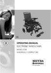


![e-track User`s Manual [FW1.00]](http://vs1.manualzilla.com/store/data/005696177_1-79f2a7130a6208690505d356432cfe5f-150x150.png)