1
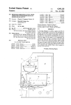
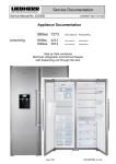
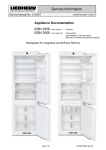
Service Documentation After Sales Service International Service Manual No. 13/2011 LWL/KDT/baj/09.05.11 Appliance Documentation ECN 6156 from Index 20 NoFrost fridge-freezer combination 91cm wide (refrigerator compartment with LargeDoor – freezer compartment with pull-out drawers) Page 1/39 13201100SM_gb.doc Service Manual No. 13/2011 ECN 6156 Contents 1.0 2.0 3.0 3.1 3.2 4.0 4.1 Operating and control elements ............................................................................................. 3 Functions at a glance .............................................................................................................. 4 Description of the appliance................................................................................................... 5 Sensor positions, schematic diagram ........................................................................................ 6 Plinth design, schematic diagram .............................................................................................. 6 Main components and their functions ................................................................................... 7 Electrical components and functions ......................................................................................... 7 4.1.1 General .................................................................................................................................................. 7 4.1.2 Refrigerator compartment ..................................................................................................................... 7 4.1.3 Freezer compartment ............................................................................................................................ 9 4.2 Refrigeration components and functions ................................................................................. 11 4.2.1 General ................................................................................................................................................ 11 4.2.2 Refrigerator compartment ................................................................................................................... 11 4.2.3 Freezer compartment .......................................................................................................................... 11 5.0 Assembly instructions / replacement of parts .................................................................... 12 5.1 General ................................................................................................................................... 12 5.1.1 Control panel electronics ..................................................................................................................... 12 5.1.2 Power electronics ................................................................................................................................ 13 5.1.3 Condenser fan ..................................................................................................................................... 15 5.2 Refrigerator compartment........................................................................................................ 16 5.2.1 Replacing door .................................................................................................................................... 16 5.2.2 Hinge replacement .............................................................................................................................. 17 5.2.3 Soft-close mechanism replacement .................................................................................................... 18 5.2.4 Heating of hinge housing ..................................................................................................................... 18 5.2.5 Dismantling the refrigerator compartment evaporator cover ............................................................... 19 5.2.6 Replace mount for water filter ............................................................................................................. 19 5.2.7 Refrigerator compartment air sensor .................................................................................................. 21 5.2.8 Refrigerator compartment evaporator sensor ..................................................................................... 21 5.2.9 Refrigerator compartment fan ............................................................................................................. 22 5.2.10 Fitting the cover ................................................................................................................................... 22 5.3 Freezer compartment .............................................................................................................. 23 5.3.1 5.3.2 5.3.3 5.3.4 5.3.5 5.3.6 5.3.7 5.3.8 6.0 6.1 6.2 6.3 7.0 8.0 8.1 8.2 8.3 8.4 Dismantling the freezer compartment drawers ................................................................................... 23 Freezer compartment evaporator cover .............................................................................................. 24 Freezer compartment air sensor ......................................................................................................... 25 Temperature limiter ............................................................................................................................. 25 Evaporator sensor, freezer compartment ............................................................................................ 26 Freezer compartment fan .................................................................................................................... 27 Freezer compartment reed contact ..................................................................................................... 28 Fitting the cover ................................................................................................................................... 29 Technical data ....................................................................................................................... 30 General ................................................................................................................................... 30 Refrigerator compartment........................................................................................................ 30 Freezer compartment .............................................................................................................. 30 Customer menu ..................................................................................................................... 31 Service menu ......................................................................................................................... 32 Manual defrosting .................................................................................................................... 32 Demo mode ............................................................................................................................. 33 Panel test ................................................................................................................................ 34 Sensor test (display of temperature) and door contact test...................................................... 35 8.4.1 Refrigerator/freezer compartment ....................................................................................................... 35 8.4.2 IceMaker.............................................................................................................................................. 36 8.5 Service mode .......................................................................................................................... 37 8.5.1 Refrigerator/freezer compartment ....................................................................................................... 37 8.5.2 IceMaker.............................................................................................................................................. 38 8.5.3 Solenoid valve 9.0 ............................................................................................................................. 39 Error codes ............................................................................................................................ 39 Page 2/39 Service Manual No. 13/2011 ECN 6156 1.0 Operating and control elements 10 1 2 3 4 11 15 12 16 13 17 14 18 5 6 7 8 9 22 21 19 20 23 Control elements: 1 2 3 4 10 Refrigerator compartment SuperCool SuperCool function ON/OFF ON/OFF button for refrigerator compartment Up Setting button temperature higher Down Setting button temperature lower Alarm 5 6 7 8 9 General Alarm OFF button for audible alarm Freezer compartment Setting button temperature higher Down Setting button temperature lower ON/OFF ON/OFF button for freezer compartment SuperFrost SuperFrost function IceMaker ON/OFF button for IceMaker Up Control elements: 11 12 13 14 15 16 17 18 Front panel Power failure Clean dust filter (plinth) SuperCool activated Child lock activated Alarm IceMaker switched ON Inactive SuperFrost activated 19 20 21 22 23 Page 3/39 MagicEye Replace water filter Customer menu activated Temperature display in °C Refrigerator compartment temperature Freezer compartment temperature Service Manual No. 13/2011 ECN 6156 2.0 Functions at a glance Control: Electronic Temperature display: Refrigerator compartment: Freezer compartment: Actual value Actual value Temperature range: Refrigerator compartment: Freezer compartment: +2°C to +11°C -14°C to -28°C Temperature alarm: Refrigerator compartment: Freezer compartment: Not present Visual, audible Door alarm: Refrigerator compartment: Freezer compartment: Audible Audible Fan: Refrigerator compartment: Freezer compartment: Present Present Defrosting: Refrigerator compartment: Freezer compartment: Automatic Automatic Interior lighting: Refrigerator compartment: Freezer compartment: Present Present Service menu: Present Compressor: 2x Standard Solenoid valve refrigeration circuit: Not present Page 4/39 Service Manual No. 13/2011 ECN 6156 3.0 Description of the appliance The ECN is a fridge-freezer combination with a freely suspended rear wall evaporator in the refrigerator compartment and a NoFrost freezer compartment with IceMaker. The temperature in the refrigerator compartment is controlled by an air sensor and an evaporator sensor. The temperature in the freezer compartment is also controlled by an air sensor. The defrosting phases are initiated by way of the electronic control system, taking compressor running time and door openings into account. The appliance has 2 compressors. Therefore the refrigerator compartment and freezer compartment have a separate refrigeration circuit and can be controlled separately. Page 5/39 Service Manual No. 13/2011 3.1 ECN 6156 Sensor positions, schematic diagram Front panel with PCB and reed contact Refrigerator compartment air sensor Refrigerator compartment evaporator sensor Cover for refrigerator compartment evaporator Freezer compartment air sensor Freezer compartment evaporator sensor Condenser Power PCB Fig. 3.1 / 1 3.2 Fig. 3.1/ 2 Plinth design, schematic diagram Refrigerator compartment compressor Freezer compartment compressor Power electronics Condenser fan Filter Page 6/39 Service Manual No. 13/2011 ECN 6156 4.0 Main components and their functions 4.1 Electrical components and functions 4.1.1 General Electronics Type: Series 6 electronic control system Components: Control panel and power PCB Compressor Type: 2 standard compressors Function-refrigerator compartment: ON: Refrigerator compartment evaporator sensor switch-on value. Note: On-delay time (8 minutes) must have elapsed. OFF: Refrigerator compartment air sensor switch-off value ON: Freezer compartment air sensor switch-on value Note: On-delay time (8 minutes) must have elapsed. OFF: Freezer compartment air sensor switch-off value Function-freezer compartment: Condenser fan Position: In the appliance plinth Function: ON: Refrigeration compartment compressor ON Freezer compartment compressor ON OFF: Both compressors OFF or 4.1.2 Refrigerator compartment Electronics Setting range: +2°C to +11°C Display range: 0°C to +48°C (actual value display) Temperatures equal to and lower than +0°C are displayed as 0. Functions SuperCool: SuperCool ON: Refrigerator compartment sets itself to +2°C for 6 hours. SuperCool OFF: The refrigerator compartment sets itself to the set value. Defrosting: Automatic during compressor standstill phase. Door alarm: When: After the door has been open for 1 minute. Audible: 3 beeps. Page 7/39 Service Manual No. 13/2011 ECN 6156 Sensors Refrigerator compartment air sensor: Position: In the vertical cover. Function: - Switches the refrigerator compartment compressor OFF. - Generates the refrigerator compartment temperature display value. Evaporator sensor: Position: In sensor holder on the back of the evaporator. Function: - Switches the refrigerator compartment compressor ON. - Ends the defrosting phase. Position: In the front panel. Type: Tube-type reed Switch Door switch: Contact type: Make contact Function: Activation via: Magnet on both doors, magnet is replaceable. Switching signal when: Doors closed: fan interior light ON OFF Doors open: OFF ON ON after 60 seconds fan interior light door alarm Loads Fan: Position: on the back of the evaporator cover. Function: ON: - compressor ON and - freezer compartment door closed and - during commissioning compressor sensor switch-on value (+8°C) reached. OFF: - Compressor OFF Refrigerator compartment interior light: Position: On the ceiling, on the right and left side of interior Function: - Shines as soon as the door is opened. - Is switched OFF after door has been open for 15 minutes. Heating for hinge housing: Position: Glued and foamed-in on the back of the two bottom hinge housings (left and right). Function: Can be activated when condensate collects. Page 8/39 Service Manual No. 13/2011 ECN 6156 4.1.3 Freezer compartment Electronics Setting range: -14°C to -28°C Display range: +0°C to -50°C (actual value display) values over +0°C are indicated on bar display. Functions Temperature alarm: Alarm value: 4K warmer than set value. SuperFrost alarm value: -10°C Delay: 20 minutes Visual: Flashing temperature display. Audible: 4 beeps. During start-up: The temperature display flashes until the switch-off value is reached, the audible alarm is switched OFF. (e.g. with a set value of 0°C, a temperature of +7°C must be present for at least 20 minutes, then a temperature alarm is raised.) After the defrosting phase begins, the temperature alarm is suppressed for 1.5 hrs. Defrosting: The defrosting phase is initiated: - During start-up after 6 hours cumulative compressor running time. - After a cumulative compressor running time of 15 to 24 hours maximum, depending on the number/duration of the door openings. As the defrosting phase begins, the compressor and fan are switched OFF and the defrost heater is switched ON. The defrost heater remains switched ON until such time as - the freezer compartment evaporator sensor has reached +5°C or - a max. defrosting time of 50 minutes has been reached. After the end of the heating phase, the compressor is switched on with a 5 minute delay. If the SuperFrost function is activated during the defrosting phase, this will not interrupt defrosting. Door alarm: SuperFrost: When: After the door has been open for 1 minute. Audible: 3 beeps. SuperFrost ON: Refrigerator compartment sets itself to -34°C for 30 hours. In the following 35 hours SuperFrost is ended automatically after the temperature falls 8K below the set value (at -18°C -> -26°C) or on expiry of the total period of 65 hours. SuperFrost OFF: The freezer compartment sets itself to the set value. Attention: If SuperFrost is actuated during a defrosting phase, the SuperFrost function is not performed before the defrosting phase has run. Page 9/39 Service Manual No. 13/2011 ECN 6156 Sensors Air sensor: Evaporator sensor: Position: On the front of the evaporator cover Function: - Switches the freezer compartment compressor ON. - Switches the freezer compartment compressor OFF. - Freezer compartment air sensor and freezer compartment evaporator sensor switch the freezer compartment fan ON. - Generates the freezer compartment temperature display value. Position: Slipped in, in the lower area of the lamellar evaporator. Function: - Freezer compartment evaporator sensor and freezer compartment air sensor switch the freezer compartment fan ON. - Ends the defrosting phase. Position: On the back of the freezer compartment evaporator cover. Type: 2x reed PCB Switch Door switch: Contact type: Make contact Function: Activation via: Magnet in back right corner of the drawers. Magnet is replaceable. Switching signal when: door closed: fan interior light ON OFF door open: fan interior light door alarm OFF ON ON after 60 seconds Loads Fan: Position: Top centre of freezer compartment. Function: ON: - compressor ON and - freezer compartment door closed and - evaporator sensor switch-on value reached. Switch-on value evaporator sensor: a) during start-up / after defrosting phase: -20°C. b) During normal operation 2K colder than freezer compartment air sensor. OFF: Defrost heater: Interior light: - Compressor OFF Position: Clipped into lamellar evaporator. Function: Defrosts the evaporator. For activation, see: Functions Defrosting Position: On the ceiling and in the cross ridge. Function: - Shines as soon as the door is opened. - Is switched OFF after door has been open for 15 minutes. Page 10/39 Service Manual No. 13/2011 4.2 ECN 6156 Refrigeration components and functions 4.2.1 General Compressor Compressor: 2 x Standard Refrigerant: R600a 4.2.2 Refrigerator compartment Evaporator Type: Plate evaporator Type of installation: Suspended freely. Injection point: At the top left 4.2.3 Freezer compartment Evaporator Type: Lamellar evaporator Type of installation: Freestanding between air duct panel and compartment liner. Injection point: Top centre Page 11/39 Service Manual No. 13/2011 ECN 6156 5.0 Assembly instructions / replacement of parts 5.1 General 5.1.1 Control panel electronics Covers: - Disengage the covers at the marked locations. Fig. 5.1.1 / 1 Front panel: - Unclip the front panel at the left and right. Fig. 5.1.1 / 2 PCB carrier: - Disengage and remove bus connector. Note: Front panel can only be replaced as a whole, PCB and reed contact are not available separately! Tube-type reed Fig. 5.1.1/ 3 Page 12/39 Service Manual No. 13/2011 ECN 6156 5.1.2 Power electronics Aggregate housing: - Remove ventilation grille. - Unclip cover at two points on the bottom and remove fastening screw. - Then hinge up the cover as far as it will go until the lug can be unclipped at the top. Clip Cover Fastening screw Fig. 5.1.2 / 1 Cable mounting bracket: Fig. 5.1.2/ 2 - Unclip the cable mounting bracket at the marked location and unscrew the strain relief. - Detach front PCB edge connectors. Fig. 5.1.2/ 3 Page 13/39 Service Manual No. 13/2011 PCB carrier: ECN 6156 - Unclip the PCB carrier at the left and right and draw it out of the unit carrier. - Detach feed line and rear PCB edge connectors (sensors, reed, contact bus line). Fig. 5.1.2/ 4 Electronic power module: - Disengage the upper part of the plug-in unit at the marked locking hooks and remove it. - Disengage the PCB at the marked locations. Fig. 5.1.2/ 5 Fig. 5.1.2/ 6 Page 14/39 Service Manual No. 13/2011 ECN 6156 5.1.3 Condenser fan Dismantling: - Remove the ventilation grille and dust filter. - Remove marked retaining lugs at the same time and pull out fan mount and motor from the intake funnel. - Electrical connection is by means of a rigid plug-in connector. Plug-in connector Fig. 5.1.3/ 1 Fan mount: Fig. 5.1.3/ 3 Fig. 5.1.3/ 2 - Remove blades from axle (possibly first remove casing). - Unclip the fan motor from the mount. Fig. 5.1.3/ 4 Page 15/39 Service Manual No. 13/2011 5.2 ECN 6156 Refrigerator compartment 5.2.1 Replacing door Disassembling the door Remove fastening screws and take off door. Note: When closed, the door is held to a certain extent by the effect of the magnet door seal. Support the door anyway for safety sake or hold while removing the screws. Fig. 5.2.1/ 2 Fig. 5.2.1/ 1 Adjust door: Fig. 5.2.1/ 3 - Loosen fastening screws a little. - With the help of the set screw on the respective mounting bracket the door can be adjusted in relation to the hinge and thus the appliance body. - Retighten the fastening screws afterwards. Set screw Set screw Fig. 5.2.1/ 4 Fig. 5.2.1/ 5 Set screw Set screw Fig. 5.2.1/ 6 Fig. 5.2.1/ 7 Page 16/39 Service Manual No. 13/2011 ECN 6156 5.2.2 Hinge replacement Hinge: Remove fastening screws and hinge. On the outside, the hinge is hooked into the housing with two lugs. Note: By inserting a safety bolt, the hinge can be protected against snapping shut. Recesses for lugs Fig. 5.2.2 / 2 Hinge Lugs Fig. 5.2.2/ 1 Holder for retaining device or limiting pin Hinge Fig. 5.2.2/ 3 Tighten hinge: To achieve the correct closing force, once the new hinge and door are mounted, the new hinge must be tightened. Note: Turn tensioning screw to stop – not just until screw head is in I-position. Fig. 5.2.2/ 4 Not tensioned Fig. 5.2.2/ 5 tensioned Fig. 5.2.2/ 6 Page 17/39 Service Manual No. 13/2011 ECN 6156 5.2.3 Soft-close mechanism replacement To prevent the door from slamming shut, two soft-close mechanisms are installed in each hinge housing. They are inserted in the recesses and can be pulled out again. Soft-close assembled Soft-close disassembled Fig. 5.2.3/ 2 Fig. 5.2.3 / 1 5.2.4 Heating of hinge housing To prevent condensation forming on the inside of the lower hinge housings, they are heated using a foamed-in heating system. Heating activation is described in chapter 7.0. Hinge housing Fig. 5.2.6 / 1 Page 18/39 Service Manual No. 13/2011 ECN 6156 5.2.5 Dismantling the refrigerator compartment evaporator cover Refrigerator compartment evaporator cover: - Remove 7 screws, release bayonet lock, screw out water filter. - First pull cover down a little and then swivel up. - Unplug fan cable, remove air sensor from mount and remove cover. Water filter Cover Air sensor Fig. 5.2.7 / 1 5.2.6 Replace mount for water filter Mount for water filter: - The mount is fixed behind the evaporator cover on the appliance rear wall. - Remove putty on the back and evenly cut water hoses approx. 10cm below the bushing. Holder Fig. 5.2.8/ 1 Fig. 5.2.8/ 2 Page 19/39 Service Manual No. 13/2011 Connecting water hoses: ECN 6156 - Hose ends must be inserted into the connector by 17mm respectively (mark as required). ATTENTION: Do not mix up the hose ends. Water must flow through the filter in the specified direction. - Check for firm seating and attach a circlip at either end (this stops the lock loosening). - Fill hoses and check for leakage (use test program for IceMaker, allow water to run). Marking Fig. 5.2.8/ 3 Circlip Fig. 5.2.8/ 4 Fig. 5.2.8/ 5 Page 20/39 Service Manual No. 13/2011 ECN 6156 5.2.7 Refrigerator compartment air sensor Refrigerator compartment air sensor: - Remove styropor cover from the air sensor mount and pull out sensor. - Pull out the air sensor through the back of the appliance feedthrough and replace using the repair kit. The repair instructions accompany the repair kit. Cover for air sensor Air sensor Fig. 5.2.9/ 1 Fig. 5.2.9/ 2 5.2.8 Refrigerator compartment evaporator sensor Refrigerator compartment evaporator sensor: - 4 Remove bayonet screws. - Swing the evaporator to the left. Pull the sensor out of the mount. - Pull out the evaporator sensor through the back of the appliance feedthrough and replace using the repair kit. The repair instructions accompany the repair kit. Evaporator sensor Fig. 5.2.10/ 1 Fig. 5.2.10/ 2 Page 21/39 Service Manual No. 13/2011 ECN 6156 5.2.9 Refrigerator compartment fan Refrigerator compartment fan: - Unclip the fan together with the absorber ring. - Pull the fan out of the absorber ring. Absorber ring Fig. 5.2.11/ 1 Fig. 5.2.11/ 2 5.2.10 Fitting the cover Fitting: - Push the retaining lug of the cover into the grooves of the compartment liner. - Screw on cover. Retaining lug Holder for capacitors Fig. 5.2.12/ 1 Fig. 5.2.12/ 2 Page 22/39 Service Manual No. 13/2011 5.3 ECN 6156 Freezer compartment 5.3.1 Dismantling the freezer compartment drawers Remove insert: 2. - Lift insert by approx. 2 cm at the front and then push back to unclip it at the rear. - Lift the insert up and out of the drawer. 1. Fig. 5.3.1/ 1 Remove drawer: - Remove fastening screws on the left and right rails. - Unclip rails from the rear locking pins and remove the drawer. - Please note position of the adjusting aids at the front (important for assembly). Adjusting aid Fig. 5.3.1/ 2 Page 23/39 Service Manual No. 13/2011 ECN 6156 5.3.2 Freezer compartment evaporator cover IceMaker: - Press up the locating lugs of the IceMaker and draw the IceMaker forwards. - Disconnect cables. Retaining lug Fig. 5.3.2/ 1 Cover: Fig. 5.3.2/ 2 - Unclip the air sensor and remove the four screws. - Draw the cover forwards and swing it out at the bottom. - Disconnect the connecting cable to the reed contacts and remove the cover Cable for reed PCB Air sensor Fig. 5.3.2/ 3 Fig. 5.3.2/ 4 Page 24/39 Service Manual No. 13/2011 ECN 6156 5.3.3 Freezer compartment air sensor Air sensor: - Pull the air sensor out rearwardly through the housing feedthrough and replace it by the repair kit. The repair instructions accompany the repair kit. Air sensor Fig. 5.3.3/ 1 5.3.4 Temperature limiter Temperature limiter: - Unscrew the temperature limiter. - Detach the sheeting. - Lift out the temperature limiter. - The new temperature limiter is put together using the repair kit. Fig. 5.3.4 / 1 Page 25/39 Service Manual No. 13/2011 ECN 6156 5.3.5 Evaporator sensor, freezer compartment Evaporator sensor: Raise evaporator module and swing it out in a forward direction. - Make incisions in the sheeting at the marked locations (1st and 2nd step, see Fig. 5.3.5/ 1 and Fig. 5.3.5/ 2). - Bend open the retaining lugs of the cover plate and remove it. - Draw the evaporator sensor to the left, out of the lamellar evaporator. - Pull the sensor out through the back of the appliance feedthrough and replace using the repair kit. The repair instructions accompany the repair kit. Defrost heater: Is clipped into the evaporator fins. Can be replaced if defective. 1st step Fig. 5.3.5/ 1 Making an incision in the sheeting 2nd step 3rd step Defrost heater Evaporator sensor Fig. 5.3.5/ 2 Cutting open the evaporator cover Fig. 5.3.5/ 3 Lamellar evaporator Page 26/39 Service Manual No. 13/2011 ECN 6156 5.3.6 Freezer compartment fan Freezer compartment fan: - Disconnect fan cable. - Remove the fastening screws and detach the fan together with the mount. - Remove the blades and strip off the rubber rings. - Disengage the locating lugs and remove the bracket of the mount. Fig. 5.3.6/ 1 Fig. 5.3.6/ 2 Page 27/39 Service Manual No. 13/2011 ECN 6156 5.3.7 Freezer compartment reed contact Reed PCB: - Remove the polystyrene strip on the back of the freezer compartment evaporator cover. - Remove the reed PCB from the mount and disconnect it. Reed PCB for upper drawer Reed PCB for lower drawer Fig. 5.3.7/ 1 Fig. 5.3.7/ 2 Position of the reed contacts: - On the evaporator cover. Position of the magnets: - In back right corner of the drawers. Magnet Reed contact lower drawer Reed contact lower drawer Fig. 5.3.7/ 3 Fig. 5.3.7/ 4 Page 28/39 Service Manual No. 13/2011 ECN 6156 5.3.8 Fitting the cover Cover: - Air ducts must be free from cables. - Therefore stow away the air sensor cables and reed PCB cables in the space above the evaporator. - The cover must rest completely against the compartment liner so that proper air circulation is maintained. - Please ensure that the cover also rests on the compartment liner ceiling so that the bottom drawer can slide into end position on closing. Air ducts Fig. 5.3.8/ 1 Fig. 5.3.8/ 2 Fig. 5.3.8/ 3 Fig. 5.3.8/ 4 Page 29/39 Service Manual No. 13/2011 ECN 6156 6.0 Technical data 6.1 General Sensor values: 6.2 Temperature [°C] Resistance value [kOhm] +35 +30 +25 +20 +15 +10 +5 0 -5 -10 -15 -20 -25 -30 -35 3.1 3.8 4.7 5.9 7.4 9.4 11.9 15.4 19.9 26.0 34.3 45.7 61.4 83.4 114.5 Refrigerator compartment Interior light Light column: Wattage: voltage: 2 x 2.86 W approx. 13 V/DC , with LED light connected. 4 LEDs: Wattage: voltage: 4 x 1.1 W approx. 18 to 20 V/DC , with LED light connected. Vegetable drawers: Wattage: 2 x 2.86 W voltage: approx. 18 to 20 V/DC , with LED light connected. In total: 13,4 W Fan: Wattage: Voltage: 1,1 W 11 V/DC Heating for hinge housing: Wattage: voltage: approx. 12 W 24 V/DC 6.3 Freezer compartment Interior light 2 strips with 2 LEDs each: Wattage: 4 x approx. 1.1 W Voltage: approx. 18-20 V/DC, with connected LED lighting. In total: 4.4 W Fan: Wattage: Voltage: 4.5 W 230 V/AC Defrost heater: Wattage: Voltage: 194 W 230 V/AC Temperature fuse: Tripping temperature: +84°C (is defective after it has been tripped and has to be replaced) Page 30/39 Service Manual No. 13/2011 ECN 6156 7.0 Customer menu Customer menu activation: Press "SuperFrost" for approx. 5 seconds. All the functions that can be set and activated by the customer (e.g. display brightness, child lock,...) are described in the operating instructions. Only the permanent activation of heating for the bottom hinge housing is no longer described in the operating manual: If, due to major condensate formation in the hinge housing, the heating should be permanently activated, state HI must be assigned a new heating activation period (HH): - Press the SuperFrost symbol for 5 seconds -> customer menu open - Press the Down symbol for the freezer compartment until H appears in the display - Press SuperFrost symbol -> HA is indicated in the display - Press the Up symbol for 4 seconds -> HH is indicated in the display - Press SuperFrost symbol -> H is indicated in the display - Press SuperFrost symbol -> HA is indicated in the display - Press the Up symbol for the freezer compartment until HI appears in the display - Press SuperFrost symbol -> H is indicated in the display - Press On/Off symbol for the freezer compartment -> customer menu closed Until now New Activation period for HI HO Permanently OFF Permanently OFF HA 20" ON / 40" OFF 20" ON / 40" OFF HI Permanently ON 20" ON / 40" OFF HL (as standard) Permanently ON HH The original heater activation period (HL) can be re-assigned to the HI state at a later stage (e.g. when the ambient humidity has returned to a lower level): - Press the SuperFrost symbol for 5 seconds -> customer menu open - Press the Down symbol for the freezer compartment until H appears in the display - Press SuperFrost symbol drücken -> HI is indicated in the display - Press the Down symbol for 4 seconds -> HL is indicated in the display - Press SuperFrost symbol -> H is indicated in the display - Press the ON/OFF symbol for the freezer compartment -> customer menu closed Page 31/39 Service Manual No. 13/2011 ECN 6156 8.0 Service menu The service menu may be used by service technicians only. Activation of service menu: Press "Up" + "ON/OFF" simultaneously for about 5 seconds (freezer compartment buttons) Once the service menu is activated, "MENU" flashes in the display. 8.1 Manual defrosting Step Display Operation Display following operation Service menu start 1 Actual value 2 SF = SuperFrost Press "Up" and "ON/OFF" simultaneously for 5 seconds flashes flashes static static Manual defrosting ON activated Press "SF" once static Manual defrosting is ended by: - Switching appliance OFF/ON - Automatic after the defrost parameters are reached Page 32/39 Service menu active, Manual defrosting selected Manual defrosting ON selected Press "SF" once 3 Testing option / Info Service Manual No. 13/2011 8.2 ECN 6156 Demo mode Step Display Operation Display following operation SF = SuperFrost Start service menu -- Demo mode ON -1 Actual value 2 Press "Up" and "ON/OFF" simultaneously for 5 seconds flashes Service menu active flashes Demo mode selected static Demo mode ON selected Press "Up" once flashes 3 Press "SF" once flashes 4 Press "SF" once static Set value and "Demo" Actual value and "Demo" 2 Press "Up" and "ON/OFF" simultaneously for 5 seconds flashes and "Demo" Service menu active flashes and "Demo" Demo mode selected static and "Demo" Demo mode OFF selected Actual value Demo mode OFF Press "Up" once flashes 3 Press "SF" once flashes and "Demo" 4 Demo mode ON SF = SuperFrost Start service menu --Demo mode OFF-1 Testing option / Info Press "SF" once static and "Demo" The text "Demo" in the display informs of the activated demo mode. Demo mode can be deactivated only via service menu, not by OFF/ON or disconnection from the supply. Operation switches to the mode wanted, demo mode or normal mode, as soon as "SuperFrost" has been actuated. Page 33/39 Service Manual No. 13/2011 8.3 ECN 6156 Panel test Step Display Operation Display following operation Service menu start 1 Actual value Testing option / Info SF = SuperFrost Press "Up" and "ON/OFF" simultaneously for 5 seconds flashes Service menu active Panel test -- test of sensor buttons, display elements, door sensor and beep -2 Press "Up" twice flashes 3 Panel test selected flashes Press "SF" once flashes 4 static Press "SF" once All symbols/segments Panel test activated All symbols/segments static 5 End All symbols/segments Doors closed/open and - Beep for 2 sec. press all buttons one after - appliance switches the other OFF (each operation is confirmed by a beep) After the last button has been pressed a beep sounds for 2 seconds, only if the test has been successful. Panel test cannot be ended in step 2, for example, it has to be performed in full. Should a button/sensor be defective, there will be no 2-second beep and the appliance will not switch OFF. The appliance then has to be unplugged and plugged back in again. Page 34/39 Service Manual No. 13/2011 8.4 ECN 6156 Sensor test (display of temperature) and door contact test 8.4.1 Refrigerator/freezer compartment Step Display Operation Display following operation Testing option / Info Service menu start 1 Actual value SF = SuperFrost Press "Up" and "ON/OFF" simultaneously for 5 seconds flashes Service menu active Sensor test and door contact test (sensor values without offset, appliance in control mode) 2 flashes 3 4 Press "SF" once flashes alternately with sensor temperature flashes alternately with sensor temperature Press "Up" once flashes alternately with sensor temperature flashes alternately with sensor temperature Press "Up" once flashes alternately with sensor temperature Press "Up" once static 6 7 8 9 End static Sensor test mode activated Press "SF" once flashes 5 flashes Sensor test mode selected Press "Up" three times flashes alternately with sensor temperature flashes alternately with sensor temperature Press "Up" once Freezer compartment evaporator sensor flashes alternately with sensor temperature Refrigerator compartment air sensor flashes alternately with sensor temperature Refrigerator compartment evaporator sensor flashes alternately with k Press "Up" once Freezer compartment air sensor or flashes alternately with k or Refrigerator compartment door contact (cL=door closed, oP=door open) Freezer compartment door contact(cL=door closed, oP=door open) Press "ON/OFF" once: Return to level 2 . No further points selectable with this appliance. Press "ON/OFF" twice: Return to level 1 . Points: , , , selectable Press "ON/OFF" three times: Return to normal/control mode Page 35/39 Service Manual No. 13/2011 ECN 6156 8.4.2 IceMaker Step Display Operation Display following operation Testing option / Info Service menu start 1 Actual value SF = SuperFrost Press "Up" and "ON/OFF" simultaneously for 5 seconds Service menu active flashes Sensor test and door contact test (sensor values without offset, appliance in control mode) 2 flashes 3 4 Press "Up" once static 56 End static Sensor test mode activated Press "SF" once flashes 65 flashes Sensor test mode selected Press "Up" three times static flashes alternately with sensor temperature Press "SF" once Press "Up" once IceMaker selected static flashes alternately with sensor temperature flashes alternately with k or IceMaker air sensor Ice-cube drawer door contact (oP=door open, cL=door closed) Press "ON/OFF" once: Return to level 2 . No further points selectable with this appliance. Press "ON/OFF" twice: Return to level 1 . Points: , , , selectable Press "ON/OFF" three times: Return to normal/control mode Page 36/39 Service Manual No. 13/2011 8.5 ECN 6156 Service mode 8.5.1 Refrigerator/freezer compartment Step Display Operation Display following Testing option / Info operation Service menu start 1 Actual value SF = SuperFrost Press "Up" and "ON/OFF" simultaneously for 5 flashes seconds Service menu active Service mode -- testing electric loads-- 2 flashes 3 Press "Up" four times Service mode selected flashes Press "SF" once flashes 4 Service mode activated static Press "SF" once static 145 All OFF static Freezer compartment compressor ON --- static Refrigerator compartment compressor ON --- static Freezer compartment fan ON 4.5 W static Freezer compartment defrost heater ON 194 W static Refrigerator compartment light ON 19 W static Refrigerator compartment fan ON 5.5 W Freezer compartment light ON 8.5 W Condenser fan ON 4.5 W Hinge heating ON 12 watts Press "Up" once static 6 Press "Up" once static 7 Press "Up" once static 8 Press "Up" once static 9 Press "Up" once static 10 Press "Up" once static 11 static Press "Up" once static 12 static Press "Up" once static 13 static Press "Up" once static 5 14 static Press "Up" once static End Power input Return to step 5 static Press "ON/OFF" once: Return to level 2 . Points: Press "ON/OFF" twice: Return to normal/control mode Page 37/39 , , , selectable Service Manual No. 13/2011 ECN 6156 8.5.2 IceMaker Step Display Operation Display following operation Testing option / Info Service menu start 1 Actual value SF = SuperFrost Press "Up" and "ON/OFF" simultaneously for 5 flashes seconds Service menu active Service mode -- testing electric loads-2 Press "Up" four times flashes 3 Service mode selected flashes Press "SF" once flashes 4 Service mode activated static Press "Up" once static 5 IceMaker selected static Press "SF" once static 12 6 All OFF static Press "Up" once flashes alternately with static All OFF - ice cube tray emptied, back to home position - 3 sec. solenoid valve ON 7 flashes alternately with Press "SF" once flashes alternately with 8 flashes alternately with Press IceMaker ON/OFF button flashes alternately with All OFF 9 flashes alternately with Press "Up" once flashes alternately with All OFF 10 flashes alternately with Press "SF" once - ice cube tray emptied - 25 sec. solenoid valve ON After 25 seconds have elapsed, flashes alternately with flashes alternately with again The drawer must be closed at the time! 11 flashes alternately with 6 12 flashes alternately with End - Press IceMaker ON/OFF button ( switch ON) - Close drawer flashes alternately with Ice cube tray returns to home position Press "Up" once Return to step 6 static Press "ON/OFF" once: Return to level 2 : Items: Press "ON/OFF" twice: Return to normal/control mode Page 38/39 , , selectable Service Manual No. 13/2011 ECN 6156 8.5.3 Solenoid valve Step Display Operation Display following operation Testing option / Info Service menu start 1 SF = SuperFrost Actual value Press "Up" and "ON/OFF" simultaneously for 5 seconds Service menu active flashes Service mode -- testing electric loads-2 Press "Up" four times flashes Service mode selected flashes 3 Press "SF" once flashes Service mode activated static 4 Press "Up" once static IceMaker selected static Press "Up" once 5 static Solenoid valve selected static 6 Press "SF" once All OFF Press "Up" once flashes All OFF alternately with static 97 static 8 flashes Press "SF" once alternately with - 10 seconds solenoid valve ON flashes alternately After the 10 seconds have elapsed, with flashes alternately with 79 flashes Press "Up" once alternately with static End Return to step 6 Press "ON/OFF" once: Return to level 2 : Items: Press "ON/OFF" twice: Return to normal/control mode , , selectable 9.0 Error codes Error code Defective component Emergency mode F1 Refrigerator compartment air sensor Compressor 20 minutes ON and 40 minutes OFF. F2 Refrigerator compartment evaporator sensor Compressor 20 minutes ON and 40 minutes OFF. F3 Freezer compartment air sensor Compressor continuous operation F4 Freezer compartment evaporator sensor Compressor continuous operation Page 39/39