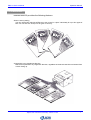
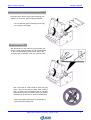
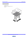
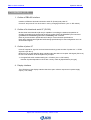
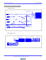
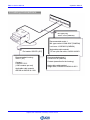
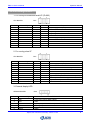
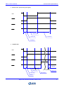
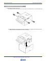
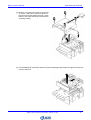
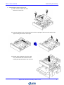
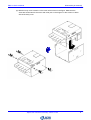
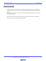
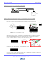
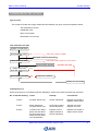
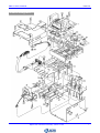
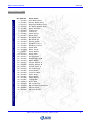
1
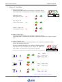
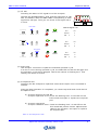
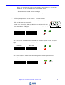
Europe Bill Acceptor
EBA-03
Service Manual
Copyright © 2002JAPAN CASH MACHINE GERMANY GmbH
Copyright © 2002 Japan Cash Machine Germany GmbH
Europe Bill Acceptor
EBA-03
Model Numbers
Copyright © 2002 Japan Cash Machine Germany GmbH
EBA-03 Service Manual
Model Numbers
Contents
EBA Product Name …...........……….………..……….……………………………………………….
Japan Cash Machine Germany GmbH 2002
Page
1
Contents
EBA-03 Service Manual
Model Numbers
EBA Product Name
EBA product name constitutes two kinds, it is [MODEL] name and [TYPE] name.
EBA – 03 – ∗∗∗ – ∗∗∗ – ∗∗∗
[MODEL] name
[TYPE] name
[MODEL]
EBA-03
[Type]
∗ ∗ ∗ – ∗ ∗ ∗ – 03
1
2
3
1
With/without I/F conversion board (future support)
0 : Without I/F conversion board
1 : With I/F conversion board
2
With/without faceplate (future support
0 : No faceplate
1 : With faceplate
3
Reserved
Japan Cash Machine Germany GmbH 2002
1
Europe Bill Acceptor
EBA-03
Operation Manual
Copyright © 2002 Japan Cash Machine Germany GmbH
EBA-03 Service Manual
Operation Manual
Contents
1
2
3
4
5
6
7
8
9
10
11
12
13
14
Page
Features …………………….…………………………………………………………………….
1
Names of Parts ……..…………………..…….…………………………………………………
2
Precautions ………………………….……………………………………………………………
2
Removing a Jammed Bill ……………………………………………………………………….
3
Cleaning …………………………………………………………………………………………..
3
Installation ………………………………………………………………………………………
4
Interface (I/F) ..……………………………………………………………………………………
5
Input/Output Circuits …………………………………………………………………………….
6
Cabling Connections …………………………………………………………………………….
7
Pin Assignment …………………………………………………………………………………..
8
Description of DIP Switch ……...……………………………………………………………….
9
Operation Flowchart …………………………………………………………………………….. 10
General Specifications (WS Model) ………..…….…………………....……………………… 12
Outside Dimensions ………………………………………....………………………………….. 13
Japan Cash Machine Germany GmbH 2002
Contents
EBA-03 Service Manual
Operation Manual
1 Features
Validator EBA-03 provides the following features.
Allows currency setting
You can use the DIP switches of EBA-03 to set “accept” or “reject” individually for up to four types of
bills. You can also set “accept” for all types of currency.
Accepts bills in any lengthwise direction
EBA-03 accepts bills in any lengthwise direction, regardless of whether these bills are inserted front
or back facing up.
Japan Cash Machine Germany GmbH 2002
1
EBA-03 Service Manual
Operation Manual
2 Names of Parts
Interface connector
Open/close button for upper scanning unit
ROM maintenance cover
Upper scanning unit
DIP switch
Bill insertion slot
LED
Hinge
Interface connector
3 Precautions
1. Don not insert a torn, folded,
or wet bill. It will get jammed
in the unit.
2. Never spill water or any liquid
on the unit. The precision electronic parts in the unit will be
damaged.
Japan Cash Machine Germany GmbH 2002
3. Do not install the unit in a dusty
environment. Dust will affect
the performance of the bill
sensor.
2
EBA-03 Service Manual
Operation Manual
4 Removing a Jammed Bill
Press the open / button of the upper scanning unit
and lift it up as shown. Remove the jammed bill.
* Do not raise the upper scanning unit too high;
the harness could break.
5 Cleaning
Dirt deposited on the scanning unit including the
sensor could cause jamming of bills and degradation
of the bill identification performance. Open the
acceptor and periodically clean the internal parts.
Use a soft cloth or cotton swab to clean the inner
parts. If you can not remove a stain, wipe it using a
cloth or cotton swb moistended with a standard
head cleaner sold in the market. Never use organic
solvents such as thinners to clean the inside parts.
* Never use organic solvents such as thinners to
wipe the head or other parts.
Japan Cash Machine Germany GmbH 2002
3
EBA-03 Service Manual
Operation Manual
6 Installation
Installing the unit
The unit has four installation holes on its
underside.
Japan Cash Machine Germany GmbH 2002
4
EBA-03 Service Manual
Operation Manual
7 Interface (I / F)
1. Outline of EBA-03 Interface
Interface of EBA-03 has both bi-direction serial I/F (ID-003) and pulse I/F.
ID-003 I/F and pulse I/F can be chosen in use by changing DIP switch. (see 11. DIP switch).
2. Outline of bi-directional serial I/F (ID-003)
Bi-directional serial interface (ID-003) is capable of controlling the status and operation of
acceptor, and settin and checking its function by polling [STATUS REQUEST] and command
([OPERATION COMMAND] [SETTING COMMAND]) from controller.
Refer to [Communication specifications ID-003] for communication specifications.
Refer tothe separate sheet [ID-003 DATA setting specifications] for data configuration such as
denomination signal.
3. Outline of pulse I/F
Pulse I/F outputs he signal of received denomination by preset number of pulses via *1. VEND
signal line (Pin No.3).
BUSY (Pin No.7) and ABN (Pin No.9) signals output the status of acceptor. INH signal (Pin No. 8)
serves to set inhibition of bill acceptance by acceptor.
*1 Changeof DIP switch enables setting No. of Pulses. (see 11. DIP switch)
Number of pulses depends on bill of each country. Refer to [Specifications per type].
4. Display interface
The LED driver of the display interface has three open collector outputs and a power supply
output (+12V, GND).
Japan Cash Machine Germany GmbH 2002
5
EBA-03 Service Manual
Operation Manual
8 Input/Output Circuits
1. Interface circuit
(ACCEPTOR)
TXD0
1
TXD0
2
D5V
D5V
LS07 X 3
RXD0
RXD0
4
+12V
2
3
1
4.7K
102
TXD1
RXD1
3
TXD1
RXD1
8
RXD2
TXD2
RXD2
CN1
+12V
GND
DOUT 0
DIN 0
GND
+5V
DOUT 1
DIN 1
DOUT 2
DIN 2
XG4C-1034
4
8
6
5
D5V
TXD2
NO.
1
2
3
4
5
6
7
8
9
10
4.7K
102
22K
5
10
11
6
12
4.7K
13
HC14 X 6
102
2. Data display circuit
+12V
(ACCEPTOR)
CN2
+12V
GND (12V)
EXD1
EXD2
EXD3
(Display circuit example)
NO.
1
2
3
4
5
NO.
1
2
3
4
5
CN2
+12V
GND (12V)
EXD1
EXD2
EXD3
S5B-ZR
EXD1
(Optional)
1K X 3
LS07
EXD2
LS07
EXD3
LS07
Japan Cash Machine Germany GmbH 2002
6
EBA-03 Service Manual
Operation Manual
9 Cabling Connections
Box type plug
XG4C-1034 (OMRON)
Recommended socket 1
MIL type socket: XG4M-1030-T(OMRON)
Lock lever: XG4Z-0002 (OMRON)
Pin header: S5B-ZR (JST)
Applocable cable material:
1.27mm pitch flat cable, AWG28 UL2651
Recommended housing
ZHR-5 (JST)
Recommended socket 2
XG5M-1035-N (OMRON)
Contact
CZH-002T-P0.5
(1300 contacts per reel)
Contact (assemlbed in the housing)
Applocable cable material:
Single cable, AWG28 to AWG26 UL2651
Applicable cable material
AWG28 to AWG26 UL 1061
Japan Cash Machine Germany GmbH 2002
7
EBA-03 Service Manual
Operation Manual
10 Pin Assignment
1. For use by bi-directional serial I/F (ID-003)
CPU BOARD
Pin No.
1
2
3
4
5
6
7
8
9
10
9
1
10
2
CN1
Name of Signal
VDD
VSS
TXD
RXD
VSS
VCC
NC
NC
NC
NC
I/O
IN
Active
Explanation
Power supply 12V (±5%)
GND
Output signal line from acceptor
Output signal line from controller
GND
Power supply 5V (±5%) MAX 20mA
Leave unconnected
Leave unconnected
Leave unconnected
Leave unconnected
OUT
IN
OUT
2. For use by pulse I/F
CPU BOARD
Pin No.
1
2
3
4
5
6
7
8
9
10
9
1
10
2
CN1
Name of Signal
VDD
VSS
VEND
NC
VSS
VCC
BUSY
INH
ABN
NC
I/O
IN
Active
LO
OUT
OUT
OUT
IN
OUT
LO
HI
LO
Explanation
Power supply 12V (±5%)
GND
Bill acceptance denomination signal
Leave unconnected
GND
Power supply 5V (±5%) MAX 20mA
Signal to be output when validator is operating
Bill acceptance inhibition signal *1
Signal to be output when validator is abnormal
Leave unconnected
3. External display LED
SENSOR BOARD
Pin No.
CN 2
Name of Signal
EXPLANATION
1
VDD
+12V (±5%) output (MAX 100mA)
2
VSS
GND
3
LED 1
Lighting output when bill acceptance is ready
4
LED 2
Flashing output in trouble detection and in fault
5
LED 3
Spare
Japan Cash Machine Germany GmbH 2002
8
EBA-03 Service Manual
Operation Manual
11 Description of DIP Switch
EBA-03 has two DIP switches, located on the right side of acceptor (DIP switch-1) and
under ROM cover (DIP switch-2).
DIP switch-1 allows setting of ACCEPT/INHIBIT of received denomination.
DiP switch-2 allows choice of I/F and detail setting of I/F.
1. Setting of DIP switch-1
Setting of DIP switch-1 allows setting of denomination to be accepted.
INHIBIT
Denomi 1
INHIBIT
Denomi 2
(Test mode)
OFF
INHIBIT
Denomi 3
1
2
Set the switch
to OFF
3
INHIBIT
Denomi 4
4
5
INHiBIT
Denomi 7
INHiBIT
Denomi 6
6
7
8
ACCEPT
Denomi 6
ACCEPT
Denomi 4
ACCEPT
Denomi 2
ACCEPT
Denomi 1
INHiBIT
Denomi 5
ACCEPT
Denomi 7
ACCEPT
Denomi 5
ACCEPT
Denomi 3
2. Setting of DIP switch-2
Setting of DIP switch-2 allows choice of I/F, and setting of pulse width, pulse value, security, etc.
(to be set with power off )
Setting to ON
Bi-directional serial I/F (ID-003)
When bi-directional serial I/F (ID-003) is used.
OFF
1
3
2
4
5
6
7
8
Refer to [Specification by type] for setting in detail.
Setting to OFF
pulse I/F
When pulse I/F is used.
* Refer to [Specification by type] because
pulse value depend on country.
OFF
1
2
3
4
5
6
7
8
Setting of pulse width and pulse value
Japan Cash Machine Germany GmbH 2002
9
EBA-03 Service Manual
Operation Manual
12 Operation Flowchart
Bi-direction serial interface (ID-003)
POWER ON
INITIAL TEST
A
STANDBY
INHIBIT
yes
no
ACCEPT ENABLE LED NO *3
ACCEPT ENABLE
LED OFF
BILL INSERT
no
yes
ACCEPT ENABLE LED OFF *3
*1: Remove the bill
*2: Remove bills and once turn off power for acceptor
*3: LED refers to LED for display
MOTOR FWD
BILL DATA INPUT
MOTOR STOP
BILL VALIDATION
ok
INHIBIT
no
CREDIT OUTPUT
1
NG
yes
BILL REJECT
yes
no (jam)
STACK1 (2) or REJ
BILL FEED
A
FEED COMPLETED
yes
VEND OUT
ABN LED ON *3
no
BILL REMOVED *1
no
EXIT SENSOR ON
1
ABN LED OFF *3
ABN LED ON *2 *3
A
A
Japan Cash Machine Germany GmbH 2002
10
EBA-03 Service Manual
Operation Manual
Pulse interface
POWER ON
INITIAL TEST
A
STANDBY
INHIBIT
yes
no
ACCEPT ENABLE LED NO *3
ACCEPT ENABLE
LED OFF *3
BILL INSERT
no
yes
ACCEPT ENABLE LED OFF *3
*1: Remove the bill
*2: Remove bills and once turn off power for acceptor
*3: LED refers to LED for display
MOTOR FWD
BILL DATA INPUT
MOTOR STOP
BILL VALIDATION
ok
INHIBIT
no
1
NG
yes
BILL REJECT
yes
no (jam)
ABN OUTPUT
BILL FEED
A
FEED COMPLETED
yes
VEND OUT
ABN LED ON *3
no
BILL REMOVED *1
no
EXIT SENSOR ON
1
ABN LED OFF *3
ABN LED ON *2 *3
A
A
Japan Cash Machine Germany GmbH 2002
11
EBA-03 Service Manual
Operation Manual
13 General Specifications (WS Model)
1 Acceptable denomination
[Refer specification by type on separate sheet]
2 Direction of insertion
[Refer specification by type on separate sheet]
3 Acceptance rate
95% or more in high acceptance mode
90% or more in normal acceptance mode
Includes rejection first time and acceptance second time.
The following bills are excluded:
(1) Those with contamination, wear, wetting, rip, and extreme wrinkle
(2) Those with corner or end folded
(3) Those with cutting size and print significantly different
4 Validating time
Approx. 2 seconds
(Time required from insertion of bill to output of credit pulse or storage verification
signal)
5 Interface
Output: TTL (74LS07 Open collector)
Input: TTL (74HC14 4.7 KΩ pull-up
6 Escrow
[Refer specification by type on separate sheet]
7 Display
External display
3-line drive output for LED available (Max 20mA/piece)
(1) When ready for accepting bills, lighting signal output of 1 line.
(2) In detection of trouble or in fault mode, flashing signal uptut of 1 line.
(3) Spare of 1 line
2 LED’s for error code display (Installed on CPU board)
(1) GREEN LED: Flashing display of rejection reason when bill is rejected
(2) RED LED: Flashing display of trouble detection and description of fault
8 Power supply
DC 12V (±5%)
9 Power consumption
(1) Standby status: 2.5VA
(2) Operation status: 6.0VA (max. 10VA)
10 Service environment
(1) Operating temperature: 5 to 50 c°
(2) Storage temperature: -20 to 60 c°
(3) Humidity: 30% to 85%RH (free from dew)
(4) Light disturbance: Must not be exposed to direct sun.
(5) Installation: Indoors
12 Outside dimensions
See the attached drawing.
13 Weight
Main unit 0.6kg
14 Installation
Horizontal installation
Japan Cash Machine Germany GmbH 2002
12
EBA-03 Service Manual
Operation Manual
Copyright contained in this drawing is the property of Japan Cash Machine Co., Ltd.
14 Outside Dimensions
Japan Cash Machine Germany GmbH 2002
13
Europe Bill Acceptor
EBA-03
Communication
Specifications
Copyright © 2002 Japan Cash Machine Germany GmbH
EBA-03 Service Manual
Communication Specifications
Contents
1
2
Page
Communication Specifications …………………….………………………………………….
1
Pulse I/F Sequence Chart ………………………………………………………………………
2
Japan Cash Machine Germany GmbH 2002
Contents
EBA-03 Service Manual
Communication Specifications
1 Communication Specifications
1. Bi-directional serial I/F(ID-003)
See “ID-003 Communication Specifications”. See Attached Document “ID-003 Setting Specifications”
for information about currency type signals and data structure.
Note: The bi-directional serial I/F will very depending on the country it is used in.
2. Pulse I/F
See the sequence chart for the timing of currency type signals. See Attached Document “Specifications
in Accordance with Type” for the number of pulses of currency of individual countries.
Japan Cash Machine Germany GmbH 2002
1
EBA-03 Service Manual
Communication Specifications
2 Pulse I/F Sequence Chart
1 POWER UP
POWER
BUSY
VEND 1
ABN
STAND BY
MACHINE INITILIZE
MEMORY TEST
2 ACCEPT BILL
INH
BUSY
50ms±5ms
VEND 1
50ms±5ms
ABN
MIN 50ms
DRAWIN BILL
and VALIDATION
INSERT BILL
STAND BY
Japan Cash Machine Germany GmbH 2002
2
EBA-03 Service Manual
Communication Specifications
3 REJECT BILL (Returned by INH signal)
INH
BUSY
VEND
ABN
DRAWIN BILL
RETURN BILL
INSERT BILL
STAND BY
4 JAMMED BILL
INH
BUSY
VEND
ABN
STAND BY
(VALIDATION NG)
(BILL REMOVE)
DRAWIN BILL
INSERT BILL
DRAWIN BILL
RETURN BILL
STAND BY
Japan Cash Machine Germany GmbH 2002
3
Europe Bill Acceptor
EBA-03
Disassembly
and
Assembly
Copyright © 2002 Japan Cash Machine Germany GmbH
EBA-03 Service Manual
Disassembly & Assembly
Contents
1
2
Page
Disassembling the Acceptor …………………..…….………………………………………….
1
Reassembling the Acceptor ……………………..………………………………………………
5
Japan Cash Machine Germany GmbH 2002
Contents
EBA-03 Service Manual
Disassembly & Assembly
1 Disassembling the Acceptor
1. Disassembling the upper scanning unit
(1) Remove the screw and collar pair from the hinges on each side. Remove a screw from each side.
(2) Detach the body cover from the main unit by moving the cover slightly toward the back and then
sliding it downward as indicated by the arrow in the figure.
Japan Cash Machine Germany GmbH 2002
1
EBA-03 Service Manual
Disassembly & Assembly
(3) Remove 4 screws on the upper cover and lift
to remove 1 large and 1 small connector on
the CPU board. Also detach the open / close
button of the upper scanning unit at this time
and keep it safety.
(4) Pull the holding bar at the back toward yourself to disengage and detach the upper scanning unit
from the main unit.
Japan Cash Machine Germany GmbH 2002
2
EBA-03 Service Manual
Disassembly & Assembly
(5) Release the 2 springs of the holding bar from the upper scanning unit, slide one end of the bar out
of the hole, and then remove the bar as shown in the figure.
(6) Remove 3 screws to detach the upper CPU board.
Japan Cash Machine Germany GmbH 2002
3
EBA-03 Service Manual
Disassembly & Assembly
2. Disassembling the lower scanning unit
(1) Place the main unit upside down, remove 2 screws and 2 screws on the sensor board to
detach the board.
(2) Remove 2 screws to remove the motor cover and pull out the motor.
A plastic ball is set in the tip of the worm gear of the motor. Be sure not to loose this
plastic ball.
Japan Cash Machine Germany GmbH 2002
4
EBA-03 Service Manual
Disassembly & Assembly
2 Reassembling the Acceptor
1. Assembling the lower scanning unit
(1) Place the main unit upside down. Be sure to set the plastic ball (removed at the
Disassembling) in the tip of the motor worm gear. Then set the motor in place and use 2
screws to attach the motor cover from the top.
(2) Use 2 screws to attach the sensor board to the main unit and connect the 2 connectors to
the sensor board.
Japan Cash Machine Germany GmbH 2002
5
EBA-03 Service Manual
Disassembly & Assembly
2. Assembling the upper scanning unit
(1) Use 3 screws to attach the CPU
board to the main unit.
(2) Insert the holding bar in the holes and the hock the 2 springs of the bar on the studs of the
upper scanning unit as shown in the figure.
(3) Set the upper scanning unit on the main
body. You should hear a click when the
holding bar attaches itself to the main unit.
Japan Cash Machine Germany GmbH 2002
6
EBA-03 Service Manual
Disassembly & Assembly
(4) Connect the 2 connectors, one from the main unit and the other from the upper cover, to
the CPU board.
Restore the open/close button (removed at the Disassembling) to the upper cover and
place the cover on the upper scanning unit. At this time, make sure that the notch under
the button is aligned with the holding bar and fits into it. Also make sure that the
connector harness from the upper cover is not caught between the button and the holding
bar.
(5) Make sure that the studs on the main unit are firmly set in the holes of the upper cover
and then tighten 4 screws.
Japan Cash Machine Germany GmbH 2002
7
EBA-03 Service Manual
Disassembly & Assembly
(6) Slide the body cover to attach I to the main unit as shown in the figure. Make sure the
claws are hooked and fix the screw and collar pair on the hinges. Fix the screws on either
side of the body cover.
Japan Cash Machine Germany GmbH 2002
8
Europe Bill Acceptor
EBA-03
Trouble Shooting
Copyright © 2002 Japan Cash Machine Germany GmbH
Trouble Shooting
EBA-03 Service Manual
Contents
Page
Introduction …………………………………………………………………………………………….
1
1
Connecting EBA-03 and VM-450 ……………………..……………………………………….
2
2
DIP Switch Setting of EBA-03 and VM-450 ………..………………………………………….
2
3
Reference for errors ……………………………………………………………………………..
3
Test mode does not start ………………………………………………………………………..
3
Initialisation error …………………………………………………………………………………
3
Bill is not accepted …………………………………..…………………………………………..
4
Bill transfer is not smooth …...…………………………………………………………………..
4
Error Codes ……………………………………………………………………………………….
5
4
Japan Cash Machine Germany GmbH 2002
Contents
Trouble Shooting
EBA-03 Service Manual
Introduction
A number of troubles occur from minor causes. Before you start repairing the unit, check the unit.
For example, make sure that a connector is connected properly: the tray of acceptor is closed firmly
and so on.
Dirt (paper particles, dust etc.) in the tray will lower the accepting rate of bills. Be sure to clean the
internal parts periodically.
You can identify a trouble causes by carrying out the performance test described in “Adjustment
Manual”. You can also use the disassembling procedure.
Japan Cash Machine Germany GmbH 2002
1
Trouble Shooting
EBA-03 Service Manual
1 Connecting EBA-03 and TB
VM-450
EBA-03
2 DIP-Switch Setting of EBA-03 and VM-450
Power OFF the devices before the setting DIP switches of EBA-03 and VM-450 as below:
off
DIP SW 1
off
1
2
3
4
5
6
7
8
off
EBA-03 DSW1-1 ON, DSW1-2 to 8 OFF
1
2
3
4
5
6
7
8
VF-450 DSW all OFF
After powering ON both devices, set DIP-SW1-2 and 5 ON to select the bill acceptance test as below:
When the PERFORMANCE TEST starts, the red and green LEDs of EBA-03 on the right side of
acceptor and BUSY LED on VM-450 will light. This is the test standby state.
off
1
2
3
4
5
6
7
8
Set DIP-SW1-1 OFF. After initialisation, the acceptance test will start.
off
1
2
3
4
5
6
7
8
Check if the acceptor accepts a bill and the VEND1 LED on VM-450 flash. The number of flashing LED
will vary depending on the type of accepted currency.
Japan Cash Machine Germany GmbH 2002
2
on then off
on
Trouble Shooting
EBA-03 Service Manual
3 Reference for errors
Type of errors
The causes of trouble are roughly divided into the following four types. Check the operation status.
Test mode does not start
Initialisation error
Bill is not accepted
Bill transfer is not smooth
Test mode does not start
System is in test mode
DSW Setting is correct
yes
no
Check the position of DSW
Set DSW correct for test mode
LEDs are ON or flash
yes
no
Check the Power Harness of CPU board
Connect Power harness
Green LED is ON
Red LED flashes twice
yes
no
right EPRom is mounted
yes
no
still does not work
Replace the EPRom
Replace the CPU board
Initialisation error
When the acceptor is not initialised red LED will flashes. Check the number and follow the instruction.
No. of red LED flashing
Cause
Remedy
Last measure
4 times
Acceptor sensor error
Sensor adjustment
Replace CPU board or
Replace sensor board
5 times
Motor speed error
Acceptor sensor error
Performance test &
sensor adjustment
Transfer unit check
Replace the motor
6 times
Transfer motor defect
Motor harness defect
Encoder sensor error
Relay harness defect
CPU board defect
Replace motor or
replace harness &
sensor adjustment
Replace CPU board or
replace sensor board
Japan Cash Machine Germany GmbH 2002
3
Trouble Shooting
EBA-03 Service Manual
Bill is not accepted
Bill is not accepted
Right software
yes
no
Check the EPRom
Replace the EPRom
Tray is clean
no
yes
Tray cleaning
Sensor adjustment
Relay harness is OK
no
Check the harness
Replace the harness
Sensor adjustment
Bill acceptance is good
no
Replace the CPU board
Sensor Adjustment
still bad acceptance
Replace the sensor board
Bill transfer is not smooth
When bill transfer is not smooth, please check following points:
Feed passage
Feed roller
Feed belt
Transmission gear
Clean of replace these if necessary, and adjust sensors again.
Japan Cash Machine Germany GmbH 2002
4
Trouble Shooting
EBA-03 Service Manual
4 Error Codes
Error code list
Number of LED
flashings
1
2
3
4
Description of error
7
8
9
10
11
reserved
reserved
reserved
A bill is in the feed passage
Feed motor speed error
Sensor adjustment error
Motor error (does not rotate / stop)
No signal form the encoder
reserved
reserved
reserved
reserved
reserved
12
Sensor turned ON in a timing impossible in normal operation
5
6
Rejection code list
Number of LED
flashings
Description of rejection
1
Rejection by bill insertion trouble
2
reserved
3
Rejection by residual bill
4
Rejection by optical sensor error 1
5
Rejection by feed error
6
Rejection by identification error
7
Rejection by optical sensor error 2
8
Rejection by optical sensor error 3
9
Rejection by INHIBIT (acceptance inhibit)
10
Rejection by input a reject signal
11
reserved
12
Rejection by back sensor error
13
Illegal bill length
14
Rejection by optical sensor error 4
15
Rejection by optical sensor error 5
Japan Cash Machine Germany GmbH 2002
5
Europe Bill Acceptor
EBA-03
Adjustment Manual
Copyright © 2002 Japan Cash Machine Germany GmbH
EBA-03 Service Manual
Adjustment Manual
Contents
Page
1
Connecting EBA-03 to PC …………...………..…….………………………………………….
1
2
DIP Switch Setting of EBA-03 and VM-450 …………………..……………………………….
1
3
Sensor Adjustment ………………………………………………………………………………
3
4
Test Mode .........………………………………………..…………..……………………………
5
Japan Cash Machine Germany GmbH 2002
Contents
EBA-03 Service Manual
Adjustment Manual
1 Connecting EBA-03 to PC
VF-450
I / F
PC
EBA-03
Tools required for adjustment
I / F
Communication Cable (EDP-No.:059301)
EBA-03
Adjustment Software
Japan Cash Machine Germany GmbH
Adjustment
Software
KS-044
KS-045
Conversion Cable (EDP-No.:074744)
2 DIP-Switch Setting of EBA-03 and VM-450
Power ON the devices after the setting DIP switches of EBA-03 and VM-450 as below:
DIP SW 2 is
located on the
right of EPRom
off
1
2
3
4
5
6
7
off
8
DIP SW 1
DIP SW 1 is
located on the
right side of
EBA-03
off
1
2
3
4
5
6
7
8
EBA-03 DSW1-1 on, DSW2 all off
off
1
2
3
4
5
6
7
8
VF-450 DSW all off
When the test mode starts, the red and green LEDs on the front face of acceptor will both light. This
is the test standby state. Sensor adjustment and selection of various performance test are also
performed in this state.
If the red and green LEDs both do not light, check the DIP-Switch setting. If the DIP-Switches are set
correctly, check the ROM and CPU board (see the chapter “Troubleshooting”).
Japan Cash Machine Germany GmbH 2002
1
on then off
on
DIP SW 2
EBA-03 Service Manual
(6)
Adjustment Manual
When all adjustment are done, “Complete” will appear in the message area.
To return to the main screen, click “OK”.
(7)
If an adjustment is not performed successfully, “Error” will appear in the message area together with the location
of sensor where the trouble is.
Click “Cancel” to return to main screen. Solve the problem and adjust again from the beginning.
Japan Cash Machine Germany GmbH 2002
2
EBA-03 Service Manual
Adjustment Manual
3 Sensor Adjustment
Tools required for adjustment
1.
Environment for running the adjustment software
Personal computer : Must have at least one RS-232C communication port (Dusb-9 pin).
OS
2.
: Windows 95/98 or 2000
Operation the adjustment software
(1)
Start up the adjustment software “EBA03.EXE”
(2)
The main screen will appear.
(3)
Make sure that EBA-03 is in the test mode standby state (the red and green LEDs on CPU board are lit). Also
make sure that the tray of EBA-03 is empty since adjustment starts from the motor speed check.
(4)
Click “Start”. The EBA-03 motor starts running and adjustment start.
(5)
After the adjustment of each item is completed, the following instruction will appear in the message area.
“Perform adjustment sequentially in the order of the items displayed.”
Click!
Set the reference paper
(KS-044/KS-045)
properly and close firm
the acceptor tray .
Japan Cash Machine Germany GmbH 2002
3
EBA-03 Service Manual
3.
Adjustment Manual
Sensor Error Code
Names and Location of Sensors
Error Codes
Rear
Code
Sensor
l3t_ir
l3t_gn
l3d_ir
l3d_rd
l3u_ir
l3u_gn
c0t_ir
c0t_rd
c0d_ir
c0d_rd
c0u_ir
c0u_rd
r3t_ir
r3t_rd
r3d_ir
r3d_gn
r3u_ir
r3u_rd
l1t_rd
r1t_rd
l2t_gn
r2t_gn
b0t_ir
f0t_ir
e0t_ir
s0t_ir
L3DI / L3PT
L3UG/PTL3
L3DI
L3DR
L3UI
L3UG
C0DI / C0PT
C0UR / PTC0
C0DI
C0DR
C0UI
C0UR
R3DI / R3PT
R3UR / PTR3
R3DI
R3DG
R3UI
R3UR
L1UR / PTL1
R1DR / R1PT
L2 DG / L2PT
R2UG / PTR2
BIR / BPT
FIR / FPT
EIR / PTE
SIR / SPT
C0UR
R3UR
C0PT
R3PT
R3UI
L3UG
L3PT
L3UI
L2PT
L1UR
C0UI
R1PT
R2UG
Upper Sensor Location
BPT
SIR
SPT
FPT
FIR
B i ll f ee d di rect io n
L2DG
PTL1
R1DR
R3DI
PTR3
R3DG
PTR2
Lower Sensor Location
Front
PTC0
L3DR
PTL3
C0DR
L3DI
C0DI
BIR
PTE
EIR
Rear
Japan Cash Machine Germany GmbH 2002
4
EBA-03 Service Manual
Adjustment Manual
4 Test mode
Selection of test mode
1.
2.
3.
4.
5.
on
on then off
To enable test mode turn DSW1-1 on, and DSW1-2 to 8 off, then power up.
Red LED will be on, Green LED will flash on the face plate of unit.
Select a test mode (e.g. DSW1-2 on for Motor reverse test)
Turn DSW1-1 off, the wished test mode will start.
To enable and disable test mode
DSW1-8 on : Test Disabled
DSW1-8 off : Test Enabled
off
Test mode settings
DIP SW 1
Motor forward test
-1 on
-Power up
-Turn 1 off
-Ready
off 1
2
3
4
5
6
7
8
Motor reverse test
-1 and 2 on
-Power up
-Turn 1 off
-Ready
off 1
2
3
4
5
6
7
8
Sensor on/off test*1
-1 and 3 on
-Power up
-Turn 1 off
-Ready
off 1
2
3
4
5
6
7
8
I/F test
-1 to 3 on
-Power up
-Turn 1 off
-Ready
off 1
2
3
4
5
6
Japan Cash Machine Germany GmbH 2002
7
8
5
EBA-03 Service Manual
Adjustment Manual
Aging test*1
-1 to 4 on
-Power up
-Turn 1 off
-Ready
off 1
2
3
4
5
6
7
8
Acceptance test*1
-1, 2 and 5 on
-Power up
-Turn 1 off
-Ready
off 1
2
3
4
5
6
7
8
DIP SW test
-all on
-Power up
-Turn 1 off
-Ready
off 1
*1
2
3
4
5
6
7
8
: these test are effective only after the sensor adjustment is performed.
Japan Cash Machine Germany GmbH 2002
6
EBA-03 Service Manual
Adjustment Manual
1. Details of Test Mode
(1) Motor forward test
Checking the feed speed of an acceptor in forward rotation
The feed speed is indicated by the LEDs of VM-450 as below:
ABN LED is ON
feed speed too fast
-NG-
BSY
VEND 1
ABN
BSY LED is ON
correct feed speed
-OK-
BSY
VEND 1
ABN
VEND 1 LED is ON
feed speed too slow
-NG-
BSY
VEND 1
ABN
(2) Motor reverse test
Checking the feed speed of an acceptor in reverse rotation
The feed speed is indicated by the LEDs of VM-450 as same as in “Motor forward
test”.
(3) Sensor ON/OFF test
Checking the status(ON: detection enabled, OFF: detection disabled) of each
sensor the acceptor feed unit
When the sensor selected by the setting of Enable/Disable,
ACK switch on VF-450 detects a bill, LED of the ABN, BSY
and VEND1 corresponding to each sensor will light.
* Unless sensor adjustment is performed, this test w ill not be effective.
LED
Sensor
*1
ENABLE
BSY
DISABLE
ACK
VEND 1
BSY
: R1DR / R1PT
VEND1 : FIR
/ FPT
ABN
: R1UR / PTL1
VEND 1
BSY
: R3UR / PTR3
VEND1 : C0UR / PTC0
ABN
: L3UG / PTL3
VEND 1
BSY
: EIR
VEND1 : BIR
ABN
Push down
ENABLE
DISABLE
BSY
ACK
ENABLE
DISABLE
ABN
BSY
ACK
/ PTE
/ BPT
ABN
*1
: Refer to „Name and Location of Sensors”
Japan Cash Machine Germany GmbH 2002
7
EBA-03 Service Manual
Adjustment Manual
(4) I/F test
Checking the status of I/F signal line of the acceptor
Operate the Enable/Disable, ACK, and REJ switches on VM450, the VEND1, BSY and ABN LEDs corresponding to each
signal line will light. Thus you can check if the signal line is
in force.
Push down
EBA-03 Signal Line
ENABLE
BSY
DISABLE
ACK
REJ
ENABLE
DISABLE
ABN
BSY
ACK
REJ
VEND 1
VEND 1
ABN
CN1
No.
DOUT0
3
DIN
4
0
CN1
No.
DOUT0
7
DIN
8
0
Push down
ENABLE
DISABLE
BSY
ACK
REJ
VEND 1
ABN
CN1
No.
DOUT0
9
DIN
0
10
(5) Aging test
The acceptor continues to repeat the standard operation cycle.
If an error occurs during operation cycle, the ABN LED on VM-450 will light and
the operation cycle will be stopped. Check the number of flashing time * 2 and
identify the cause of trouble.
(6) Acceptance test
Checking the bill acceptance operation when the acceptor is not connected to
VM-450
After the initial operation is completed, you can accept a bill and check the bill
acceptance rate.
a) Acceptor does not accept bill
Acceptor operation error: Check the flashing time * 2 of red LED on the
PCU board and repair or replace the required
part.
b) Acceptor rejects bill
Acceptor validation error: Check the flashing time * 2 of red LED on the
PCU boad and perform sensor adjustments/
cleaning the acceptor, and repair or replace
the required part.
*2
Refer to “Error/Rejection code”
Japan Cash Machine Germany GmbH 2002
8
EBA-03 Service Manual
Adjustment Manual
When you perform the banknote acceptance test, be sure to use a clean
banknote. Do not use banknotes described as below:
- Dirty, worn, wet , torn and extremely wrinkled banknotes
- Banknotes with folded corners or edges
- Banknotes with oil stains ad iron particle deposits
(7) DIP Switch test
Checking the operation of DIP Switch
1
and DIP Switch
2
When the DIP Switch test stats, the BSY, VEND1 and ABN
LEDs of VM-450 are turned OFF.
Set all even bits of DIP SW 1 and DIP SW 2 to ON, and all odd
number of bits to OFF. The DIP Switches are working properly,
when the VEND1 LED lights.
DIP SW 1
DIP SW 2
BSY
off 1
2
3
4
5
6
7
8
off 1
2
3
4
5
6
7
8
VEND 1
ABN
Set all even bits of DIP SW 1 and DIP SW 2 to OFF and all odd number of bits to
ON. The DIP Switches are working properly, when the VEND1 and ABN LEDs
light.
DIP SW 1
DIP SW 2
BSY
off 1
2
3
4
5
6
7
8
off 1
2
3
4
5
6
7
8
VEND 1
ABN
Set all DIP Switches to ON. BSY LED will light and the acceptor returns to
standby mode for the test mode.
DIP SW 1
DIP SW 2
BSY
off 1
2
3
4
5
6
7
8
off 1
2
3
4
5
6
7
8
Japan Cash Machine Germany GmbH 2002
VEND 1
ABN
9
EBA-03 Service Manual
Adjustment Manual
2. Error/ Rejection Code
If acceptor does not operate, as it should when you perform various operation tests, the
red and green LEDs on the CPU board will flash. You can determine the cause and
location of trouble by checking the flashing status and number of the red or green LED
flashes.
(1) The acceptor does not accept a banknote at all.
Acceptor operation error
Check the number of flashing time of red LED and specify the type of error with
the error codes shown below. Repair (adjust) or replace the required part.
Number of red
LED flashing time
1
2
3
4
5
6
7
8
9
10
11
12
Description of error
Reserved
Reserved
Reserved
Banknote remains in the acceptor
Feed motor speed error
Sensor is not adjusted
Motor does not rotate
Motor does not stop
No signal is sent from the encoder sensor
Reserved
Reserved
Reserved
Reserved
Reserved
Error by fraud behaviour
Japan Cash Machine Germany GmbH 2002
10
EBA-03 Service Manual
Adjustment Manual
(2) The acceptor rejects a banknote.
Validation error
Check the number of flashing time of green LED and specify the type of error with
the rejection codes shown below. Perform sensor adjustments and repair or
replace the required part.
Number of red
LED flashing time
1
2
3
4
5
6
7
8
9
10
11
12
13
14
15
Description of error
Bill insertion trouble
Reserved
Residual Bill
Optical sensor error
Feed error
Identification error
Optical sensor error
Optical sensor error
INHIBIT
Input a reject signal
Reserved
Back sensor error
Illegal bill length
Optical sensor error
Optical sensor error
Crooked insertion
1
2
3
Paper jam
X-ray error
Sync detect error
Near error
Pattern error
Photo level error
Reject error
4
3
Japan Cash Machine Germany GmbH 2002
Length error
IR error
Counterfeit bill
11
Europe Bill Acceptor
EBA-03
Parts List
Copyright © 2002 Japan Cash Machine Germany GmbH
EBA-03 Service Manual
Parts List
Contents
Parts Diagram ……………………..……………………………..…………………………………….
Parts List ……………………………………………………………………………………………….
Japan Cash Machine Germany GmbH 2002
Page
1
2
Contents
EBA-03 Service Manual
Parts List
Parts Diagram
Japan Cash Machine Germany GmbH 2002
1
EBA-03 Service Manual
Parts List
Parts List
>> Back to the Diagram >> Back to the Diagram >> Back to the Diagram >> Back to the Diagram >> Back to the Diagram >>
No. EDP-No.
1
2
3
4
5
6
7
8
9
10
11
12
13
14
15
16
17
18
19
20
21
22
23
24
25
26
27
28
29
30
31
32
33
34
35
36
37
067383
067382
067412
067416
067489
067478
067479
067480
067481
069760
069761
067464
067467
067468
067469
067470
067471
067472
067473
067474
067465
067476
067477
069492
069491
069493
067482
067483
067484
067485
067486
067487
069519
069762
005846
062887
061502
Parts Name
CPU Board Assy
Sensor Board Assy
Regulator Module Assy
DC Motor Module Assy
Relay Harness
Frame Low
Frame Up
Plate Spring
Metal Plate
Bill Guide Low
Bill Guide Up
Square Prism
Window Cover A
Window Cover B
Prism Wall
Motor Cover
Worm Wheel
Worm Gear
Pulley GT2
Driven Roller
ROM Cover Wide
Open Button
Sensor Spacer A
Sensor Spacer B
Square Prism 2
CA Snap Ring
Pulley Beam
Fulcrum Collar
Open Shaft
Roller Shaft
Open Spring
Timing Belt
Nylon Ball
M2.3x4 Screw
M2.6x5 Flat Head Screw
M2x10 Screw
M2.6x10 Screw
Japan Cash Machine Germany GmbH 2002
2
Japan Cash Machine Banknote Acceptors
Service Manual
EBA-03
First release 2003
Technical bulletins will be added to web page
for any technical and/or manual updates
Japan Cash Machine Germany GmbH
Mündelheimer Weg 60
40472 Düsseldorf, Germany
Tel: +49 211 530645 0
Fax: +49 211 530645 65
e-mail: [email protected]
Web Site: www.jcm-germany.com