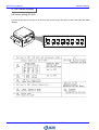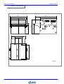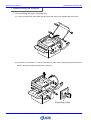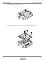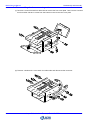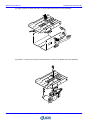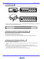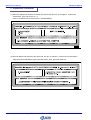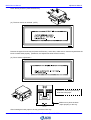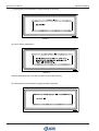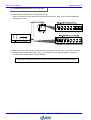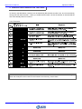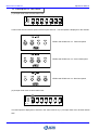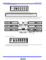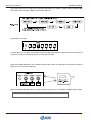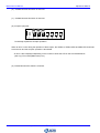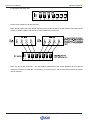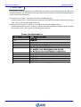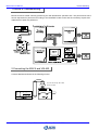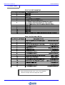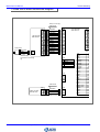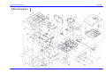
1
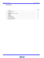
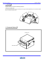
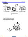
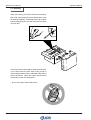
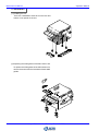
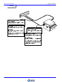
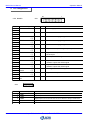
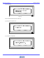
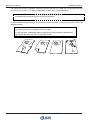
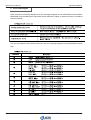
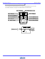
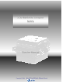
JCM Banknote Acceptor
MAYA
Service Manual
Copyright © 2004 JAPAN CASH MACHINE GERMANY GmbH
Operation Manual
Disassembly and Assembly Procedure
Adjustment Manual
Trouble Shooting
Parts List
Copyright © 2004 Japan Cash Machine Germany GmbH
JCM Banknote Acceptor
MAYA
Operation Manual
Copyright © 2004 Japan Cash Machine Germany GmbH
MAYA Service Manual
Operation Manual
Contents
1
2
3
4
5
6
7
8
9
10
11
Features ……………..………….………………………………………………………………..
Component Names ……………..……………………………………..…………………………
Precautions ……………..……………………………………..………………………………….
When the Acceptor is Jammed ……..…………………………………………………………..
Cleaning ………………..…………………………………………………………………………
Installation ……………….……………………………………………………………………….
Cabling …..………….…..………….…………………………………………………………….
Pin Assignment ……………..………..…………………………………………………………..
DIP Switch Setting ……………………………………………………………………………….
General Specifications …………………………………………………………………………..
Outside Dimensions ………………………...……………………………………………………
Japan Cash Machine Germany GmbH © 2004
Page
1
1
2
2
3
4
5
6
7
8
9
Contents
MAYA Service Manual
Operation Manual
1 Features
Validator MAYA provides the following features.
• Setting for accepting a bill
You can set the DIP switch to accept or refuse each of 5 types of bills independently. You can also set the DIP
switch to accept all 5 types of bills.
2 Component Names
Acceptor unit
Bill insertion slot
Japan Cash Machine Germany GmbH © 2004
1
MAYA Service Manual
Operation Manual
3 Precautions
1. Do not insert a torn, folded, or
wet bill. It will get jammed in the
unit.
2. Never expose the unit to water. The unit contains several precision electronic devices which
can be damaged if water or any
liquid is sprayed or spilled into the
unit.
3. Do not install the unit in a dusty
environment. Dust will lower the
performance of the bill sensor.
4 When the Acceptor is Jammed
(1) Loosen 4 knobs each from either side to open the
acceptor head and remove the jammed bills.
Japan Cash Machine Germany GmbH © 2004
2
MAYA Service Manual
Operation Manual
5 Cleaning
When the scanning unit and its sensor becomes dirty,
this could cause paper jams and deterioration of the
bill sensing capability. Periodically open the acceptor
and bill theft prevention unit and clean the inner parts
of these units.
Use a soft cloth or cotton swab to clean the inner parts.
If you cannot remove a stain, wipe it using a cloth or
cotton swab moistened with a standard head cleaner
sold in the market. Never use organic solvents such
as thinners to clean the inside parts.
• Do no use organic solvent like thinner.
Japan Cash Machine Germany GmbH © 2004
3
MAYA Service Manual
Operation Manual
6 Installation
(1) Installing the unit
There are 4 installation holes each on the rear and
bottom cover panels of the unit.
(2) Replacing the width guides of the bill insertion slot
To replace the width guides of the bill insertion slot,
remove the screws from the back side of these width
guides.
Japan Cash Machine Germany GmbH © 2004
4
MAYA Service Manual
Operation Manual
7 Cabling
Japan Cash Machine Germany GmbH © 2004
5
MAYA Service Manual
Operation Manual
8 Pin Assignment
1
26
2
CN 1
CPU BOARD
Pin No.
1
3
2
4
5
6
7
8
9
10
11
12
13
14
15
16
17
18
19
20
21
22
23
24
25
26
25
Name of Signal
Vcc
I/O
ACTIV
EXPLANATION
Power supply 12V
GND
Vss
VEND1
VEND2
VEND3
BUSY
ABN
INH
ACK
REJ
DATA
VALID
STKF
(+)
(–)
(+)
(–)
(+)
(–)
(+)
(–)
(+)
(–)
(+)
(–)
(+)
(–)
(+)
(–)
(+)
(–)
(+)
(–)
OUT
LO
Received currency type signal
OUT
LO
Received currency type signal
OUT
LO
Received currency type signal
OUT
HI
Signal to be output during acceptor operation
OUT
HI
IN
HI
Signal to be output when an error has occurred in
the acceptor
Bill reception inhibit signal
IN
LO
IN
LO
OUT
LO
Signal sent from external device to store bill after
validator outputs the VEND signal.
Signal sent from external device to return bill after
validator outputs the VEND signal.
Final signal of the VEND signal.
OUT
HI
Signal to be output when the stacker is full.
Not used.
NC
NC
CN 4
1
Pin No.
1
2
3
4
5
5
Name of Signal
LED1
LED2
LED3
LED4
GND
EXPLANATION
Signal output to turn on the LED when a bill can be received.
Signal output to turn on the LED when a bill can be received.
Signal output to turn on the LED when an error is detected or during a trouble status.
Signal output to turn on the LED when an error is detected or during a trouble status.
Japan Cash Machine Germany GmbH © 2004
6
MAYA Service Manual
Operation Manual
9 DIP Switch Setting
DIP switch setting (ID-0A2)
You can set the type of currency to be received, the escrow mode, and other functions using the DIP switch
settings.
Japan Cash Machine Germany GmbH © 2004
7
MAYA Service Manual
Operation Manual
10 General Specifications
1 Type of currency accepted
2 Direction of insertion
3 Receiving rate
5 Interface
See relevant specifications.
See relevant specification.
90% or more.Be sure to use the specified guide block for the bill insertion
slot. Includes the first time return and second timeacceptance. The following
bills, however, are exluded:
(1) Dirty, worn, wet, torn, and badly wrinkled bills.
(2) Bill with corner or edge folded and overlapped.
(3) Bills which have considerably different cutting dimensions and print
displacement.
Approx. 3 seconds
(Time interval until the storage confirmation signal is output after bills are
inserted and stacked.)
ID-0A2 : Photo coupler isolation input/output
7 Escrow
1 sheet escrow
8 Display
Four LEDs can be lit.
(1) LED ON signal output 2 lines during bill reception enabled status.
(2) LED ON signal output 2 lines during error detection and trouble status.
DC 12V(± 5%)
(1) Standby status
: 4VA
(2) Operation status
: 5VA (Max. 19VA)
(1) Operating temperature : 0 to 40 degrees Celsius
(2) Storage temperature
: -20 to 70 degrees Celsius
(3) Humidity
: 30% to 85%RH (without condensation)
(4) Light disturbance
: Do not expose the unit to direct sunlight.
(5) Installation
: Indoors
See the attached drawing.
Main unit 0.7 kg
Horizontal installation
4 Identification time
9 Power supply
10 Power consumption
11 Operating environment
12 Outside dimensions
13 Weight
14 Installation
Japan Cash Machine Germany GmbH © 2004
8
MAYA Service Manual
Operation Manual
11 Outside Dimensions
128
100
90
64
54
88.5
2
99
81
90
40
unit:mm
Japan Cash Machine Germany GmbH © 2004
9
JCM Banknote Acceptor
MAYA
Disassembly and Assembly
Procedure
Copyright © 2004 Japan Cash Machine Germany GmbH
MAYA Service Manual
Disassembly and Assembly
Contents
1 Disassembling the Acceptor
pege
1. Disassembling the upper scanning unit ......................................................................................... 1
2. Disassembling the lower scanning unit .......................................................................................... 3
Japan Cash Machine Germany GmbH © 2004
Contents
MAYA Service Manual
Disassembly and Assembly
1 Disassembling the Acceptor
1. Disassembling the upper scanning unit
(1) Loosen 2 screws each from either side to remove the upper cover together with the screws.
(2) Disconnect 2 connectors. Loosen 2 knobs each on both sides until the retaining bosses are released. Now lift the upper scanning unit to remove it.
Retaining boss
Japan Cash Machine Germany GmbH © 2004
1
MAYA Service Manual
Disassembly and Assembly
(3) Remove 1 screw from the left side panel.
(4) Remove 3 screws and disconnect the connector to detach the main CPU board.
Japan Cash Machine Germany GmbH © 2004
2
MAYA Service Manual
Disassembly and Assembly
2. Disassembling the lower scanning unit
(1) Remove 2 screws forward from either side to remove the front cover plate. Next, remove 2 screws
rear from either side and 1 screw from the bottom to remove the rear cover plate.
(2) Remove 2 knobs and 1 screw each from either side and disconnect the connector.
Japan Cash Machine Germany GmbH © 2004
3
MAYA Service Manual
Disassembly and Assembly
(3) Apply pressure to widen the frame on both sides and pull out the inner assembly.
(4) Remove 1 screw from the top and disconnect the connector to detach the motor assembly.
Japan Cash Machine Germany GmbH © 2004
4
MAYA Service Manual
Disassembly and Assembly
(5) Remove 2 screws and detach the LED board.
(6) Remove 1 screw to detach the motor.
Japan Cash Machine Germany GmbH © 2004
5
MAYA Service Manual
Disassembly and Assembly
(7) Remove the spring, 2 E-rings, and 2 gears to dismount the belt.
Japan Cash Machine Germany GmbH © 2004
6
JCM Banknote Acceptor
MAYA
Adjustment Manual
Copyright © 2004 Japan Cash Machine Germany GmbH
MAYA Service Manual
Adjustment Manual
Contents
Page
1 Connecting the MAYA to the Personal Computer
…………………………………………….
1
2 Setting the MAYA …………………………………………………………………………………
2
3 Running Environment of the Adjustment Software …………………………………………….
2
4 Starting up the PC-Adjustment Software
………………………………………………………
2
5 Adjustment Procedure …………………………………………………………………………….
3
6 Error Messages ……………………………………………………………………………………
10
7 Message-Position Conversion Diagram ………………………………………………………..
11
8 Connecting the MAYA and VM-450
…………………………………………………………….
13
9 Selection and Execution the Test Items …………………………………………………………
14
10 Description of Test Items …………..…………………………………………………………….
15
11 Error Code …………………………………………………………………………………………. 21
12 Sensor Layout …………..…………………………………………………………………………
Japan Cash Machine Germany GmbH 2004
23
Contents
MAYA Service Manual
Adjustment Manual
1 Connecting the EBA to the Personal Computer
1. Connect the EBA with the PC in the following manner.
Turn OFF the power and set both EBA-10/410 and VM-450 to the test mode.
IBM PC
MS-DOSV6.0
VM-450 Test Bench
EBA-02
Connect the cable
to serial port
I/F
Tool required for adjustment
Note: Automatic adjustment can be performed while the stacker box is installed in the unit. When the
guide block and mouthpiece are mounted on the insertion slot of the tray, remove them.
Japan Cash Machine Germany GmbH © 2004
1
MAYA Service Manual
Adjustment Manual
2 Setting the MAYA
(1) After confirming the VM-450 DIP switch settings and MAYA DIP switch settings, turn on VM-450.
VM-450 Test Bench
(2) The BSY LED of VM-450 will light and "_000_ _00" will appear on the segment display. At this time, the
LED next to the DIP switch of MAYA will light.
This status is called the test mode. After the test mode, communications to the PC is enabled.
3 Running Environment of the Adjustment Software
Type of personal computer to be used: IBM PC or AT compatible machines
RS-232C communication ports(D-sub 9 pins).
Communication port address: 3F8 to 3FF (serial port 1)
OS: MS-DOS V6.0 (The software cannot be operated by Windows and Windows DOS prompt.)
4 Starting up the PC Adjustment Software
(1) Turn on the PC and start up MS-DOS.
See the procedures in the relevant PC and MS-DOS manuals to turn on the PC and start up MSDOS.
(2) When MS-DOS is started, set the floppy disk containing the adjustment software in the PC.
(3) Change the current drive to the disk drive in which the adjustment software floppy disk is inserted.
For example, when the floppy disk is set in drive A:, type "A:".
(4) Start the adjustment software. Type "E02A-100" and press the Enter key.
Japan Cash Machine Germany GmbH © 2004
2
MAYA Service Manual
Adjustment Manual
5 Adjustment Procedure
(1) When the adjustment software is started, the initial screen (Screen 1) will appear. Confirm the
model name, type, and version (V*.**).
Press "1" and Enter key to select menu 1 (ADJUSTMENT).
Screen 1 (Initial Screen)
(2) Set both MAYA and VM-450 to the test mode, and turn on VM-450. Connect the communication
cable and confirm that MAYA is put in the test mode. Then, press the Enter key.
Screen 2
Japan Cash Machine Germany GmbH © 2004
3
MAYA Service Manual
Adjustment Manual
(3) The initialization of the EEPROM is being performed.
Screen 3
(4) The lever sensor is checked. (ON)
Screen 4
Open the MAYA tray and set the paper to check the lever sensors at the following 3 locations.
Japan Cash Machine Germany GmbH © 2004
4
MAYA Service Manual
Adjustment Manual
Close the tray and then press the Enter key.
(5) The lever sensor is checked. (OFF)
Screen 5
Remove the paper from the tray and press the Enter key. At this time, make sure to close the trayandclose the
knurls on both sides properly. (Otherwise, the adjustment value will be incorrect.)
(6) Photo sensor adjustment 1
Screen 6
There is no need to open the tray.
Insert the base paper.
Make sure to place the base
paper properly on the tray.
After inserting the base paper in the tray, press the Enter key.
Japan Cash Machine Germany GmbH © 2004
5
MAYA Service Manual
Adjustment Manual
(7) During photo sensor adjustment (approximately 15 seconds)
Screen 7
(8) Photo sensor adjustment 2
Screen 8
Place the base paper KS-35 on the tray and then press the Enter key.
(9) During photo sensor adjustment (approximately 5 seconds)
Screen 9
Japan Cash Machine Germany GmbH © 2004
6
MAYA Service Manual
Adjustment Manual
(10) Photo sensor adjustment 3
Screen 10
Remove the base paper and then press the Enter key.
(11) During photo sensor adjustment (approximately 10 seconds)
Screen 11
Japan Cash Machine Germany GmbH © 2004
7
MAYA Service Manual
Adjustment Manual
Feed speed check
Screen 14
Remove the MAG board and press the Enter key.
(12) During the feed speed check
Screen 15
(13) Completion of adjustment
Screen 16
Japan Cash Machine Germany GmbH © 2004
8
MAYA Service Manual
Adjustment Manual
The adjustment has been completed. Press the Enter key and then turn off VM-450. The program returns to
the initial screen (screen 1). To adjust another MAYA, select menu 1 (ADJUSTMENT).
MAYA is provided with a mode for confirming the bill receiving (identification) status. See the items
in the attached "Test Mode" document for more information.
Do not use bills like the ones below to confirm the bill receiving operation. If you insert such a bill, it will not be
identified properly.
(a)
(b)
(c)
(d)
Bills that are dirty, worn, wet, torn, and badly wrinkled.
Bills with folded and overlapped corners or edges.
Bills that have considerably different cutting dimensions and printing displacement.
Bills that are stained or have iron particles on them.
Japan Cash Machine Germany GmbH © 2004
9
MAYA Service Manual
Adjustment Manual
6 Error Messages
When a trouble occurs during adjustment, an error message will appear on the OPERATION comment field or
MESSAGE comment field and the adjustment will be interrupted. Repair or replace the parts in accordance
with the message.
You can also determine the trouble location from the error message displayed on the MESSAGE comment
field.
Japan Cash Machine Germany GmbH © 2004
10
MAYA Service Manual
Adjustment Manual
7 Messega-Position Conversion Diagram
You can determine the trouble location from the number of the MESSAGE error list. The "UP"
and "DOWN" indications in the figure are classified based on the bill feed route.
Japan Cash Machine Germany GmbH © 2004
11
MAYA Service Manual
Adjustment Manual
8 Connecting the MAYA to VM-450
(1) Connect MAYA and VM-450 in the following manner.
Set the DIP switches of both MAYA and VM-450 to the test mode. Be sure to turn off VM-450before
setting the test mode.
(2) Make sure that the DIP switches of both VM-450 and MAYA are set correctly. Then, turn on VM-450.
(3) The BSY LED of VM-450 lights and "_000_ _00" will appear on the segment display. At this time,
the LED next to the DIP switch of MAYA will light.
This status is called the test mode. In the test mode, various operation tests are enabled.
Japan Cash Machine Germany GmbH © 2004
12
MAYA Service Manual
Adjustment Manual
9 Selection and Execution the Test Items
As shown in the table below, a test item can be selected by DIP switches number 2 to 8, and it is executed by
turning OFF DIP switch number 1. When you set DIP switch number 1 to ON, the test item is canceled and the
test mode standby status is resumed.
List of Test Items
Note: Automatic adjustment can be performed while the stacker box is installed in the unit. When the guide
block and mouthpiece are mounted on the insertion slot of the tray, remove them.
Japan Cash Machine Germany GmbH © 2004
13
MAYA Service Manual
Adjustment Manual
10 Description of Test Items
(1) Acceptor feed motor forward rotation test
Confirms the forward rotation speed of the acceptor feed unit. The feed speed is displayed on the VM-450.
VEND1 and VEND2 turn on. Fast feed speed
VEND2 and VEND3 turn on. Correct feed speed
VEND3 and VEND4 turn on. Slow feed speed
(2) Acceptor feed motor reverse rotation test
The feed speed is displayed on VM-450 in the same manner as (1)."Acceptor feed motor forward rotation
test".
Japan Cash Machine Germany GmbH © 2004
14
MAYA Service Manual
Adjustment Manual
(3) Acceptor sensor ON/OFF test
Confirms the ON/OFF level of each bill sensor of the acceptor feed unit.
Note: You can perform this test only after performing the automatic adjustment.
When a bill is fed into the feed route of the acceptor, the VEND1 to VEND4, ABN, and STKF LEDs of VM-450
will light. (This test only confirms the operation of sensors which detect whether a bill is present or not.)
(4) Acceptor I/F test (OUT)
This test allows you to confirm the operation of the output signal line from the acceptor to the external device
(controller) according to the lighting sequence of the VM-450 LEDs.
Japan Cash Machine Germany GmbH © 2004
15
MAYA Service Manual
Adjustment Manual
The signals sent from the acceptor are sequentially indicated by the VEND1, VEND2, VEND3, VEND4, ABN,
and STKF LEDs of VM-450. (Make sure the BSY LED is lit.)
(5) Acceptor I/F test (IN)
This test allows you to confirm the operation of the input signal line from the external device (controller) to the
acceptor according to the lighting sequence of the VM-450 LEDs.
When the ENABLE/DISABLE, REJ, and ACK switches are turned on at VM-450, the acceptor will output a
signal to turn on the LEDs of VM-450.
When the ENABLE/DISABLE, REJ, and ACK switches are turned on, the VEND2 to VEND4 LEDs will light.
Before performing this test, perform 3-(4) "Acceptor I/F test (OUT)".
Japan Cash Machine Germany GmbH © 2004
16
MAYA Service Manual
Adjustment Manual
(6) Omitted because this switch is reserved.
(7) Omitted because this switch is reserved.
(8) Acceptor aging test
Periodically repeats the acceptor operation.
When an error occurs during the operation of the acceptor, the VEND1 to VEND3 LEDs and ABN LED of VM-450
are turned on and the acceptor operation is terminated.
An error code is displayed depending on the number of times the LED on the CPU board flashes.
(See 4-(1) Error Code (Malfunction) List.)
(9) Omitted because this switch is reserved.
Japan Cash Machine Germany GmbH © 2004
17
MAYA Service Manual
Adjustment Manual
(10)Acceptor bill reception test
Confirms the bill receiving operation of only the acceptor.
After the initial operation is completed, a bill can be received and the rate of receiving bills can be confirmed.
When the model (ROM) supporting the HI security is tested, bill receiving with the HI security function can be
confirmed if you turn on DIP switch No. 8 after the initial operation is completed.
Note: Even if DIP switch No. 1 is set to ON, the test mode will not be resumed when this test is executed.
VM-450 indicates that a bill has been received.
The type of currency is indicated by means of
the combination of lighted LEDs.
If a bill is not received successfully, check the following items.
(a) A bill is not accepted
Acceptor operation error. Check the number of times the LED on the CPU board flashes and repair or
replace the necessary parts. (See 4-(1) Error Code (Malfunction) List.)
(b) A bill is rejected
Acceptor identification unit error. Check the number of times the LED on the CPU board flashes and adjust
(clean the identification unit), repair, or replace the necessary parts. (See 4-(2) Error Code (Rejecting a
Bill) List.)
Note: Do not use bills like the ones below to confirm the bill receiving operation. If you insert such a bill, it
will not be identified properly.
(a)
(b)
(c)
(d)
Bills that are dirty, worn, wet, torn, and badly wrinkled.
Bills with folded and overlapped corners or edges.
Bills that have considerably different cutting dimensions and printing displacement.
Bills that are stained or have iron particles on them.
Japan Cash Machine Germany GmbH © 2004
18
MAYA Service Manual
Adjustment Manual
(11)Acceptor DIP switch test
Confirms the operation of all DIP switches.
When the DIP switch test starts, all DIP switches are turned ON. However, the DIP switches correspond to the
VEND1 to VEND4 LEDs of VM-450 when contact defects are confirmed.
When you turn on DIP switch No. 1, this test mode is ended and the DIP switch operation can no longer be
confirmed. However, if switch No. 1 is defective, you cannot enter or exit the test mode and thus the trouble
can be detected.
Japan Cash Machine Germany GmbH © 2004
19
MAYA Service Manual
Adjustment Manual
11 Error Code
If an operation cannot be performed successfully when you perform various operation tests, the LED on the
CPU board will flash. You can determine the error cause and error location by confirming the flashing and the
number of times the LED flashes.
(a) The bill is not accepted. (The LED on the CPU board flashes slowly.)
Acceptor operation error. Check the number of times the LED flashes and repair or replace the necessary
parts. (See 4-(1) Error Code (Malfunction) List.)
(b) After the bill is received, it is rejected. (The LED on the CPU board flashes rapidly.)
Acceptor identification unit error. Check the number of times the LED flashes and adjust, repair, or replace
the necessary parts. (See 4-(2) Error Code (Rejecting a Bill) List.)
Japan Cash Machine Germany GmbH © 2004
20
MAYA Service Manual
Adjustment Manual
*: When the Photo Sensor errors 1 to 5 occur frequently,
clean the acceptor head and adjust the sensor.
Japan Cash Machine Germany GmbH © 2004
21
MAYA Service Manual
Adjustment Manual
12 Sensor layout
Japan Cash Machine Germany GmbH © 2004
22
JCM Banknote Acceptor
MAYA
Trouble Shooting
Copyright © 2004 Japan Cash Machine Germany GmbH
MAYA Service Manual
Trouble Shooting
Contents
pege
Introduction .............................................................................................................................................. 1
1 Outline of Troubleshooting ....................................................................................................................... 2
2 Connecting the EBA and VM-450 ............................................................................................................ 2
3 Bill Identification Operation Test Procedure ............................................................................................ 3
4 EBA Trouble Indication and Bill Rejection Trouble Indication .................................................................. 4
5 Trouble Classification .............................................................................................................................. 5
6 Error Code ............................................................................................................................................... 9
7 Sensor layout ........................................................................................................................................ 10
8 Printed circuit board connection diagram ............................................................................................... 11
Japan Cash Machine Germany GmbH © 2004
Contents
MAYA Service Manual
Trouble Shooting
Introduction
• Many troubles of the validator are caused by minor reasons. Before replacing any part, be sure to
check whether connectors are connected properly and there is no line breakage in a cable harness.
• If the validator frequently rejects a bill, the magnetic head and conveyor belt may have a layer of iron
particles on them. Clean these areas.
• Observe the operating conditions of the validator carefully when you turn on the power. This is important for
the detection of a trouble cause and defective location.
• Whenever you disassemble and repair the validator head, be sure to adjust the sensors.
Perform repairs in accordance with Chapter 7, "Adjustment Manual
Performance Test", and Chapter 4, "Disassembly Procedure".
Japan Cash Machine Germany GmbH © 2004
1
MAYA Service Manual
Trouble Shooting
1 Outline of Troubleshooting
MAYA can find a trouble cause by performing the "bill identification operation test". The performance test or
sensor adjustment is performed according to the identified trouble cause and the necessary repairs and
replacement of parts are performed.
2 Connecting the MAYA and VM-450
Connect MAYA and VM-450 in the following manner.
Connect the 26-pin flat cable
to the acceptor.
Japan Cash Machine Germany GmbH © 2004
2
MAYA Service Manual
Trouble Shooting
3 Bill Identification Operation Test Procedure
3-1 To perform the bill identification operation test, first set the acceptor to the test mode standby status.
Set the DIP switches of MAYA and VM-450 as shown in the figure below. Make sure to turn off VM450 before changing the DIP switch.
3-2 When you turn on the power of VM-450, the BSY LED lights and "_000__00" will appear on the segment
display.
At this time, the DIP switch next to the LED ofMAYA will light.
This is called the test mode standby status. You can perform various operation tests in this status.
3-3 Executing the identification operation tests
Set the DIP switch of the acceptor as shown in the figure below.
MAYA DIP switch setting
3-4 When you turn off DIP switch No. 1 of the acceptor, the acceptor can receive a bill and you can confirm the
bill receiving rate after the initial operation is completed.
VM-450 indicates that the bill is received and the type of currency is indicated by means of the VEND1 to
VEND3 LED combinations.
VM-450 currency type signal indication
Japan Cash Machine Germany GmbH © 2004
3
MAYA Service Manual
Trouble Shooting
Do not use bills like the ones below to confirm the bill receiving operation. If you insert such a bill, it will not
be identified properly.
(a) Bills that are dirty, worn, wet, torn, and badly wrinkled.
(b) Bills with folded and overlapped corners or edges.
(c) Bills that have considerably different cutting dimensions and printing displacement.
(d) Bills that are stained or have iron particles on them.
4 MAYA Trouble Indication and Bill Rejection Trouble Indication
4-1 When the MAYA cannot store the bills successfully, the LED on the CPU board will flash as shown in the
figure below. You can determine the trouble by confirming the flashing condition and number of times the
LED flashes.
(a) The bill is not accepted
MAYA operation error. The LED on the CPU board flashes slowly. Check the number of times the LED
flashes and see 6 "Error Code (Malfunction) List".
(b) After the bill is received, it is rejected.
Acceptor identification unit error. The LED on the CPU board flashes rapidly. Check the number of times
the LED flashes and see 6 "Error Code (Rejecting a Bill) List".
Check how the
LED flashes.
Japan Cash Machine Germany GmbH © 2004
4
MAYA Service Manual
Trouble Shooting
5 Trouble Classification
The trouble causes are mainly divided into the following 6 types. Check the operating conditions.
Japan Cash Machine Germany GmbH © 2004
5
MAYA Service Manual
Trouble Shooting
(1) Test mode cannot be started.
(2) Indication LED does not turn on.
(3) Normal signal cannot be sent from acceptor to controller.
*1: See Chapter 7, "Adjustment Manual" for details about the sensor adjustment.
Japan Cash Machine Germany GmbH © 2004
6
MAYA Service Manual
Trouble Shooting
(4) Bill is rejected and rate of receiving bills is poor.
*1: See Chapter 7, "Adjustment Manual" for details about the sensor adjustment.
*2: Determine the defective position from 6 "Error Message" in the Adjustment Manual and replace the parts
as required.
(5) Bill is not fed smoothly. (Jammed in feed route.)
Japan Cash Machine Germany GmbH © 2004
7
MAYA Service Manual
Trouble Shooting
(6) Bill is not accepted. The LED next to the DIP switch flashes repeatedly.
(Stop state due to malfunction)
*1: See Chapter 7, "Adjustment Manual" for details about the sensor adjustment.
Japan Cash Machine Germany GmbH © 2004
8
MAYA Service Manual
Trouble Shooting
6 Error Code
*: When the Photo Sensor error 1 to 5 occur frequently,
clean the acceptor head and adjust the sensor.
Japan Cash Machine Germany GmbH © 2004
9
MAYA Service Manual
Trouble Shooting
7 Sensor layout
Japan Cash Machine Germany GmbH © 2004
10
MAYA Service Manual
Trouble Shooting
Printed circuit board connection diagram
Relay harness
990-05-02
LED board
990-06-02A
Feed motor
+ BROWN
1
RED
2
LIST
850-04-03
Feed moto harness
CN1
1
2
3
4
5
6
7
8
9
10
11
12
13
14
15
16
BROWN
RED
ORANGE
YELLOW
GREEN
BLUE
PURPLE
GRAY
WHITE
BLACK
BROWN
RED
OLENGE
YELLOW
GREEN
CN2
1
2
3
4
5
6
7
8
9
10
11
12
13
14
15
CN4
1 LED-1
2 LED-2
3 LED-3
4 LED-4
5 GND
CN5
1
2
3
4
990-05-02
MAG board
990-06-03A
CN1
1
2
3
BROWN
RED
OLENGE
CN6
1
2
3
C PUboard
990-06-01A
12V
GND
12V
GND
VEND1 +
VEND1 VEND2 +
VEND2 VEND3 +
VEND3 BUSY
BUSY
ABN +
ABN INH +
INH ACK +
ACK REJ +
REJ DATA VAL +
DATA VAL STKF +
STKF TXD
RXD
CN3
1
2
3
4
5
6
7
8
9
10
11
12
CN1
1
2
3
4
5
6
7
8
9
10
11
12
13
14
15
16
17
18
19
20
21
22
23
24
25
26
MAG harness
Japan Cash Machine Germany GmbH © 2004
11
JCM Banknote Acceptor
MAYA
Parts List
Copyright © 2004 Japan Cash Machine Germany GmbH
MAYA Service Manual
Parts List
Contents
Page
Parts Diagram……………………….……………………………………………………………….. 1
Parts List…………………..………………………………………..…………………………………. 2
Japan Cash Machine Germany GmbH 2004
Contents
MAYA Service Manual
Parts List
Parts Diagram
Japan Cash Machine Germany GmbH 2004
1
MAYA Service Manual
Parts List
>> Back to the Diagram >> Back to the Diagram >> Back to the Diagram >> Back to the Diagram >>
Parts List
No.
EDP-No.
1
2
3
4
5
6
7
8
9
10
11
12
13
14
15
16
17
18
19
20
21
22
23
24
25
26
27
28
29
30
31
32
33
34
35
049325
055524
042477
055410
049356
049357
042477
046073
042379
049331
049326
049327
049359
049360
003705
049330
049332
042383
042376
005229
042352
049329
042361
042477
040343
055411
055533
042477
042353
042394
042348
042347
042385
003707
064598
Parts Name
Cover
CPU Substrate Unit
M2.6x5 Bind Tapping Screw
U-Guide Type M
Side Plate R Assy.
Side Plate L Assy.
M2.6x5 Bind Tapping Screw
M2.6x4 Bind Screw (black)
Screw
Shutter shaft
Shutter R
Shutter L
Shutter Spring R
Shutter Spring L
Ø2 E-type Clip (SUS)
End Lever
Lever Pin
Spring-3
Pin-1
Head Roller Spring
Roller-2
Spring Bracket-3
Spring Bracket-1
M2.6x5 Bind Tapping Screw
Reflector Sensor Lens
D-Guide (Type M)
LED Substrate Unit
M2.6x5 Bind Tapping Screw
Sensor Cover
Motor Bracket Assy.
Pulley-1
Roller-1
Timing belt 103 MXL 4.8V
Ø3 E-type Clip (SUS)
Gear-1
(black)
(black)
(black)
(black)
Japan Cash Machine Germany GmbH 2004
3
MAYA Service Manual
Parts List
Back to the Diagram >> Back to the Diagram >> Back to the Diagram >>
Back to the Diagram
Parts List
No.
EDP-No.
36
37
38
39
40
41
42
43
44
45
46
47
48
49
50
51
52
53
54
55
56
57
58
59
60
61
62
63
64
65
66
67
68
003705
042392
042351
042345
005230
056305
003600
064597
014548
049322
049323
049324
046073
042477
055534
034864
066661
040342
056813
Parts Name
Ø2 E-type Clip (SUS)
Pulley Arm Assy.
Pulley-2
Gear-2
Spring-2
Motor Unit
M3x5 Screw
Encorder
M2.6x5 Flat Head Screw (black)
Frame
Front Cover
Rear Cover
M2.6x4 Bind Screw (black)
M2.6x5 Bind Tapping Screw (black)
Relay Harness
Cable Tie
MAG Dummy
Sensor Bush (Ø5)
Rom Cover
Japan Cash Machine Germany GmbH 2002
3