1
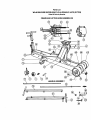
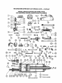
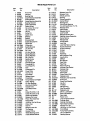
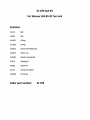
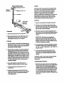
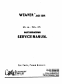
WEAVER
MODEL
eJACKCORP.
WA-85
PARTS BREAKDOWN
SERVICE MANUAL
F OR
PARTS,
PLEASE
CONTACT:
Tou-Fall: 888-214-8410
TIU,HOHI: 815-458-'216
Fax:815-458-9350
.,n
E-MAIU CAlTLIOAMRlTICH •
WWW.CAmll!qvmlINT.COM
Box 3; BRAIDWOOD, IL 60408
WIISITI:
P.O.
Parts List
WA-85 WEAVER SUPER·GIANT LO·Hi·DRAULlC
Order All Parts by Number
JACK (20 TON)
@
MISCELLANEOUS CASTINGS AND STEEL PARTS
CUP LEATHERS, PACKING, GASKETS AND FOLLOWERS
(o---6i9>
CASTER
ASSEMBLY
10
® @
oJ. ~
16
-----.@
@
@
A8-15994
\
\'
®
@
®
21
)~
~
IO@)
~
.~_®~®
@d
~
\
9
.
~
41
®~~
®~
\
Q_---
~.
~
-@)
~-®
®
a
o® d-@
©-@
~_~
~..d?-@
,® ®
~~~63~®
__
@))
----@@
89
@
909192
74
82
83
®
@@
!-@
§
~
6"1'4)
----
@
Includes 96 & 97
11
Cylinder shell
@
Cylinder complete
Item
No.
Part
No.
1. S6605
2. 5-2232
3. S·24650
4. A5-15814
5. M·2028
6. A5-15815
7. 5-15429
8. AS·15957
9. M-1152
10. S-4594
11. 5-1571
12. 5-9522
13. 5-293
14. 5-15971
15. 5-15398
16. M-2043
17. 5-15975
18. 5-15973
19. 5-15987
20. AS·15944
21. AS·15950
22. 5-15974
23. A5-15954
24. S·16051
25. 5-16059
26. 5-16058
27. S·15972
28. S·16098
29. 5-27384
30. 5-7394 .
31. S-6551
32. 5-6552
33. S-15978
34. 5-15976
35. A5-16051
36. 5-508
37. M·1416
38. M·1148
39. M·2045
40. AS·16039
41. S-1365
42. 5-15996
43. 5-5125
44. M·1414
45. AS-20495
46. 5-6549
47. 5-794
48. S-3234
49. S-5200
50. 5-16070
51. AS-16054
52. 5-16032
53. 5-23872
54. 5-16023
55. 5-15694
56.5-6586
57. M·1423
58. 5-5096
59. S·9147
60. 5-9149
Description
Acorn Nut
Jam Nut
Bearing Cap
Upper Bearing Assembly
Caster Bracket
Lower Bearing Assembly
Bearing Retainer
Caster Assembly
Caster Wheel
Hex screw 1/2 x 2·1/2
112Lockwasher
1/2 Nut
Cotter Pin
Caster Axle
Bearing
Saddle
Shoulder Bolt
Saddle Bracket Pin
Castle Nut
Lifting Arm
Saddle Bracket
Lift Arm Pin
Par. Link
Lift Arm Spring
Spring Retainer
Spring Retainer
Par. Link Pin
Saddle Screw
Spring Rod
Tlecasting Bolt
Tiecasting Pin
Foot Pedal Pin
Axle
Crosshead Pin
Cover Plate
Hex Nut 1/2
Foot Pedal
Release Lever
Crosshead
Pump Bracket or M-2237
Compo Spring
Lift Arm Bushing
Aluminum Washer
Handle Yoke
Yoke Return Rod
Pin
Cotter Pin 3/16 x 1-112
Cotter Pin 3/16 x 2-1/2
Inside Hub Washer
Release Pull Lever
Piston Rod Assembly
NamePlate
1/4-20 Sq. Hd. Set Screw
Piston Cup
Roll Pin
Release Lever Pin
Tie Casting
Grease Fitting
Wheel Bearing Cover
Inside Wheel Washer
Item
No.
61.
62.
63.
64.
65.
66.
67.
66.
69.
70.
71.
72.
73.
74.
75.
76.
77.
78.
79.
80.
81.
82.
83.
84.
85.
86.
87.
88.
89.
90.
91.
92.
93.
94.
95.
96.
97.
98.
99.
100.
101.
102.
103.
104.
105.
106.
107.
108.
109.
110.
111.
112.
113.
114.
115.
116.
117.
118.
119.
120.
Part
No.
S-4710
S-5123
5-1863
5-7412
AS-15930
AS-16037
M-1167
5-11103
5-1877
S·21050
S-5173
S-2591
S-1934
S-5176
AS-21052
S-9786
S-5261
AS-6660
AS-6550
5-2329
AS-6545
5-21051
S·15047
S·17829
5-1805
S-16196
S·20866
S·5122
S-5355
5-7026
S-5178
S-16022
S·22964
M-2041
M-2042
5-15969
5-24497
S-7075
AS-22107
S-24648
5-7413
S·1863
S-3282
S·5652
S-2
M-1157
S-3010
5-15968
M·2167
S-3
S-4
AS-15962
AS-15961
AS-15965
S-23689
S-5OO8
AS-12588
A5-24498
S·543
5-25661
Description
Release Lever Pin
Release Yoke
5/16-24 Jam Nut
Packing
Frame Assembly
Center Wheel
Packing Nut
Front Roller Bearing
1/4 x 3/4 Cap Screw, Hx. Hd.
Release Valve
Valve Guide
Release Spring
Lock Nut 3/8
Release Packing Nut
Packing House Assembly
Comp. Spring
Release Rod
Handle Shell
Lock Rod
Lock Rod Return Spring
Handle Assembly
O-Ring Housing
O-Ring
O-Ring
Pipe Plug
Ball Chamber Plug
Handle Grip
5/8 Ball
Ball Weight
Vent Plug
Pipe Plug
Piston Packing
Cylinder Cap Gasket
Cylln~erCap
Packing Nut
Piston Rod
Pump Piston Rod
Release Lock
Release Lever Assembly
Pump Cup
Pump Cup Washer
Hex Nut
7/16 Ball
318Pipe Plug
Line Connector
Release Lever
3/4 Int. Lockwasher
Ram Cup Washer
Ram Head
Return Line
Line Connector Elbow
Cylinder Shell
Cylinder Complete
Ram Head Assembly
Roll Pin 1/4 x 1/2
1/4-20 Sq. Hd. Set Screw
Front Wheel
Pump Rod Assembly
1/4 Lock Washer
Bearing Spacer
KJ-l09 Seal Kit
For Weaver WA-85 20 Ton Jack
Contains:
$-5122
Ball
$-3282
Ball
$-15047
DRing
$-17829
DRing
$-16022
Piston Rod Packing (3)
$-16023
Piston Cup
$-22964
Cylinder Cap Gasket
$-7412
Packing (3)
$-3083
Cotter Pin
$-5125
Aluminum Gasket
$-24648
Pump Cup
Order part number:
S8rv1ceInstructions
t!
Handle ~
Sot Screw
4i! !j
II
Handle Lock Lever
Release Lever lock
Lock Rod
Remove the filler plug and with the saddle DOWN
put In MIL·F·17111 011 until the level comes up to
within 1/4" to 3/8" below filler hole. Overfilling
causes 011 to spurt out the vent hole as jack Is
lowered, or mal prevent jack from lowering
properly. Insufficient 011 causes jack to lift only part
way. Always be sure to put In 011 only when the
saddle Is down. Be careful not to let any dirt get
into the reservoir while the Filler Plug Is out.
1. Keep all working parts thoroughly lubricated.
2. Packing nuts at the piston and Rump plunger
should be kept moderately tight. These packlngs
are NOT under high pressure, and should only be
tight enough to prevent leakage.
1. Check the handle set screw for tightness.
2. Remove and discard the vent filler plug. This Is
very Important, as the vent hole must always
be kept open so the jack can "breathe."
To Operate
1. The Jack Is easily maneuvered by depressing the
Handle Lock Lever until the lock rod engages
one of the two handle positions, and then pivot·
ing the jack on Its rear casters.
2. Place the Jack In position so that the saddle will
engage an approved lifting area of the vehicle.
The saddle Is raised to the contact point by the
foot pedal. Light loads may be raised by the foot
pedal alone. On low clearance vehicles It Is often
advantageous to operate the foot pedal by hand
while watching to assure proper saddle contact.
Surface on which jack rests should be fairly flat
to prevent twisting of frame. Load should be
centered In saddle.
3. Pump with handle for easy lifting. Do not
attempt to raise jack beyond Its travel stops.
4. To lower the load, pull back gently on the
release lever.
5. Be certain that area beneath vehicle Is clear
before lowering vehicle. Always use the release
lever lock to prevent unintentional operation
of the release lever.
3. Ball valve may be removed for Inspection and
cleaning by removing the Ball Chamber Plug and
turning the Jack on Its side, allowing the ball to
roll out.
IMPORTANT: Whenever It Is necessary to
loosen or remove the Ball Chamber Plug, the
gasket should be replaced with a new one. 011
leakage at this point is usually caused by trying
to use an old gasket over again.
4. If pumping falls to raise the rated load, the lower
ball valve Is leaking, and It should be Inspected
for dirt or other obstruction. Also check for
proper oil level.
5. If the load raises on the down stroke of the
handle and Immediately settles back, forcing
the handle up, It shows the upper ball valVe Is
leaking.
WARNING: Always use stands to support vehIcle
before attempting under vehicle repairs or
Inspections.
1. Should the 011 supply run too low, the jack may
become alr·bound and work on only a half stroke
of the handle. Fill the jack with oil, raise the
saddle, and then lower the saddle while holding
the foot pedal depressed. This will flush out any
air In the system, and excess 011 may run out ot
the vent. Be sure jack Is properly filled with 011
before putting It back In service. 011 should cover
piston rod.
To Remove CyUnder
1. Remove the cotter In the cross head.
2. Remove the cotter and pin In the pump.
3. Remove the cotter and pin In the release yoke.
4. Place cotter key In while depressing foot pedal.
This allows for easy removal and reassembly
If spring Is left on return rod.
5. Raise the lifting arm by means of the saddle,
and place a block of wood between the arm and
frame to hold up the arm.
6. This releases the cylinder at the forward end,
so that It may be removed as a complete unit,
for service.
To Replace Cup
1. After removing the cylinder unit 8S described
above, place It In a vise. Note that the vise Jaws
should grip the steel block, not the steel cylinder.
Set the unit In the vise with tne steel cylinder
and piston up. Remove the vent plug.
2. Unscrew the cylinder cap and 11ftthe piston out
of the cylinder.
3. Remove the nut and washer which holds the cup
at the end of the piston; put In the new cup, and
replace nut and washer.
4. In fitting the new cup Into the cylinder, USE
GREATCARE as the cup passes the filler plug
hole not to cut or otherwise damage the cup.
Then replace the cylinder cap.
5. To replace the small cup on the pump, tum the
cylinder unit pump end upward In the vise.
6. Unscrew the packing nut and pull out the pump
plunger. Remove the nut that holds cup to end of
plunger, Insert new cup, and replace nut.
1. A means to manually release Jack and safety
overload circuit. If underloaded Jack bleeds
down, release valve may be out of alignment.
2. In release group assembly,
spring governs load jack will 11ft.When pressure
of cylinder overcomes spring tension the release
valve floats off seat. It Is Imperative that the
release valve floats freely In release group
assembly. To check: use forefinger and thumb
to grasp the release valve when the release
clevis pin passes thru, and wiggle from side to
side. There should be a minimum of .002 to .004
clearance. If no movement Is noted, remove hex
nut, release valve guide and release spring,
and place release valve with release valve guide
back In release nut. Tap end of release spring
with Brass hammer. Slide release valve guide
Into position and noting where alignment Is off,
correct misalignment by tapping welded needle
bracket accordingly with Brass hammer. Re·
assemble and set pressure by hydraulic means.
Note: This procedure should only be done by a
qualified Authorized Service Depot.