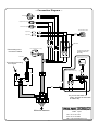
1
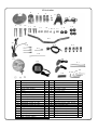
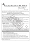
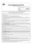
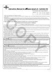
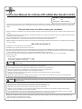
Instruction Manual for 4-Stroke DIO (AF62) Bar Handle Full Kit
CO
Item No.
:06―02―0301
Fits
:Dio
Frame Nos :AF62-1000001 ∼
・Thank you for purchasing one of our TAKEGAWA-made products. Please strictly follow the following instructions in installing and using the kit.
・Before installing the kit, please be sure to check the kit contents. Should you have any questions about the kit, please contact your local motorcycle dealer.
Read all instructions first before starting the installation.
◎ We do not take any responsibility for any accident or damage whatsoever arising from the use of the kit not in conformity with the instructions in the
manual.
◎ We shall be held free from any responsibility or compensation whatsoever for any glitch in the parts other than ours if the glitch takes place after the
installation and use of the products.
◎ If you make modifications to any product of the kit, we shall be held free from any guarantee of the product.
◎ You are requested not to contact us about the combination of our products with other manufacturers'.
◎Please note that this kit is designed for exclusive use in the above-mentioned fitting models and frame numbers only and that it cannot be mounted on
any other models.
PY
About the bar handle kit
◎ Installation of this kit requires some wire processing.
◎ Installation of turn signals requires boring of a front cover.
◎ In order to build a bar handle using this kit, please separately purchase the following TAKEGAWA-made parts and HONDA-made genuine parts.
◎As a stock meter assembly is to be removed, a fuel meter becomes unavailable. If you need the meter, please purchase an extra-cost TAKEGAWA made Fuel Meter Kit of Item No.09-01-2010, or Compat LCD Fuel Meter Kit of Item No. 07-04-0019.
◎ In case you use other steering handle and headlight than those included in this kit, please use them on your own responsibility.
Honda’s genuine parts:
For use in Today
Switch set, turn signal (part #: 35020-GFC-890) 1 piece
Socket COMP., headlight (33130-GFC-890)
1 piece
The following show the envisioned possibility of injuries to human bodies and property damage as a result of disregarding the
CAUTION following cautions.
・Always try to drive your motorcycle at a legal speed, abiding by the laws.
・Work only when the engine and muffler are cool. (Otherwise, you will get burned.)
・Do the installation with right tools. (Otherwise, breakage of parts or injuries to you may take place.)
・Always use a torque wrench to screw bolts and nuts tight and securely to the specified torque.
(Otherwise, these parts may get damaged or fall off, resulting in accidents.)
・As some products and frames have sharp edges or protruding portions, please work with your hands protected.
(Otherwise, you will suffer injuries.)
・Before riding, always check every hardware like screws for slack. If you find slack one, screw them securely up to the specified torque. (Otherwise, improper tightening may cause parts to come off.)
WARNING
The following show the envisioned possibility of human death or serious injuries to human bodies as a result of disregarding the
following warnings.
・When you notice something abnormal with your motorcycle while riding, immediately stop riding and park your motorcyle in a safe place to check what has gone wrong. (Otherwise, the abnormality could lead to accidents.)
・Before doing work, make sure your motorcycle is secure on level ground for safety's sake.
(Otherwise, your motorcycle could overturn and injure you while you are working.)
・Check or carry out maintenance of your motorcycle correctly according to the procedures in the instruction manual or service manual.
(Improper checking or maintenance could lead to accidents.)
・If you find damaged parts when checking and performing maintenance of your motorcycle, do not use these parts any longer, and replace
them with new ones. The continued use of these damaged parts as they are could lead to accidents.)
◎ Please be informed that, mainly because of improvement in performance, design changes, and cost increase, the product specifications and
prices are subject to change without prior notice.
◎ This manual should be retained for future reference.
-1-
Jan./09/’
07
Kit includes:
2
1
3
4
5
6
7
CO
8
9
10
11
19
12
13
14 15 16 17
18
20
21
25
22
23
24
27
28
26
PY
29
30
No.
1
2
3
4
5
6
7
8
9
10
11
12
13
14
15
16
17
18
Part Name
Handle post 1
Handle post 2
Handle upper holders
Handle lower holders
Collars
Headlight stay
Speedometer stay
Socket cap screws, 6 x
Socket cap screws, 6 x
Socket cap screw, 10 x
Buttonhead screws, 6 x
Buttonhead screws, 8 x
Flange U-nuts, 6 mm
Playn washers, 6 mm
Hex nut, 6 mm
Handle post pin
Meter-mount collars
Meter cushion rubbers
50
60
35
25
25
Qty
1
1
2
2
2
1
1
2
2
1
2
2
2
2
1
1
2
2
-2-
No.
19
20
21
22
23
24
25
26
27
28
29
30
31
32
33
34
35
31
33
35 34
Part Name
Plain washers, black
Handle
Sub-harness
Sub-cords, green
Sub-cord, black
Fuel meter cord
Starter switch
Electro taps
Headlight COMP.
Meter assembly
turn-signal lenses (clear lenses)
Heat shrinkable tube
Tie Wraps, 100 mm
L-shaped wrench, 3 mm
L-shaped wrench, 4 mm
L-shaped wrench, 5 mm
L-shaped wrench, 8 mm
32
Qty
4
1
1
3
1
1
1
5
1
1
2
1
2
1
1
1
1
Jan./09/’
07
∼ Installation Instructions ∼
1.Check the kit contents.
2.Prepare suitable tools for the work.
3.Make sure your bike is secure on a center stand.
4.Referring to the relevant HONDA’s service manual, remove the
following parts:
CO
・Front cover
・Handle front cover
・Handle rear cover
・Steering handle
5.
Detach a throttle housing, handle bracket L, handle grip L, etc. from the removed steering handle.
6.Remove the following parts from a standard handle bracket L, and install them onto the prepared turn-signal switch.
The numbers below show the order of removal, and install these parts in the reverse order of the removal.
① E-clip
② Parking lever pivot pin
③Parking lever COMP.
④ Lever return spring
⑤ Hex nut
⑥ Washer
⑦ Spring
⑧ Handle lever pivot screw
⑨ Rear brake lever
⑩ Rear brake cable
⑪ Stop switch
※ When installing, apply grease to pivots.
7.Fix a handle post pin to a
provided handle post 2.
At this point, fix the pin so the
tip of the pin sticks out
somewhat into the inside.
9.Install the handle post 1 with an
8x25 buttonhead screw, and tighten the screw to the
specified torque.
Torque: 22 N・m (2.2 kgf・m)
10.Loosely install a provided handle pipe for now. And decide the angle at which to install the steering handle, and where to fix a throttle housing and turn-signal switch.
On the clamps of a throttle housing and turn-signal switch, there is
a protrusion to position them. In installing them, either shave off the
protrusion or make a hole in the steering-handle pipe.
※ Carefully decide on where to install.
11.
Please place a steering handle pipe in the handle holder, and then fit
it to the handle post. At this point, put a provided collar into the
spot-facing on the handle-upper-holder front side. Install a
speedometer stay at the same time (See the fig. below). Adjust the
steering handle angle, and tighten the socket cap screw to the specified torque.
Torque: 12 N・m (1.2 kgf・m)
※Tighten the steering-handle holder so the space at the front and back is equal.
PY
Plain washer, 6 mm
Socket cap screw, 6 x 60
Speedometer stay
Socket cap screw, 6 x 50
Front
Collar
12.Install the throttle housing, handle grip L and others
removed from the standard
handle pipe.
8.Meshing the pin and grooves
on the stem shaft, install the handle post 2.
After screwing in the pin lightly,
lock the pin with a 6mm hex nut.
Put in a 10x35 socket cap screw
and tighten it to the specified torque.
Torque: 35 N・m (3.5 kgf・m)
Run the throttle cable, brake
hose and brake cable in front
of the handle post.
13.Install the headlight stay with
a 6x25 buttonhead screw and 6mm flange U-nut, and
tighten it to the specified torque.
Torque: 12 N・m
(1.2 kgf・m)
-3-
Jan./09/’
07
14.
Fix a provided speedometer to the stay. The speedometer is to be fixed using a rubber mount system. So, do the installation work referring to the figure below.
Install the starter switch onto the
steering-handle pipe, and run the
harness into the inside of the front
cover of a bike just like other cables.
Meter stay
Washer
Meter
CO
∼ Starter switch ∼
∼ Stop switch ∼
1.Onto the turn-signal switch, install the removed normal front stop switch assembly removed from the stock.
Meter cushion rubber
Nut (included in the meter)
Stop switch assembly
Meter-mounting collar
PY
2.
Connect the black, green and yellow terminals of the turn-signal switch
to the terminals of the same color of the stop switch.
15.Fix a headlight to the headlight stay. Position the headlight and
fasten it with a bolt and nut, which please tighten to the specified torque.
Torque: 25 ∼ 30 N・m (2.5 ∼ 3.0 kgf・m)
∼ Headlight ∼
This kit is designed on the premise that our TAKEGAWA-made Bates-type
headlight is to be used.
16.This kit is designed on the premise that the provided headlight is to
be used. Attach the headlight to the provided headlight stay.
Set the position of the headlight, and fasten it with a bolt and nut.
Torque: 25 ∼ 30 N・m (2.5 ∼ 3.0 kgf・m)
17.This kit is designed on the premise that the provided aero winker is
to be attached to the normal front cover. So, the work is needed to
pass the wires through the front cover.
First, make sure where to install the turn signals and where to pass
the wires, and either file down a part of the front cover or make a φ
5 or so hole in the cover. (The photo below shows an installation example.)
1.Remove sockets attached to
the Bates-type headlight, and
replace them with a prepared
socket COMP.
2.Connect the blue, white and green cord terminals of the turn signal switch to the cord terminals of the same color of the socket COMP.
∼ Turn signal ∼
This kit is designed on the premise that our TAKEGAWA-made aero turn signals
are to be used.
Connect the terminals of the right and left turn signals as follows:
Right turn signal: sky blue
Left turn-signal: orange
Earth cable: green
※ The aero winker is nonpolar.
Installation of Harness
∼ Sub-harness ∼
1.Put the terminal area of the harness from the turn-signal switch
into the headlight case.
2.Then route the remaining part of the harness into the inside of the front cover just like other cables.
3.With a provided sub-harness, connect two 9-pin couplers of the main
harness on the vehicle and a 9-pin coupler of the turn-signal switch.
NOTE: Be careful not to make wrong connection of couplers.
-4-
Jan./09/’
07
∼ About wiring of speedometer ∼
How to connect the electro tap
This kit is designed on the premise that our TAKEGAWA-made speedometer is
used.
For the power source, connect the meter to a cord from the turn-signal switch.
Connect the + power-source wire to the black, and the earth wire to the green,
respectively.
For the connection, please use an electro tap, or prepare a terminal separately by
yourself.
In case the connection is made with a terminal, branch wires with a provided
sub-harness. (See the fig. below)
CO
②
①
Stopper
③
Joining terminal
Vehicle wire
gray harness
cord
Black cord for LED
turn-indicator lamp
Connection
completed
Sub-cord (gr)
or
sb
Turn signals
gr
Meter (grounding wire)
Sub-cord (bk)
Turn-signal switch
gr / yl
① Before connecting the ②Fold back the tap at the cords, place them in the
arrow mark (⇒) to
relative conduits on the temporarily fix the cords.
electro tap. Particularly, set
③Then, fold back the the position of the LED cords securely until they
or the like until it is completely locked.
section with a joining
terminal. Securely hold it down with a plier
fully touch the stopper.
Stop switch
bk
Meter (+power source)
∼ Fuel meter ∼
PY
This kit is designed on the premise that our TAKEGAWA-made fuel meter kit is
used.
1.Remove a rear cover of a fuel meter assembly, and process the wires
as per the figure below. (Connect a provided fuel meter cord (green)
using an electro tap.)
※ Be sure to insulate the cut-off portions
Fuel meter
Fuel-meter lighting bulb
bl bk
Connect with an electro tap
Cut here
gr br bl bk
Fuel meter cord
gr
4-pin (rd)
Color abbreviation:
Black (bk) ,
Blue (bl)
Brown (br) ,
Green (gr)
Orange (or) , Red (rd)
Sky blue (sb) , White (wt)
Yellow (yl)
※If you are using a compact LCD fuel meter, please refr to its instruciton
manual.
2.After the processing, attach the cover again.
3.
Connect the 4-pin coupler (red) of the fuel meter and the terminal of the fuel meter cord to the 4-pin coupler (red) of the sub-harness and
to the terminal, respectively.
After installation of all hardware, start the engine in a well-ventilated place
to check that all hardware operate normally.
In case you detect some malfunction, please check for the bulb blowout or
poor cord-connection which can be the main cause.
-5-
Jan./09/’
07
∼ Connection Diagram ∼
wt
bl
gr
Headlight
CO
Right-side turn signal
Left-side turn signal
Stop switch
Stop switch
Fuel meter
※You will not be using
this coupler.
bk/wt
gr/yl
bk
Turn signal switch for Today
※Processing to the
fuel meter needed.
Provided starter switch
gr/yl
bk
bk/yl
sub-cord
gr
or
sb
PY
gr bl wt
bk
gr/yl
In the case of using the
starter switch set for Today
bk
gr/rd
gr
bl/wt
yl/wt
In case you are using
a starter switch set
for Today
Starter switch for Today
gr/yl
yl/gr
bk/yl
gr
bk
gr/yl
bk/yl
※If you use the swtich for
Today, process the wires with
an electro tap.
Main wire harness
-6-
3-5-16 Nishikiorihigashi Tondabayashi
Osaka Japan
TEL : 81-721-25-1357
FAX : 81-721-24-5059
URL : http://www.takegawa.co.jp
Jan./09/’
07