1
CiMAX 75xxA/76xx Scanner Technical
Reference Manual
Rev F, February 2002
EM-63165-1F
CiMAX 75xxA/76xx Scanner
Technical Reference Manual
Rev F, February 2002
Copyright © 2002 SICK Auto Ident, Inc.
This manual and the software described in it are copyrighted, with all
rights reserved. Under the copyright laws, no part of this publication may
be reproduced, stored in a retrieval system, or transmitted, in any form by
any means, electronic, mechanical, by photocopying, recording, or
otherwise, without prior written permission of SICK Auto Ident, Inc.
Information furnished by SICK Auto Ident, Inc. is believed to be accurate
and reliable and is subject to change without notice. However, no
responsibility is assumed by SICK Auto Ident, Inc. for its use or any
errors that may appear in this document, nor for any infringements of
patents or other rights of third parties, which may result from its use.
Factory Authorized Training
SICK Auto Ident, Inc. provides comprehensive product training. Contact
the SICK Auto Ident, Inc. Training Coordinator at 1-888-264-4641 for inhouse and on-site class schedules and rates.
CiMAX 7500A/7600/7650/7655
Technical Manual
SICK Auto Ident, Inc.
5 Shawmut Road
Canton, MA 02021 USA
(781) 302-2500
Fax (781) 828-3150
Getting Assistance
If you have questions or comments, please contact SICK Auto Ident, Inc.
at 1-888-264-4641. For additional assistance, contact:
•
Order Processing (Option #1)
•
Technical Support (Option #2)
•
Field Service Contracts (Option #3)
•
Customer Service Fax (781) 828-3150
Product names mentioned herein are for identification purposes only and
may be trademarks and/or registered trademarks of their respective
companies: OMNI, CiComm, CiFrame, CiMenu, CiMAX, CiPRO,
CiBOS, Scanstar, Starnode, and TALL Other references to trademarks are
the rights of their respective owners.
Printed in the United States of America.
Warning!
Warning!
WARNING! THIS EQUIPMENT GENERATES, USES, AND CAN RADIATE RADIO
FREQUENCY ENERGY AND, IF NOT INSTALLED AND USED IN ACCORDANCE
WITH THIS USER MANUAL, MAY CAUSE INTERFERENCE TO RADIO
COMMUNICATIONS. IT HAS BEEN TESTED AND FOUND TO COMPLY WITH THE
LIMITS FOR CLASS A COMPUTING DEVICES PURSUANT TO SUBPART J OF PART
15 OF FCC RULES, WHICH ARE DESIGNED TO PROVIDE REASONABLE
PROTECTION AGAINST SUCH INTERFERENCE WHEN OPERATED IN A
COMMERCIAL ENVIRONMENT. OPERATION OF THIS EQUIPMENT IN A
RESIDENTIAL AREA IS LIKELY TO CAUSE INTERFERENCE, IN WHICH CASE THE
USER, AT HIS OWN EXPENSE, MUST TAKE NECESSARY MEASURES TO CORRECT
THE INTERFERENCE.
THIS PRODUCT DOES NOT EXCEED THE CLASS A LIMITS FOR RADIO NOISE
EMISSIONS FROM DIGITAL APPARATUS SET FORTH IN THE RADIO
INTERFERENCE REGULATIONS OF THE CANADIAN DEPARTMENT OF
COMMUNICATIONS. (LE PRÉSENT APPAREIL NUMÉRIQUE N'ÉMET PAS DE
BRUITS RADIOÉLECTRIQUES DÉPASSANT LES LIMITES APPLICABLES AUX
APPAREILS NUMÉRIQUES DE LA CLASS A PRESCRITES DANS LE RÈGLEMENT
SUR LE BROUILLAGE RADIOÉLECTRIQUE ÉDICTÉ PAR LE MINISTÈRE DES
COMMUNICATIONS DU CANADA.)
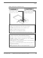
Caution - Use of controls or adjustments or performance of procedures other than those
specified in this manual may result in hazardous exposure.
Attention - l’utilisation de procédures de contrôle, de reglage ou d’utilisation autres que celles
specifiées dans ce manuel peut entrainer une exposition dangereuse à la lumière du laser.
Peligro - El uso de controles, ajustes o funcionamiento diferentes a los especificados en este
manual pueden resultar en exposición a el rayo laser.
Waarschuwing - Afwijkend gedrag op de in net handboek beschreven procedure kan schok en/of bestralingsgevaar teweegbrengen.
Rev F, February 2002
CiMAX 75xxA/76xx Scanner Technical Reference Manual
iii
Warning
Warning!
Vorsicht: Veränderungen der Justierungen oder Einstellungen, sowie sonstige
Veränderungen die nicht in diesem Manual beschrieben sind, können zu gefährlichen
Ausstrahlungen führen.
Varoitus - Kaikki muut huolto ja säätötoimenpiteet, joita ei ole tässa ohjeessa määritelty tai
maimittu, voivat aiheuttaa vaaratilanteen.
Attenzione - L’uso di controlli o tarature o l’asecuzione di procedure diverse da quelle
specificate in questo manuale possono causare pericolose esposizioni.
No operator serviceable part/controls in scanner. Refer service to factory authorized dealer.
Ne pas ouvrir - toute réparation effectuée par une personne non qualifiée peut entrainer la violation
des règles de securité relatives au laser.
Partes y/o controles del scanner que no se pueden manipular por el usuario. Contactar a el
distribuidor autorizado. Reparable sólo en fábrica.
Gelieve neit te openen - eigen veiligheid kan hierdoor in gevaar gebracht worden.
Versuchen Sie nich selbst irgendwelche Reparaturen oder Einstellungen im Innern des Gerätes
vorzunehmen. Da es innen kane vom Benutzer zu bedienenden Teile gibt, gefährdet an öffnen des
Gehäuses nur Ihre Sicherheit. Raparaturen nur durch eine autorisierte Fachwerkstatt.
Lukijan saa avata ja huoltaa vain maahantuojan valtuuttama korjaaja.
L’utente finale non può effettuare interventi di riparazione sugli scanner. Rivolgersi
esclusivamente al rivenditori autorizzati. I servizi di riparazione del produttore sono in USA.
Caution - Danger of explosion if lithium battery is incorrectly replaced. Replace only with
the same or equivalent type recommended by the manufacturer. Dispose of the used batteries
according to the manufacturer’s instructions.
Attention danger d’explosion si pile lithium mal branchée - remplacer par pièce d’origine
contrôlée - suivre les instructions du fabricant pour le recyclage des piles lithium usagées.
Peligro - Peligro de explosión si la batería de litio no se coloca correctamente. Reemplazaría
únicamente con el mismo tipo o equivalente recomendado por el fabricante. Utilizar las
baterías según las instrucciones del fabricante.
Waarschuwing - Ontploffingsgevarr bij foutieve vervanging batterij. Omwisseling
uitsluitend door analoog en door de fabrikant goedgekeurd type. Teruggave batterijen
volgens instructies de fabrikant.
iv
CiMAX 75xxA/76xx Scanner Technical Reference Manual
Rev F, February 2002
Warning
Vorsicht- Explosionsgefahr bei fehlerhaftem Austausch der Lithiumbatterie. Eventuellen
Austausch nur mit gleichem oder kompatiblen, vom Hersteller empfohlenen Typ.
Gebrauchte Batterien nur bei entsprechenden Sammelstellen entsorgen.
Varoitus - Räjähdysvaara jos litiumparisto asennataan väärin. Vaihda vain valmistajan
suosittelemaan samaan tai vastaavaan paristotyyppiin. Hävitä paristo valmistajan ohjeiden
mukaisesti.
Attenzione - Può esservi pericolo di esplosioni se le batterie al litio vengono sostituite in modo
non corretto. Tali batterie devono essere sostituite unicamente con lo stesso tipo di batterie
raccomandato dal produttore oppure con batterie di tipo equivalente. Le batterie usate
devono essere smaltite seguendo le modalità raccomandate dal produttore.
Rev F, February 2002
CiMAX 75xxA/76xx Scanner Technical Reference Manual
v
Warning
vi
Warning!
CiMAX 75xxA/76xx Scanner Technical Reference Manual
Rev F, February 2002
Contents
CHAPTER 1
Overview & Maintenance
1–1
Overview 1–1
Typical Physical Setup 1-1
CiMAX 7500A/7600 Laser Scanner 1-2
CiMAX 7550A/7650 Laser Scanner 1-2
CiMAX 7555A/7655 Laser Scanner 1-3
Keysheet 1-3
Software Updates 1-3
Specifications 1–4
Scanner 1-4
Configuration 1–4
Physical 1–4
Method of Illumination 1–5
Scan Rates 1–5
Power 1–5
Construction 1–5
Environmental 1–5
LED Status Indicators 1–5
Communications 1–6
Inputs 1–6
Outputs 1–6
Basic Interface Unit 1-6
Physical 1–6
AC Power 1–7
Inputs 1–7
Outputs 1–7
Standard Interface Unit 1-7
Physical 1–7
AC Power 1–7
Inputs 1–7
Outputs 1–7
Optional Solid-State Input/Output Modules 1–7
Electro-Mechanical Output Relay 1–8
Hex Interface Unit 1-8
Physical 1–8
AC Power 1–8
Inputs 1–8
Outputs 1–8
Optional Solid-State Input/Output Modules 1–8
Electro-Mechanical Output Relay 1–9
Maintenance
Rev F, February 2002
1–9
CiMAX 75xxA/76xx Scanner Technical Reference Manual
vii
Contents
CHAPTER 2
Installation & Setup
2–1
Unpacking & Inspection 2–1
Installation Checklist 2–1
Site Preparation 2-2
Physical Installation 2-2
Electrical Connections 2-3
On Site Testing 2-3
Operation Instruction 2-4
Final Approval 2-4
Site Preparation 2–4
Power 2-4
Setup 2-5
Photoeyes & Tachometer Installation 2-5
Installing the Tachometer 2–5
Mounting Presence Photoeyes 2–6
Mounting Photoeye Tree Bracket 2–6
Scanner Installation 2-7
Connecting CiMAX Scanner & Basic/Standard/Hex Interface Unit 2-7
On-Off Switch 2–7
CHAPTER 3
Controls, Connectors, & Indicators
Scanner
3–1
3–1
LED Display 3-1
Setup 3–2
Presence 3–2
Decode 3–2
Xmit/Rcv 3–2
I/O 3–2
Pwr/Laser On (green) 3–2
Interface Units
3–2
Basic Interface Unit 3-2
I/O Panel Inputs & Outputs 3–4
Scanner Connection 3-4
Connection to a Host 3-5
Standard Interface Unit 3-5
Hex Interface Unit 3-5
Standard Interface Connections 3-6
AC Power 3-6
Hex Interface Connections 3-7
Control Input Connections 3-8
Interface Unit Inputs 3–8
Programmable Interface Controller Inputs 3–9
Optional Input Relay Modules 3–9
Control Output Connections 3-9
Special Inputs & Outputs 3-9
Laser Control 3–9
Beeper 3–10
Communications Inputs & Outputs 3–10
DC Power Outputs 3–10
Solid State Input & Output Circuits 3–10
viii
CiMAX 75xxA/76xx Scanner Technical Reference Manual
Rev F, February 2002
Contents
Standard Interface Unit Circuit Board 3-12
Hex Interface Unit Circuit Board 3-13
Programmable Interface Controller Board 3-14
Relays in the Interface Units 3-14
Standard Interface Unit 3–14
Hex Interface Unit 3–15
Typical Relay Wiring Examples 3-15
Interface Unit I/O Connections 3-17
Expansion Board Input Connections 3-18
Photoeye & Tachometer Connections 3-19
Connectors on Scanner I/O Connector Panel 3-19
I/O Connector Panel 3-20
Host Connector 3–21
Starnode Setup Connector 3–22
Optional Network Connectors—CiMAX 75xxA only 3–22
Electrical Test Points 3–22
CHAPTER 4
Introduction to Scanning
Introduction 4–1
Reading Barcodes
4–1
4–1
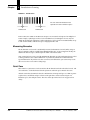
The X Dimension 4-1
Measuring Barcodes 4-2
Quiet Zone 4-2
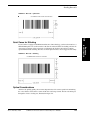
Quiet Zones for Stitching 4-3
Optical Considerations 4-3
Depth of Field 4–4
Optical Throw 4–4
Reading Range 4–4
Height of Scan 4–4
Scan Angle 4–4
Barcode Orientation 4-5
Ladder 4–5
Picket Fence 4–6
Tilt 4–7
Pitch 4–8
Skew 4–8
Number of Scans per Barcode 4-8
Presence Detection 4-9
Single Presence 4–9
Zone Presence 4–10
Gap Tracking 4-11
Additional Inputs 4–13
X & Y Coordinates 4–15
CIX Technology & Barcode Requirements 4-16
Processing Barcode Data 4-19
Data Transmission 4–19
When Output Message is Sent 4–20
Introduction to Scan Tunnel Applications 4–21
CiMAX 7800 Scanning Front/Back Boxes 4-21
CiMAX 7800 Scanning Front, Back, Top & Side Boxes 4–23
Rev F, February 2002
CiMAX 75xxA/76xx Scanner Technical Reference Manual
ix
Contents
CiMAX 7850 Scanning Bottoms of Boxes
Scan Tunnel Control 4–24
Interface Units 4–24
Additional Information 4–24
CHAPTER 5
Startup & Operation
4-23
5–1
Serial Communications Ports 5–1
Power Up 5-1
Status Messages 5–1
Power-Up With Factory Default Values 5–4
Power-Up After Memory Failure 5–4
Memory Error Detection, Response & Reporting 5–4
Power-Up With Customized Values 5–5
Power-Up After Automatic Reboot 5–5
User Interface—Parameters & Diagnostics 5-5
Operating Modes 5-5
Normal Mode 5–6
Setup & Diagnostic Modes 5–6
Resetting to Default Parameters 5–6
Terminal Types 5-7
Non-Intelligent ASCII Terminal 5-7
Setup Menu on the ASCII Terminal 5–7
Data Entry through Setup Menu on the ASCII Terminal 5–8
Diagnostics Menu Display on the ASCII Terminal 5–9
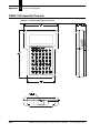
CiMAX 1400 Hand-Held Terminal 5-10
CiMAX 1400 Hand-Held Terminal Function Keys 5–11
Special-Use Alpha Keys on the CiMAX 1400 Hand-Held Terminal 5–11
Using the Hand-Held Terminal as a Real Time Display 5–12
CiMenu32 for Windows Utility (Optional)
5–12
CiMenu32 Features 5-13
System Requirements 5-13
CHAPTER 6
Host Commands & Downloads
Introduction 6–1
Control Commands from the Host
6–1
6–1
ASCII 4 Command—Requesting a Diagnostic String 6-3
ASCII 5 Command—Requesting Status Information 6-4
Status String Digit Explanations 6–4
ASCII ; Command—Rebooting Scanner 6-7
ASCII < Command—Clearing Diagnostic Count 6-8
ASCII = Command—Enabling Relay Control Outputs 6-9
ASCII > Command—De-Energizing Relay Control Outputs 6-10
ASCII ? Command—Setup 6-11
Downloading Individual Parameters 6–11
Downloading Groups of Parameters 6–12
Uploading Groups of Parameters 6–12
Uploading All Group Setup Strings at Once 6–13
Set Time & Date Command 6–13
ASCII A or Greater Command—User Program Data 6-14
x
CiMAX 75xxA/76xx Scanner Technical Reference Manual
Rev F, February 2002
Contents
~TOTAL~ Command 6-15
~DATA~ Command 6-16
~TOT00~ Command 6-17
~!~ & ~$~ Commands 6-18
~LASxx~ Command 6-19
~QSNDx~, ~QGETx~ & ~QFLS~ Commands
~VER~ Command 6-21
Gap Tracking Diagnostic Commands 6-22
6-20
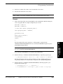
C Program Control Commands 6–23
Upload C Programs to the Host Computer (ASCII 91) Command 6-23
Erase C Program (ASCII 92) Command 6-23
Stop C Program (ASCII 93) Command 6-23
Suspend C Program (ASCII 94) Command 6-23
Resume C Program (ASCII 95) Command 6-24
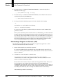
C Programming Considerations
6–24
Compiling C Programs for Download 6-24
Installing C Programming Platform 6–24
Downloading C Programs (.sef) 6–24
Downloading C Programs via Starnode (.LAN) 6–26
Downloading .LAN Files—Starnode Asynchronous Controller MUX Interface 6–29
Data Detection by C 6–29
Polling 6-29
Event Manager 6-30
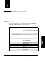
CHAPTER 7
Communication Modes
7–1
OPMODE Parameter 7–1
Scale Mode 7–2
Starnode Usage 7–2
RS-422 Mode 7–2
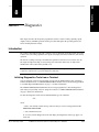
CHAPTER 8
Diagnostics
8–1
Introduction 8–1
Initiating Diagnostics Tests from a Terminal 8-1
Diagnostics Menu 8-2
Diagnostic Tests & Procedures 8-3
Stopping Diagnostic Tests 8–3
Read Speed Test 8–3
Read Quality Test 8–4
Read Efficiency Test 8–5
Minimum/Maximum Bar Test 8–6
Motor Speed Test 8–7
Input/Output (IOPRTS) Test 8–8
Label Position Test 8–8
Tachometer Status Test 8–9
Tachometer Calibration Procedure 8–9
Set Digital Potentiometers 8–11
Decoder Processor Test (CIDSP DIAGS) 8–12
Can Diagnostics (75xxA Only) 8–12
Exhaustive RAM Test 8–13
Rev F, February 2002
CiMAX 75xxA/76xx Scanner Technical Reference Manual
xi
Contents
Flash Operating System Download 8–14
Restore Keysheet 8–17
Restore C Program 8–18
Set Clock Procedure 8–20
7555A/7655 Frequency Adjustment 8-21
Gap Tracking Diagnostics
8–22
Scanner Model Notification 8-22
Gap Tracking Parameters 8-22
Setting Up for Gap Tracking Diagnostics 8–23
Unsolicited Messages Sent to the Setup Port 8–23
Host Commands 8-24
~TRACK~ 8–24
~TRAKS~ 8–27
~TRAKN~ 8–27
~TRUNC~ 8–27
~TIMES~ 8–27
~TOLER~ 8–27
~TOTAL~ 8–28
~DATA~ 8–28
~TOT00~ 8–29
NORMMD_RPT Data Reports & Formats 8–29
Position Accuracy Factors 8–32
CIX Troubleshooting 8–34
Host Commands 8-34
Recording 8-34
Playback 8-35
APPENDIX A
Group Setup Strings
A–1
Group Setup String Definitions A–1
Group Setup Parameter String Formats
A–2
Scanner Operation Parameters A-3
General Decoding Parameters A-3
Histogram Parameters A-3
Decode Format Parameters A-4
Match Strings Parameters A-4
Decoding Processor (DSP) Parameters A-5
DSP Autosetup Parameters A-6
Host & Terminal Port Serial Communications Parameters A-7
Lan Port Comms & Messages Parameters A-7
Digital Potentiometers (Parameters 444-459) A-8
Digital Jumpers Parameters A-8
Presence Inputs, Relay Types & Debounce Times Parameters A-9
Relay Outputs Parameters A-9
User Program Parameters A-10
User Variables Parameters A-10
Gap Tracking & Tachometer Input Parameters A-11
Height Detect Parameters A-12
Label Tracking A-12
xii
CiMAX 75xxA/76xx Scanner Technical Reference Manual
Rev F, February 2002
Contents
APPENDIX B
ASCII Equivalence
B–1
ASCII Equivalence Table B–1
APPENDIX C
Dimension Diagrams
C–1
CiMAX 7500A Scanner C–1
CiMAX 7555A Scanner C–2
CiMAX 7600 Scanner C–3
CiMAX 7650/7655 Scanner C–4
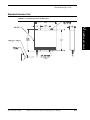
Standard Interface Unit C–5
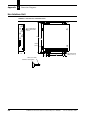
Hex Interface Unit C–6
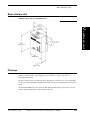
Basic Interface Unit C–7
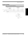
Photoeye C–7
Photoeye Tree Bracket C–9
Photoeye Tree Hardware C–10
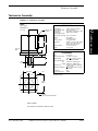
Tachometer Assembly C–11
CiMAX 1400 Hand-Held Terminal C–12
Index
Rev F, February 2002
Index–1
CiMAX 75xxA/76xx Scanner Technical Reference Manual
xiii
Contents
xiv
CiMAX 75xxA/76xx Scanner Technical Reference Manual
Rev F, February 2002
Preface
Welcome
PREFACE
Congratulations on your purchase of the CiMAX 75xxA/76xx Scanner. Our goal at SICK Auto
Ident, Inc. is to provide you with a reader/control system of the highest quality that is both powerful
and easy to use. We are also committed to providing you with excellent technical and customer
support services necessary to meet your business needs. We’re glad to have you as a customer and
we’re sure you’ll be pleased with your purchase.
The CiMAX 75xxA/76xx Scanner uses advanced laser technology to locate and read 1-D
symbologies, linear barcodes and to automatically decode in any orientation. It provides high-speed
accuracy reading of coded information to meet your real-time requirements.
How To Use This Manual
The purpose of this manual is to ensure that your CiMAX 75xxA/76xx Scanner system becomes
operational quickly and reliably. This manual covers installation, basic operations, including
detailed step-by-step instructions to operate the CiMAX 75xxA/76xx Scanner system, and
supporting information.
Guide Conventions
The following typographical conventions are used throughout this manual.
•
Items emphasizing important information are italicized or bolded.
•
Keyboard entries are indicated as an italic.
•
Menu selections, menu items, tab selections, and entries in screen image windows are
indicated as such: File, Data Matrix, Options.
Note: Provides useful information about the current topic.
Caution: Provides information for the prevention of damage to the product.
WARNING! PROVIDES INFORMATION FOR THE PREVENTION OF PERSONAL
INJURY OR DAMAGE TO THE PRODUCT.
Rev F, February 2002
CiMAX 75xxA/76xx Scanner Technical Reference Manual
xv
Preface
Warning Symbols
Class 2 Laser Product
Laser Classe 2
Klasse 2 laserscanner
Laser Klasse 2 Produkt
Producto Láser Clase 2
Luokan 2 laserlaite
Apparecchiatura laser di classe 2
Laser Radiation - Do not stare into Beam.
Rayonnement Laser - Ne pas s’exposer.
Radiación Láser - No mirar fijamente a el rayo.
Laser straling - Niet in straal kijken.
Laserstrahlung - Nicht in den Strahl blicken, auch nicht mit optischen Instrumenten.
Lasersäde - Alä katso valolähteeseen.
Radiazioni laser - Non rivolgere lo sguardo direttamente al raggio laser.
Caution - Laser radiation when open and interlock defeated. AVOID EXPOSURE TO BEAM.
Attention - En cas d’ouverture, risque de rayonnement laser. NE PAS S’EXPOSER.
Peligro - Radiación Láser al abrir. EVITAR LA EXPOSICIÓN DEL RAYO.
Waarschuwing - Bestraling mogelijk bij geopend en ontgrendeld toestel. BLOOTSTELLING AAN LASERSTRAAL
VERMIJDEN!
Vorsicht! Laserstrahlung wenn Abdeckung geöffnet oder Sicherheitsschalter überbrückt. NICHT IN DEN STRAHL
BLICKEN.
Varoitus - Lasersäteilyä saattaa esiintyä avattaessa kotelo ja ohitettaassa suojakytkimet. VÄLTÄ ALTISTUMISTA
LASERSÄTEILYYN.
Attenzione - Radiazioni laser in caso di apparecchiatura aperta e dispositivo di protezione difettoso. EVITARE OGNI
ESPOSIZIONE AL RAGGIO LASER.
Warning - Shock hazard
Danger - Haute tension
Atención - Peligro de descarge
Waarschuwing - Schokgevaar
Warnung! Vorsicht Hochspannung
Sähköiskun vaara
Attenzione - Pericolo di scossa elettrica
Caution
Attention
Peligro
Waarschuwing
Vorsicht
Varoitus
Attenzione
xvi
CiMAX 75xxA/76xx Scanner Technical Reference Manual
Rev F, February 2002
Preface
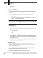
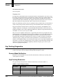
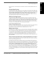
Warning Labels
This scanner is labeled in accordance with Federal regulations. If any label is removed, lost, or
becomes illegible, order a replacement from SICK Auto Ident, Inc. Figure 1, Figure 2, and Figure 3
show the labels and their locations on the scanner.
FIGURE 1.
Warning Label Location
Front 7500A/7600
LASER LIGHT
AVOID DIRECT
EXPOSURE
Rev F, February 2002
Side 7550A/7650/7655
Laser Radiation
Do Not Stare
Into Beam
CiMAX 75xxA/76xx Scanner Technical Reference Manual
xvii
Preface
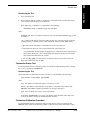
FIGURE 2.
Warning Label Location—Rear
COMPLIES WITH 21 CFR
1040-10 AND 1040-11
xviii
CiMAX 75xxA/76xx Scanner Technical Reference Manual
Rev F, February 2002
Preface
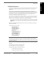
FIGURE 3.
Warning Labels—Inside Interface Unit
Attention - déconnecter l’alimentation principale avant d’ouvrir le couvercle.
Atención - Desconectar la alimentación de corriente antes de retirar esta cubierta.
Waarschuwing - Netspanning uitschakelen vooraleer de behuizing te openen.
Warnung! Vor dem Öffnen des Gehäuses Netestecker ziehen.
Varoitus - Kytke jännite pois ennen tämän kannen poistamista.
Attenzione - Scollegare le principale alimentazione prima de rimiovere questo coperchio.
Attention - une alimentation peut être présente en provenance d’une source externe connectée à
cet equipement. Avant intervention, verifier que l’alimentation est débranchée.
Peligro - Equipo con tensión. Verificar que esté desconectado antes de manipularlo.
Waarschuwing - Mogelijke stroomtoevoer teweeggebracht door externe aansluiting(en).
Uitschakeling netspanning nakijken vóór ingebruikname.
Vorsicht! Spannung kann von extern angeschlossenen Geräten zu diesem Gerät übertragen
werden. Vor dem Service auf Spannungsfreiheit prüfen.
Varoitus - Laitteeseen saattaa tulla jännite ulkopuolisista lähteistä. Ennen huoltoa tarkista, että
laite on kytketty irti muista laitteista.
Attenzione - In questa apparecchiatura può esservi corrente proveniente dall’esterno. Prima di
effettuare qualsiasi riparazione verificare che i circuiti siano prima stati esclusi.
Rev F, February 2002
CiMAX 75xxA/76xx Scanner Technical Reference Manual
xix
Preface
CDRH Requirements
The following CDRH Requirements must be met.
Levels of Accessible Laser Radiation
670 nm, 2.0 mw peak, 0.21 mw average, 36 msec pulse, .10 micro sec. rise/fall
3.3 ms rate, 0.55 micro joule pulse radiation.
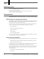
Getting Assistance
We hope this manual will be helpful. If you have questions or comments, please don’t hesitate to
contact SICK Auto Ident, Inc. For additional assistance, please refer to the following information.
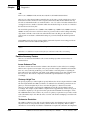
SICK Auto Ident, Inc. Customer Service Policy
We care about your productivity and will go to great lengths to ensure that you have maximum uptime. Whether you call for a site survey, place an order, or request technical support, you are
assured of prompt, courteous, and personalized attention.
Our state-of-the-art accounting and computer management systems permit us to instantly access
customer order information. A trained staff member is available to assist you with:
•
Order entry assistance
•
Product information and application answers
•
Product delivery status
•
Technical support
•
One-on-one problem resolution
Contact your sales representative. Or, to reach SICK Auto Ident, Inc. Customer Service directly,
call 1-888-264-4641. The fax number is (781) 828-3150.
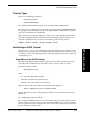
Return-to-Factory Instructions
Should your CiMAX 75xxA/76xx Scanner system fail to operate correctly, verify the following:
•
Confirm that it has been properly configured with the proper setup parameters, as ordered.
•
Inspect and verify all cable connections.
If a problem persists, contact your sales representative or SICK Auto Ident, Inc. Customer Service
by calling the numbers provided in “SICK Auto Ident, Inc. Customer Service Policy”.
Please call SICK Auto Ident, Inc. at 1-888-264-4641 to return a CiMAX 75xxA/76xx Scanner for
repair. Request the Return Authorization (R.A.) Department. Please be prepared to furnish the
following information:
xx
•
Company name, address, and telephone number
•
Contact name
CiMAX 75xxA/76xx Scanner Technical Reference Manual
Rev F, February 2002
Preface
•
Return address (if different) and other pertinent shipping information
•
Catalog number and serial number
•
Description of the problem
•
Purchase order and other invoicing information relative to the repair
SICK Auto Ident, Inc. will provide you an R.A. number. Please include this R.A. number on the
shipping label and any correspondence concerning the return. Please include several sample
barcode labels, a listing of setup parameters, and a detailed description of the problem. Repair or
upgrade estimates shall be furnished upon request.
Upon receiving a defective product with a valid Return Authorization number, SICK Auto Ident,
Inc. will attempt to return the repaired or replacement equipment on a best-effort basis within five
working days. You may have a different support plan specifying other terms.
For critical applications, SICK Auto Ident, Inc. recommends you keep a spare scanner on hand for
immediate replacement. Alternatively, you can select a support plan, which specifies a quick
response time or a scanner swap.
SICK Auto Ident, Inc. shall pay surface transportation charges for the return shipment if the address
is within the 48 contiguous states or the District of Columbia. Customers outside this area shall pay
shipping costs, customs clearance, and any other related charges.
Your scanner will be returned after inspection and repair. However, upon return, the scanner may
require re-configuration to the setup parameter values you were using.
Product Warranty
SICK Auto Ident, Inc. guarantees that its products are free from defects in materials or
workmanship (under proper and normal use and maintenance) in accordance with SICK Auto
Ident, Inc.' operating instructions for a period of one year from the shipping date.
This warranty shall be null and void if equipment is modified, if it is improperly installed or used, if
it is damaged by accident or neglect, or if components are improperly installed or replaced by the
buyer.
Under no circumstances shall SICK Auto Ident, Inc. be liable to the buyer or any other party for
lost profits, diminution of good will, or other special or consequential damages whatsoever.
The warranty appearing here supersedes all other warranties, express or implied, statutory or
otherwise, including any implied warranty of merchantability or fitness for a particular purpose.
Rev F, February 2002
CiMAX 75xxA/76xx Scanner Technical Reference Manual
xxi
Preface
xxii
CiMAX 75xxA/76xx Scanner Technical Reference Manual
Rev F, February 2002
1
Overview &
Maintenance
1
Overview & Maintenance
CHAPTER 1
This chapter provides you with an overview of a typical CiMAX 75xxA/76xx scanner application
product specifications.
Overview
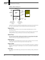
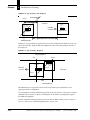
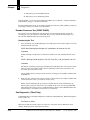
Typical Physical Setup
CiMAX 75xxA/76xx scanners may be used with other equipment including photoeyes, tachometer,
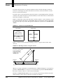
Standard Interface Unit, and a Hex Interface Unit. Figure 1–1 shows the CiMAX 7500A scanner in
a typical scan tunnel configuration with accessory components. However, your application may not
have the same requirements. Specific cable connections, pinouts and wiring diagrams are provided
in Chapter 3, “Controls, Connectors, & Indicators”.
FIGURE 1–1.
Typical Configuration—CiMAX 7500A/7600
B o x M o vin g o n
C o n ve y o r
R e fle c to r
Reflector
C iM A X
7500A
S c anner
Photoeye
P ho
to e ye
(upstream of scanner)
(up s tre a m o f
s c a nne r )
Inte
rfa cUnit
e U nit
Interface
Rev F, February 2002
CiMAX 75xxA/76xx Scanner Technical Reference Manual
1-1
Chapter
1
Overview & Maintenance
CiMAX 7500A/7600 Laser Scanner
The 75xxA/76xx scanners are intelligent fixed-position laser scanners designed for high reading
rates, local or network processing and control and user C programmability. Optionally, it can be
configured with SICK Auto Ident, Inc. CIX (Code Information eXtraction) technology to permit
barcodes rotated as much as 60° from the scan beam to be read. A network option (Ethernet, SDS,
or DeviceNet) is also available with 75xxA scanners.
The dual processor architecture uses an independent Digital Signal Processor (DSP), to translate
barcode data for the 32-bit main processor. The CiMAX 75xxA/76xx scanners can be configured
with up to 1MB of non-volatile program and data memory.
The CiMAX 75xxA/76xx scanners have eight inputs and eight outputs for use in box presence and
height detection, timing, diverter control, and alarming. The Standard Interface Unit provides
power for one scanner; or two, when operated in Master/Slave mode. The Basic Interface Unit only
provides power for one CiMAX 76xx, or one CiMAX 75xxA without the Ethernet option installed.
The CiMAX 7600 scanner is operationally identical to the 7500A except that the network option is
not available. The CiMAX 7600 case is an inch narrower (3.32" vs. 4.33") than that of the CiMAX
7500A, so the CiMAX 7600 can be mounted in more physically restricted spaces.
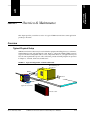
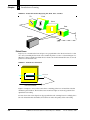
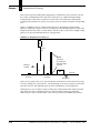
CiMAX 7550A/7650 Laser Scanner
The CiMAX 7550A/7650 scanners are electrically and operationally identical to the CiMAX
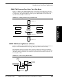
7500A/7600. The housing of the CiMAX 7550A/7650 is physically longer than the CiMAX 7500A
to accommodate a 90° deflection mirror, which permits the laser beam to output from the side
instead of the front of the case, as shown in Figure 1–2.
FIGURE 1–2.
CiMAX 7650 Scan Sweep
This design allows for a flatter installation. For example, it can be installed under a conveyor to
scan labels on the bottom of a box. It is sometimes used to scan picket-fence orientation barcodes
or the bottom of boxes as they pass over a break in the conveyor. The cable connectors may be
positioned to face up or down, and the mounting screws are located on the side of the unit.
1-2
CiMAX 75xxA/76xx Scanner Technical Reference Manual
Rev F, February 2002
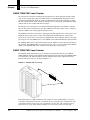
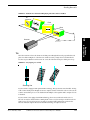
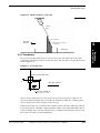
CiMAX 7555A/7655 Laser Scanner
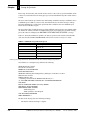
The CiMAX 7555A/7655 emits a horizontal beam that is swept back and forth in a sweep raster
scanning pattern as shown in Figure 1–3.
FIGURE 1–3.
Sweep Raster Scan Pattern of the CiMAX 7555A/7655
Scan
Height
Sweep
Height
The CiMAX 7555A/7655 sweep raster scanner provides a moving, visible red laser beam that
sweeps repeatedly across a barcode in a regular sinusoidal wave pattern. The CiMAX 7555A/7655
has the same housing as the CiMAX 7550A/7650, but the laser beam is deflected in a sweep raster
pattern for increased coverage.
Refer to Appendix C, “Dimension Diagrams” for mechanical drawings of the CiMAX 7500A, the
CiMAX 7550A, the CiMAX 7600, and the CiMAX 7650/7655.
Except where specifically noted, all information in this manual applies to the
CiMAX 7500A/7550A/7555A/7600/7650/7655 Scanners.
Keysheet
The Keysheet specifies the details of your scanner setup. It is based on information you provided to
SICK Auto Ident, Inc. about your scanner application. The keysheet has been carefully developed
from the results of a questionnaire you filled out about your conveyor system.
The information in the keysheet customizes the CiMAX 75xxA/76xx scanner hardware and
software setup for your site. Do not deviate from the keysheet or otherwise change the
configuration without consulting SICK Auto Ident, Inc.
Software Updates
Software updates from SICK Auto Ident, Inc. can include changes and improvements in the
following:
•
Rev F, February 2002
Operating System
CiMAX 75xxA/76xx Scanner Technical Reference Manual
1-3
1
Overview &
Maintenance
Overview
Chapter
1
Overview & Maintenance
•
CIX Technology
•
Network
•
File Memory
•
C code
•
Decoded Symbologies
Software updates will be provided to you by SICK Auto Ident, Inc. as your application requires.
These updates can be uploaded into your scanner from your PC, with the software available from
SICK Auto Ident, Inc. on a diskette. The scanner uses flash memory to allow complete
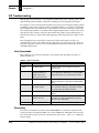
re-programming in the field.
Specifications
Scanner
Configuration
Depth of Field (DOF)/Diodes
•
Fixed focus: 4”, 8”, 14”, 18”, 26.5”, 28”, 36”
Memory
•
256K (approx. 100K for user C programs and data)
•
1M (approx. 800K for user C programs and data)
Network—75xxA only
•
Without
•
Ethernet 10 base 2
•
Ethernet 10 base T
•
SDS
•
DeviceNet
Physical
For mechanical drawings with dimensions, refer to Appendix C, “Dimension Diagrams”.
CiMAX 7500A
1-4
•
5.71 x 4.33 x 4.55 inches (145 x 110 x 115 mm)
•
3.5 pounds (1.6 kilograms)
CiMAX 75xxA/76xx Scanner Technical Reference Manual
Rev F, February 2002
CiMAX 7550A/7555A
•
5.70 x 4.78 x 6.85 inches (145 x 121 x 174 mm)
•
4.0 pounds (1.8 kilograms)
CiMAX 7600
•
5.71 x 3.32 x 4.55 inches (145 x 85 x 115 mm)
•
3.0 pounds (1.4 kilograms)
CiMAX 7650/7655
•
5.71 x 3.32 x 6.08 inches (145 x 85 x 155 mm)
•
3.5 pounds (1.6 kilograms)
Method of Illumination
Laser diodes, wavelength 670 nanometers (visible red light)
Scan Rates
•
Application dependent—Refer to your keysheet
•
400-1200 scans per second @ 60o scan angle
Power
•
Input
–
Power required from external Basic Interface Unit. Regulated +12 VDC, 1.2A max.
–
Power required from Standard/Hex Interface Unit. +12 VDC, 1.0A, +5 VDC, 250 mA.,
max.
Construction
Single integrated package consisting of aluminum enclosure fully gasketed and mounted on
1/2-inch (12.7 mm) aluminum base plate.
Environmental
•
NEMA 12 (IP 65) dust-tight and drip-proof
•
Operating Temperature—32° to 122° F. (0o to 50o C)
•
Humidity—5% to 95% non-condensing
LED Status Indicators
Six LEDs on a single display monitor operations and communications
Rev F, February 2002
CiMAX 75xxA/76xx Scanner Technical Reference Manual
1
Overview &
Maintenance
Specifications
1-5
Chapter
1
Overview & Maintenance
Communications
Four independent communications ports
•
1 asynchronous serial Host port (RS-232 or RS-422)
•
1 asynchronous serial Terminal port (RS-232)
•
1 RS-485 LAN port with Starnode protocol
•
1 Network port (optional) - CiMAX 75xxA only
Inputs
•
Fifteen total, active low when <1.0 VDC
–
•
Eight standard inputs
–
–
•
Maximum input 30 VDC intermittent, 27 VDC continuous
Normal default input assignments
-
Two presence (Inzone, Outzone)
-
One tachometer—0.2 inches per pulse minimum resolution at up to 1000 pulses
per second, max
-
Up to five height-sensing inputs
Inputs not used for presence, tachometer and height-sensing are available for general
purpose use under user C program control
Seven optional inputs—For use only for height-sensing with Programmable Interface
Controller
Outputs
•
Eight total, open collector solid state—30 VDC at 150 mA, max
•
Normal default output assignments
–
Output 1—No Read
–
Output 2—Match
–
Output 3—No Match
Basic Interface Unit
Physical
Refer to Appendix C, “Dimension Diagrams” for more information.
1-6
•
3.64 H x 4.13 W x 1.39 D inches (93 x 105 x 35 mm)
•
1.6 lbs (0.73 kg) with attached cable
CiMAX 75xxA/76xx Scanner Technical Reference Manual
Rev F, February 2002
•
Scanner-interface cable length—6.5 feet (2 meters)
•
Power cord length—15 feet (4.6 meters)
AC Power
115/230 ±10% VAC @ 0.4/0.2A, 50/60 Hz.
Inputs
Basic—One solid state, active low when <1.0 VDC, 30 VDC max, 27 VDC continuous
(This input is an extension of scanner input 1, default INZONE PRESENCE signal)
Outputs
•
Basic—One open collector solid state, 30 VDC at 150 mA, max. (This output is an extension
of scanner output 1, default NO READ signal)
•
+12 VDC and ground to operate external photoeye
•
RS-232 serial communications link to host computer
Standard Interface Unit
Physical
Refer to Appendix C, “Dimension Diagrams” for more information.
•
13.25 H x 13.00 W x 2.98 D inches (337 x 330 x 76 mm)
•
13.5 lbs (6.1 kg) with attached cable
•
Scanner-interface cable length—6.5 feet (2 meters)
AC Power
115/230 ±10% VAC @ 0.8/0.4A, 50/60 Hz.
Inputs
Standard—Eight solid state, active low when <1.0 VDC, 30 VDC max, 27 VDC continuous
(These inputs are extensions of the eight solid state scanner inputs)
Outputs
Standard—Eight open collector solid state, 30 VDC at 150 mA, max. (These outputs are extensions
of the eight solid-state scanner outputs)
Optional Solid-State Input/Output Modules
Optically isolated Opto–22 style modules may be installed as inputs or outputs. They are controlled
by standard input/output signals.
•
Input Modules
–
Rev F, February 2002
Type—AC Input
CiMAX 75xxA/76xx Scanner Technical Reference Manual
1
Overview &
Maintenance
Specifications
1-7
Chapter
1
Overview & Maintenance
–
•
Voltage Range—90-140 VAC
-
6 mA at minimum voltage
-
10 mA at max. voltage
Output Modules
–
Type—AC Output
–
Load Current Over Load Voltage Range—0.02 - 3 A at 24 - 140 VAC
Electro-Mechanical Output Relay
One Form C (SPDT) relay operated by scanner output eight.
Hex Interface Unit
Physical
For dimensions, refer to Appendix C, “Dimension Diagrams”.
•
21 H x 18.5 W x 4.25 D inches (533 x 470 x 108 mm)
•
50.5 lbs (22.9 kg) with attached cable
•
Scanner-interface cable length—6.5 feet (2 meters)
AC Power
115/230 VAC +10% @ 3.0/1.5A, 50/60 Hz.
Inputs
Standard—Eight solid state, active low when <1.0 VDC, 30 VDC max, 27 VDC continuous
(These inputs are extensions of the eight solid state scanner inputs)
Outputs
•
Standard—Eight open collector solid state, 30 VDC at 150 mA, max. (These outputs are
extensions of the eight solid-state scanner outputs).
Optional Solid-State Input/Output Modules
Optically isolated Opto–22 style modules may be installed as inputs or outputs. They are controlled
by standard input/output signals.
•
1-8
Input Modules
–
Type—AC Input
–
Voltage Range—90-140 VAC
-
6 mA at minimum voltage
-
10 mA at max. voltage
CiMAX 75xxA/76xx Scanner Technical Reference Manual
Rev F, February 2002
•
Output Modules
–
Type—AC Output
–
Load Current Over Load Voltage Range—0.02 - 3 A at 24 - 140 VAC
Electro-Mechanical Output Relay
One Form C (SPDT) relay operated by scanner output eight.
Maintenance
The scanner requires no special preventive maintenance when operated in an environment free
from extremes of temperature, humidity, shock, and vibration.
The following tasks should be performed once a month to keep the scanner clean and to inspect it
for mechanical damage.
1.
Remove DC power and disconnect all cables before cleaning.
2.
Clean dirt and dust from the scanner's window and from the LED display, using a soft, lint-free
cloth and a non-abrasive liquid cleaner. DO NOT use an abrasive cleaner.
3.
Check all cables for signs of abrasion.
4.
Check that all cable connections are secure after maintenance.
Caution: The scanner's internal components do NOT require preventive maintenance.
Opening the scanner with power applied can expose the operator to electrical and mechanical
hazards, which can cause bodily injury. If internal maintenance is required, return the
scanner to SICK Auto Ident, Inc. for service.
Rev F, February 2002
CiMAX 75xxA/76xx Scanner Technical Reference Manual
1
Overview &
Maintenance
Maintenance
1-9
Chapter
1-10
1
Overview & Maintenance
CiMAX 75xxA/76xx Scanner Technical Reference Manual
Rev F, February 2002
2
Installation & Setup
2
Installation & Setup
CHAPTER 2
This chapter provides you with an overview of the CiMAX 75xxA/76xx scanner hardware
installation and setup. It also describes the procedure for mounting the scanner and
interconnections to the interface unit, photoeyes and tachometer.
Unpacking & Inspection
Unpack the scanner and any accessories ordered. Depending on what you ordered, the equipment
may have been shipped in more than one carton.
Remove the packing list from the pocket on each carton. Verify that you have received all of the
items shown on the packing lists.
Inspect the equipment for shipping damage and, if you see any damage, notify both the carrier and
SICK Auto Ident, Inc. immediately.
Store the original packing material inside each carton, and store the cartons in a safe place. If the
scanner or any accessories need to be repaired, upgraded or modified in the future, return them to
SICK Auto Ident, Inc. in the original cartons with the original packing material.
Refer to “Product Warranty” on page xix and “Return-to-Factory Instructions” on page xviii for
more information.
Installation Checklist
•
Plan and schedule complete installation
•
Identify and include personnel responsible for:
•
Rev F, February 2002
–
Scanning system
–
Data system
–
Control or conveyor system
–
Maintenance
–
Installation
Review plan with SICK Auto Ident, Inc. Field Service Engineer—Confirm schedule two
weeks prior to engineer arriving on site for functional checkout
CiMAX 75xxA/76xx Scanner Technical Reference Manual
2-1
Chapter
2
Installation & Setup
Site Preparation
Refer to the keysheet.
•
Scanner
•
AC power to Interface Unit. Ensure AC power is connected to an earth ground.
•
AC power (convenience outlets) for local PC, CRT, modem, oscilloscope. Ensure AC power is
connected to an earth ground.
•
Structure for mechanically installing scanner
•
Interface unit
•
Tachometer, if used, including custom mounting brackets and flexible shaft coupling for
required mechanical isolation
•
Photoeyes
–
Presence
–
Height-sensing, if used, including mounting brackets
•
Setup/Diagnostic Terminal—CiMAX 1400, local CRT, or PC running serial communications
software program, i.e., Microsoft Windows Terminal, ProComm or Telix.
•
Telephone for support
•
Telephone line for support modem
•
Verify conveyor speeds and width
•
Verify box height variations
•
Verify label symbology, dimensions and quality
•
Verify all parts, mounting brackets, cables, connectors, and personnel available
Physical Installation
•
Supporting structure for scanner with provisions for exact positioning
•
Interface Unit
•
Hex Interface Unit, if installed
•
Tachometer. brackets and shaft isolation, provided by installer, are important.
•
Photoeyes—Exact Positioning Is Critical!
•
2-2
–
Presence
–
Height-sensing
Modem
CiMAX 75xxA/76xx Scanner Technical Reference Manual
Rev F, February 2002
Installation Checklist
Electrical Connections
•
2
To Scanner
–
Network (if used)
–
I/O cable to interface unit (DC power)
Installation & Setup
•
To Interface Unit
–
Grounded AC power
–
I/O cable to scanner
–
Presence photoeyes
–
Tachometer (installer provides cable)
–
Height-sensing photoeyes
–
Communication cable(s) provided by installer
–
Any special digital I/O connections
–
Modem and cables, provided by installer
On Site Testing
On site testing with SICK Auto Ident, Inc. Field Service Engineer or SICK Auto Ident, Inc.Certified Installer. Plan for one day per scanner plus 1/2 day for training.
•
Review operational requirements
•
Review mechanical and electrical installation
•
Functional Reading Tests
–
Diagnostics
–
Read Labels
-
Known good from SICK Auto Ident, Inc.
-
Customer labels
-
Field Service Diagnostic Test Kit
-
Basic Tests
-
Over extremes of label placement
•
Set or verify photoeye placement parameters
•
Run Tachometer Diagnostic—automatically sets some setup parameters
•
Verify communications and special I/O circuits
–
Rev F, February 2002
To customer device
CiMAX 75xxA/76xx Scanner Technical Reference Manual
2-3
Chapter
2
Installation & Setup
–
If necessary, transmit to known good device (PC running communications software
program)
–
Through modem to remote site for support
–
Ethernet, if used, directly to scanner connector
•
Test application
•
Repeat with spare equipment
Operation Instruction
Instruct user personnel in operation of product.
•
Manual with keysheet
•
LED Displays
•
Operation
•
Setup parameters
•
Diagnostics
•
Troubleshooting
•
Label quality
•
Communications and special I/O circuits
•
Modem
•
Selected support plan
•
Other support alternatives
Final Approval
•
User/customer sign-off on installation checklist. Copy and file.
•
Update keysheet or other documentation as necessary for future reference
Site Preparation
Power
When installed, the Interface Unit will require a dedicated AC outlet. You should provide
additional 115 VAC outlets near the Interface Unit for setup and diagnostic test equipment.
+12VDC and +5VDC regulated DC power is provided by the Standard/Hex Interface Unit.
+12VDC regulated DC power is provided by the Basic Interface Unit.
2-4
CiMAX 75xxA/76xx Scanner Technical Reference Manual
Rev F, February 2002
Site Preparation
Setup
In addition to the components illustrated in Figure 1–1, “Typical Configuration—CiMAX
7500A/7600” on page 1-1, you should have one of the following:
CiMAX 1400 hand-held terminal
•
PC computer with terminal emulation software and cable
•
RS-232 ASCII terminal
Installation & Setup
•
2
Communications wiring to the host is necessary.
Photoeyes & Tachometer Installation
Follow the installation directions only if your system requires presence photoeyes, height-detecting
photoeyes and a tachometer.
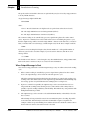
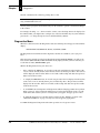
Installing the Tachometer
A tachometer is required to measure conveyor movement for gap tracking. Refer to “Gap
Tracking” on page 4-11 for more information. Gap tracking is required when there is the possibility
that more than one box may be in the scanning zone at the same time.
You must provide a custom bracket to mount the tachometer securely to your conveyor.
Connect the tachometer to a driven roller or other driven rotational part of your conveyor using a
flexible shaft coupling or a belt and pulley drive as shown in Figure 2–1.
FIGURE 2–1.
Tachometer Driver by Flexible Shaft Coupling
Tachometer Housing
Shaft Coupling
Note: You must use an appropriate flexible shaft coupling or belt and pulley drive to provide
mechanical isolation of the tachometer from your conveyor. Without such isolation, the tachometer
is subject to misalignment, roller shaft wobble and consequent wear to the tachometer's precision
bearings.
Alternatively, a friction wheel can be used, to couple the tachometer to the surface of a belted
conveyor. Friction drives have the potential to slip and cause tracking errors over time, but may be
suitable for your application.
A suitable measuring wheel (P/N 16002070215) with a 12" circumference, a white rubber surface
and an inside diameter compatible with the standard SICK Auto Ident, Inc. tachometer, and a
universal tracking mounting base (P/N 14005750000), can be purchased from:
Rev F, February 2002
CiMAX 75xxA/76xx Scanner Technical Reference Manual
2-5
Chapter
2
Installation & Setup
Danaher Controls
1675 Delany Road
Gurnee, IL 60031
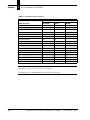
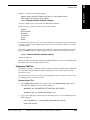
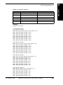
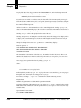
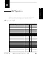
The CiMAX 75xxA/76xx scanner requires inputs from a tachometer that produces a conveyor
travel resolution finer than 0.20 inches per pulse with a pulse rate of no more than 1 kHz. Lower
resolution will affect position accuracy but may provide enough accuracy for your application.
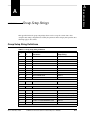
The examples in Table 2–1 display conveyor travel per pulse if a 300-pulses/revolution tachometer
is driven directly from conveyor rollers of the diameters indicated. The speeds listed produce 1 kHz
pulse rates.
TABLE 2–1. Conveyor
Travel per Pulse
Roller diameter:
2 inches
3 inches
4 inches
Resolution:
0.021 inches
0.031 inches
0.042 inches
Conveyer Speed:
21 inches/sec
31 inches/sec
42 inches/sec
105 ft/min.
157.5 ft/min.
210 ft/min.
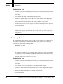
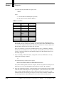
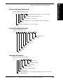
If you use higher conveyor speeds, connect the tachometer directly to a larger diameter driven
roller or use a belt and pulley system to achieve slower tachometer rotation, as shown in
Figure 2–2. Optionally, use a tachometer that generates fewer pulses per revolution. Figure 2–2
displays a pulley arrangement providing a speed reduction of 3 to 1 and a 33% decrease in
tachometer resolution.
FIGURE 2–2.
Pulley Arrangement
Conveyor
Conveyor
Roller
1”Dia.
3”Dia.
Tach
Drive
Pulley
The speed reduction will be proportional to the ratio of the pulley diameters, with the tachometer
connected to the larger diameter pulley. The resolution will decrease in inverse proportion to the
ratio of the diameters.
Mounting Presence Photoeyes
The photoeye positions for your application are specified on your keysheet.
Mounting Photoeye Tree Bracket
The bracket supports the height-detecting photoeyes on one side of the conveyor. A second bracket
supports reflectors for each photoeye on the other side of the conveyor.
Mount the height-detecting photoeyes immediately upstream of the inzone photoeye.
Dimensions of the bracket available from SICK Auto Ident, Inc. are listed in “Photoeye Tree
Bracket” on page C-9.
2-6
CiMAX 75xxA/76xx Scanner Technical Reference Manual
Rev F, February 2002
Site Preparation
Scanner Installation
Connecting CiMAX Scanner & Basic/Standard/Hex Interface Unit
1.
Remove AC power at the circuit breaker.
2.
Connect the AC power cord to line power from the Basic/Standard/Hex Interface Unit.
3.
Connect the 25-pin connector to In/Out PWR and secure it.
4.
Connect the 9-pin female connector to the Host and secure it.
5.
Verify that the Interface Unit power switch is in the Off position.
It is preferable but not necessary to use the SICK Auto Ident, Inc. Basic/Standard/Hex Interface
Unit(s) with the scanner. When you use an Interface Unit, you will obtain all I/O connections,
except Ethernet, at the Interface Unit. Do not attempt to connect directly to the scanner without
contacting SICK Auto Ident, Inc.
Inside the Standard/Hex Interface Unit, use terminal block 1 (TB1) to make low power I/O
connections. Use terminal block 2 (TB2) to make connections to relays. Refer to Chapter 3,
“Controls, Connectors, & Indicators” for connection information.
WARNING! IF YOU ARE USING OPTO-22 MODULES FOR INPUTS AND OUTPUTS,
AC VOLTAGES MAY BE PRESENT IN THE INTERFACE UNIT. YOU SHOULD MAKE
SURE THAT ALL EXTERNAL POWER IS REMOVED FROM THE INTERFACE UNIT’S
INPUTS AND OUTPUTS BEFORE PERFORMING ANY MAINTENANCE. THE ON-OFF
SWITCH ON THE SCANNER DOES NOT CONTROL THESE VOLTAGES.
On-Off Switch
SICK Auto Ident, Inc. recommends that you supply AC power, with a ground wire, to either the
Interface Unit or to user-supplied DC power supplies through an external, fused control switch
meeting all local electrical codes.
Rev F, February 2002
CiMAX 75xxA/76xx Scanner Technical Reference Manual
2-7
2
Installation & Setup
Mount the scanner on a supporting structure next to the conveyor such that it can be exactly
positioned as detailed on your keysheet. The scanner should not be subject to shock or vibration
from the conveyor.
Chapter
2-8
2
Installation & Setup
CiMAX 75xxA/76xx Scanner Technical Reference Manual
Rev F, February 2002
3
Controls, Connectors, & Indicators
CHAPTER 3
This chapter describes the physical layout, controls, connectors and indicators on the CiMAX
75xxA/76xx Scanner, the Basic Interface Unit, Standard Interface Unit, and the Hex Interface Unit.
Scanner
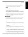
LED Display
There are six status indicators on the rear panel of the CiMAX 75xxA/76xx Scanner, as shown in
Figure 3–1.
FIGURE 3–1.
LED Display
Setup
Presence
yellow
Decode
XMIT/RCV
I/O
green
Rev F, February 2002
PWR/Laser ON
CiMAX 75xxA/76xx Scanner Technical Reference Manual
3-1
Controls, Connectors,
& Indicators
3
Chapter
3
Controls, Connectors, & Indicators
Setup
The SETUP LED indicates that the scanner is in either the Setup or Diagnostics mode rather than in
the normal operating mode. When this LED is On, the CiMAX 75xxA/76xx Scanner is not running
application software.
Presence
The PRESENCE LED shows the status of the scan zone presence detect photoeyes. If the scanner is
configured to use presence, the LED lights when an object is in the scan zone.
Decode
The DECODE LED lights when the scanner is decoding a barcode.
Xmit/Rcv
The XMIT/RCV LED will blink whenever the scanner is sending or receiving data. This includes
messages to and from all sources that are sent via the Host, Setup and Starnode ports. The Ethernet
port is not monitored. This LED helps to verify correct wiring and confirms that the scanner is
receiving communications from any source.
I/O
The I/O LED shows the state of all inputs and outputs (1 through 8) combined. That is, if any of the
inputs or outputs are activated, this LED will be on. To view the status of each input or output, the
user must run the Inputs/Outputs test of the Diagnostics Program. The user may also observe which
relays are active in the Interface Unit.
Pwr/Laser On (green)
This LED indicates that power to the scanner is On. When power is first applied to the scanner, the
scanning motor starts and the on-board computer performs internal diagnostics. After the
diagnostics tests are completed, the laser is turned on and normal operation begins.
Interface Units
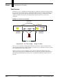
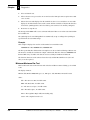
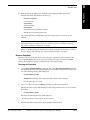
Basic Interface Unit
The Basic Interface Unit allows you to make I/O and relay connections at a more convenient
location than at the scanner itself. The scanner is connected directly to the 15-pin D-type connector
on the Basic Interface Unit, as shown in Figure 3–2. A two-meter cable is provided with the
interface for this purpose.
3-2
CiMAX 75xxA/76xx Scanner Technical Reference Manual
Rev F, February 2002
Interface Units
FIGURE 3–2.
Basic Interface Unit—Block Diagram
DB-9
Starnode
Setup
CiMAX 7600
I/O Power, GND
DB-25
Inputs
Outputs
Power
DB-9
Host
Slave
to Host computer
Basic Interface Unit
DB-15 Connector
RS-232 Serial Comms
TXD, RXD, GND
to relay
Output
Digital Output
AC in
PRES, +12V, GND
to Presence Photoeye
The basic interface provides six screw-down I/O connections, identified by silk-screened labels on
the outside of the case. The DB-15 and screw-down connectors are shown in Figure 3–3.
FIGURE 3–3.
Basic Interface Unit—I/O Panel
SCANNER
CONNECTION
SERIAL
COMM.
OUTPUT
PRESENCE
PHOTOEYE
. . . . . .
DB-15
(also used
for serial com
ground)
GND
RXD
TXD
OUTPUT
+12VDC
PRESENCE
Note: The Basic Interface Unit provides +12VDC ±5% only and is designed for use with the
optionally configured CiMAX 75xxA/76xx Scanner, without Ethernet option.
Rev F, February 2002
CiMAX 75xxA/76xx Scanner Technical Reference Manual
3-3
Controls, Connectors,
& Indicators
3
Chapter
3
Controls, Connectors, & Indicators
I/O Panel Inputs & Outputs
RXD
Terminal connector for RXD signal on an RS-232 communications link with Host computer.
TXD
Terminal connector for TXD signal on an RS-232 communications link with Host computer.
Output
Terminal connection for scanner's solid state Output 1, by default, the NO READ signal.
Presence
Terminal connector for presence signal from an inzone detecting photoeye.
+12VDC
Terminal connector for +12 VDC power for an inzone detecting photoeye (50 mA maximum).
GND
Terminal connector for common grounds for a photoeye and the RS-232 communications link.
Scanner Connection
D-type connector for scanner power, serial communications, inputs and outputs, as shown in
Figure 3–4. The pins assignments of the DB-15 connector are shown in Table 3–1.
FIGURE 3–4.
DB-15 Connector
1
8
15
TABLE 3–1. DB-15
3-4
9
DB-15
Pin Assignments
Pin
Description
1
Not used
2
Host RXD (data from Host)
3
Host TXD (data to Host)
4
Output 1
5
Not Used
6
Presence Input
7
Signal Ground
8
Frame Ground
9
+12 VDC ±5%, 1.2A
10-15
Not Used
CiMAX 75xxA/76xx Scanner Technical Reference Manual
Rev F, February 2002
Interface Units
Connection to a Host
You can connect the Basic Interface Unit to a PC that will act as a Host. This is a three-wire
connection (RXD, TXD, and GND). On a typical 25-pin RS-232 connector on a host computer,
RXD is pin 2, TXD is pin 3, and GND is pin 7.
Standard Interface Unit
FIGURE 3–5.
Standard Interface Unit—Interconnection Block Diagram
Scanner
Terminal or PC
DB-9
CiMAX 7500A
STARNODE
SETUP
Connect to
scanner or at interface unit
DB-25
INPUTS
OUTPUTS
POWER
DB-9
HOST
SLAVE
Standard Interface Unit
J3
DB-9
SET-UP
TB 2 & 6
TB 1
relays
RS-232
Host computer
Presence and height
photoeyes
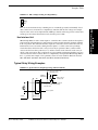
Hex Interface Unit
The Hex Interface Unit is a special box that allows more than one scanner to be used in a tunnel
type application. You can have up to six scanners attached to one interface unit. This allows most of
the common signals to be connected to more than one scanner without additional wiring. It also
allows for a quicker and more reliable installation. Because of the specialized nature of these
applications, this box must be specific to the application.
Rev F, February 2002
CiMAX 75xxA/76xx Scanner Technical Reference Manual
3-5
3
Controls, Connectors,
& Indicators
The Standard Interface Unit allows you to make most CiMAX 75xxA/76xx Scanner connections at
a more convenient location than at the scanner itself, which may be mounted where it is not easily
accessible. The Standard Interface Unit can usually be mounted at the side of the conveyor,
allowing easy access from the floor. Figure 3–5 illustrates how the scanner and the Standard
Interface Unit are interconnected.
Chapter
3
Controls, Connectors, & Indicators
Starnode drop cables can be directly connected to TB7 and TB8. These terminal blocks can be an
extension of any Starnode network branch. All Starnode rules still apply in the layout of Starnode
network (refer to the Starnode Installation & Site Planning Guide). This allows a common connect
for the Starnode drop cables and eliminates the need for individual T-TAP boxes.
Standard Interface Connections
The Standard Interface Unit is connected to the scanner by the cables provided with the system.
The cables connect DC power to the scanner and all of the scanner input, output and
communications signals, to the interface unit. You must connect the network cables directly to the
scanner.
You can connect a PC, running terminal software, to the SETUP port in the SET/STAR connector
on the scanner. However, it may be more convenient to connect it to the SETUP connector inside
the Standard Interface Unit.
The SETUP connector in the Standard Interface Unit does not support the CiMAX 1400 HandHeld terminal.
AC Power
115/230 VAC (auto selected) ±15%, 50/60 Hz, 40 W max power is required by the Standard
Interface Unit. This supplies DC power to itself, to the scanner, and provides AC voltage for relays
controlling AC-operated devices.
The AC Power Cable is fed into the interface through a punch-out hole in the case. The AC line
connections are made at TB7, using the screws labeled NEUT and LINE. The ground wire must be
connected directly to the case, as shown Figure 3–6.
FIGURE 3–6.
AC Power Connection
TB 7
LINE
NEUT
GROUND
CASE
AC LINE IN
Toggle switch S1 on the circuit board is an AC ON/OFF switch. Because the cover of the interface
will normally be closed, AC power should be supplied to the interface through an external, fused
switch.
3-6
CiMAX 75xxA/76xx Scanner Technical Reference Manual
Rev F, February 2002
Interface Units
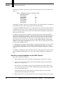
Hex Interface Connections
The Hex Interface Unit requires its own AC power. There is a 4 A 250 VAC, 3AG fuse located in
the fuse compartment above the power switch. To access the fuse, open the fuse compartment with
a small screwdriver.
The Hex Interface Unit provides six setup connectors, one for each scanner.
In some applications, scanner A is acting as a master scanner using its host port to communicate
over a sub-system RS422 multi drop connection to other scanners in the system. This master's setup
port is used to communicate to a host computer using RS-232 on TB1 pins 39 and 40. If Switch 1
(S1) is in the normal position, scanner A setup port is also connected to a RS-232 to RS-422
converter. The RS-422 host connection will be made on TB9 pins 1 - 4.
Switch 2 is a dipswitch that may be used to connect a number of scanners setup port receive data
lines together. This may be used when data from the Programmable Interface Controller must be
sent to all of the scanners. SICK Auto Ident, Inc. cable (A1-63397-1) will be connected between
Programmable Interface Controller J1 and Hex Interface Box J18. Make sure that the cable end
with pin 8 is connected to the Programmable Interface Controller. Switch 2 positions are as follows:
•
If all scanners are to receive the same data on the Setup Port, S2 should be set (11111xxx),
where:
–
1=On
–
0=Off
–
x= don’t care
•
Position 5—F (BCDEFxxx) Position 5 must be set to On to connect data to any other scanners.
Scanner F gets data directly from J18.
•
Scanner A requires that S1 be in the setup position to receive data.
When the CiMAX 75xxA/76xx Scanner is connected to the Hex Interface Unit, ensure the correct
switch is On for that scanner. Those scanners must use the SETUP port to receive data from the
Programmable Interface Controller. If you wish to use this port for setup or diagnostics, set the
applicable switch to Off temporarily, during testing.
Rev F, February 2002
CiMAX 75xxA/76xx Scanner Technical Reference Manual
3-7
3
Controls, Connectors,
& Indicators
If you position the Hex Interface Unit with the scanner cables exiting on your left side, scanner A is
the cable closest to the slide Starnode door. The scanners are labeled A through F, with scanner F
located closest to the corner of the box.
Chapter
3
Controls, Connectors, & Indicators
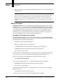
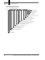
FIGURE 3–7.
S1 & S2 Connection Diagram
Normal
S1
(A) TXD
J3-8
(A) RXD
RS-232/422
Converter
J3-7
Setup
S2
J6
J9
J12
J15
J18
Scanner (B) RXD
Scanner (C) RXD
Scanner (D) RXD
Scanner (E) RXD
Scanner (F) RXD
1
2
3
4
5
6
7
8
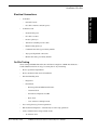
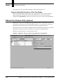
Another use of these switches is when you wish to update the operating system of more than one
scanner at the same time. If you wish to upgrade the OS, communication to a scanner must be made
to that scanner’s setup port through one of the six connectors in the Hex Interface Unit. Each
connector is used for each individual scanner. For example, if you have two CiMAX 75xxA
Scanners or two CiMAX 76xx Scanners attached to positions C and D, connect the computer to J9
or J12. Set S1 to normal and S2 to 01100000 (0=off, 1=on).
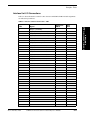
Control Input Connections
Interface Unit Inputs
All standard solid state control input connections to the Interface Unit(s) are available at terminal
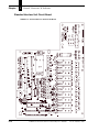
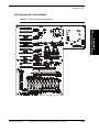
block TB1, as shown in Figure 3–10, “Standard Interface Unit Circuit Board” on page 3-12, and
Figure 3–11, “Hex Interface Unit Circuit Board” on page 3-13.
Connector assignments are listed in Table 3–2, “Interface Unit I/O Connections—TB1,” on
page 3-17.
Eight low-voltage DC solid state control inputs are provided and are, by default, assigned to accept
inzone and outzone presence, tachometer and five height sensor signals, as specified in Table 3–2,
“Interface Unit I/O Connections—TB1,” on page 3-17. The assignments are shown in parentheses
in the table. A custom C program or the Setup parameters may be used to override the default
assignments.
3-8
CiMAX 75xxA/76xx Scanner Technical Reference Manual
Rev F, February 2002
Interface Units
An optional DC-to-DC converter provides isolated DC power for photoeyes and a tachometer.
Isolated +12 and +5 volts DC and ground terminals are available on terminal block TB5. Using
these voltages and the opto-isolated inputs will provide total isolation.
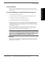
Programmable Interface Controller Inputs
Standard inputs 4-8 are used for height sensing. When used, the least significant height is
connected to input 4 of the Interface Unit(s).
Optional Input Relay Modules
As many as eight optional solid-state input relay modules can be used to accommodate AC input
signals. Refer to “Relays in the Interface Units” on page 3-14 for more information.
Control Output Connections
Eight solid-state open-collector control outputs are available at terminal block TB1 on the main
printed circuit board, to operate relays, alarms, diverters, etc. Connector assignments are listed in
Table 3–2, “Interface Unit I/O Connections—TB1,” on page 3-17. Refer to Figure 3–8, “Typical
Solid State Output Circuit” on page 3-10.
By default, three of the outputs are assigned to output NO READ, MATCH and NO MATCH
signals, as specified Table 3–2, “Interface Unit I/O Connections—TB1,” on page 3-17. The
assignments are shown in parentheses in the table. A custom C program or the Setup parameters
may be used to override the default assignments.
As many as seven optional solid-state output relay modules, and one form C (SPDT) electromechanical relay, are available to switch AC voltages. Refer to “Relays in the Interface Units” on
page 3-14 for more information.
Special Inputs & Outputs
Laser Control
A digital low or switch closure to ground on this input will turn the laser On or Off, depending upon
how a jumper inside the scanner was configured at the factory. The default position of jumper JH2
is between pins 1 and 2. This is referred to as a normal laser control. With no connection, or logical
high on the input laser control, the laser will be On. A ground or logical low on laser control input
causes the laser to turn Off. Moving the jumper to position 2 to 3 causes this function to be reversed
and referred to as an inverted laser control.
Rev F, February 2002
CiMAX 75xxA/76xx Scanner Technical Reference Manual
3-9
3
Controls, Connectors,
& Indicators
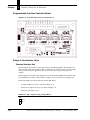
Up to seven additional low-voltage DC inputs are available at terminal block J2 on an optional
Programmable Interface Controller, as shown in Figure 3–12, “Programmable Interface Controller
Board” on page 3-14. The inzone photoeye is connected to input 8 of the Programmable Interface
Controller. The extra height photoeyes are connected to inputs 1 - 7 of the Programmable Interface
Controller, with lowest input connected to input 1 of the Programmable Interface Controller. On the
leading edge of inzone, the peak-detected state of the 7 inputs, the highest number of photoeyes
blocked since the last inzone, are sent serially to the scanner. They permit additional height sensing,
for better resolution of height and corresponding better accuracy for x, y positioning to allow
smaller gaps between boxes.
Chapter
3
Controls, Connectors, & Indicators
Beeper
The Beeper output is an open collector output providing an audio tone to signal the operator each
time that the scanner has read a label.
By default, Output 4 is used to drive the beeper. Jumper JH6 in the Standard Interface Unit is used
to connect Output 4 to the beeper. For beeper operation, position JH6 across pins 2 and 3.
Refer to Figure 3–10, “Standard Interface Unit Circuit Board” on page 3-12 which shows the
location of JH6.
To use Output 4 as a general purpose output:
1.
Place the JH6 jumper across pins 1 and 2.
2.
Set parameter 003 IOMODE to +16 to disable the beeper. Refer to the Scanner Parameters
Reference Guide for more information.
Communications Inputs & Outputs
Host and SETUP port connections are available on terminal block TB1. Terminal assignments for
these ports are shown in Table 3–2, “Interface Unit I/O Connections—TB1,” on page 3-17.
DC Power Outputs
Terminal block TB1 also provides several non-isolated low voltage DC outputs for powering
external sensors, as well as associated ground connections. The ratings of the DC outputs are
shown in Table 3–2, “Interface Unit I/O Connections—TB1,” on page 3-17.
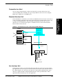
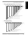
Solid State Input & Output Circuits
Figure 3–8 and Figure 3–9 show typical Solid State Input and Output Circuits.
FIGURE 3–8.
3-10
Typical Solid State Output Circuit
CiMAX 75xxA/76xx Scanner Technical Reference Manual
Rev F, February 2002
Interface Units
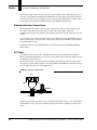
FIGURE 3–9.
Typical Solid State Input Circuit
+12 VDC
10K Ohms
Scanner input
active low when input < 1.0 volts
Rev F, February 2002
3
0.1 µf
CiMAX 75xxA/76xx Scanner Technical Reference Manual
Controls, Connectors,
& Indicators
Maximum input voltage
30 VDC, 27 VDC continuous
ULN2003
3-11
Chapter
3
Controls, Connectors, & Indicators
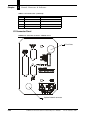
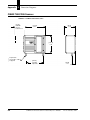
Standard Interface Unit Circuit Board
FIGURE 3–10.
3-12
Standard Interface Unit Circuit Board
CiMAX 75xxA/76xx Scanner Technical Reference Manual
Rev F, February 2002
Interface Units
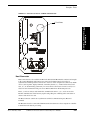
Hex Interface Unit Circuit Board
FIGURE 3–11.
Hex Interface Unit Circuit Board
Controls, Connectors,
& Indicators
3
Rev F, February 2002
CiMAX 75xxA/76xx Scanner Technical Reference Manual
3-13
Chapter
3
Controls, Connectors, & Indicators
Programmable Interface Controller Board
FIGURE 3–12.
Programmable Interface Controller Board
Relays in the Interface Units
Standard Interface Unit
Optional output relay modules can be plugged into locations K1 through K7. Standard Opto-22
style solid state output relay modules with several different AC and DC voltage and power ratings
can be provided to fit your application. You can use these relays to operate divert gates, for
example.
Optional input relay modules can be plugged in to locations K1 through K5. Relay modules with
several different AC and DC voltage and power ratings can be provided to fit your application.
Position the jumpers associated with relay modules JH1-JH5 to:
•
IN when an input relay is used, as shown in Figure 3–13
•
OUT when an output relay is used, as shown in Figure 3–14
•
OUT when no module is used
FIGURE 3–13.
JH1-5 Jumper Setting for Input Relays
JHX
OUT
____
IN
3-14
CiMAX 75xxA/76xx Scanner Technical Reference Manual
Rev F, February 2002
Interface Units
FIGURE 3–14.
JH1-5 Jumper Setting for Output Relays
JHX
OUT
____
IN
Hex Interface Unit
JH18 through JH22 are used to isolate inputs 4 - 8 from the three scanners attached to the top three
positions (D-F) of the Hex Interface Unit. Normal operation requires that these shunts be installed
in the 1-2 position. This will insure that these inputs are connected to all six scanners the same way.
If this interface box is used side scanning, then the inputs 4 - 8 will be connected to proximity
sensors that detect which side of the conveyor a box may be positioned. Three scanners will be
connected to the lower three positions (A - C) and the scanners on the other side of the conveyor
will be connected to the top three positions (D - F). The proximity information should be in reverse
order from the lower three scanners. This is accomplished by moving shunts JH18 through JH22 to
the 2 - 3 position. For example, if five proximity sensors are used, install 22 AWG wire between
TB1 AND TB11 (IN4-IN8A, IN5-IN7A, IN6-IN6A, IN7-IN5A, IN8-IN4A).
Typical Relay Wiring Examples
FIGURE 3–15.
Open Collector Output Operating an External Relay
+V to match coil requirements
(supplied by user)
1N4003 or
similar diode
TB1
Output 1
Relay contacts
to switch load
NOTE: A separate supply is required
for relay coils with voltage ratings
other than 12V.
To user ground
GND
Scanner
Rev F, February 2002
Interface Unit
CiMAX 75xxA/76xx Scanner Technical Reference Manual
3-15
3
Controls, Connectors,
& Indicators
K8 is an electro-mechanical relay containing one set of normally open (NO) and normally closed
(NC) contacts. You can use K8 to accomplish logic functions with AC line voltage. For example,
relays in series can be used to implement the AND logic function. This relay provides contacts that
remain open, and contacts that remain closed, when the power is OFF.
Chapter
3
Controls, Connectors, & Indicators
FIGURE 3–16.
Solid State Output Relay
+12 VDC
TB2
Line
4.7K
Solid state
Output relay
module
(OAC12)
K1
Hot
K1 IN
Divert Gate
Power
K1 OUT
Load Divert
Gate
Neutral
Interface Unit
Scanner
FIGURE 3–17.
K-8 Electro-Mechanical Relay Connection
TB2
TB1
+12V
+24 VDC
K8
to
Scanner
K8-NO
24 VDC ground
LOAD
K8-COM
screw
15
K8-NC
C-NO: Normally open contact
C-NC: Normally closed contact
Interface Unit
FIGURE 3–18.
Solid State Input Relay Module
TB1
TB2
Divert
Control
Relay
K1
to
Scanner
Input
K1 IN
Input
Divert
Gate
Solid state
input relay
module
(IAC15)
Divert
Gate
Power
K1 OUT
Interface Unit
3-16
CiMAX 75xxA/76xx Scanner Technical Reference Manual
Rev F, February 2002
Interface Units
Interface Unit I/O Connections
Table 3–2 shows the Interface Unit I/O connections at Terminal Block TB1. Default assignments
are indicated in parentheses.
Unit I/O Connections—TB1
TB1
Signal
In/Out Pwr
DB-25
1
Output 1 (NO READ)
9
2
Input 1 (INZONE PRESENCE)
1
3
Output 2 (MATCH)
10
4
Input 2 (OUTZONE PRESENCE)
2
5
Output 3 (NO MATCH)
11
6
Input 3 (TACHOMETER)
3
7
Output 4 (BEEPER)
12
8
Input 4 (HEIGHT SENSOR 1)
4
9
Output 5
13
10
Input 5 (HEIGHT SENSOR 2)
5
11
Output 6
14
12
Input 6 (HEIGHT SENSOR 3)
6
13
Output 7
15
14
Input 7 (HEIGHT SENSOR 4)
7
15
Output 8
16
16
Input 8 (HEIGHT SENSOR 5)
8
18
Beep
12
19
+12 VDC
19
Host
DB-9
3
Controls, Connectors,
& Indicators
TABLE 3–2. Interface
17
20
Ground
21
+5 VDC
22
Ground
23
Ground
24
+12 VDC
24
5
20
25
26
Host TXD
3
27
Host RXD
2
Host T422+
1
28
29
30
31
32
33
34
Rev F, February 2002
CiMAX 75xxA/76xx Scanner Technical Reference Manual
3-17
Chapter
3
Controls, Connectors, & Indicators
TABLE 3–2. Interface
Unit I/O Connections—TB1 (continued)
In/Out Pwr
DB-25
Host
DB-9
TB1
Signal
35
Host T422-
6
36
Host R422+
7
37
Host R422-
9
39
Setup TXD
8
40
Setup RXD
4
41
+5 VDC
25
42
Laser control
17
46
Ground
21
47
Ground
22
48
Ground
23
Frame Ground
18
38
43
44
45
49
50
Expansion Board Input Connections
Table 3–3 shows the Expansion Board Input connection at Terminal Block J2.
TABLE 3–3. Expansion
3-18
Board Input Connections
J2 Marked
Assignment
1 (INZ)
Height Input 1
2 (ANG)
Height Input 2
3 (TACH)
Height Input 3
4 (HT1)
Height Input 4
5 (HT2)
Height Input 5
6 (HT3)
Height Input 6
7 (HT4)
Height Input 7
8 (HT5)
Inzone Presence (connect to TB1-2)
9 +5V
+5V
10 GND
GND
11 CTSOUT
CTSOUT (RS-232)
12 CTSIN
CTSIN (TTL)
CiMAX 75xxA/76xx Scanner Technical Reference Manual
Rev F, February 2002
Interface Units
Photoeye & Tachometer Connections
Note: Connections shown here are for SICK Auto Ident, Inc. parts only.
Use TB3, TB4 and TB5 instead of TB1 for complete opto-isolation. Refer to Table 3–2, “Interface
Unit I/O Connections—TB1,” on page 3-17 for TB1 assignments.
3
Photoeye & Tachometer Connections
Controls, Connectors,
& Indicators
FIGURE 3–19.
Brown
+12V
24
Gnd
Inzone photoeye
935-0018-1
Black
23
Input 1
Blue
White
(not used)
2
Gnd
20
Brown
+12V
24
Gnd
Outzone photoeye
935-0018-1
Black
Blue
White
(not used)
23
Input 2
4
Gnd
20
Brown
+12V
49
Height sensor
1 photoeye
Gnd
Black
Blue
White
(not used)
48
Input 4
8
Gnd
20
Gray/White
Tachometer
950-0003-1
Brown/White
Green/White
Input 3
6
+5V
45
Gnd
47
Interface Unit
Connectors on Scanner I/O Connector Panel
Refer to Table 3–2, Table 3–3, and Table 3–4 for connector and signal specification for the Scanner
I/O connector.
TABLE 3–4. I/O
Connections
Pin
Host
Set/Star
1
Host T422+
LAN+ (blue wire)
2
Host RXD
TERM DETECT
3
Host TXD
LAN- (white wire)
4
Host DTR
Ground
5
Ground
Frame Ground (cable shield)
Rev F, February 2002
CiMAX 75xxA/76xx Scanner Technical Reference Manual
3-19
Chapter
3
Controls, Connectors, & Indicators
TABLE 3–4. I/O
Pin
Connections (continued)
Host
Set/Star
6
Host T422-
Ground
7
Host R422+
TERM RXD
8
Host CTS
TERM TXD
9
Host R422-
+5 VDC, 500 mA max
I/O Connector Panel
FIGURE 3–20.
I/O Connector Panel—CiMAX 75xxA
Test Points
Optional Network connector
3-20
CiMAX 75xxA/76xx Scanner Technical Reference Manual
Rev F, February 2002
Interface Units
FIGURE 3–21.
I/O Connector Panel—CiMAX 7600/7650/7655
Test Points
Controls, Connectors,
& Indicators
3
Host Connector
Host Connections are also available on TB1 in the Standard and Hex Interface Unit and are brought
to the scanner through the I/O Connections connector. The Host Connector provides an
asynchronous serial I/O port that can be used to connect to a host computer or to other serial, ASCII
devices (such as printer, display terminals, external keyboards, etc.). Control of data flow, baud
rates, etc., are determined by parameters you can set. Refer to the Scanner Parameters Reference
Guide for more information. This port can use RS-232, RS-422 or full modem protocols.
Pins 2, 3, and 5 are always used for RS-232 communication. Pins 1, 5, 6, 7, and 9 are used for
RS-422 communication. Your host may require using other pins or making other connections in
order to send and receive data.
The Host Connector contains two asynchronous serial I/O communication ports, Host and
Terminal.
The Host Port is used to connect the CiMAX 75xxA/76xx Scanner to a host computer or controller
to transfer barcode data for processing.
Rev F, February 2002
CiMAX 75xxA/76xx Scanner Technical Reference Manual
3-21
Chapter
3
Controls, Connectors, & Indicators
The SETUP Port is used to connect the scanner to another scanner or to a printer, display terminal
or computer.
Control of data flow, baud rates, communications protocols, etc., from both ports can be set by
means of parameters and software jumpers (parameters 100-199, 200-299, and 495). Refer to the
Scanner Parameters Reference Guide for more information.
The Host port can be programmed to use either RS-232 or RS-422 conventions, or both. The
SETUP port uses only RS-232.
Starnode Setup Connector
The Starnode Connector allows the CiMAX 75xxA/76xx Scanner to be connected to an EIA-485
Starnode local area network (LAN). This network connection is not implemented in the Interface
Unit. You must attach your network cable directly to the connector on the rear panel of the scanner.
Refer to Table 3–4, “I/O Connections,” on page 3-19.
Setup Port Functionality on Starnode Connector
The SETUP connector is provided as an input port for a local terminal. You can connect a CiMAX
1400 hand-held terminal, an ASCII terminal or a PC running a terminal emulation program. This
port uses RS-232 conventions and runs at 9600 baud. Refer to Table 3–4, “I/O Connections,” on
page 3-19.
Setup connections are also available on TB1 in the Standard and Hex Interface Units and are
connected to the scanner through the I/O Connections connector.
A terminal can be used to display and change parameters values and run diagnostic tests. These
functions are described in other chapters in this manual. Most terminals only require connection to
pins 6, 7 and 8.
The CiMAX 1400 terminal also uses pins 2 and 9. A cable with the necessary connections is
provided with the terminal. Some terminals may require connecting to or jumpering other pins.
Optional Network Connectors—CiMAX 75xxA only
A BNC coaxial connector (standard) for 10 Base 2 thinnet or an RJ-45 connector for 10 base T
twisted pair is provided with an Ethernet option. A 4-pin SDS or 5-pin DeviceNet connector is
provided with a CAN option. No network connections are available in the Standard or Hex
Interface Units. If your scanner has the network option installed, you must attach your network
cable directly to the connector on the I/O Connector panel of the scanner.
Electrical Test Points
Six electrical test points, mounted on the printed circuit board, can be accessed by removing the
round plug located in the upper right corner of the scanner I/O panel.
Test point information is included in this manual for completeness. The test points are for use by
factory personnel during setup and adjustment. The test point signals are:
MOD1—Laser Modulation
An analog input signal that can be used to compensate for the lower laser power at the beginning
and end of each scan line.
3-22
CiMAX 75xxA/76xx Scanner Technical Reference Manual
Rev F, February 2002
Interface Units
LSR1—Laser Current
A voltage which, when divided by the laser diode resistance, provides an estimate of the diode
current.
ANA1—Analog Signal
The analog voltage from the detector before it is digitized. This signal is used to adjust the
polarizing filter in the scanner.
Digitized bar code signals used to adjust the phase and mechanical position of the polygon mirror.
SOS1—Start Of Scan
A sync signal used when viewing waveforms on an oscilloscope.
GND1—Ground
A ground connection for equipment connected to the test points.
Rev F, February 2002
CiMAX 75xxA/76xx Scanner Technical Reference Manual
3-23
Controls, Connectors,
& Indicators
3
BAR1—Barcode Signal
Chapter
3-24
3
Controls, Connectors, & Indicators
CiMAX 75xxA/76xx Scanner Technical Reference Manual
Rev F, February 2002
4
Introduction to Scanning
CHAPTER 4
This chapter describes the basics of laser barcode scanning, the operation of single line scanners
and scan tunnel applications.
4
The laser diode used in a barcode scanner generates a low-power beam of (670 nm) red laser light.
Rotating flat mirrors reflect this beam such that it sweeps rapidly across the scanning zone. The
light you see looks like a long, thin red line.
Barcode labels scanned by the laser beam reflect varying amounts of the laser's light back to the
scanner where the rotating mirrors direct the reflected light to the scanner's receiver optics.
A photo diode in the receiver generates an electrical signal that varies in proportion to the intensity
of light reflected by the barcode as it is scanned. Other circuits amplify the signal.
The black-colored bars of a barcode reflect much less light than the light-colored spaces between
the bars. Light of lower intensity is reflected from a bar than from a space. As the beam sweeps
over the barcode, a pattern of analog signal levels is created in the scanner, which duplicates the
pattern of bars and spaces. The timing relationship between this analog waveform and the widths of
the bars and spaces depends on the rotation speed of the mirrors and the distance from the scanner
to the barcode.
The receiver circuitry converts the analog waveform to a digital waveform consisting of a series of
uniformly high and low signal levels. This digital waveform is passed, along with a start-of-scan
signal, to the scanner's decode circuitry.
Reading Barcodes
Successful barcode reading requires printing labels with precise, crisp, clearly defined highcontrast bars and spaces.
The X Dimension
The scanner analyzes the digital waveform and determines the width of the narrowest bars and
spaces. This width is referred to as the X dimension.
On the printed barcode, the X dimension is the width of the smallest space or bar, traditionally
measured in thousandths of an inch, or mils. Figure 4–1 shows the X dimension of bars and spaces
in a typical barcode.
Rev F, February 2002
CiMAX 75xxA/76xx Scanner Technical Reference Manual
4-1
Introduction to
Scanning
Introduction
Chapter
4
Introduction to Scanning
FIGURE 4–1.
X-Dimension
The size of the narrowest bar must
equal the size of the narrowest space
X Dimension
X Dimension
In the scanner, the widths of all other bars and spaces are measured and expressed as multiples of
X. For example, symbologies such as Code 39 and Interleaved or Straight 2-of-5 use only two
widths, X and 2X (wide and narrow). Other symbologies, such as Code 128 and UPC/EAN, use up
to four element widths, with bars and spaces ranging from X to 4X.
Measuring Barcodes
The X dimension of a barcode is traditionally measured in thousands of an inch (mils), using an
optical comparator. This is available from SICK Auto Ident, Inc. or optical suppliers. Ideally, the
width of the narrowest space should equal the width of the narrowest bar.
Your scanner has been set up to read the minimum X dimension specified on the Keysheet. For best
scanner performance, the actual X dimension of your barcodes should be no smaller than the
specified dimension. If your barcodes have too narrow an X dimension, your scanner may not be
able to read codes over its entire reading range.
Quiet Zone
There must be a Quiet Zone of at least ten times the X dimension on both ends of the barcode. The
color and surface of the label material in the Quiet Zone and in the spaces must be the same.
After the scanner has determined a barcode's X dimension, it interprets all spaces of 10X or greater
as quiet zones, and all bars and spaces between the quiet zones as barcode data. Figure 4–2
illustrates spaces, bars and quiet zones. The sizes of the quiet zones have been exaggerated for
clarity.
4-2
CiMAX 75xxA/76xx Scanner Technical Reference Manual
Rev F, February 2002
Reading Barcodes
Barcode—Quiet Zone
4
Quiet Zones for Stitching
If your scanner is equipped with SICK Auto Ident, Inc. CIX technology, your barcodes must have a
10X minimum quiet zone on all four sides of the barcode. This will allow for stitching, which is the
connecting of segments of barcode. Figure 4–3 illustrates the ideal barcode label for scanning
operations that include stitching. The sizes of all four quiet zones have been exaggerated for clarity.
FIGURE 4–3.
Barcode—Stitching
Optical Considerations
After barcode printing quality, the next most important factor in scanner operation is maintaining
the correct distance between the scanner and the barcodes being scanned. The barcodes must pass
through the effective reading area, illustrated in Figure 4–4.
Rev F, February 2002
CiMAX 75xxA/76xx Scanner Technical Reference Manual
4-3
Introduction to
Scanning
FIGURE 4–2.
Chapter
4
Introduction to Scanning
FIGURE 4–4.
Effective Reading Area
Effective
reading
area
Height of
scan (HOS)
Scan angle
Scanner
Depth of field
(DOF)
Furthest distance
at which labels can
be read
Optical throw
(OT)
Closest distance
at which labels can
be read
Your Keysheet specifies the maximum and minimum distances allowed between barcode labels and
the scanner. You must install the scanner such that the labels will pass within these limits.
Depth of Field
The depth of field is the difference between the maximum and minimum distances at which
barcodes can be read.
In general, depth of field will be equal to about 50 percent of the reading range for barcodes with
small X dimensions, and up to about 70 percent for barcodes with large X dimensions.
Optical Throw
The optical throw is the distance from the scanner's window or, on some scanners, from a datum
line on the side of the scanner, to the beginning of the depth of field. Optical throw is the distance
from the scanner to the closest point at which a barcode can be read.
Reading Range
The reading range is the maximum distance from the scanner at which barcodes can be read. The
reading range is equal to the sum of the optical throw and the depth of field.
Height of Scan
The height of scan is the length of the laser scan line at the minimum reading distance. SICK Auto
Ident, Inc. scanners support a constant height of scan, as listed on your Keysheet and illustrated in
Figure 4–4.
Scan Angle
The scan angle is the maximum angle generated by the laser beam during scanning, as illustrated in
Figure 4–4.
4-4
CiMAX 75xxA/76xx Scanner Technical Reference Manual
Rev F, February 2002
Reading Barcodes
Barcode Orientation
Barcodes can pass a scanner in one of two possible orientations:
•
Ladder
•
Picket Fence
Ladder
In Ladder orientation, the bars and spaces are parallel to the direction of travel of a box on a
conveyor, making the bars in the code resemble the rungs of a ladder as shown in Figure 4–5. When
the scanner is installed such that the laser beam scans in the vertical direction, it can read ladderoriented barcodes.
FIGURE 4–5.
Ladder Orientation
4
Introduction to
Scanning
Scanning line
Ladder Orientation
Figure 4–6 displays a conveyor that carries boxes containing ladder-oriented barcodes that exhibit
tilt, pitch and skew. The first three boxes from left to right are incorrectly positioned for optimal
barcode reading.
It is rare when a barcode is aligned exactly perpendicular to the scanning beam. Accordingly, three
barcode orientations must be handled, all of which can reduce the quality of barcode reading.
Rev F, February 2002
CiMAX 75xxA/76xx Scanner Technical Reference Manual
4-5
Chapter
4
Introduction to Scanning
FIGURE 4–6.
Ladder Orientation Displaying Tilt, Pitch, Skew, and Best
Tilt
Pitch
Skew
Best
Scanner
Picket Fence
In picket fence orientation, the bars and spaces are perpendicular to the direction of travel of a box
on a conveyor, making the bars in the code resemble the pickets of a fence as shown in Figure 4–7.
When the scanner is installed such that the laser beam scans in the horizontal direction, it can read
picket fence-oriented barcodes.
FIGURE 4–7.
Picket Fence Orientation
Scanning line
Picket Fence Orientation
Figure 4–8 displays a conveyor that carries boxes containing picket fence-oriented barcodes that
exhibit tilt, pitch and skew. The first three boxes from left to right are incorrectly positioned for
optimal barcode reading.
It is rare when a barcode is aligned exactly perpendicular to the scanning beam. Accordingly, three
barcode orientations must be handled, all of which can reduce the quality of barcode reading.
4-6
CiMAX 75xxA/76xx Scanner Technical Reference Manual
Rev F, February 2002
Reading Barcodes
FIGURE 4–8.
Picket Fence Orientation Displaying Tilt, Skew, Pitch, and Best
Tilt
Skew
Pitch
Best
Tilt
Tilt is the rotation of a barcode about an axis that passes through the barcode perpendicular to its
plane. As shown in Figure 4–9, the barcode cannot be read by a single laser scan when the tilt
becomes so great that the beam does not cut across all of the bars and spaces during one sweep.
FIGURE 4–9.
Varying Degrees of Tilt
Scanning line
If your scanner is equipped with optional CIX technology, then greater tilt can be handled. As long
as the scanner beam passes through at least one complete character in the barcode on each scan, the
scanner can stitch the pieces of code obtained from multiple scans together until a complete decode
is obtained.
If your scanner is not equipped with CIX technology, then a successful read and decode of a
barcode can only be obtained if the scanning beam crosses every bar and space in the barcode in a
single sweep. If even one bar or space is missed, a No Read will result. Figure 4–9 shows the
barcode on that the right is tilted so far that CIX technology is required to read it.
Rev F, February 2002
CiMAX 75xxA/76xx Scanner Technical Reference Manual
4-7
Introduction to
Scanning
4
Scanner
Chapter
4
Introduction to Scanning
Pitch
Pitch is the rotation of the barcode about an axis parallel to and in the plane of the bars and spaces,
as shown in Figure 4–10. The greater the barcode pitch, the thinner the bars and spaces will appear
to the scanner. In addition, the length of the barcode will appear to grow shorter. At some angle, the
scanner will no longer be able to measure the widths of the bars and spaces in the code.
FIGURE 4–10.
Pitch Orientation
Bar code pitch increases
as box tips away from scanner
Scanning beam
Scanner
Skew
Skew is the rotation of the barcode about an axis perpendicular to the bars and spaces and in the
plane of the code. The greater the skew, the less height the barcode appears to have to the scanner.
At some angle, the height will become too small for the scanner to read.
Number of Scans per Barcode
Regardless of which orientation barcodes are in when they pass the scanner, the scanning
application should be constructed such that the scanner makes some minimum number of
successful scans while the barcode is within the reading area. For example, the application might be
constructed such that a barcode will be scanned not less than five times before it passes out of the
scanning zone.
Ladder and Picket Fence codes have different number-of-scans equations, as shown in Figure 4–11
and Figure 4–12.
FIGURE 4–11.
Ladder Equation
Bar Height
Scans/Barcode = Scan Rate X
----------------------Conveyor Speed
FIGURE 4–12.
Picket Fence Equation
Height of Scan - Length of Code
Scans/Barcode = Scan Rate X
------------------------------------------Conveyor Speed
4-8
CiMAX 75xxA/76xx Scanner Technical Reference Manual
Rev F, February 2002
Reading Barcodes
These equations assume that the barcode is not tilted and that the units of measurement are
consistent.
Presence Detection
Presence Detection is the method normally used to tell the scanner when to read a barcode. This is
usually implemented by a using a photoeye to sense the light returned by a reflector mounted on the
opposite side of the conveyor. When an object on the conveyor blocks the light, a signal from the
photoeye instructs the scanner to begin reading. When the object no longer blocks the light, a signal
from the photoeye instructs the scanner to stop reading and to transmit the barcode data. Ideally, the
presence signal will be on from just before the barcode passes in front of the scanner beam until just
after it passes. If no barcode is read during the presence cycle, a No Read message is usually sent to
the host computer or controller.
Presence Detection can sometimes be implemented with a single photoeye. It is often possible
when the scanner is reading ladder-oriented codes with a vertical scanner beam and sometimes
possible when reading picket fence oriented codes with a horizontal scanner beam.
When reading picket fence codes, two photoeyes in a zone presence configuration should be used if
the usable scan zone (the scanner's height of scan) is longer than the boxes to be scanned. In this
configuration, a photoeye is typically located at each end of the scan zone. The presence cycle
begins when a box first blocks the inzone photoeye and ends when the box no longer blocks the
outzone photoeye.
This configuration makes the scan zone longer than is possible using a single photoeye, and it takes
advantage of the increased reading area made possible by the horizontal scanning line. When using
zone presence detection, it is imperative that only one box be in the scanning zone at a time so that
a barcode will always be associated with its corresponding box.
Single Presence
In the Single Presence configuration, one photoeye detects each box and signals the scanner to
begin reading. The scanner is normally set to transmit the decoded barcode data, if any, when the
photoeye signals that the box is no longer detectable. Figure 4–13 shows the scanner mounted such
that the laser beam scans vertically, and the barcodes have a ladder orientation.
FIGURE 4–13.
Single Presence Detection
Top View
Reflector
Conveyor
box
Direction
of travel
Photoeye
Scanner
Rev F, February 2002
CiMAX 75xxA/76xx Scanner Technical Reference Manual
4-9
Introduction to
Scanning
4
Chapter
4
Introduction to Scanning
Zone Presence
In the Zone Presence configuration, an inzone photoeye signals the scanner that a box has entered
the scan zone and an outzone photoeye signals that the box has left. The scanner is normally set to
transmit its decoded barcode data after the box has left the zone. Figure 4–14 shows the scanner
mounted such that the laser beam scans horizontally and the barcodes have a picket fence
orientation.
FIGURE 4–14.
Zone Presence Detection
Top View
Reflectors
Conveyor
box 2
Usable
scan
box 1
Direction
of travel
Out-zone
photoeye
In-zone
photoeye
Scanner
Scan zone
Gap between
Scan zone
Height of usable
Zone Presence is useful in scanning applications where picket fence codes are affixed to boxes
whose length is less than the scanner's height of scan. Zone Presence allows the scanner to read the
barcode throughout the entire height of scan.
Figure 4–15 shows a scanner attempting to read a barcode from the time that the box is first
detected by the inzone photoeye until the time that it is no longer detected by the outzone photoeye.
The timing diagram illustrates how zone presence extends the time that the scanner has to read
barcodes.
4-10
CiMAX 75xxA/76xx Scanner Technical Reference Manual
Rev F, February 2002
Reading Barcodes
FIGURE 4–15.
Zone Presence and Extended Read Time
Side View
Direction of travel
Box first detected by
inzone photoeye
t=1
Box no longer detected
by inzone photoeye
t=2
4
Box first detected by
outzone photoeye
Box no longer detected
by outzone photoeye
Photoeye signals
Introduction to
Scanning
t=3
t=4
Inzone
Outzone
1
2
3
4
Presence
Gap Tracking
Gap Tracking, also called box or package tracking, is a technique that allows a scanner to keep
track of the locations of up to eight boxes while they are in the scan zone. It allows the scanner to
correctly associate each barcode with its box, even if a scan line sweeps across more than one box
and barcode. Gap tracking is required whenever there may be more than one box at a time in the
scan zone.
In Figure 4–16, the gap is larger than the scan zone. Box 1 will leave the scan zone before box 2
enters the zone. In this situation, gap tracking is not needed.
Rev F, February 2002
CiMAX 75xxA/76xx Scanner Technical Reference Manual
4-11
Chapter
4
Introduction to Scanning
FIGURE 4–16.
Gap Tracking—Not Required
Scanning beams
Inzone
Outzone
Scan Zone
Conveyor
Bar Code
Label
Bar Code
Label
Direction
of Travel
Top of box 2
Top of box 1
Gap (larger than scan zone)
Scanning beams
In Figure 4–17, gap tracking is required because two boxes and their barcode labels are in the scan
zone at the same time. If gap tracking is not implemented, the scanner may assign the barcode to
the wrong box.
FIGURE 4–17.
Gap Tracking—Required
Scanning Beams
Scanning
beams
Inzone
Outzone
Bar Code
Label
Bar Code
Label
Direction
Direction
of Travel
of
Travel
box
box 22
Conveyor
Conveyor
box
box11
Gap
Gap
Scanning Beams
Scanning beams
The minimum expected gap between boxes has been specified by the requirements of your
application. Refer to your Keysheet.
To avoid problems created by insufficient gaps between barcodes or boxes, you may have to install
additional sensors and devices. Refer to your Keysheet to determine if your application requires
this additional equipment.
For more information about gap tracking, refer to parameters 700-725 in the Scanner Parameters
Reference Guide and to “Gap Tracking Diagnostics” on page 8-22.
4-12
CiMAX 75xxA/76xx Scanner Technical Reference Manual
Rev F, February 2002
Reading Barcodes
Additional Inputs
The scanning beams cover an area that extends along the direction of travel of the conveyor as well
as across the conveyor. Because of this extended area, several additional inputs to the scanner may
be necessary for it to read every barcode and to associate the correct barcode with each box. With
additional inputs, the scanner may be able to read labels on up to eight boxes in the scan zone
simultaneously. The additional inputs are tachometer and height-detecting photoeyes.
These additional inputs may not be needed for every application. Your application has been
carefully analyzed from the data you provided on a technical questionnaire for your application.
SICK Auto Ident, Inc. has defined the scanner configuration and input requirements from that data.
You can find the resulting input requirements for your application on the Keysheet inside the front
cover of this manual.
A tachometer is a pulse generator attached to some driven part of the conveyor such as a roller
shaft. Pulses from the tachometer measure conveyor movement. The tachometer should output to
the scanner one pulse for each 0.2 inches or less of movement at a rate no greater than 1000 pulses
per second.
As illustrated in Figure 4–18, the tachometer is used to measure the distance that each box travels.
The scanner uses this information, in conjunction with the inzone and outzone photoeye signals, to
keep track of the exact position of each box while it is in the scan zone.
FIGURE 4–18.
Gap Tracking—Tachometer Used
Scanner
SCANNER
Scanning
Beams
Scanning
Beam
Bar code
Bar code
label(s) Barcode
Barcode
label(s)
Label(s)
Label(s)
Box
Box
Outzone
Photoeye
Direction of
Travel
Conveyor
Inzone
Photoeye
Tachometer
In some applications that use a fixed conveyor speed, gap tracking can be implemented without the
use of a tachometer. Refer to parameters 718 FIXED BOX LEN and 719 FIXED CONV SPD in the
Scanner Parameters Reference Guide for more information.
Height Sensing Photoeye Inputs
Additional inputs to the scanner may be necessary to allow the scanner to distinguish barcodes on
tall boxes from barcodes on preceding or following short boxes.
Rev F, February 2002
CiMAX 75xxA/76xx Scanner Technical Reference Manual
4-13
4
Introduction to
Scanning
Tachometer Input
Chapter
4
Introduction to Scanning
If the scanner is provided with height sensing photoeye information as boxes enter the scan zone,
the scanner can distinguish between barcodes on adjacent boxes of different heights. Height
sensing tells the scanner where to look for a barcode in the vertical dimension. Using height
sensing and the tachometer, the scanner can correctly associate each barcode with its corresponding
box.
Figure 4–19 illustrates the use of height-sensing photoeyes. The number of height-sensing
photoeyes and their spacing above the conveyor depends on the minimum gap between boxes, the
height variations between boxes, and the distance from the scanner to these boxes. Height-sensing
photoeyes are specified on the Keysheet for your application.
FIGURE 4–19.
Height Detection Photoeyes
Scanner
SCANNER
Scanning
Scanning
Beams Beam
Multiple
photoeyes
as required for
detecting height
of boxes
Direction
Directionof
ofTravel
travel
Box
Outzone
Photoeye
Box
Inzone
Photoeye
Conveyor
Tachometer
Some conveyor systems may carry a mix of tall boxes and short boxes. If more than one box may
be in the scanning zone at the same time, you should design your conveyor system to avoid small
gaps between boxes. The minimum gap is specified on the Keysheet of your application.
Small gaps may cause a tall box to block or shadow the scanning beam from reading a barcoded
label on the preceding or following short box as shown in Figure 4–20. If gaps allow this
shadowing effect, place your label at the center of the top of the box to minimize this problem.
4-14
CiMAX 75xxA/76xx Scanner Technical Reference Manual
Rev F, February 2002
Reading Barcodes
FIGURE 4–20.
Tall Box Shadowing a Short Box
r
ne
an
Sc
Scanning
Beam
Area of shadow
(Scanner cannot see edge
of small box)
4
Conveyor
X & Y Coordinates
The scan zone is mapped from above by an x-axis and a y-axis. The origin is the center of the
scanner. Box and barcode movements are always in the +y direction. The +x axis is in the direction
shown in Figure 4–21.
FIGURE 4–21.
+X Axis Direction
Scanner viewed from above
+Y
box
+X
Direction of Travel
barcode “123456” at
x = +12.1, y = -3.2
A box is always considered to be as wide as the conveyor because the presence photoeyes can
detect the leading and trailing edges of a box but not determine its width. The coordinate system
does not change if the scanner is rotated over the conveyor.
Each barcode read has an x, y position in this coordinate system at all times. When gap tracking is
in use, this position is continually compared with the positions of the leading and trailing edges of
each box currently in the scan zone. If the barcode’s y-coordinate falls between the edges of a box,
the barcode read will be associated with that box.
Rev F, February 2002
CiMAX 75xxA/76xx Scanner Technical Reference Manual
4-15
Introduction to
Scanning
Direction
of travel
Chapter
4
Introduction to Scanning
The x, y position of a barcode may also be used to tell it apart from another barcode that is
otherwise non-unique, i.e., cannot be distinguished by its symbology, length or its first one or two
characters. If two barcodes are at two different positions on the same box, then the scanner can read
them as different barcodes.
CIX Technology & Barcode Requirements
If a scanner has been factory-configured to incorporate optional Code Information eXtraction
(CIX) technology, it can read barcodes tilted at extreme angles. CIX technology enables the
scanner to read segments (pieces) of barcode on successive scans and then stitch the segments
together to form the entire code.
Figure 4–22 illustrates multiple scans reading different pieces of the barcode. The barcode is
moving past a single repeating scan beam.
FIGURE 4–22.
Multiple Scans of a Moving Barcode
VERTICAL SCANNER
BEAMS
CIX decoding requires complex analysis and testing of the data found between quiet zones. Pieces
of the code from every scan must be stored and analyzed, and the complete barcode cannot be
decoded until the data from all of the several scans is stitched together and tested to see whether or
not the resulting code passes all of the specified decoding requirements.
Unfortunately, barcode label standards do not yet specify a quiet zone all around the code. The
standards specify quiet zones only at the ends of the code, since the technology for scanning and
decoding a code in segments had not been developed at the time that the standards were adopted.
Therefore, some barcode labels are unsuitable for use in CIX applications.
When using CIX technology, a 10X quiet zone on all four sides of the barcode is desirable. Codes
tested without a quiet zone surrounding the entire code have demonstrated reduced readability
compared to codes with the quiet zone. The best example of a barcode with an adequate quiet zone
is shown Figure 4–23.
4-16
CiMAX 75xxA/76xx Scanner Technical Reference Manual
Rev F, February 2002
Reading Barcodes
FIGURE 4–23.
10X Quiet Zones on All Sides
FIGURE 4–24.
With Human Readable Text Outside of 10X Quiet Zone
If this spacing is not possible, then the quiet zone should be located outside of this text data, with
the text limited to only one line, as shown in Figure 4–25. The scanner can usually accommodate
this extraneous text if it has been programmed to expect such a pattern, and if the amount of such
text is minimal. The amount of this text must be relatively small when compared to the real barcode
scanned in any given scan.
Rev F, February 2002
CiMAX 75xxA/76xx Scanner Technical Reference Manual
4
Introduction to
Scanning
In some cases, codes include human readable alphanumeric text next to the code. This text allows
people to manually read the barcode. When this human-readable text is necessary, it is better to
have the quiet zone between the barcode and the human readable text as shown in Figure 4–24.
4-17
Chapter
4
Introduction to Scanning
FIGURE 4–25.
One Line of Human Readable Text Within 10X Quiet Zone
Other printing along the edge of a code, such as the bearer bars used with codes printed on
corrugated boxes in the UPC Shipping Container Code, for instance, may also be accommodated.
To accommodate these bearer bars, there must be a quiet zone outside of the printing. The printed
area should also be relatively small when compared to the code area scanned in the same scan as
the printing. Other human-readable printing or identifying marks on the label should be printed
outside of the quiet zone surrounding the barcode, as shown in Figure 4–26.
FIGURE 4–26.
With Small Bearer Bars Within 10X Quiet Zone
Figure 4–27, Figure 4–28, and Figure 4–29 are examples of barcodes that may not read reliably.
FIGURE 4–27.
4-18
Reduced Performance Barcode—Example 1
CiMAX 75xxA/76xx Scanner Technical Reference Manual
Rev F, February 2002
Reading Barcodes
Reduced Performance Barcode—Example 2
FIGURE 4–29.
Reduced Performance Barcode—Example 3
4
Introduction to
Scanning
FIGURE 4–28.
Processing Barcode Data
After potential barcode data has been framed between leading and trailing quiet zones, it is
exported to the selected decode software routines in the scanner for further analysis and possible
decoding. The scanner then attempts to match the data with one of the user-defined decode format
strings.
For maximum decoding efficiency, the decode format string should contain only the symbologies
and label lengths you want to decode.
In scanning applications where a variable number of ASCII characters are encoded in each barcode,
the Minimum Label Length and Maximum Label Length parameters should be set.
Pre-sorting of fixed-length barcodes occurs in much the same way. Any barcode that does not meet
the length restrictions will be rejected before decoding is attempted.
Data Transmission
Decoded barcode data is transmitted to the host computer or to C program control in a standard
format or presentation.
The output message sent from the scanner has the following format:
prefix DATA suffix 1 suffix 2
Rev F, February 2002
CiMAX 75xxA/76xx Scanner Technical Reference Manual
4-19
Chapter
4
Introduction to Scanning
The prefix, suffix 1 and suffix 2 characters are optional. They may be selected by setup parameters
to be any ASCII characters.
A typical message might look like this:
123456CRLF
where:
123456—Decoded data from a six-digit barcode (no prefix character has been selected)
CR—The single ASCII character for Carriage Return (suffix 1)
LF—The single ASCII character for Line Feed (suffix 2).
The scanner's reading can be controlled by a presence signal from a photocell or other control
device. If presence control has been selected and no barcode was read during the presence cycle,
then the output message will be sent with a single ASCII ? character as the data field. (? means no
label.) A no label and a no read message (variable length codes) for the above example would be:
?CRLF
If you have selected reading fixed length codes, then the number of ? will equal the number of
characters you selected to read. For example, if you selected six characters, then the no read
message will be:
??????CRLF
The default no-read character ? can be changed to any other ASCII character, using parameter 056.
Refer to the Scanner Parameters Reference Guide for more information.
When Output Message is Sent
You can select setup parameters to send the output message at any one of three times in the reading
cycle.
1.
If the scanner's reading is controlled by a presence signal from a photocell or other control
device, the output message can be sent at the end of the presence cycle.
This is the normal and preferred method. It has the advantages of control of the reading cycle,
scanning of the entire labeled object before output message transmission and transmitting only
one message per box for synchronization and counting by the receiving device.
2.
If presence control is not possible, the output message can be sent after the barcode is no
longer under the scanning beam, allowing it to be scanned and decoded as many times as
possible, to provide reading redundancy and reliability. This method may cause problems with
multiple transmissions per label.
3.
The output message can be sent after a selectable minimum number, or threshold, of decodes
have occurred.
This technique is least preferred because it forces transmission prior to decoding all possible
scans of the label. It should only be used when an immediate response is required. For
example, it allows an operator holding a box such that its barcode is under the scanner to move
the box and set it down as soon as the barcode is decoded.
4-20
CiMAX 75xxA/76xx Scanner Technical Reference Manual
Rev F, February 2002
Introduction to Scan Tunnel Applications
Introduction to Scan Tunnel Applications
A scan tunnel consists of a group of barcode scanners arranged in an array around a conveyor such
that a barcode located on any surface of a box moving on the conveyor can be read.
In this explanation, we call the objects moving on the conveyor boxes, but they could just as well
be suitcases, parcels, trays or other objects with barcode labels on them or on attached tags.
Some of the variables which must be considered when designing a scan tunnel are: size and shape
of boxes; speed of conveyor; number of box sides to be scanned; barcode characteristics; and
distance limitations, if any, on scanner placement.
Either CiMAX 7800 scanner, with CIX technology enabled, can be used to read barcodes located
on the tops and sides of the boxes, depending upon the requirements of the specific application.
CiMAX 7850 scanners, usually installed at the main conveyor's induction lanes, and with CIX
technology enabled, can be used to read barcodes located on the bottoms of boxes. The scanners are
mounted below the induction lane conveyors and scan the bottoms of the boxes as the boxes move
across the gap between conveyors.
In the following sections, two uses of the CiMAX 7800 and one use of the CiMAX 7850 are
illustrated. The illustrations are provided as examples only - each scan tunnel must be individually
designed after evaluating the user's specific requirements.
CiMAX 7800 Scanning Front/Back Boxes
Figure 4–30 illustrates how CiMAX 7800 scanners can be mounted. It shows the areas each can
scan when used to read barcodes in a scan tunnel.
FIGURE 4–30.
Scanning Front & Back of Box
location 7
location 6
back of scan tunnel
location 3
f
r
o
n
t
top of
box
b
a
c
k
location 2
front of scan tunnel
location 5
location 4
The conveyor moves from right to left when viewed from the front of the scan tunnel.
Rev F, February 2002
CiMAX 75xxA/76xx Scanner Technical Reference Manual
4-21
4
Introduction to
Scanning
CiMAX 7800 scanners with auto-focusing capability can be used to read barcodes on the ends of
boxes as the boxes approach and leave the scan zone. Both vertical and horizontal scanning is
implemented such that, with CIX technology enabled, barcodes oriented in any direction on the
ends of the boxes can be read.
Chapter
4
Introduction to Scanning
Locations 2 and 3 may have two scanners, mounted one above the other. The upper scanner in
location 3 scans the upper area of the front of the box. The lower scanner in location 3 scans the
lower area of the front of the box.
Locations 5 and 7 are also divided. The scanner in location 5 scans the right-hand area of the front
of the box. The scanner in location 7 scans the left-hand area of the front of the box. The horizontal
laser beams overlap the vertical beams.
Figure 4–31 shows the sections of the box fronts covered by scanners 7, 3 and 5. Scanners 6, 2 and
4 cover the box backs in the same way. All mounting angles are shown as 45° skew, 0° pitch and 0°
tilt. Other skew angles are possible, with appropriate adjustments of parameter 727 TUNNEL MTG
ANGLE.
FIGURE 4–31.
Scanner Coverage Identification
Front of Box
Front of Box
Location 3
Upper scanner
(Horizontal beams)
Location 7
Scanner
Location 3
Lower scanner
Location 5
Scanner
(Vertical beams)
Figure 4–32 shows, in more detail, the mounting geometry of a typical scanner relative to the
conveyor.
FIGURE 4–32.
Mounting Geometry of Typical Scanner
a. Conveyor to scanner distance
b. Tunnel mounting angle
c. Inzone minus Center
d. Outzone minus Center
e. Minimum focus
f. Maximum focus
e
f
a
photoeye
b
900
photoeye
Conveyor Surface
Outzone
d
c
Center
Inzone
Whenever a scanner is mounted to read at other than 90°, as illustrated in Figure 4–32, it must have
parameter 700 TRACKING set correctly to see barcodes. Refer to parameter 700 TRACKING in
the Scanner Parameters Reference Guide for more information.
Parameter 728 FRONT/BACK ONLY can be set such that scanners setup to read barcodes on the
fronts and backs of boxes will reject barcodes read on the top and sides.
4-22
CiMAX 75xxA/76xx Scanner Technical Reference Manual
Rev F, February 2002
Introduction to Scan Tunnel Applications
CiMAX 7800 Scanning Front, Back, Top & Side Boxes
Figure 4–33 illustrates how CiMAX 7800 scanners can be mounted to read barcodes on the tops
and sides, as well as the fronts and backs, of boxes in a scan tunnel. Slaves 004 and 007 are set up
to read the sides, slaves 005 and 006 to read the tops, slaves 002 and 003 to read the fronts and
slave 001 and master 000 to read the backs.
FIGURE 4–33.
Scanning Front, Back, Top and Side of Box
x007 - Slave 7
x006 - Slave 6
x003 - Slave 3
x001 - Slave 1
4
x002 - Slave 2
x005 - Slave 5
Introduction to
Scanning
Direction
Of Travel
x000 - Master
x004 - Slave 4
CiMAX 7850 Scanning Bottoms of Boxes
Figure 4–34 illustrates how a CiMAX 7850 scanner can be mounted to scan the bottom of boxes as
they move across an induction line conveyor gap. The gap is shown oversize for clarity.
If the orientation of the barcodes on the boxes can not be controlled, the same barcode must be
printed both vertically and horizontally on each label (and on both sides, if a baggage tag) such that,
with CIX technology enabled, barcodes oriented in any direction on the bottoms of the boxes can
be read by the scanner.
FIGURE 4–34.
Scanner Viewing Bottom of Box
Laser
Beam
Box
Direction
Of Travel
Scanner
Conveyor
Rev F, February 2002
CiMAX 75xxA/76xx Scanner Technical Reference Manual
4-23
Chapter
4
Introduction to Scanning
Scan Tunnel Control
The scan tunnel software runs in a PC under Windows NT, for its real-time processing speed. It
coordinates communication among all of the scanners, collects the transmissions from the group
and transmits the data associated with each specific box to a host computer.
The data is transmitted to the host at a time determined by an input signal from the scanner system,
to allow the host to associate each data transmission with a specific box located at a specific
position on the moving conveyor.
The tunnel software also provides diagnostic capability for the scanners and real-time monitoring
of scanner performance.
Interface Units
Interface Units, which provide power and interface connections for up to six scanners, are
available, to reduce the amount of system wiring required.
Additional Information
For additional information about specific scan tunnel applications, consult your Keysheet or
contact SICK Auto Ident, Inc. directly.
4-24
CiMAX 75xxA/76xx Scanner Technical Reference Manual
Rev F, February 2002
5
Startup & Operation
CHAPTER 5
This chapter describes how to power-up, how to use the Setup port and a terminal to monitor
operation, how to enter the Setup and Diagnostic modes and how to change parameters.
Serial Communications Ports
The port designated for Setup can be used to monitor operation, to change parameters and to
perform diagnostic tests. Any RS-232 ASCII terminal, a PC running terminal software or a CiMAX
1400 Hand-Held terminal, can be connected to the Setup port. When connected, the terminal
becomes the display and keypad for the scanner.
It is necessary, in some master-slave configurations, to take extra steps to tell the scanner that a
setup terminal is connected to the Terminal port, in order to enter the Setup/Diagnostics mode.
These extra steps are detailed in parameter 002 OPMODE in the Scanner Parameters Reference
Guide for more information and in Chapter 8, “Diagnostics”.
The Host and Terminal ports can also be used to send commands directly to the scanner's operating
system. This direct transmission bypasses the menu-driven user interface associated with the Setup
port. Direct transmission is useful for remote setup from a host computer. The commands are
described in Chapter 7, “Communication Modes”.
The Starnode port allows the scanner to be connected to an EIA-485 Starnode Local Area Network.
This port may be used with the CiMAX 1400 Hand-Held terminal.
The CiMAX 75xxA also has an optional Ethernet connector and port. Most functions that can be
performed through the serial ports can also be performed through the Ethernet and Starnode ports.
Power Up
When you power up or reset the scanner, the SETUP LED will flash for a short time. During this
time, the scanner will send several status messages to the Setup port.
Status Messages
If you have a terminal connected to the port, you will be able to read the messages. The first
message displayed is
WAITING FOR STABLE MOTOR SPEED...
Rev F, February 2002
CiMAX 75xxA/76xx Scanner Technical Reference Manual
5-1
5
Startup & Operation
The CiMAX 75xxA/76xx Scanner has a Terminal port that can also be used as the Setup port. Refer
to “Communications Inputs & Outputs” on page 3-10 for connector and pin assignment
information.
Chapter
5
Startup & Operation
From a stop, the motor may take as much as 10 seconds to come to its set speed and stabilize. If the
scanner is reset when the motor is already up to speed, motor stabilization may take as little as three
seconds.
The laser control software prevents the laser from turning on until the motor speed stabilizes above
a minimum speed of 100 s/s (scans/second), and will turn the laser off if the motor speed drops
below that minimum speed. The motor speed must then re-stabilize above the minimum speed
before the laser will turn on again.
The laser will not turn on until the motor speed has stabilized. If the motor does not stabilize within
one minute, the software will turn on without turning on the laser. During the one minute waiting
period, the software will display the WAITING FOR STABLE MOTOR SPEED... message.
Table 5–1 shows the minimum acceptable scan (motor) speeds associated with each of the DSP
clock rates described in 009 CLOCK RATES in the Scanner Parameters Reference Guide.
TABLE 5–1. Minimum
Acceptable Scan Speeds
DSP Clock Rate, MHz
Motor Speed, scans/second *
75A, 76, 78
40
610
32
488
25
380
20
305
* Motor speed settings below these thresholds will result in the DSP bar timing being reduced.
You will then see a startup message similar to the following:
CIDSP Download Complete
No network card detected
PREBOOT VX.X FLASH ROM
BOOT MONITOR VX.X
CIDSP-Non-Stitching Auto-distinguish (5 symbologies) for Scanner: Ver X.X
TPU Functions Ver X.X
CiMAX 7500 Ver. X.X
***Warning: Checksum 0, NV RAM Defaults Restored***
(C) 1994-2000 CiMATRIX CANTON, MA. ALL RIGHTS RESERVED
256K RAM
Main uP:25MHz,DSP:40MHz (bar timing:20MHz)
NEW ROM -- RAM CLEARED
INITIALIZING FILE SYSTEM
32 Kb File System
32 Kb available to User Program
GAP TRACKING DISABLED
NEED TERMINAL #
The lines in the message have the following meanings:
•
5-2
The first line indicates booting is complete.
CiMAX 75xxA/76xx Scanner Technical Reference Manual
Rev F, February 2002
Serial Communications Ports
•
The network card detection line indicates that the hardware has detected a specific network
card installed. This will be displayed by the following responses:
–
No network card detected
–
Ethernet card detected
–
DeviceNet/SDS card detected
Note: Note: This line is displayed in CiMAX 75xxA scanners only.
•
The PREBOOT and BOOT lines contain the version number of the FLASH download
program. You can determine the software versions installed without rebooting. Refer to
Chapter 7, “Communication Modes” for more information.
•
The CIDSP line provides the DSP barcode decoding description and gives the version of the
digital signal processor (DSP) code currently being used.
•
The TPU line gives the version of the internal processor code currently being used.
•
The CiMAX 7500 line gives the version number of the operating system (OS) software.
•
The copyright line will only be displayed during the first power-up/re-boot after a memory
clear command or, if the RAM has failed, as described in “Power-Up With Customized
Values” on page 5-5 and in Chapter 7, “Communication Modes”.
•
The RAM line indicates how much RAM memory is installed.
•
The Main uP line indicates the processor speeds, determined by the setting of parameter 009
CLOCK RATES.
The lines NEW ROM -- RAM CLEARED and INITIALIZING FILE SYSTEM will occur if
this is the first reboot since downloading a new FLASH OS, if the structure is corrupt or if you
have changed parameter 601 FILESYS. If you have changed the file system size by changing
parameter 601 FILESYS, the following warning message will be displayed and a beep,
followed by a delay before re-initializing begins:
FILESYS ABOUT TO RE-INITIALIZE
When the file system is re-initialized, all previous data will be lost. This is equivalent to
reformatting a diskette. Refer to the Scanner Parameters Reference Guide for more
information about the file system and parameter 601 FILESYS.
•
The sign-on message lines, which follow the INITIALIZE message lines, will appear in the
format:
32Kb File System
32Kb available to User Program
Parameter 601 FILESYS sets the file system size in Kb. The default is the minimum size, 32Kb.
The largest size is determined by the amount of RAM installed, in either 256Kb or 1Mb blocks.
•
Rev F, February 2002
The GAP TRACKING line indicates the setting of parameter 700 TRACKING. The default is
DISABLED.
CiMAX 75xxA/76xx Scanner Technical Reference Manual
5-3
Startup & Operation
5
Chapter
5
•
Startup & Operation
The line NEED TERMINAL # will be displayed if a Starnode network terminal ID number
(parameter 401 STARNODE TERMINAL NUMBER) has not been entered. If you are not
using a Starnode network (LAN), you may ignore this message. If you are using a Starnode
network, you must assign an ID number before the scanner can connect to the network.
If an ID number has been assigned, and the network connection is made, the following message
will be displayed:
WAITING FOR STARNODE...
STARNODE ACTIVE
If the network connection is not made, the following message will be displayed:
WAITING FOR STARNODE...
NO STARNODE
Note: There is no corresponding message sent from the Setup port to indicate whether or not an
Ethernet server has been connected. Successful connection can only be determined by the host
program at the remote computer.
Power-Up With Factory Default Values
If this is the first power up or reset following a memory clear command, or if the battery-backed
RAM is not holding the memory, you will see an additional copyright message:
(C) 1994-2000 CiMATRIX CANTON, MA. ALL RIGHTS RESERVED
In addition, you will hear three ascending tones, followed by three descending tones, from the
beeper (if you have connected a beeper to the I/O CONNECTOR or are using a SICK Auto Ident,
Inc. Standard Interface Unit). The three descending tones are an indication that default values have
been loaded.
Power-Up After Memory Failure
If you see the copyright message, it may mean that the battery-backed RAM has failed. To check
the battery, restart the scanner by turning the power off, waiting a few seconds and then turning the
power on again. If the scanner is still sends this copyright message, contact SICK Auto Ident, Inc.
for information regarding service.
Memory Error Detection, Response & Reporting
If the checksum for the parameter area of RAM is found to be invalid after a power-down/power-up
cycle, the parameters are checked for validity against their maximum and minimum values. The
Decode Format Strings are also checked for valid settings.
If the checksum is incorrect but no parameter is found to be outside of its allowed range, the
parameters will NOT be restored to their default values and the following message will be
displayed among the sign-on messages at power-up:
***Warning: Checksum Bad, Params Within Range***
If any parameter is found to be outside of its allowed range, all parameters will be reset to their
default values, and the following message will be displayed among the sign-on messages at powerup:
5-4
CiMAX 75xxA/76xx Scanner Technical Reference Manual
Rev F, February 2002
Serial Communications Ports
***Warning: Checksum Bad, NV Ram Defaults Restored***
If the memory has never been initialized, or if the default parameter values have been restored, the
following message will be displayed among the sign-on messages at power-up:
***Warning: Checksum 0, NV Ram Defaults Restored***
Information about checksum errors can be reviewed from the host computer by invoking the
~DATA~ command. Refer to Chapter 7, “Communication Modes” for more information on this
command.
Power-Up With Customized Values
If customized parameter values have been entered, or during subsequent power-ups after loading
defaults, the copyright message and descending tones will not be sent. Instead, you will hear three
ascending tones and the scanner will begin to operate normally.
Power-Up After Automatic Reboot
The processor frequently checks the operation of the DSPs used for barcode decoding and
automatically reboots the scanner if the DSP is found not to be decoding (sleeping). If this happens,
the following message is sent to the Setup port:
User Interface—Parameters & Diagnostics
The CiMAX 75xxA/76xx Scanner user interface is accessed using a terminal connected to the
Setup port. This allows you to change parameters and run diagnostics and calibration procedures.
Refer to Chapter 8, “Diagnostics” for more information.
You can also change parameters without going through the user interface by using Host
Commands. These commands can be sent over any of the communication ports, Host, Terminal or
Starnode. Refer to Chapter 7, “Communication Modes” for more information.
Operating Modes
The scanner operates in three modes:
•
Normal
•
Setup
•
Diagnostic
In the Normal mode, you can monitor information about the scanner's operation, including the
barcode read, input and output status, and barcode quality.
In the Setup mode, you can set parameters to program the scanner for differing applications,
including the type of terminal you are using, the barcode symbology on your labels, presence
configuration, use of output relays, height of boxes and serial communications.
In the Diagnostic mode, you can run tests of the hardware and software to check the scanner's
performance.
Rev F, February 2002
CiMAX 75xxA/76xx Scanner Technical Reference Manual
5-5
Startup & Operation
5
Reboot: DSP 0 found sleeping
Chapter
5
Startup & Operation
Normal Mode
In the Normal mode, you can program the scanner to send information such as the barcode read, the
input and output status, and barcode quality, to the Host computer using a Normal mode report
format. Refer to the following example showing one of the formats:
normmd_rpt =1
01234567890123456789
line 1 <--- label data ---> label data
line 2 (blank)
line 3 ST:01234567890123456 status
line 4 IO:87654321-87654321 inputs-outputs
Refer to parameter 012 NORMMD RPT in the Scanner Parameters Reference Guide for a
description of the Normal Mode Report display.
Setup & Diagnostic Modes
Special Host commands, ?S and ?D, are used to place the scanner into the Setup or Diagnostic
mode. These commands are only recognized when received at the Setup port. Refer to Chapter 7,
“Communication Modes” for more information.
A beginning and ending message character must frame the command. If parameter 403
MSGCHAR has not been changed from its default value of ~, type the commands:
~?S~ (tilde, question mark, S, tilde) to enter the Setup mode.
~?D~ (tilde, question mark, D, tilde) to enter the Diagnostic mode.
You can also enter the Setup and Diagnostic modes over the Starnode network. The Starndem
program can be used in a rudimentary fashion by manually sending the appropriate messages. To
enter Setup or Diagnostics from Starndem, or any program controlling the Starnode network, send
a ?S or a ?D message to the terminal. It will respond with the first line in the menu.
Use a command of none and begin each message with /M. To exit the menu, send /ME, with the E
indicating Exit.
You have exited the Setup/Diagnostic mode on the Starnode network when the message EXIT
SETUP or EXIT DIAGNOSTICS is sent from the Starnode port when E is received.
Resetting to Default Parameters
You can return to SICK Auto Ident, Inc. default parameter values at any time by entering the ?R
command through any communication port. If sent through a Host or Terminal port, the command
must be sent as ~?R~ (assuming MSGCHAR is a ~ ), or ?R over a Starnode network, to restore
default parameters.
WARNING! YOUR SCANNER MAY USE NON-DEFAULT PARAMETERS
CUSTOMIZED FOR YOUR APPLICATION. THESE PARAMETERS ARE DETAILED
IN YOUR KEYSHEET. RESETTING THE SCANNER TO USE DEFAULT PARAMETERS
WILL CAUSE YOUR CUSTOMIZED PARAMETERS TO BE LOST AND WILL NEED
TO BE RESTORED.
Refer to “Restore Keysheet” on page 8-17 for more information on restoring Keysheet parameters.
5-6
CiMAX 75xxA/76xx Scanner Technical Reference Manual
Rev F, February 2002
Serial Communications Ports
Terminal Types
There are two terminal types supported:
Non-intelligent ASCII
CiMAX 1400 Hand-Held
A PC running terminal emulation software can be used instead of the ASCII terminal.
The scanner can be configured to use one or the other by setting parameter 000 TERM DEVICE to
the appropriate value. The default value selects the ASCII terminal. A simple keystroke sequence
can be used to switch between configurations.
This is useful if you accidentally configure the scanner for use with an ASCII terminal and then
connect the hand-held terminal. The hand-held terminal will display unusable information. To
change the configuration when you cannot see the menus, type the following sequence:
<SHIFT> <SETUP> <ENTER> <SPACE> <ENTER> <EXIT>
Non-Intelligent ASCII Terminal
Setup Menu on the ASCII Terminal
The Setup menu displays parameter number, parameter name (in abbreviated form) and current
value. All parameter abbreviations are listed in the Scanner Parameters Reference Guide.
The parameter display format is:
III NNNNNN VVVVVV
where:
III —The three-digit parameter number.
NNNNNN—The abbreviated parameter name.
VVVVVV—The value currently stored in memory.
When you first enter the Setup menu, the following line will be displayed:
SETUP - (P)REVIOUS, (G)OTO, (T)OGGLE, (E)XIT
This line lists all but one of the scrolling options that allow you to view parameters or leave the
Setup menu.
The scrolling options function as follows:
Enter—Display the NEXT parameter. To view the parameter after the parameter displayed on the
last line of the screen, if one is currently shown (or parameter 000 if none are shown), press Enter.
The next parameter will appear on the next line. If the screen is full, it will scroll up and delete the
top line to make room for the new line.
Rev F, February 2002
CiMAX 75xxA/76xx Scanner Technical Reference Manual
5-7
5
Startup & Operation
Upon receiving a ~?S~ or ~?D~ command, the scanner will enter the Setup or Diagnostic mode
and display a corresponding menu on the ASCII terminal The Setup menu offers a quick, easy way
of viewing and, if necessary, changing parameter values. The Diagnostic menu offers a simple way
to run diagnostic tests.
Chapter
5
Startup & Operation
For example, when Enter is pressed seven times after the Setup mode is entered, the display will
appear as:
SETUP - (P)REVIOUS, (G)OTO, (T)OGGLE, (E)XIT
000 TERM DEVICE
2
002 OPMODE
0
003 IOMODE
000
004 MINLEN
04
005 MAXLEN
32
006 THRHLD
01
007 NLLSCN
04
Continuing to press Enter after the screen is filled will cause succeeding parameters to be displayed
at the bottom of the list, with preceding parameters deleted from the top.
P—Display the PREVIOUS parameter. To view the parameter previous to the parameter displayed
on the last line of the screen, if one is currently shown, press P followed by Enter. The previous
parameter will appear on the next line. If the screen is full, it will scroll up and delete the top line to
make room for the new line.
G—GOTO a specific parameter. To GOTO a specific parameter, press G followed by the threedigit parameter number followed by Enter. The parameter and its current value will be displayed on
the next line of the display. If the display is full, it will scroll up to make room for the new line.
When both a parameter number and a valid value are entered, that parameter's old value will be
replaced by the newly entered value. For example, entering G00605 will display parameter 006
THRHLD (VALIDATION THRESHOLD) and enter a value of 05. The change will only become
effective when you EXIT the menu.
T—TOGGLE between Diagnostic and Setup menus, without changing parameter position. That is,
if you TOGGLE to the Diagnostic menu and then TOGGLE back to the Setup menu, you will
return to the same parameter that you were viewing before you toggled. To toggle, press T followed
by Enter.
E—EXIT the Setup/Diagnostic menu and resume operation. All changes made to parameter values
prior to the EXIT command will become effective upon exiting. To EXIT, press E followed by
Enter.
Data Entry through Setup Menu on the ASCII Terminal
New values can be entered as follows.
1.
Move through the Setup menu to display the desired parameter on the last line of the list.
2.
Type in a new value, being careful to enter the required number of digits for the parameter.
Press Enter to enter the value.
If a valid value (correct number of digits and value within the range for the parameter) was
entered, the beeper will sound once and the terminal will show the parameter again, with the
new value replacing the old one.
If an invalid value was entered, three short beeps will sound. The previous value for the
parameter will remain displayed and unchanged.
3.
5-8
Exit the Setup menu to accept the changed value or move to the next parameter to be changed.
CiMAX 75xxA/76xx Scanner Technical Reference Manual
Rev F, February 2002
Serial Communications Ports
Diagnostics Menu Display on the ASCII Terminal
The Diagnostics menu lists all of the diagnostic tests that are available. Operation is similar to
Setup menu operation. When you enter the menu from the Normal mode, the following will be
displayed:
DIAGNOSTICS - (P)REVIOUS, (R)UN, (T)OGGLE, (E)XIT
If you toggle from the Setup menu to the Diagnostic menu, you will see the above line plus all of
the Diagnostic menu lines you have previously displayed.
While in the Diagnostics menu, your choices are:
Enter—Display NEXT test on the last line.
P—Display the PREVIOUS test on the last line.
R—RUN the diagnostic test currently displayed on the last line. Refer to the individual test
descriptions described in Chapter 8, “Diagnostics”.
T—TOGGLE between the Diagnostics and Setup menus.
Since parameter changes do not take effect until you EXIT the Setup menu, you cannot change a
parameter in the Setup menu and then toggle to the Diagnostic menu to observe the effect. Instead,
you must exit the Setup menu and then reenter the Diagnostic menu.
The Diagnostic menu wraps around. If you back up through the menu from the first test, READ
SPEED, you will display the last test SET CLOCK on the last line. If SET CLOCK is already
displayed when you advance forward, you will see READ SPEED again on the last line.
If you have been working with both the Setup menu and the Diagnostic menu, and have changed
parameter values, these changes will become effective upon exiting either the Diagnostic or the
Setup menu.
The following shows how the Diagnostic menu will look after entering the Diagnostic mode from
the Normal mode and pressing Enter repeatedly.
DIAGNOSTICS - (P)REVIOUS, (R)UN, (T)OGGLE, (E)XIT
READ SPEED
READ QUALITY
READ EFFICIENCY
MIN MAX BAR
MOTOR SPEED
IOPRTS
LABEL POSTION
TACH STATUS
TACH CALIBRATION
SET DIGITAL POTS
CIDSP DIAGS
CAN DIAGS (75xxA only)
EXHAUSTIVE RAM
FLASH UPDATE
RESTORE KEYSHEET
Rev F, February 2002
CiMAX 75xxA/76xx Scanner Technical Reference Manual
5-9
5
Startup & Operation
E—EXIT the Diagnostics menu and return to Normal mode.
Chapter
5
Startup & Operation
RESTORE PROGRAM
SET CLOCK
Refer to Chapter 8, “Diagnostics” for complete information about the diagnostic tests and how to
run them.
CiMAX 1400 Hand-Held Terminal
The CiMAX 1400 Hand-Held terminal is a full ASCII terminal with a 4 line by 20-character liquid
crystal display. It has a non-volatile memory for custom function key assignments. It accepts
control characters and some (non-ANSI) escape sequences for cursor positioning and other hostcontrolled functions.
The same menu that is used for the ASCII terminal is used for the hand-held terminal (HHT). The
only difference is, because the CiMAX 1400 has a 4 by 20 display and some parameters are
displayed on two lines. Function keys are programmed to provide entry to the Setup mode (~?S~)
and the Diagnostic mode (~?D~).
The CiMAX 1400 requires +5 VDC and Ground. The scanner supplies this, when the CiMAX 1400
is connected to the Setup port at the scanner.
When the CiMAX 1400 is connected to the Setup port, it pulls the TERMinal DETect pin on the
port low, to indicate to the scanner that the CiMAX 1400 is connected.
In applications where scanners are set up in a master-slave configuration, pulling TERMinal
DETect low suspends master-slave operation and allows the scanner to be put into the
Setup/Diagnostics mode.
Disconnecting the CiMAX 1400 reboots the scanner and restores the system to the master-slave
configuration. The keyboard of the CiMAX 1400 is shown in Figure 5–1.
5-10
CiMAX 75xxA/76xx Scanner Technical Reference Manual
Rev F, February 2002
Serial Communications Ports
FIGURE 5–1.
CiMax 1400 Keyboard
CiMAX 1400 Hand-Held Terminal Function Keys
Two function keys, F1 and F2, on your keyboard are programmed to provide entry to Setup mode
or Diagnostic mode.
Note: You must press SHIFT and release it, and then press the Function Key to enter Setup or
Diagnostic mode.
Setup Mode—Press SHIFT - F1. Sends ~?S~ (tilde, question mark, capital S, tilde).
Diagnostic Mode—Press SHIFT - F2. Sends ~?D~ (tilde, question mark, capital D, tilde).
User Programmable—Press SHIFT- F3. Refer to the CiMAX 1400 User's Guide for details.
User Programmable—Press SHIFT- F4. Refer to the CiMAX 1400 User's Guide for details.
Special-Use Alpha Keys on the CiMAX 1400 Hand-Held Terminal
Exits Setup or Diagnostic Mode—Press E . This returns the scanner to normal operation.
Displays the Previous Menu— Press P . This returns you to the previous menu, or leaves the
Setup/Diagnostic Mode if you are in the topmost menu.
Toggles Between Diagnostic Mode and Setup Mode—Pointers are kept to remember the current
position in each menu. The toggle function is available at any point in the menu, except during
actual parameter entry.
Rev F, February 2002
CiMAX 75xxA/76xx Scanner Technical Reference Manual
5-11
Startup & Operation
5
Chapter
5
Startup & Operation
Runs a Diagnostic Test—Press R. Pressing Enter will stop the diagnostic test.
Using the Hand-Held Terminal as a Real Time Display
Because the CiMAX 1400 terminal supports cursor positioning, it can be used with scanners to
display information about barcodes read, I/O status and other data, all in real time. Refer to
parameter 012 NORMMD RPT in the Scanner Parameters Reference Guide for more information.
CiMenu32 for Windows Utility (Optional)
CiMenu32 is an easy-to-use 32-bit Windows application that makes it convenient to review, set,
modify and save parameter values in most SICK Auto Ident, Inc. one-dimensional scanners and
terminals. Refer to the CiMenu32 User Manual for complete operating instructions.
All parameter values are stored in the CiMenu32 database (CiMenu.mdb) such that you can run the
application even when no scanner is connected, to set values now and download later.
Parameters are arranged by device and by groups in a device.
FIGURE 5–2.
5-12
CiMenu32 - Device Parameter Setup Application—Main Window
CiMAX 75xxA/76xx Scanner Technical Reference Manual
Rev F, February 2002
CiMenu32 for Windows Utility (Optional)
CiMenu32 Features
Parameters and operations are presented graphically.
•
Default values for all parameters are immediately available.
•
Parameter values can be range-checked.
•
Current parameter settings can be quickly reviewed and modified.
•
Parameters can be downloaded by device or by a group in a device.
•
Parameter can be set offline and then downloaded to the scanner later.
•
Serial, Starnode and Ethernet communications are supported, and communications parameters
are easily set.
•
Parameters can be saved and loaded to/from a text file.
•
A status bar shows the state of program execution and Help messages and indicates the scanner
and communications protocol selected.
•
Supports on-line help. You can press the F1 key any time during a session to view a Help page
for the selected parameter.
System Requirements
CiMenu32 is designed to run on a PC using Windows 95 or later, or Windows NT 4.0 or later. It
will not run on a 16-bit Windows operating system.
The PC can be connected to the SICK Auto Ident, Inc. scanner or terminal through a
Terminal/Setup serial port or over a Starnode or Ethernet TCP/IP network.
To run CiMenu32 over a Starnode network, you must install a SICK Auto Ident, Inc. Starnode OLE
server for Windows NT or for Windows 95 in your PC.
To run CiMenu32 over an Ethernet network, you must install a SICK Auto Ident, Inc. TCP OLE
server in your PC. Refer to OLE Server User Manual for more information.
Rev F, February 2002
CiMAX 75xxA/76xx Scanner Technical Reference Manual
5-13
5
Startup & Operation
•
Chapter
5-14
5
Startup & Operation
CiMAX 75xxA/76xx Scanner Technical Reference Manual
Rev F, February 2002
6
Host Commands & Downloads
CHAPTER 6
This chapter describes how to use a Starnode network and the serial ports to connect the scanner to
a host computer to communicate with, control and download C programs.
Introduction
The scanner can be connected to a host PC computer by a Starnode network via the STARNODE
port, or through a serial port. Once communication with the host or network has been established,
the scanner can be commanded to perform many functions and to provide requested information.
The commands can be sent to the Setup port but are most commonly sent to the Host or Starnode
port. This chapter will describe in detail:
•
How to control the scanner or solicit information from it using commands downloaded from a
host computer or Starnode controller
•
How to change parameters using commands from a host computer
•
How to develop C programs for a scanner and download them to it.
Host Commands &
Downloads
6
Before beginning Starnode operations, you should know the network protocols and messages.
Control Commands from the Host
When sending commands to the scanner through a Host or Terminal/Setup port, a framing
character, normally, a tilde (~), must be sent before and after each command.
When sending commands to the scanner through a Starnode or Ethernet port, a forward slash ( / )
must precede each command. Otherwise, all strings that begin with an ASCII A or greater will be
interpreted as data and be sent to the user program.
In Starnode environments, command values are passed via the SSEND, SBRDC, or SBRDT
operations.
A description of each command is described in Table 6–1. The commands are listed numerically,
by decimal value, in ascending order. Commands with a decimal value of less than 65 are processed
at the operating system level. Commands with a decimal value of 65 or greater are interpreted as
data to be passed to a user C program running on the scanner.
Rev F, February 2002
CiMAX 75xxA/76xx Scanner Technical Reference Manual
6-1
Chapter
6
Host Commands & Downloads
TABLE 6–1. Terminal
Control Commands
Command
Message Type
(Decimal)
(Hex)
(ASCII)
Request Diagnostic String
52
34
4
Request Status Information
53
35
5
Reset
59
3B
;
Clear Diagnostic Count
60
3C
<
Enable Digital Output
61
3D
=
Turn Relay Off
62
3E
>
Setup Command
63
3F
?
Program Message
65 (or greater)
41 (or greater)
A
Display Box/No Read Count *
~TOTAL~
Debugging Information *
~DATA~
Start Presence
~!~
Stop Presence
~$~
Clear Box/No Read Registers *
~TOT00~
Turn Laser On/Off *
~LASxx~
Request Status from Slaves *
~QSNDx~
Query Slave for Data *
~QGETx~
Flush All Slave Data *
~QFLS~
Note: Additional commands are available to implement “Gap Tracking Diagnostics” on page 8-22,
“Recording” on page 8-34, and “Playback” on page 8-35.
* Commands sent over STARNODE or TCP/IP must be prefixed with a / .
6-2
CiMAX 75xxA/76xx Scanner Technical Reference Manual
Rev F, February 2002
Control Commands from the Host
ASCII 4 Command—Requesting a Diagnostic String
Upon receiving an ASCII 4 command (decimal 52; hexadecimal 34), the scanner will send the
following string back to the controller:
7500 #NNNNN
Where NNNNN is the message count for this scanner. This will be a value between 00000 and
65535.
This string can be used for diagnostic purposes. The message count is incremented each time this
message is requested. The count is reset to zero when the unit receives an ASCII < command
(decimal 60; hexadecimal 3C), an ASCII ; command (decimal 59; hexadecimal 3B); or when the
scanner is rebooted by turning it Off and then On again.
Message Format—None
Example
In Starnode environments, downloading only the ASCII 4 will result in the scanner returning a
message count.
Host Commands &
Downloads
6
Rev F, February 2002
CiMAX 75xxA/76xx Scanner Technical Reference Manual
6-3
Chapter
6
Host Commands & Downloads
ASCII 5 Command—Requesting Status Information
When the scanner receives an ASCII 5 command (decimal 53; hexadecimal 35), it responds by
sending a string representing its current status. The information returned can be useful for
troubleshooting malfunctions. The returned string has the format:
7500 V.V ABCDEFGHIJKLMNOPQ
where:
V.V—The version number of the software used in the scanner
ABCDEFGHIJKLMNOPQ—The 17-character diagnostic string
The diagnostic status string reflects the current status of the scanner as shown in Table 6–2.
TABLE 6–2. Status
String Interpretation
Position
Meaning when 1
A
Inzone presence on
B
Outzone presence on
C
Zone synchronization error
D
Decode Flag
E
Bar timing overflow
F
Scan speed off ±12%
G
Sending data
H
Timeout on last Starnode download
I
Receiving data
J
Receive error has occurred
K
*Relay 1 (NO READ) energized
L
*Relay 2 (MATCH) energized
M
*Relay 3 (NO MATCH) energized
N
Scanner is in Setup menu or diagnostic mode
O
Scanner is operating under user program control
P
Scanner is configured with default parameter values
Q
Laser diode failure detected
* NO READ, MATCH, and NO MATCH are assigned to Relays 1, 2, and 3 respectively by the scanner
control program. These assignments can be changed by setup parameters 541, 542 and 543 using the Setup
menu or by a C program.
Status String Digit Explanations
A—Inzone Presence
1 indicates that the presence photoeye or Microswitch™ has detected an object entering the
scanning zone.
6-4
CiMAX 75xxA/76xx Scanner Technical Reference Manual
Rev F, February 2002
Control Commands from the Host
B—Outzone Presence
1 indicates that the outzone presence photoeye or Microswitch™ has been triggered. This
indicates that the box or object is leaving the scanning zone.
C—Zone Sync Error
1 indicates that a zone synchronization error has occurred. When not using gap tracking, this
error occurs when either the inzone presence detecting device signals a second time before the
outzone detector has signaled once, or the outzone device signals prior to an inzone signal.
D—Decode Flag
1 indicates that the decoder is processing data.
E—Bar Timing Overflow
1 indicates that the scanner is falling behind in analyzing data stored in the bar timing logic
buffer. This digit may be 1 if large amounts of barcoded data are being scanned.
F—Scan Rate
1 indicates that the scanning mirror is not running within the normal operating range.
G—Sending Data
1 indicates that data is currently being sent through the Host, Terminal or Starnode ports.
H—Timeout
6
Host Commands &
Downloads
In Starnode environments, 1 indicates that the scanner does not perceive the network as
operational (i.e., the scanner has not been polled recently by the network).
I—Receiving Data
1 indicates that the scanner is currently receiving data through the Host, Setup or Starnode
ports.
J—Receive Error
1 indicates that received data contained a parity or framing error.
K—NO READ Energized
1 indicates a NO READ energized. This assignment can be changed through a C application or
by changing parameters.
L—MATCH Energized
1 indicates a MATCH energized. This assignment can be changed through a C application or
by changing parameters.
M—NO MATCH Energized
1 indicates a NO MATCH energized. This assignment can be changed through a C application
or by changing parameters.
Rev F, February 2002
CiMAX 75xxA/76xx Scanner Technical Reference Manual
6-5
Chapter
6
Host Commands & Downloads
N—Setup/Diagnostic Mode
1 indicates that the unit is operating in the Diagnostics mode or the Setup mode. Refer to
“Setup & Diagnostic Modes” on page 5-6 for more information.
O—User Program
1 indicates that the scanner is currently executing a user program.
P—Default Setup
1 indicates that the scanner is in the Default Setup mode. If SICK Auto Ident, Inc. configured
your scanner, this digit will be a 1. If this digit is a 0, at least one of the scanner's parameter
values was changed. Refer to 000-099 Decoding & Scanner Operation Parameters in the
Scanner Parameters Reference Guide for more information.
Q—Laser Diode Fault
1 indicates that the scanner's laser diode may have failed, or is beginning to fail. Contact SICK
Auto Ident, Inc. Customer Service.
Message Format—None
Example
If the default MESSAGE CHARACTER value is not changed, downloading the string ~5~ over
the Host or Setup ports will cause the scanner to return a diagnostic string.
6-6
CiMAX 75xxA/76xx Scanner Technical Reference Manual
Rev F, February 2002
Control Commands from the Host
ASCII ; Command—Rebooting Scanner
Upon receiving an ASCII ; (semicolon) command (decimal 59; hexadecimal 3B), the scanner will
reboot as if it had been turned Off and then On again. The scanner's parameter values will be safely
stored in memory after startup.
Message Format—None
Example
If the default MESSAGE CHARACTER value is not changed, downloading the string ~;~ over
the Host or Setup port will cause the scanner to reboot.
Host Commands &
Downloads
6
Rev F, February 2002
CiMAX 75xxA/76xx Scanner Technical Reference Manual
6-7
Chapter
6
Host Commands & Downloads
ASCII < Command—Clearing Diagnostic Count
The ASCII < (less than sign) command (decimal 60; hexadecimal 3C) is used in Starnode
environments to clear the message count from a scanner without having to restart it. Refer to
“ASCII 4 Command—Requesting a Diagnostic String” on page 6-3 for details regarding the
message count.
This count may also be reset by sending an ASCII ; command that resets the scanner to its default
values.
Message Format—None
Example
If the default MESSAGE CHARACTER value is not changed, downloading the string ~<~ over
the Host or Setup port will cause the scanner to reset its diagnostic count.
6-8
CiMAX 75xxA/76xx Scanner Technical Reference Manual
Rev F, February 2002
Control Commands from the Host
ASCII = Command—Enabling Relay Control Outputs
The solid-state control outputs can be enabled by downloading the ASCII = (equal sign; decimal
61; hexadecimal 3D) command.
Message Format— =NNN
where:
•
NNN—The output to enable in accordance with the following:
–
001 for output 1
–
002 for output 2
–
004 for output 3
–
008 for output 4
–
016 for output 5
–
032 for output 6
–
064 for output 7
–
128 for output 8
To enable outputs in combination, enter the sum of the individual output values.
For example, entering 007 will enable the first three outputs. Entering 255 will enable all eight
outputs.
If the RLYHLD (relay hold) time for an output is non-zero, then that output will automatically
disable at the end of the hold time. If the RLYHLD is zero, the output will remain enabled.
It is possible to suspend all relay hold countdowns, so that the outputs will not switch back to their
disabled state) by sending a 0 as the parameter NNN.
Example
~=0~
Suspend Relay Hold Countdowns
The current states of the outputs (enabled or disabled) will not be directly affected by sending a 0.
Example
If the default MESSAGE CHARACTER value is not changed, downloading the string ~=2~ over
the Host or Setup port will enable output 2.
Rev F, February 2002
CiMAX 75xxA/76xx Scanner Technical Reference Manual
6-9
Host Commands &
Downloads
6
Chapter
6
Host Commands & Downloads
ASCII > Command—De-Energizing Relay Control Outputs
The solid-state control outputs can be de-energized by downloading the ASCII > (greater-than sign;
decimal 62; hexadecimal 3E) command.
Message Format—>NNN
where:
•
NNN—The output to disable in accordance with the following:
–
001 for output 1
–
002 for output 2
–
004 for output 3
–
008 for output 4
–
016 for output 5
–
032 for output 6
–
064 for output 7
–
128 for output 8
To disable outputs in combination, enter the sum of the individual output values.
It is possible to resume all relay hold countdowns so that the outputs will switch back to their
disabled states at the end of their Relay Hold Countdowns by sending a single 0 as the parameter
NNN.
Example
~>0~
Resume Relay Hold Countdowns
The current states of the outputs, enabled or disabled, will not be directly affected by sending a 0.
Example
If the default MESSAGE CHARACTER value is not changed, downloading the string ~>2~ over
the Host or Setup port will disable output 2.
6-10
CiMAX 75xxA/76xx Scanner Technical Reference Manual
Rev F, February 2002
Control Commands from the Host
ASCII ? Command—Setup
The ASCII ? (question mark; decimal 63; hexadecimal 3F) command tells the scanner that this is a
Setup command. These allow the network or application running at the host to change or read the
scanner's parameters, as well as to control the execution of any resident C program running on the
scanner.
Message Format—?NNN<new parameter value> or
?8NN<new group parameter values> or
?9NN or
?9N
where:
?—The ASCII character that indicates a setup command
NNN—A parameter number, which must be followed by the new parameter value, with the
appropriate number of characters.
When the first digit of the parameter number is an 8, then the next two digits NN is the
parameter group number to be downloaded to set parameters to new values. The rest of the
string contains the new parameter values for that group.
When the first digit is a 9, and there is only a single following digit N, one of five C program
control commands:
6
–
Upload C program to host computer
–
The Erase C program command
–
The Stop (but not erase) C program command
–
The Suspend C program command
–
The Resume C program command
Host Commands &
Downloads
When the first digit is a 9, then the next two digits NN is the parameter group number to be
uploaded from the scanner to permit their values to be reviewed.
Downloading Individual Parameters
To download an individual parameter to change it, you use the command ?NNN, where NNN equals
the parameter number, followed by the parameter value. The number of digits and valid range for
the parameter value must be correct. Refer to the Scanner Parameters Reference Guide for more
information.
Example
To change parameter 007 NULL SCAN COUNT to a new value of 33, using the Host or Setup port,
send:
~?00733~
Rev F, February 2002
CiMAX 75xxA/76xx Scanner Technical Reference Manual
6-11
Chapter
6
Host Commands & Downloads
Note: You must follow all parameter changes with a ; command to reboot the scanner, in order for
the changes to take effect.
Downloading Groups of Parameters
The command ?8XY is used to change many parameters at once
where
X = 0 through 8 for the general region
Y = 0 through 9 for the particular group string in that region
Refer to the Scanner Parameters Reference Guide and Appendix A, “Group Setup Strings” for a
description of group setup strings and their uses. The group setup strings are useful when
configuring multiple units or transferring one unit’s setup configuration to another.
The number of digits, order, and valid ranges for the parameter values must be correct.
Example
To change parameter 007 NULL SCAN COUNT to 33, and to set all other parameters in that group
to their default values, using the Host or Setup port, send:
~?801 043201330000000100000~
Refer to Appendix A, “Group Setup Strings” for more information.
Note: You must follow all parameter changes with a ; command to reboot the scanner, in order for
the changes to take effect.
Uploading Groups of Parameters
When you want the scanner to send a group setup string to a Host or Setup terminal to review the
current settings of the parameters, use the command ?9XY
where:
X = 0 through 9 for the general region
Y = 0 through 9 to select the particular group string in that region
Refer to Appendix A, “Group Setup Strings” for more information.
These commands allow an operator at the host or network to determine how a scanner is currently
configured. This is useful when configuring multiple scanners or transferring one scanner's setup
configuration to another.
Because the setup string returned will be framed by the currently set MESSAGE CHARACTER
(by default, a ~ ), the string can be downloaded to another scanner without any changes.
When a group setup string is returned to a terminal, the flow control protocol and all other
communication characteristics currently configured for the port will be observed.
You can communicate through the Host or Setup ports or through the Ethernet or Starnode ports.
6-12
CiMAX 75xxA/76xx Scanner Technical Reference Manual
Rev F, February 2002
Control Commands from the Host
Example
To solicit a scanner's region/group 01 group setup string, send:
~?901~
The scanner will then return its entire region/group 01 group setup string, framed by ~ (tilde)
characters.
Uploading All Group Setup Strings at Once
All of the scanner group setup strings can be uploaded for review at one time by using the ~?999~
command. If you wish to upload all parameter settings, with the exception of digital pot settings,
use the ~?997~ command. Refer to Appendix A, “Group Setup Strings” for more information.
Since these strings are primarily used to download parameters to another scanner, they will be sent
framed by MSGCHARs. The list of group setup strings downloaded must be followed by a ~;~
(reboot) command to instruct the scanner to use the new parameter values.
Command ~?997~ is used to extract all parameters except digital pot settings. This is useful when
copying parameters from one scanner to another without overwriting the digital pot settings that are
unique to each scanner.
Command ~?998~ can be used to extract all endpoint group setup strings.
Set Time & Date Command
The command is— ~?THH:MM:SS,mm-dd-yy~
where:
HH—hours, 24-hour format (00 to 23)
MM—minutes
SS—seconds
mm—month
dd—day
yy—year
All parameters must be entered as two-digit numbers, using leading zeros where necessary.
The clock time and date can be read and used for any purpose by a user C program.
Rev F, February 2002
CiMAX 75xxA/76xx Scanner Technical Reference Manual
6
Host Commands &
Downloads
This command is used to set the on-board real-time clock (RTC). If Starnode is connected, the RTC
will be set to the Starnode time, and this command need not be used. A battery backs up the RTC,
and it continues to keep time when the scanner power is Off. The command can be used over any
serial port.
6-13
Chapter
6
Host Commands & Downloads
ASCII A or Greater Command—User Program Data
Any value greater than an ASCII A (decimal 65; hexadecimal 41) will be forwarded to the C
program running the scanner for execution.
Message Format—A<MESSAGE>
Where:
A (or any greater ASCII character) tells the operating system to pass this message to the C
program running the scanner.
<MESSAGE> is the remainder of the string of up to 126 ASCII characters that will be passed
to the C program. This will be stored in the buffer for the receiving port, and can be retrieved
using a dta_get() call. Refer to the C Programmer's Platform Users Manual for more
information.
6-14
CiMAX 75xxA/76xx Scanner Technical Reference Manual
Rev F, February 2002
Control Commands from the Host
~TOTAL~ Command
When sent over STARNODE or TCP/IP, this command must be prefixed with / . The ~TOTAL~
command is used to display a report such as:
0 boxes, 0 no reads
where:
boxes—Total box count
no-reads—No-read count
You can view a running display of boxes and no reads in the status line by setting parameter 012
NORMMD RPT = 2, 3, 4 or 5.
The totals in the first line will not be cleared (even if the power is cycled Off and On) until
~TOT00~ is sent.
Host Commands &
Downloads
6
Rev F, February 2002
CiMAX 75xxA/76xx Scanner Technical Reference Manual
6-15
Chapter
6
Host Commands & Downloads
~DATA~ Command
3 bad checksums, 3 restored defaults, 0 last bad param
Max Scan Delay 55374, Min Scan Delay 0, Unassigned Label 0, Overlapping 0
DSP Buffer Overflows [0-7] 0, 0, 0, 0, 0, 0, 0, 0
where:
bad checksums—Number of bad checksums detected
restored defaults—Number of restored default parameters
last bad param—Number (in the Setup menu) of the last parameter that was found to be
outside its range
Max Scan Delay—Number of scans barcode data processing is lagging
Min Scan Delay—Number of scans barcode data processing is lagging
Unassigned Label—Number of unassigned labels to no box
Overlapping—Number of overlapping labels to more than one box
DSP Buffer Overflows—Number of buffer overflows per DSP
Refer to “Memory Error Detection, Response & Reporting” on page 5-4 for bad checksums,
restored defaults and bad last parameter.
When parameter 002 OPMODE is set to 7, Polling Mode D information will also be reported, as
shown below:
Polling Mode D Communication Stats
Slave Request Response Consecutive No Responses
1
3
3
0
2
3
3
0
3
3
0
3
•
Slave—Polling Mode D slave number
•
Request—Number of times that data was solicited from a slave
•
Response—Number of times that the slave responded
•
Consecutive No Responses—Current number of times that the slave did not respond
The Polling Mode D totals can be cleared by sending ~TOT00~ and will also be cleared when the
power is cycled Off and On.
6-16
CiMAX 75xxA/76xx Scanner Technical Reference Manual
Rev F, February 2002
Control Commands from the Host
~TOT00~ Command
The ~TOT00~ command (T, alpha-O, T, numeric zero, zero) clears all of the totals reported in
response to the ~TOTAL~ command and generates the message:
Clearing box count
Host Commands &
Downloads
6
Rev F, February 2002
CiMAX 75xxA/76xx Scanner Technical Reference Manual
6-17
Chapter
6
Host Commands & Downloads
~!~ & ~$~ Commands
In some installations, an external system may be used to detect when boxes have entered and exited
the scan zone, replacing the inzone and outzone photoeyes normally used.
The serial commands ~!~ and ~$~ are provided to permit an external system to send Presence
signals to the scanner. ~!~ replaces the inzone photoeye signal, ~$~ replaces the outzone
photoeye signal.
Parameter 501 PRESENCE ENABLE must be on (set to 1) when using these serial commands.
These commands will produce zone errors if two ~!~ are received before a ~$~ is received.
These commands are not compatible with gap tracking, because no box length timing information
is available. Therefore, parameter 700 TRACKING should be disabled (set to 0).
6-18
CiMAX 75xxA/76xx Scanner Technical Reference Manual
Rev F, February 2002
Control Commands from the Host
~LASxx~ Command
This command, when sent over STARNODE or TCP/IP, must be prefixed with / . On power-up, all
laser diodes are turned On.
This command can be used to turn the laser diode On and Off. This command is useful when
measuring the inzone-center / outzone-center parameters in a Tunnel configuration. It is also used
for isolating the performance of a single scanner.
The value of xx in the command determines which diodes are turned on and which are turned off
each time the command is sent.
xx is a summed value of:
•
+01—turn on laser 1
If a bit is not set, the associated diode will be turned Off; if it is set, the laser diode will be turned
On. For example:
•
To turn the laser diode Off, send ~LAS00~
•
To turn the laser diode On, send ~LAS01~
Host Commands &
Downloads
6
Rev F, February 2002
CiMAX 75xxA/76xx Scanner Technical Reference Manual
6-19
Chapter
6
Host Commands & Downloads
~QSNDx~, ~QGETx~ & ~QFLS~ Commands
This command, when sent over STARNODE or TCP/IP, must be prefixed with / . These commands
are provided for debugging when parameter 002 OPMODE is set to 7 or 8 to enable the RS-422
multi-drop/ Intermec Polling Mode D protocol, which allows the use of Host ports to communicate
among scanners.
Information about the Intermec Polling Mode D protocol is provided in the descriptions of
parameters 002 OPMODE, 111 SCANNER ADDR and 112 SLAVE NO/ADDR. For a complete
description of the protocol and the communications system, refer to Intermec Data
Communications Reference Manual.
Sending ~QSNDx~ will send the ~5~ command (Request Status Information) to slave x. Setting x
to 0 will send the ~5~ command to all slaves.
Sending ~QGETx~ will query slave x for bar code data. Setting x to 0 will query all slaves.
Sending ~QFLS~ will send a Flush Data command to all slaves.
6-20
CiMAX 75xxA/76xx Scanner Technical Reference Manual
Rev F, February 2002
Control Commands from the Host
~VER~ Command
This command, when sent over STARNODE or TCP/IP, must be prefixed with / . This command
will return the version of all installed software modules currently operating within the scanner. The
user program currently stored in the scanner will be displayed. If there is no user program, the user
program line will not be displayed. The following information will be returned:
PREBOOT VX.X FLASH ROM
BOOT MONITOR VX.X
CIDSP-Non-Stitching Auto-distinguish (5 symbologies) for Scanner: Ver X.X
TPU Functions Ver X.X
User Program: xxxxx
CiMAX 7500 Ver. X.X
or
CiMAX 7600 Ver. X.X
Host Commands &
Downloads
6
Rev F, February 2002
CiMAX 75xxA/76xx Scanner Technical Reference Manual
6-21
Chapter
6
Host Commands & Downloads
Gap Tracking Diagnostic Commands
You can request the software version and all of the Gap Tracking diagnostic data from any port.
Note: The tildes ( ~ ) are required through the Host and Setup ports, but are not used through the
Starnode and Ethernet ports. Over the Starnode and Ethernet ports, you must precede each
command with a forward slash ( / ), to indicate that it is a command. Otherwise, all strings that
begin with an ASCII A or greater will be sent to the user program as data. The format of the data
returned from the scanner is described in “Gap Tracking Diagnostics” on page 8-22.
These commands are:
•
~TRACK~—Returns beam coordinates
•
~TIMES~—Returns beam timestamp limits
•
~TOLER~—Returns outzone deviation statistics for last eight boxes
The following commands can only be used when parameter 012 NORMMD RPT = 4
•
~TRAKS~—Returns most recent collected tracking information of barcodes that fit on a box
•
~TRAKN~—Returns most recent collected tracking information of barcodes that did not fit on a
box
•
6-22
~TRUNC~—Returns most recent collected truncation information
CiMAX 75xxA/76xx Scanner Technical Reference Manual
Rev F, February 2002
C Program Control Commands
C Program Control Commands
Upload C Programs to the Host Computer (ASCII 91) Command
The host command ?91 is used to extract or upload a user C program from the scanner. The
program is sent as ASCII Motorola S-records, framed appropriately for the port that sent the
command. For example, if a ~?91~ is sent to the scanner over the Host or Setup port, the S-records
are framed with a tilde (~). This framing is necessary in case the S-records are saved to a .sef file by
a terminal emulation or other program, so that file can be downloaded to the scanner later.
Similarly, S-records sent to the Starnode or Ethernet port are framed in the .lan file format.
This feature is useful for extracting a user program from a scanner when the original .sef or .lan file
is not available, for use in a replacement scanner, or to save the program before a new version of the
operating system is downloaded. This is especially useful when the program cannot be saved in
FLASH memory because it is larger than 8Kbytes.
Note: Only the program’s code and constant data segments are sent.
It is important that the host program that is saving the S-records to a file does not drop any
characters as the data is received. XON/XOFF protocol is supported by the scanner if required over
the serial ports.
Erase C Program (ASCII 92) Command
Example
If the default MESSAGE CHARACTER value is not changed, an Erase C Program command
would be downloaded as:
~?92~
The scanner would then erase its C program from NOVRAM. The scanner must then be reset by
downloading the RESET command
~;~
Stop C Program (ASCII 93) Command
The program will stop running but will still be in NOVRAM if ~?93~ is downloaded. The
program start again following the next scanner reset.
Suspend C Program (ASCII 94) Command
The program will be suspended if ~?94~ is downloaded.
Rev F, February 2002
CiMAX 75xxA/76xx Scanner Technical Reference Manual
6-23
6
Host Commands &
Downloads
This command causes the scanner to erase the C program currently stored in NOVRAM. This
allows the program to be erased without affecting current parameter values or any data stored in
NOVRAM. This does not remove the user program from Flash. You must store another user
program to flash.
Chapter
6
Host Commands & Downloads
Resume C Program (ASCII 95) Command
The program will be resumed by downloading ~?95~
C Programming Considerations
C programming allows customized application programs to be developed on an ordinary PC and
then downloaded to the scanner. The C programming language provides a robust platform with
advanced data structures and operators, economical syntax, and advanced flow control capability.
The SICK Auto Ident, Inc. User Library provides functions well suited to formatting scanned label
data, providing special relay control, and other important functions that typically arise in industrial
bar code scanning applications.
Compiling C Programs for Download
C programs can be developed and compiled on any PC-compatible computer equipped with either
an RS-232 serial port or a Starnode PC Interface Board. The C program can then be loaded into the
scanner through any RS-232 serial port or it can be loaded over the Starnode network.
The C compiler can be configured to produce a .LAN download file (for Starnode environments) or
a .SEF file (for RS-232 serial downloading). Any terminal emulation program, for example,
ProComm or Windows Terminal can be used to download the program.
Consult the C Programming Platform User Manual for complete information on C programming.
Installing C Programming Platform
To install the C programming platform on your hard disk, perform the following steps:
1.
Insert the diskette labeled C Programming Platform Disk 1 in your floppy disk drive.
2.
Type:
A (or B):INSTALL
3.
Follow the screen prompts. The installation requires about 4Mb of hard disk space.
4.
Modify your AUTOEXEC.BAT file to add the line:
SET INCLUDE=c:\CISOFT\C68K\INC
5.
Modify your AUTOEXEC.BAT file so that your path declaration includes the following line:
C:\CISOFT\C68K\BIN
Downloading C Programs (.sef)
To download a C program to the scanner, follow the steps below:
6-24
1.
Modify or create a C source file with an ASCII text editor.
2.
Compile the source file to create an object file.
3.
Link the object file and the libraries into an executable file.
4.
Format the executable file into Motorola hex format.
CiMAX 75xxA/76xx Scanner Technical Reference Manual
Rev F, February 2002
C Programming Considerations
5.
Frame the executable file so that it can be downloaded to the scanner.
6.
Download the framed file to the scanner.
Note: A complete discussion of C programming is beyond the scope of this manual. However, a
simple example is given below to illustrate how to run a custom program on the scanner.
Example
1.
Using a text editor which creates flat ASCII files (such as DOS Edit or Windows Notepad),
create a C program. Here is a simple example that you can enter:
#include <stdio.h>
#include <stdlib.h>
/* User must define "program_name"*/
char *program_name = "HELLO";
void main(void)
{
print("Hello World");
sleep(5000L);
stop();
}
Note: Steps 2 through 5 have been automated via a batch file, C68K.BAT, included in the
directory C:\CISOFT\C68K\EXAMPLE/HELLO.
If you wish, type C68K HELLO to execute these steps automatically.
2.
From the directory C:\CISOFT\C68K\EXAMPLE\HELLO, to compile the program, type:
..\..\bin\c68332 hello.c -sd -L -I..\..\inc -o hello.o1 -1 hello.lst
For more information on the use of the C Compiler, refer to the SICK Auto Ident, Inc. C
Programming Platform Users Manual that accompanies your C programming platform.
3.
From the directory C:\CISOFT\C68K\EXAMPLE\HELLO, to link the program to your
program object module, type:
..\..\bin\LLINK hello.o1 -L ..\..\LIB\rtlib.1 -c
..\..loc\ssCiMAX7500.loc -o hello.rmp -b _S_data -rs sdata -rc isep stsep
Rev F, February 2002
CiMAX 75xxA/76xx Scanner Technical Reference Manual
6-25
6
Host Commands &
Downloads
Save the program with a name extension of .c This program is contained in the
CISOFT\C68K\EXAMPLE\HELLO directory created by the INSTALL Program on your C
programming language diskette.
Chapter
6
4.
Host Commands & Downloads
From the directory C:\CISOFT\C68K\EXAMPLE\HELLO, to convert the object file to
Motorola hex format, type:
..\..\bin\FORM hello.rmp -ec usep
5.
From the directory C:\CISOFT\C68K\EXAMPLE\HELLO, to frame Motorola S-records for
serial block download by CICOMM, type:
..\..\bin\exec\ciframe hello.hex
6.
Start up your terminal emulation program, and verify communication by typing:
~5~
You should receive a reply similar to the following:
7800 X.X 00000010100000000
If you receive no reply, there is a problem with your connections or serial communication
parameters, or both.
When you are assured that your PC and the scanner are communicating, you can download the
program. Using the terminal emulation program, send the serial-framed program (hello.sef) to
the scanner by using straight ASCII file transfer (usually called UPLOAD). As the program is
being downloaded, you will see a line of periods (.) sent from the SetupP port, indicating each
line being sent. When the download is complete, the scanner will reboot and then send the
name of your program HELLO to the Setup port before running the program.
Downloading C Programs via Starnode (.LAN)
The following steps outline the procedure for loading a C application program into a scanner
connected to the Starnode data collection network.
1.
Ensure that the Starnode network is fully operational.
If you need to install and check your Starnode network, read the Starnode Data Collection
Network Site Planning and Installation Guide, and the Starnode PC Data Collection Network
Operator’s Manual.
2.
Configure the scanner for Starnode communications.
Two parameters of the scanner's operating system must be set prior to Starnode
communications. You cannot use the parameter defaults. You must set #401, Terminal ID
number, and #402, Terminal Type number.
Refer to the Scanner Parameters Reference Guide to change parameter values. After you set
the two parameters, exit the Setup menu and look for the message WAITING FOR
STARNODE on the hand-held or other terminal connected to the Setup port of the scanner. (If
you kept the default parameter values, the scanner will ignore the Starnode network, emit three
descending tones followed by three ascending tones and then turn on the laser beam.)
The Terminal Type number is used in Step 8.
6-26
CiMAX 75xxA/76xx Scanner Technical Reference Manual
Rev F, February 2002
C Programming Considerations
3.
Modify or create a C source file with an ASCII text editor.
Using a text editor which creates ASCII files, such as DOS Edit or Windows Notepad, create a
C program. An example you can enter is shown below:
#include <stdio.h>
#include <stdlib.h>
/* User must define "program_name"*/
char *program_name = "HELLO";
void main(void)
{
printf("Hello World");
sleep(5000L);
stop();
}
Be sure to save the program with a name extension of .c.
Compile the source file to create an executable file.
From directory C:\CISOFT\C68K\EXAMPLE\HELLO, compile the program by typing:
..\..\bin\c68332 hello.c -sd -L -I..\..\inc -o hello.o1 -1
hello.lst
For more information on the use of the C Compiler, refer to the SICK Auto Ident, Inc. C
Programming Platform User's Manual that accompanies your C programming platform.
Link the object file and the libraries into an executable file.
From the directory C:\CISOFT\C68K\EXAMPLE\HELLO, link the program to your program
object module by typing:
..\..\bin\LLINK hello.o1 -L ..\..\LIB\rtlib.1 -c
..\..loc\ssCiMAX7500.loc -o hello.rmp -b _S_data -rs sdata -rc isep stsep
Format the executable file in Motorola hex format.
From the directory C:\CISOFT\C68K\EXAMPLE\HELLO, convert the object file to Motorola
hex format by typing:
..\..\bin\FORM hello.rmp -ec usep
Rev F, February 2002
CiMAX 75xxA/76xx Scanner Technical Reference Manual
6-27
Host Commands &
Downloads
4.
6
Chapter
6
5.
Host Commands & Downloads
Format the executable file into Starnode format.
From directory C:\CISOFT\C68K\EXAMPLE\HELLO, format Motorola S-records to Starnode
LAN format by typing:
..\..\bin\lanremap hello.hex hello.lan
Run the Starnode demonstration program, STARNDEM.
The Starnode demo program will allow you to download the executable file to the scanner.
STARNDEM.EXE is described in the Starnode PC Data Collection Network Operator's
Manual.
A detailed description of the PC board's operation during downloads can be found in the
Starnode Data Collection Network Operators Manual. The interface routines (STBLC,
STBLN, STBLB, and SINIT) that are involved in the process of downloading .LAN files.
Download Program—Allows you to transmit a compiled *.LAN program to all terminals in the
network of a specified type. Such downloads might be used for testing or demonstration of the
network's capabilities.
Note: If you specified Y (Yes) to the Full Initialization prompt and STARNDEM.CNF file was found,
programs have already been downloaded.
1.
Opening the Transmit menu and selecting Download Program displays the Download
Program dialog box as shown in Figure 6–1.
FIGURE 6–1.
Download Program Dialog Box
2.
Determine the terminal type that you want to download to. Click on Terminal Type field and
enter the terminal type. Valid types are 001 to 128.
3.
Specify the *.LAN file to be downloaded by typing a complete path and program name in the
File Name field or by clicking on the program name. To change the list of *.LAN files shown,
select on a different path from the File Name list box.
If a different program was downloaded to the target terminals during a previous session, the later
download takes the place of the previous one.
6-28
CiMAX 75xxA/76xx Scanner Technical Reference Manual
Rev F, February 2002
Data Detection by C
After selecting a *.LAN file, click OK. The hourglass is displayed while the download is in
progress, and then disappears when the download is complete. You may then select a new file name
and/or terminal type and download to the next group of terminals.
Downloading .LAN Files—Starnode Asynchronous Controller MUX
Interface
C programs can be downloaded from a Starnode AC/CICALP using a host-based program or the
SICK Auto Ident, Inc. SACDEM program running on a PC.
If SACDEM is used, the program is invoked by typing SACDEM CR at the DOS prompt. When the
Main Menu is shown, press F6 to initiate the download. SACDEM prompts for the name of the
program to be downloaded, followed by the terminal type (valid values: 001 to 127) to receive this
program. After a terminal type has been specified, the Starnode AC/CICALP initiates the
download.
The operation of the Starnode AC/MUX at power-up is determined by the values of the CLEAR
PROGRAMS and AUTO INITIALIZE parameters of the MUX Interface Handler. Upon power-up,
the Starnode AC/MUX will re-initialize the network; part of this process is downloading C
programs stored in the controller's RAM. If no programs are found, the controller will send
nothing.
If desired, a download can be initiated at any time if the host sends a Full Initialization (decimal 20,
hex 32) command to the Starnode AC/MUX. Upon receiving the command, the Starnode AC/MUX
will re-initialize the entire Starnode network; if the MUX has any .lan files in RAM, it will
download them based upon terminal type. The controller will send an <ACK> or <NAK> back to
the host, indicating the success or failure of the initialization.
6
Host Commands &
Downloads
A detailed description of Starnode AC/MUX operation during downloads can be found in the
Starnode AC/MUX Operator's Manual.
Data Detection by C
The following illustrates the programming features of the scanner.
A C program normally waits for barcode data in one of two modes:
•
Polling
•
Event Manager.
Polling
1.
Loop on system status using the function, get_dstatus(1, &dstatus) until
dstruc.item1 is not zero.
2.
Loop on system status using the function, get_ustatus() until bit 1 (bar data pending) is
ONE (TRUE). Bit 0 is the low order bit.
3.
Loop on data available by using the function:
ret = dta_get(1, len, &str)
Rev F, February 2002
CiMAX 75xxA/76xx Scanner Technical Reference Manual
6-29
Chapter
6
Host Commands & Downloads
Where:
len>0
str is allocated len characters until a non-zero value is returned to ret.
Event Manager
Event Manager creates a data event using the function:
data_event(1, TimeOut, &user_func, ¶meter_list)
This method causes a data event to occur when information on port 1 (bar code data) is buffered to
the user program. When this buffer occurs, the event triggers shortly thereafter. If there is no data
buffered by the time Timeout expires, the event still triggers the user function.
Once the user function triggers, the function takes cState as a parameter. The value in cState
indicates how the event was triggered. Additionally, the information in the user buffer can be
retrieved by using the Polling mode above Step(3), from the user function dta_get.
There may be occasions where reading the state of the inzone and outzone presence inputs would
be of interest. The inzone and outzone presence inputs are normally assigned as input 1 and input 2,
respectively, and can be sensed by a user program in one of two ways:
1.
By polling input 1 and/or 2 using the function d_inp(), until it returns the desired level in bit
7 or bit 6 for inzone and outzone, respectively.
2.
By creating an input event using the function:
dinput(1, 1, TimeOut, &user_function, ¶meter_list)
This method senses a zero to one transition of the inzone presence input and then executes
user_function with the parameters in parameter_list.
The presence inputs can be remapped by a C program if desired.
Refer to the SICK Auto Ident, Inc. C Programmer's Platform Users Manual for complete
information on the use of these routines.
6-30
CiMAX 75xxA/76xx Scanner Technical Reference Manual
Rev F, February 2002
7
Communication Modes
CHAPTER 7
This chapter introduces the OPMODE parameter and describes Scale mode, Starnode usage, and
RS-422 mode.
OPMODE Parameter
Refer to the Scanner Parameters Reference Guide for a complete description OPMODE. The
parameter 002 OPMODE has nine modes, as summarized in Table 7–1.
OPMODE Modes
Mode
Mode Description
Usage Description
0
NORMAL
Used when the scanner is used by itself,
connected to the host computer but with no direct
connection to other SICK Auto Ident, Inc.
scanners.
1
NOT USED
2
MASTER, SERIAL DAISY CHAIN
Used to connect multiple scanners together to
allow multiple coverage areas (top and sides of
boxes, for example) to be combined into one
transmission to the host computer.
3
SLAVE, SERIAL DAISY CHAIN
Same as MASTER, SERIAL DAISY CHAIN.
4
SERIAL PASS-THROUGH
Used to program a scanner that receives data at
its Terminal port to echo the data out of its Host
port, without modification.
5
MASTER, MULTIPLE BIN
Use the same serial daisy-chain methods as
modes 2 and 3, but support the use of multiple
decode format bins.
6
SLAVE, MULTIPLE BIN
Same as MASTER, MULTIPLE BIN
7
MASTER, RS-422 MULTI-DROP
Use the RS-422 MULTI-DROP/Polling Mode D
protocol.
8
SLAVE, RS-422 MULTI-DROP
Same as MASTER, RS-422 MULTI-DROP.
9
PC based STARNODE TUNNEL
This mode provides built-in support for PC-based
Starnode tunnel.
Rev F, February 2002
CiMAX 75xxA/76xx Scanner Technical Reference Manual
7
7-1
Communication
Modes
TABLE 7–1. 002
Chapter
7
Communication Modes
Scale Mode
The Scale Mode allows serial data from a scale, terminal or another device to be added to the
barcode data transmitted at the end of presence. To enable scale data, add a decode format bin with
SS=89, MM=02. LL and CC can be set to further qualify the incoming string. The ASC fields are
not used; set them to 00 or leave them blank.
The scanner must use presence. You must configure the Terminal port to use Block Mode Input. A
prefix is optional; a suffix is mandatory.
The serial data is read at the end of presence, and fitted into the decode format bin at that time. Only
the most recent block of data received is used, and earlier ones are discarded.
Scale data may also be inputted in master/slave mode provided the scanners are setup as follows:
The master must use Opmode=2, and have a decode format bin "8902". As before, you can also add
a specific length to qualify it. The last slave unit in the chain will also have an '8900' decode format
bin, and the scale data should be input to its Terminal port. Note the MM field is set to '00' to allow
the scale data to transmit on nullscan (i.e. as soon as it is received) if the slaves are using presence.
If the slaves are not using presence, then you could set it either to '8900' or '8902', as an MM field
of 02 defaults to nullscan presentation if presence is disabled. The slaves in between this last slave
unit and the master should not have an '89' bin.
Starnode Usage
The scanner may be used on the STARNODE network. Note that you must assign a terminal
number and a type to each scanner.
Valid terminal numbers range from 1 to 4095. This number must be unique for each scanner. The
terminal numbers can be consecutive, for example 1, 2, 3, or spaced apart 100, 200, 300.
A single, standard STARNODE stub cable makes connection to the scanner from a SICK Auto
Ident, Inc. T-TAP box. The maximum length of a stub cable, from the main cable, is 25 feet.
RS-422 Mode
You can configure the Host port of the scanner for RS-422 communications. The Setup port is
permanently configured for RS-232 only. To select RS-422 at the Host port, set parameter 495
JUMPER SETTINGS listed in 490-495 Software Jumpers & Miscellaneous in the Scanner
Parameters Reference Guide for more information.
SICK Auto Ident, Inc. suggests that you connect your host transmit lines to the scanner even though
you do not wish to send data to the scanner. This will prevent noise from being received at the
scanner.
7-2
CiMAX 75xxA/76xx Scanner Technical Reference Manual
Rev F, February 2002
8
Diagnostics
8
Diagnostics
CHAPTER 8
This chapter describes the diagnostic programs that test the scanner's reading capability, inputs,
outputs, memory and DSP operation, and the procedures that update the operating system and
restore default parameter settings.
Introduction
The scanner’s Operating System (OS) contains a series of diagnostic programs, which can test the
scanner’s barcode reading capabilities, the inputs and outputs, tachometer calibration, and memory
operation.
The barcode scanning tests help to determine that parameter values have been entered correctly.
The input and output tests help to verify wiring and connections. Other tests can help isolate
malfunctions in the scanner if they should occur.
Note: If your scanner has been configured for presence detection, a presence signal is still not
required to read barcodes or perform diagnostics functions.
Initiating Diagnostics Tests from a Terminal
You can switch the scanner to the Diagnostics mode from an ASCII terminal, a PC operating in
terminal emulation mode or a CiMAX 1400 Hand-Held terminal connected to the Setup port. Refer
to “Non-Intelligent ASCII Terminal” on page 5-7 for more information.
The CiMAX 1400 Hand-Held terminal has been factory-programmed to enter the Diagnostics
mode when you press Shift, release it and press F2. Refer to “CiMAX 1400 Hand-Held Terminal”
on page 5-10 for more information.
To enter the Diagnostics mode from an ASCII terminal, type the command
~?D~
where:
~ (tilde)—The default or other message character that you can select using parameter 403
MESSAGE CHARACTER
?—The command character
D—Used to enter the Diagnostics mode and display the Diagnostics menu. Type upper case
characters
Rev F, February 2002
CiMAX 75xxA/76xx Scanner Technical Reference Manual
8-1
Chapter
8
Diagnostics
Send the command to the scanner by pressing Enter or CR.
Note: When sending data through the serial ports, you must type all commands from the terminal
using UPPER CASE characters.
You may want to program various function keys on the terminal to generate and download strings
to the scanner.
For example, the string ~?S~, when sent to the scanner, causes the Setup menu to be displayed on
the terminal. Thus, you might want to configure one of the user-definable keys on your terminal to
generate the ~?S~ string when pressed. You could label this key SETUP.
Diagnostics Menu
When the scanner first enters the Diagnostics mode, the following line will appear on the terminal
display:
DIAGNOSTICS (P)REVIOUS, (R)UN, (T)OGGLE, (E)XIT
The Diagnostics menu will list all of the diagnostic tests that are available to you as you press
Enter.
This menu wraps around. If you back up through the menu from READ SPEED, you will see the
last test name (SET CLOCK). If SET CLOCK is already displayed when you move forward, you
see the first test name (READ SPEED) again.
While in the Diagnostics menu, your choices are:
•
Enter—Display the NEXT test. To view the test after the test displayed on the last line of the
screen, if one is currently shown (or the first test, in none are shown), press Enter. The next test
will be displayed on the next line. If the screen is full, it will scroll up and delete the top line to
make room for the new line.
•
P—Display the PREVIOUS test. To view the test previous to the test displayed on the last line
of the screen, if one is currently shown, press P followed by Enter. The previous test will be
displayed on the next line. If the screen is full, it will scroll up and delete the top line to make
room for the new line.
•
T—TOGGLE between Diagnostic and Setup menus without changing parameter/test position.
When you Toggle to the Setup menu and then Toggle back to the Diagnostic menu, you will
return to the same test that you were viewing before you toggled. To toggle, press T - Enter.
•
R—RUN the diagnostic test currently displayed on the last line. With the exception of the
“Exhaustive RAM Test” on page 8-13, any test can be stopped by typing Enter.
E—EXIT the Diagnostic/Setup menu and resume operation. To exit, press E - Enter.
8-2
CiMAX 75xxA/76xx Scanner Technical Reference Manual
Rev F, February 2002
Introduction
Diagnostics
Diagnostic Tests & Procedures
The diagnostic tests are listed in Table 8–1. The remainder of this chapter provides complete
descriptions of the tests and procedures.
TABLE 8–1. Diagnostic
Tests
Test Name
Display
Read Speed
READ SPEED
Read Quality
READ QUALITY
Read Efficiency
READ EFFICIENCY
Min/Max Bar
MIN MAX BAR
Motor Speed
MOTOR SPEED
Input/Output
IOPRTS
Label Position
LABEL POSITION
Tachometer Status
TACH STATUS
Tachometer Calibration
TACH CALIBRATION
Set Digital Potentiometers
SET DIGITAL POTS
Decoder Processor
CIDSP DIAGS
SDS/DeviceNet Diagnostics
CAN DIAGS (75xxA only)
Exhaustive RAM
EXHAUSTIVE RAM
FLASH O.S. Download
FLASH UPDATE
Restore Default Settings
RESTORE KEYSHEET
Restore C Program
RESTORE PROGRAM
Set Clock
SET CLOCK
The Diagnostics menu and all diagnostic outputs will only be sent to the Terminal port and not to
the Host port, regardless of whether a terminal is attached to the port.
The Terminal port will respond as it has been configured by Setup parameters 200-210, except that
no prefix character will be sent and the suffix characters CARRIAGE RETURN and LINE FEED
will be sent. Refer to parameters 207, 208 and 209 in the Scanner Parameters Reference Guide for
more information.
Stopping Diagnostic Tests
With the exception of the “Exhaustive RAM Test” on page 8-13, any test can be terminated at any
time by pressing Enter.
Read Speed Test
During the Read Speed Test, the scanner will continuously scan and decode all barcodes placed in
front of it. When a barcode has been scanned the number of times specified by parameter 006
VALIDATION THRESHOLD, the beeper will sound and the barcode data will be sent to the
Terminal port for display on the ASCII terminal, PC or CiMAX 1400.
Rev F, February 2002
CiMAX 75xxA/76xx Scanner Technical Reference Manual
8
8-3
Chapter
8
Diagnostics
Conducting the Test
1.
Determine the barcodes and X dimensions for which your scanner is configured. Your scanner
may have been custom-configured by SICK Auto Ident, Inc. This information can be found on
your keysheet.
2.
Select a barcode that will be scanned during normal operation.
3.
Determine the optimum distance between the barcode labels and the scanner during normal
operation. For example, if your scanner will be mounted 20 inches from the barcoded objects,
hold the selected barcode 20 inches from the scanner to simulate actual operation.
4.
Orient the label such that a laser line sweeps across the barcode from quiet zone to quiet zone.
5.
Select and run the test.
Note: The scanner's depth of field affects the read speed. The fastest read speeds occur at the
optimum decode positions. As you move the barcode label closer to or farther away from the
scanner, it will beep faster (if a beeper is connected) as the label approaches the optimum
reading distance.
6.
End the test by typing Enter.
Read Quality Test
The Read Quality Test shows how accurately a specific barcode is being decoded. Groups of 100
potentially decodable scans are examined and the number of successful decodes is displayed.
Test results are displayed in the following format:
LLLLLLLLL QQ NNN
where:
LLLLLLLLL—The first nine characters of the barcode successfully decoded.
QQ—A number from 00 to 99, representing the quality of the barcode in percent, determined
by comparing how closely the bar/space width ratios match the ideal case for that symbology.
NNN—The number of successful decodes, in percent.
Conducting the Test
8-4
1.
Determine the barcodes and X dimensions for which your scanner is configured. Your scanner
may have been custom-configured by SICK Auto Ident, Inc. This information can be found on
your keysheet.
2.
Select a barcode typical of one that will be scanned during normal operation.
3.
Determine the distance between the barcode labels and the scanner during normal operations.
4.
Hold the barcode label at that distance to simulate actual operation.
5.
Select and run the test.
CiMAX 75xxA/76xx Scanner Technical Reference Manual
Rev F, February 2002
6.
Allow the beam to scan across the barcode and wait for approximately 3 seconds.
7.
Observe the test results on the screen. If, after a few seconds, there is no displayed result, check
the distance between the scanner and barcode label, and also verify that your scanner can
decode the barcode symbology being scanned as it is currently configured.
Example
This example is displayed on the screen with the result:
123456789
79 99
This indicates that a single barcode consisting of the digits 123456789 was successfully decoded 99
out of 100 scans, and that its quality score was 79 out of a possible 99.
The message NO LABEL will occur as a timeout indication if there are no barcodes found within
the last 100 scans.
Barcodes with a quality of less than 40 may be poorly printed or be positioned outside the depth of
field of the scanner, or both. The lower quality may also mean that the scanner is out of adjustment.
The symbologies to be auto-distinguished are automatically set up according to the symbologies
specified in the decode format strings.
Read Efficiency Test
The Read Efficiency Test shows how efficiently barcodes are being located and decoded. The
scanner will continuously decode groups of 100 sequential scans of multiple barcodes and display
the number of successful decodes from each group of scans. When you set Parameter 012
NORMMD RPT to 1, the beeper output frequency will increase as Read Efficiency increases.
The output displayed on the terminal will be:
LLLLLLLLL MM NNN, PPPPPPP NNN
where:
LLLLLLLLL—The first nine characters of the barcode sample read with the highest efficiency.
MM—The number of different barcode samples read.
NNN—The Read Efficiency for each barcode, i.e., the number of decodes in 00 scans of the
barcode sample read.
PPPPPPP—The first nine characters of each of the other barcodes read, repeated as needed to
report all of the barcodes read during the 100-scan test.
Conducting the Test
1.
Determine the barcodes and X dimensions for which your scanner is configured. Your scanner
may have been custom-configured by SICK Auto Ident, Inc. This information can be found on
your keysheet.
2.
Select one or more barcodes, each with different characters in the first nine digits and of the
same or differing symbologies, which will be scanned during normal operations. For example,
if Code 128 is one of the symbologies your scanner is configured to decode, you can select
Code 128 labels.
Rev F, February 2002
CiMAX 75xxA/76xx Scanner Technical Reference Manual
8-5
8
Diagnostics
Introduction
Chapter
8
Diagnostics
3.
Select and run the test.
4.
Allow a beam to sweep across the one or more barcodes from quiet zones to quiet zones. Wait
a few seconds.
5.
Observe the test results displayed on the terminal. If, after a few seconds, there are no results
displayed, check the distance between the scanner and barcode labels. Verify that the barcodes
chosen have symbologies that can be decoded by your scanner as it is currently configured.
6.
Press Enter to stop the test.
The message NO LABEL will occur as a timeout indication if there were no barcodes found within
the last 100 scans.
The symbologies to be auto-distinguished are automatically set up according to the symbologies
specified in the decode format strings.
Example
This example is displayed on one line of the terminal screen with the result:
100000009 03 100, 100000008 097, 100000007 092
The line reports that three different barcode samples were detected and read during a 100-scan test.
The most successfully decoded barcode sample contained the first nine characters 100000009 and
the Read Efficiency was 100%. The barcode was successfully read 100 out of 100 scans.
The first nine characters of the other two barcodes read, and their Read Efficiencies (97% and
92%), were also reported.
Minimum/Maximum Bar Test
This test shows the ratio of the narrowest and widest bar widths encountered during cycles of 100
scans.
The display format is:
Min bar: bbb, Maxbar: BBB, Min space: sss, Max space: SSS, Max Data: DDD, Lbl: aaaaa
where:
bbb—The Narrowest Bar, in width counts.
BBB—The Widest Bar, in width counts.
sss—The Narrowest Space, in width counts.
SSS—The Widest Space, in width counts.
DDD—The Depth Bar Buffer full (non-stitching only)
aaaaa—The complete barcode read.
8-6
CiMAX 75xxA/76xx Scanner Technical Reference Manual
Rev F, February 2002
Introduction
8
1.
Determine the barcodes and X dimensions for which your scanner is configured. Your scanner
may have been custom-configured by SICK Auto Ident, Inc. This information can be found on
your keysheet.
Select a barcode that will be scanned during normal operations.
Diagnostics
2.
3.
Select and run the test.
4.
Allow the beam to scan across the barcode at the correct distance from the scanner. Wait a few
seconds.
5.
Observe the test results on the display. If, after a few seconds, there is no displayed result,
check the distance between the scanner and barcode level, and verify that your scanner can
decode the barcode as it is currently configured.
Conducting the Test
The results should show approximately equal bar and space ratios, as in the following example.
Example
Assume that a barcode is scanned and that the display reports the following:
020
059
019
061 005
1234567890
Observe that the ratios of largest to smallest bars and spaces are both near 3 to 1. Therefore, these
results are suitable for barcodes with 3:1 wide-to-narrow ratio.
Note: If the Min/Max Bar Test does not indicate a clear ratio between the widest and narrowest
bars and spaces, the fault probably does not lie in the scanner. The barcode may be poorly printed
or not printed to specification, or positioned outside of the depth of field of the scanner.
Motor Speed Test
The scanner uses a motor spinning a multi-sided polygon mirror to generate laser scan lines. The
speed of the motor was determined for your application and was entered on your keysheet. This test
measures the speed of the motor and can be used to verify that the motor is running at the specified
speed.
Test results are shown in the following format:
SSS SS RRRR RPM
where:
SSS—The number of scans per second (SS)
RRRR—The mirror speed in Revolutions per Minute (RPM)
Conducting the Test
1.
Select and run the test.
2.
Wait a few seconds until the test results are displayed on the terminal. For example:
Rev F, February 2002
CiMAX 75xxA/76xx Scanner Technical Reference Manual
8-7
Chapter
8
Diagnostics
For example:
300 SS 1800 RPM
Input/Output (IOPRTS) Test
This tests the eight control inputs and outputs. During normal scanner operation, Inputs 1 and 2
accept the inzone and outzone signals. Outputs 1, 2, and 3 output the NO READ, MATCH, and NO
MATCH outputs.
You can re-map these functions to any input or output under program control by using:
–
a user C program, or
–
parameters 503 INZONE, 504 OUTZONE, 541 NO READ OUTPUTS, 542 MATCH
OUTPUTS, and 543 NO MATCH OUTPUTS.
Note: By default, OUTPUT 4 controls the BEEPER. To re-assign this output from a user C
program, you must first disable the BEEPER function with an appropriate call to the SYS_PORTS
library routine. For complete information about the BEEPER function, refer to the C Programmer's
Platform User's Manual.
Conducting the Test
1.
Select and run the test.
2.
When the test is run, the eight inputs will be sampled repeatedly and their states reported as
follows:
INPUTS=XXXXXXXX
where:
X—0 or 1 depending on the input state.
3.
While running the test, you can turn on any output by entering the output number (1 through
8), or all outputs at once by entering A, for All outputs. The selected outputs will turn on for
approximately one second.
Each output must be observed manually to determine that it is operating. If the Standard
Interface Unit is in use, the LED indicators associated with each output relay can be observed
to determine if the relays are being energized.
Label Position Test
When there is the possibility of more than one box being in the scan zone at a time, the
gap-tracking program uses the barcode position within the scan zone to determine the box with
which the barcode should be associated.
This test checks position calculation and the validity of parameters 705 CONV WIDTH, 706
INZONE-CENTER and 707 OUTZONE- CENTER. These define the size of the scan zone.
Position is calculated for only one box in the scan zone at a time.
The test is normally only useful to SICK Auto Ident, Inc. service personnel.
8-8
CiMAX 75xxA/76xx Scanner Technical Reference Manual
Rev F, February 2002
Conducting the Test
1.
Select and run the test.
2.
Select a barcode that the scanner is configured to read. Orient the label so the beam sweeps
across the barcode from quiet zone to quiet zone.
Every 100 scans, you should see a result similar to the following:
LLLLLLL x=nnnnn y=mmmm t=pppp dsp=q height=r
where:
LLLLLLL—The first seven characters of the barcode read and nnnnn, mmmmm, pppp, q and r
are numbers.
x & y—Represent the barcode position actually, the first edge of the barcode detected by the
scanning beam in a coordinate system centered under the scanner, in mils (0.001" units).
t—The time from the start of the scan when the barcode was first detected.
r—The height zone above the conveyor in which the barcode is being read.
If your installation includes height-sensing photoeyes, you must block all of the photoeyes
that would be blocked by a box corresponding to the height of the label in order for the
label position determination to be accurate.
q—The decoding (DSP) processor that detected the barcode by its associated laser beam.
Single line scanners use only one DSP.
Tachometer Status Test
If your installation includes a tachometer, this test is useful for troubleshooting and for verifying
the accuracy of parameter 702 MILS/TIC.
Conducting the Test
Select and run the test. When this test is run, you will see a result similar to the following:
nnnn COUNTS mmmm MILS pppp FT/MIN
where:
nnnn—The number of tachometer pulses received in one second.
mmmm—The distance in mils that this corresponds to, as determined by parameter 702
MILS/TIC. The number of digits reported may vary among scanner types.
pppp—The calculated conveyor speed in feet per minute.
If parameter 702 MILS/TIC is set to zero, gap tracking will be disabled. If the value is not
accurate, the distance and speed calculations will be incorrect.
Tachometer Calibration Procedure
If your installation includes a tachometer, this procedure may be used to set parameter 702
MILS/TIC. This will be useful when the parameter cannot be derived from other known values,
Rev F, February 2002
CiMAX 75xxA/76xx Scanner Technical Reference Manual
8-9
8
Diagnostics
Introduction
Chapter
8
Diagnostics
such as the number of pulses/revolution and the gearing ratio between the driven shaft and actual
conveyor movement.
To Run Calibration
1.
Select a box or article with a barcode that the scanner is configured to read.
2.
Make sure that the conveyor is running at normal speed and that the tachometer is functioning
and connected correctly.
3.
Make sure that the following parameters are set to appropriate values.
Parameter 702 MILS/TIC must have a preliminary value entered. A best guess or a value of 50
is appropriate.
Parameters 510-517 INPUT1-8 TIME and parameter 518 INPUT DBNC TYPES must be set
to the appropriate presence and tachometer input debouncing times and types.
Parameters 706 INZONE-CENTER and 707 OUTZONE-CENTER, the distances between the
inzone and the outzone photoeyes and the centerline of the scan zone, must have accurate
values entered.
4.
Select and run the test.
5.
When the test is started, the scan zone between the inzone and outzone photoeyes should be
empty. The message Waiting for inzone... will be displayed on the terminal.
If there are boxes in the zone when the test is started, you may see the message Waiting for
zone to clear... until the boxes exit from the scan zone.
6.
Pass several boxes through the scan zone on the conveyor, one box at a time. As each box
blocks the inzone photoeye, the message Inzone will be displayed.
When the leading edge of the box blocks the outzone photoeye, a message similar to the
following will be displayed:
Box x: nnn counts mmm mils/tic ppp ft/min ht zone: q
where:
x—The number of the box passed through the zone
nnn—The number of encoder pulses recorded
mmm—The calculated distance traveled per pulse
ppp—The resulting conveyor speed
q—The height zone indicated by the height-sensing photoeye tree, if your application
requires this.
As subsequent boxes are passed through the zone, the mils/tic values will be averaged.
Ending the test will cause this average to be entered into parameter 702 MILS/TIC.
8-10
CiMAX 75xxA/76xx Scanner Technical Reference Manual
Rev F, February 2002
Set Digital Potentiometers
The scanner has 11 digital pots. The pots are 100-position digital potentiometers with non-volatile
memory. Refer to parameters 444-459 in the Scanner Parameters Reference Guide for more
information.
The pots cannot be set to an absolute position using the Diagnostics menu. They must be
incremented or decremented to their top or bottom end by incrementing or decrementing 100 times,
if you don't know where they are positioned initially, increment or decrement them to the desired
position. The pots can also be set by entering numerical positions using the Setup menu as
described in “Non-Intelligent ASCII Terminal” on page 5-7.
You can observe pot settings and also adjust them, with the exceptions noted below, through the
Diagnostics menu. This will allow you to increment or decrement pot settings while watching the
results on a scope, or while running a diagnostics test such as Read Efficiency.
•
To protect the laser diode, the scanner has a jumper that must be re-positioned before their LSR
PWR LIMIT pots can be adjusted. The jumper should be returned to their Safe positions after
adjustment.
When you access the Set Digital Potentiometers test, you will see the following (your parameter
values may be different):
Current settings: (select # to change)
1 MOTOR SPEED = 50
2 LSR PWR (FINE) = 0
3 LSR PWR (COARSE) = 0
4 LSR PWR LIMIT = 0
5 PHASE = 99
6 RASTER FREQUENCY = 0
7 RASTER AMPLITUDE = 0
8 OPT RCVR LIMIT = 99
9 OPT RCVR THRESH = 72
10 OPT RCVR SHIFT = 20
11 OPT RCVR GAIN = 0
Note: Potentiometers #6 and #7 are only used in a CiMAX 7555A/7655 with the programmable
raster option. In older scanners, these pots were used for laser modulation. Using the default
values without programmable raster option may cause loss of laser power. To prevent this, set pots
#6 and #7 to a value of 99.
Once you have selected a pot by entering its number followed by Enter, the following will then be
displayed:
U to increment, D to decrement, T for max, B for min
E to run Read Efficiency, X to stop Read Efficiency
To change the pot settings, press the keys listed below.
U—Moves the pot up one increment.
D—Moves the pot down one increment.
Rev F, February 2002
CiMAX 75xxA/76xx Scanner Technical Reference Manual
8-11
8
Diagnostics
Introduction
Chapter
8
Diagnostics
T—Moves the pot to its maximum position
B—Moves the pot to its minimum position
Pressing E while a pot is selected will run the Read Efficiency test. Refer to “Control Commands
from the Host” on page 6-1 for more information.
Pressing X will stop the test. It can be useful to monitor read efficiency while adjusting certain pots
by pressing U and D to increment or decrement them.
Decoder Processor Test (CIDSP DIAGS)
Decoder Processor Test displays the current software version and program being used by the
decoding processor, also referred to as the DSP. The processor decodes the bars and spaces of
barcodes into ASCII data that is presented to the host.
Conducting the Test
1.
Select and run the test. If CIX (stitching) is not enabled, the two lines below will be sent to the
terminal when the test is run:
CIDSP-Non-Stitching Auto-distinguish (5 symbologies) for Scanner: Ver X.X
CONFIRM
If CIX (stitching) is enabled, the two lines below will be sent to the terminal when the test is
run:
CIDSP- Stitching Auto-distinguish (C128, I25, C39, UPC, C93) for Scanner: Ver X.X
CONFIRM
The first line reports the program type (Stitching or Non-Stitching), the version of the scanner
software in use and, if CIX is enabled, the five symbologies that can be read, but have not
necessarily been selected to be read.
The second line asks if you want to run an extensive decoding processor (DSP) communication
and RAM test.
2.
When you enter Y, the test will cause the scanner to reboot. This test is no longer available with
version 2.0 or later (76xx), or version 3.0 or later (75xx).
Earlier versions will display the @ character at regular intervals on the terminal. Each @
indicates that a group of tests have been successfully run. If you see the message DSP FAIL
while running the test, there may be a problem with the scanner. Contact SICK Auto Ident, Inc.
Customer Service for assistance. Press any key to end the test.
Can Diagnostics (75xxA Only)
CAN DIAGS allows some limited diagnostics for the DeviceNet/SDS board. When this diagnostic
is run, you may see:
Can Device is Offline
This indicates that the network cable is not connected, or the DeviceNet or SDS master is not
running, and the diagnostic will return to the menu.
8-12
CiMAX 75xxA/76xx Scanner Technical Reference Manual
Rev F, February 2002
Otherwise, you will see the following prompt:
Network Type: DeviceNet, Software Version: X.X, Device State: Online
Enter 8 digits (hex format) to drive outputs
Input = 00000000 00000000 00000000 00000000
You will see 'SDS' in place of DeviceNet if an SDS board is installed.
For 'Device State', you may see other messages besides 'Online'.
Initialize
No Can Power
Autobaud
Can Bus Off
Online
Offline
The last line will be repeated every one second, reflecting the current state of the expansion inputs
according to any DeviceNet or SDS messages that are received. You will see either a '1' or a '0' in
each of the 32 bits.
You can force outputs from the diagnostic by typing in an 8-digit hex format number. For example,
typing in '80000001' will cause outputs 1 and 32 to be forced on. In this example, the message:
Output= 10000000 00000000 00000000 00000001
will then be displayed.
Reading the inputs and setting the outputs from within this diagnostic can be very helpful in testing
PLC ladder logic or PC flowchart logic in the field.
Exhaustive RAM Test
The Exhaustive RAM Test completely tests the microprocessor and non-volatile memory. When this
test is performed, all downloaded C programs and parameter values stored in memory will be
permanently erased.
Once started, the test cannot be aborted except by turning the scanner off, which causes it to reset
to its default (factory-set) parameter values.
Conducting the Test
1.
Select EXHAUSTIVE RAM test by typing R - Enter while EXHAUSTIVE RAM is shown.
The following confirmation message will be displayed:
WARNING! ALL PARAMETER SETTINGS WILL BE ERASED.
WARNING! DO YOU WISH TO PROCEED? (Y/N)
2.
Type Y - Enter. Entering any other response will abort the test. A second confirmation message
will be displayed:
YOU ANSWERED "Y". TO PROCEED WITH RAM TEST/CLEAR,
NOW TYPE 'CLEAR'
Rev F, February 2002
CiMAX 75xxA/76xx Scanner Technical Reference Manual
8
Diagnostics
Introduction
8-13
Chapter
8
3.
Diagnostics
To perform the test, type CLEAR or clear as a security check. Any other response will abort the
test.
Observe the display. If there is a memory failure, the terminal will display the message:
MEM FAILED AAAA
where:
AAAA—The failed memory address.
4.
Allow the test to run through several displays of @ before terminating it.
Exiting the Test
To end the test, turn the scanner off.
Failures in the scanner's memory mean that it must be serviced. Contact your SICK Auto Ident, Inc.
representative immediately.
Flash Operating System Download
This procedure should only be used by SICK Auto Ident, Inc. Service Personnel.
Note: All parameters will be reset to defaults after this procedure. Parameters should be uploaded
to a file for future reference. All setup parameters will be set to default following new OS download.
Verify that you have all group setup strings to a file allowing you to properly restore setup
parameters.
The scanner Operating System (O.S.) software is stored in FLASH read only memory (ROM). This
technology allows the scanner to be reprogrammed in the field. The scanner may be upgraded with
new releases of the operating system using this procedure.
Performing the Download
1.
Select FLASH O.S. Download by typing R - Enter. The following message will be displayed:
WARNING! OPERATING SYSTEM WILL BE ERASED.
NEW OPERATING SYSTEM CODE MUST THEN BE DOWNLOADED,
USING TERMINAL PORT SET 9600,N,8,1, XON/XOFF
WARNING! DO YOU WISH TO PROCEED? (Y/N)
Note: Since the operating system will be erased, you must be absolutely sure you have the
necessary new release from SICK Auto Ident, Inc. You also must be sure that you are connected to a
computer with a terminal emulation program that can perform either a straight ASCII download
without any outgoing character translations, or an Xmodem file transfer.
2.
Press Y or y - Enter to proceed. Press any other key(s) to cancel the procedure. The following
will be displayed:
YOU ANSWERED 'Y' TO PROCEED WITH ERASING
OPERATING SYSTEM, NOW TYPE 'FLASH'
3.
8-14
Type FLASH or flash - Enter to start the procedure. The following message will be displayed:
CiMAX 75xxA/76xx Scanner Technical Reference Manual
Rev F, February 2002
Please Cycle power (turn OFF, then ON)
To Start FLASH Download Procedure
4.
Cycle power to the scanner. The following will be displayed.
RVSI CiMatrix FLASH programming monitor
BOOT MONITOR V X.X
Operating System must be reprogrammed.
Code checksum:
XXXXXXXX
Actual checksum:
XXXXXXXX
Erasing main block 1...
erase OK
Erasing main block 2...
erase OK
Erasing main block 3
erase OK
Erasing main block 4
erase OK
Waiting for download of new system code....
or start of Xmodem/Xmodem1K transfer.......
5.
At the PC, load and run a terminal emulation program such as ProComm for Windows or DOS,
or Windows Terminal.
Note: After the old O.S. is erased, the Setup/Terminal/Slave port will revert to default serial port
parameter values; 9600 baud, 7 data bits, space parity (equivalent to 8 data bits, no parity).
Because O.S. downloads using 38.4K baud are 4x faster than at 9600 baud, you may want to speed
up the download process by changing the default values.
6.
(Optional) Change the default serial port parameters. To change the baud rate, enter the
following command:
~?x00n~
where:
x—1 or 2, for Host or Terminal ports, respectively
n—The values of n are shown in Table 8–2.
TABLE 8–2. n
Values
n
Values
0
14.4k
1
28.8k
7
9600
8
19.2k
9
38.4k
Rev F, February 2002
CiMAX 75xxA/76xx Scanner Technical Reference Manual
8
Diagnostics
Introduction
8-15
Chapter
8
Diagnostics
To change the parity and number of stop bits, enter:
~?x02nn~
where:
x—1 or 2 for Host or Terminal ports respectively
nn—the values for nn are shown in Table 8–3.
TABLE 8–3. nn
Values
nn
Parity
Stop Bit(s)
0
space
1
1
mark
1
2
even
1
3
odd
1
4
none
1
8
space
2
9
mark
2
10
even
2
11
odd
2
12
none
2
The new OS can be downloaded over the Host or Terminal ports using ASCII, Xmodem or
Xmodem1K protocols. Under ideal conditions of no noise and a relatively short RS-232 cable,
you can use the straight ASCII download. This method is almost twice as fast as either of the
Xmodem protocols, but it does not allow error correction.
If you use a modem or if your on-site communications are noisy, you should use either the
Xmodem or Xmodem1K protocol. Every data packet sent using these protocols is tested for
errors by a checksum comparison. Xmodem1K is slightly faster than Xmodem, but it is not
universally supported.
7.
If you are making an Xmodem transfer, configure the scanner as an Xmodem receiver by
sending it the following command:
~X~
The following message will be sent in response:
READY TO RECEIVE FILE FOR XMODEM DOWNLOAD
The scanner will then poll the PC or host computer, and wait to begin the file transfer process.
It will expect to receive data through the same port that received the ~X~ command.
8.
8-16
If you have changed the baud rate, you should change the associated baud rate on the terminal
at this time. Start downloading the new Operating System .sef file from the PC to the scanner.
If you are using straight ASCII protocol, the scanner will sends a line of periods (.) to the
terminal to indicate each line being sent. The process takes about 15 minutes at 9600 baud. If
you are using Xmodem or Xmodem1K protocol, the scanner will not send the periods.
CiMAX 75xxA/76xx Scanner Technical Reference Manual
Rev F, February 2002
9.
When the transfer is complete, the checksum will be displayed and the system will
automatically reboot. You should see the message:
Download complete.
Code checksum:
XXXXXXXX
Actual checksum:
XXXXXXXX
Checksums match, download successful.
Starting up new operating system code.
The scanner will reboot and display the sign-on messages for the new version, on your
terminal.
Note: When the new O.S. starts up, default serial port parameters will again be used. If you
changed the baud rate or parity on the PC, you must set it back to 9600 baud, 7 data bits,
space parity (equivalent to 8 data bits, no parity).
If there is a problem during the download, the resulting checksum may be incorrect. If this is
the case, the procedure will start over, and you must download the code again.
Restore Keysheet
The Restore Keysheet procedure allows you to restore the customized keysheet parameters that
were saved in FLASH memory at the factory. Because the user cannot overwrite the FLASH
memory, these parameters provide a reliable backup of the original settings.
Running the Procedure
1.
1. Select RESTORE KEYSHEET by typing R - Enter while RESTORE KEYSHEET is shown.
The comment block from the last keysheet that was saved will be displayed. If no keysheet was
saved, the following message will be displayed:
NO KEYSHEET SAVED
WARNING: Restoring keysheet parameters will overwrite current settings.
Do you wish to proceed? (Y/N)
2.
Type Y or y -Enter to restore to RAM the previously saved keysheet parameters.
Entering any other response will abort the procedure. If no parameters were saved, you will see
the message:
NO KEYSHEET SAVED
Otherwise, the following message will be displayed:
Keysheet parameters restored, press any key to reboot
3.
Rev F, February 2002
You must reboot the scanner for the restored parameters to take effect.
CiMAX 75xxA/76xx Scanner Technical Reference Manual
8
Diagnostics
Introduction
8-17
Chapter
8
Diagnostics
The power to the laser diode will be turned Off during restoration to avoid spikes that could
shorten diode life.
Note: The keysheet area in FLASH memory is not erased when a new OS version is
downloaded. Therefore, you can restore the keysheet settings easily after updating the OS.
However, if the new OS introduces any new or changed parameters, they may not be set
correctly by the saved keysheet. SICK Auto Ident, Inc. make every effort to be backward
compatible, and will try to warn you when new parameter values will need to be entered by
hand.
Restore C Program
RESTORE PROGRAM is used to either save the currently loaded C program into non-volatile
FLASH memory, or restore the program from FLASH into RAM memory. This allows restoring a
user program in the event of memory loss of the battery-backed SRAM, and after downloading a
new version of the operating system. This gives a measure of security to installations where the
user program source code and download file may not be given to a customer by the system
integrator, or gets lost over time. This also allows scanners that are returned to the factory for
service to be shipped back to the customer with their program intact.
Procedure for Restoring a User Program
The RESTORE PROGRAM procedure works in a similar fashion to the RESTORE KEYSHEET
procedure. When you run the procedure by entering an R from the Diagnostic menu, you will be
prompted with messages similar to the following:
Currently stored User Program information:
Program checksum, start, end, & comment block:
ec 130000 130810 1302fc Program XYZ for Company ABC, written 9/9/99
WARNING: Restoring user program will overwrite current program
Do you wish to proceed? (Y/N)
In this example, the comment block saved with the program is Program XYZ for Company ABC,
written 9/9/99. You may type any information in this block when the program is saved.
If there is no program stored in FLASH memory, the following will be displayed:
NO USER PROGRAM STORED
If you answer the prompt with a Y or y, a second prompt will be displayed to confirm:
WARNING: Restoring user program will overwrite current program
Do you wish to proceed? (Y/N)
If you answer this prompt with a Y or y, the program will be restored into memory, and another
prompt will be sent:
User program restored, press any key to reboot
After you press any key, the scanner will reboot and run the user C program.
8-18
CiMAX 75xxA/76xx Scanner Technical Reference Manual
Rev F, February 2002
Saving a User Program
The user program to be saved in memory must have a code and constant segment size of less than
8Kbytes. Refer to the following paragraphs to determine the size of your program. The method
used to save a program is hidden from a user in that there is no prompt telling you how to do it. To
save a program to FLASH memory, run the RESTORE PROGRAM procedure by typing R in the
Diagnostic menu, and then typing PROGRAM in response to the prompt:
Do you wish to proceed? (Y/N).
You will be prompted with:
Enter comment block for new user program:
Type your desired comment block to be saved with the program. You may type any number of
characters, ending it with a CR. The number of characters you enter is included in the size of the
program when the test is made to see if it will fit in the available 8Kbytes of space. After the
comment block is entered, a final prompt will appear:
User program saved, press any key to reboot.
Pressing any key will reboot the scanner.
The user program to be saved in memory must have a code and constant segment size of less than
8Kbytes. 8Kbytes may seem small, but most programs will fit in this size. As an example, the
Crisplant program is just under 8K. This is CODE size only, including constants and initialized
data. It does not include the dynamic data usage by the program, global, local or local static.
You may find the size of your program by one of two methods. The direct method is to load the
program into the scanner and then try to save it to FLASH memory. If the program is too large, the
following message will appear:
User Program is too large to fit in Flash memory
The quantitative method is to look at the map file generated after the linking phase of the program
build.
You must add the following line to your make file or batch file (e.g. c68k.bat) to generate this map
file:
..\..\bin\GSMAP %1.rmp -n -o
or:
c:\cisoft\c68k\bin\GSMAP %1.rmp -n -o
depending on the paths to the C Programming Platform executable files.
At the bottom of the .map file generated by the GSMAP.EXE program, there will be a list of all the
segment sizes. Scroll up from the bottom of the file, until you find the notation end_constant.
Subtract the address of this segment from the address of the S__main segment. The difference will
be the size of the code and constant segments. For example, you will see something like the
following:
Rev F, February 2002
CiMAX 75xxA/76xx Scanner Technical Reference Manual
8-19
8
Diagnostics
Introduction
Chapter
8
Diagnostics
...
TABLE 8–4.
Segment
Address
Length
Class
Align
Com
bine
S__main
00130000 (1245184)
000028 (40)
code
hword
private
S_main
00130028 (1245224)
000ed4 (3796)
code
hword
private
_S_data
00130efc (1249020)
0005da (1498)
constant
hword
private
sdata
001314d6 (1250518)
0000d9 (217)
constant
hword
private
end_constan
t
001315b0 (1250736)
000001 (1)
separate
hword
private
..
In this example, the end_constant address minus the S__main address is 1315B0 - 130000 =
15B0(hex) or 1250736 - 1245184 = 5552(decimal). This program is less than 8Kbytes, since 8K =
2000 (hex) or 8*1024 = 8192 (decimal).
The data segments of the user program, i.e. the local, global or static variables are not saved with
the program.
The program variables may also be corrupted by the action of saving a program in FLASH
memory. This is consistent with normal operation of the user program in that the RAM is battery
backed and is not cleared after each power-up. Un-initialized data will therefore not be
automatically cleared to zero.
Any program that depends on this technique to save data as static variables instead of using the
ANSI-compatible file system, must check the integrity of the data with a checksum scheme, or
other technique.
Any files in use by a program using the ANSI-compatible file system will be lost when a program
is restored.
Set Clock Procedure
This diagnostic allows you to set the time and date of the on-board battery-backed real-time clock.
The clock may be read and used by a user C program. When you run this entry by pressing R, the
following example message will be displayed:
Present time/date is:
12:00:00
08-04-95
Enter new time (hh:mm:ss):
The clock will continue to keep time and date while you are observing the display. Press Enter to
exit the routine without making any changes to the clock.
To change the time, type a new time, in 24-hour notation, followed by Enter. The clock will be reset
at the instant that Enter is pressed, so you must compensate for the delay between typing the time
and pressing Enter.
8-20
CiMAX 75xxA/76xx Scanner Technical Reference Manual
Rev F, February 2002
No line editing is allowed, so you must enter the time correctly. If you enter an incorrectly
formatted time string, but not an incorrect time, the message, Incorrect format, will be displayed,
and you will be prompted to re-enter the time.
You will be prompted to enter the date by the message:
Enter new date (mm-dd-yy):
Type the date in the correct format, followed by Enter, to enter the new date and end the procedure.
You can run Set Clock again by pressing R to ensure the correct values were entered. The time
displayed will be the time at which you press R. Press Enter to exit the procedure without changing
the clock.
7555A/7655 Frequency Adjustment
This adjustment refers only to scanners with the programmable sweep option. Although parameters
454 RASTER FREQUENCY and 455 RASTER AMPLITUDE are listed on all scanners, they are
only used with the programmable sweep function. To prevent the loss of laser power in earlier
models of all scanners, set these two parameters to 99. The parameters range is 000 (default) to
099.
These parameters may be set from the Setup menu by entering in values directly, or through the
SET DIGITAL POTS diagnostic. New features have been added to the diagnostic to allow
displaying the sweep frequency while you set the pots. This is valuable when setting up the proper
sweep height and frequency in the field, since without this feature you would have to open up a unit
and measure the frequency with a meter.
When running the SET DIGITAL POTS diagnostic, the menu of choices is now:
Current settings: (select # to change)
1 MOTOR SPEED = 50
2 LSR PWR (FINE) = 0
3 LSR PWR (COARSE) = 0
4 LSR PWR LIMIT = 0
5 PHASE = 99
6 RASTER FREQUENCY = 0
7 RASTER AMPLITUDE = 0
8 OPT RCVR LIMIT = 99
9 OPT RCVR THRESH = 72
10 OPT RCVR SHIFT = 20
11 OPT RCVR GAIN = 0
Selecting 6 to adjust the raster frequency will bring up the following prompt. A similar prompt is
given if 7 is selected.
Mode will reliably work if reading efficiency is 100!
U to increment, D to decrement
T for max, B for min, F to display Frequency
6 RASTER FREQUENCY = 00
The current sweep frequency measurement is displayed by typing 'F'. You will then get either the
message:
Rev F, February 2002
CiMAX 75xxA/76xx Scanner Technical Reference Manual
8-21
8
Diagnostics
Introduction
Chapter
8
Diagnostics
No measurements made
Or a message like:
Frequency: 9 Hz
It is important to understand how the measurement is made to understand the cases where you get
the message "No measurement made". The diagnostic assumes a label is placed in the middle of the
sweep height and that the sweep height relative to the bar height is such that the raster pattern
extends beyond the label on both sides. The diagnostic times how long it takes to move off of the
label, then return to the same point. This is then converted to the sweep frequency.
If there is no label being scanned, or the sweep height is not big enough to move off of the label (so
a label is always being scanned), then the message "No measurements made" will be displayed.
The proper method to use this feature is to first set the sweep frequency and amplitude to zero
(making a single line), and then place a label with small bar height relative to the desired sweep
height in the middle of the scan line. Run the Read Efficiency diagnostic and position the label so it
reads 100% or as close as you can get it to 100%.
Then, increase the amplitude and frequency to approximate the desired sweep height. The actual
starting frequency is not important except to get some oscillation so you can measure the frequency.
The combination of sweep height and bar height should result in a raster pattern that extends
beyond the label on both sides. At this point you can type 'F' to make a frequency measurement.
Adjust the frequency setting to the desired value. Note that there is an interaction between the
frequency and amplitude settings. As you change the frequency, the sweep height (amplitude) will
also change as you drive the oscillation relative to the resonance of the motor/mirror assembly. You
will have to iterate between setting the amplitude pot then the frequency pot to arrive at your
desired sweep height and frequency.
Gap Tracking Diagnostics
Adjusting Gap Tracking parameters and diagnosing problems during the installation of your
scanner can be made easier by using the following built-in diagnostic features.
Scanner Model Notification
Parameters are included that are not used in all scanner models, or that may be used only when
certain options are installed.
Gap Tracking Parameters
The gap tracking-related parameters, with their default values are shown in Table 8–5.
TABLE 8–5. Gap
8-22
Tracking Parameters
Parameter
Description
Default Value
700
TRACKING
0 (disabled)
701
ENC UPDATE RATE
4 ms
702
MILS/TIC
000 (disabled)
703
OUTZN TOLR
040 (4.0")
CiMAX 75xxA/76xx Scanner Technical Reference Manual
Rev F, February 2002
TABLE 8–5. Gap
Parameter
Tracking Parameters (Continued)
Description
Default Value
704
BOX TOLR
020 (2.0")
705
CONV WIDTH
240 (24.0")
706
INZONE-CENTER
0170 (17.0")
707
OUTZONE-CENTER
0170 (17.0")
708
ENDPOINT TBL
0
709
ROTATION ANGLE
000 (degrees)
710
HEIGHT1
030 (3.0")
711
HEIGHT2
090 (9.0")
712
HEIGHT3
150 (15.0")
713
HEIGHT4
210 (21.0")
714
HEIGHT5
000 (not installed)
715
CONV TO SCANNER
180 (18.0")
716
MIN HEIGHT
000 (000")
717
MAX HEIGHT
180 (18.0")
718
FIXED BOX LEN
000 (off)
719
FIXED CONV SPD
000 (off)
725
PIC PHOTO EYES
0
726
SCAN DELAY COMP
0 (disabled)
727
TUNNEL MTG ANGLE
45
728
BOX FACES
0
729
LABEL TOLR
020
730
SCAN ZONE IZ-CTR
0170
731
SCAN ZONE OZ-CTR
0170
732
PIC SERIAL PORT
1
733
PIC POSITION
1
743
NUM HT ARRAY SENSORS
096
744
BOX TOLR SIGN
+
Setting Up for Gap Tracking Diagnostics
To set up for diagnostic testing:
1.
Connect a PC running terminal emulation software (not a CiMAX 1400) to the scanner's Setup
port.
2.
Be sure that the scanner is running in the Normal mode.
3.
Set parameter 012 NORMMD RPT only as indicated in the following paragraphs.
Unsolicited Messages Sent to the Setup Port
If gap tracking is disabled (parameters 501 PRESENCE ENABLE and 702 MILS/TICK both zero),
you will see the following message after reboot:
Rev F, February 2002
CiMAX 75xxA/76xx Scanner Technical Reference Manual
8
Diagnostics
Gap Tracking Diagnostics
8-23
Chapter
8
Diagnostics
GAP TRACKING DISABLED
If gap tracking is enabled (501 PRESENCE ENABLE and 702 MILS/TIC both non-zero), you will
see a message similar to the following after reboot:
GAP TRACKING ENABLED: Res:33mils/tic Tolr:3993mils
where:
Res is the value of parameter 702 MILS/TIC
Tolr is the value of parameter 703 OUTZN TOLER
The following three messages are related to the tachometer:
If the tachometer signal drops below 5 ft/min:
STALLED CONVEYOR SLOW MOVEMENT
If there are no recorded tach ticks in 500 ms:
STALLED CONVEYOR NO MOVEMENT
When ticks above 5 ft/min are detected (but after a possible 500 ms delay):
UNSTALLED CONVEYOR
Host Commands
Host Commands request data from the scanner that can help in diagnosing gap-tracking problems.
They are not meant to be used to routinely monitor operation.
To routinely monitor scanner operation, use a CiMAX 1400 terminal as described in 012
NORMMD RPT in the Scanner Parameters Reference Guide.
Note: DSP 0 is installed in all scanners. DSPs 1 through 7 are only used in OMNI scanners. In the
examples which follow, information about all possible DSPs are included to maintain software
conformity among products.
~TRACK~
These are the endpoints for the lines that have been calculated according to the known endpoints at
13" and 60" at all of the possible heights. The heights are in turn calculated from the height
parameters:
TABLE 8–6. Send
8-24
Beam Coordinates
Parameter
Description
Value
710
HEIGHT1
030
711
HEIGHT2
090
712
HEIGHT3
150
713
HEIGHT4
210
714
HEIGHT5
000
CiMAX 75xxA/76xx Scanner Technical Reference Manual
Rev F, February 2002
TABLE 8–6. Send
Parameter
Beam Coordinates
Description
Value
715
CONV TO SCANNER
180
716
MIN HEIGHT
000
717
MAX HEIGHT
180
725
PIC PHOTOEYES
0
732
PIC SERIAL PORT
1
733
PIC POSITION
1
Example
Using the above defaults.
---Tracking Debug Data--Line endpoints at height 0
DSP 0: 0,-12986 to 0,12986, length = 25973,height = 17875
DSP 1: 0,0 to 0,0, length = 0,height = 17875
DSP 2: 0,0 to 0,0, length = 0,height = 17875
DSP 3: 0,0 to 0,0, length = 0,height = 17875
DSP 4: 0,0 to 0,0, length = 0,height = 17875
DSP 5: 0,0 to 0,0, length = 0,height = 17875
DSP 6: 0,0 to 0,0, length = 0,height = 17875
DSP 7: 0,0 to 0,0, length = 0,height = 17875
Line endpoints at height 1
DSP 0: 0,-9717 to 0,9717, length = 19435,height = 13375
DSP 1: 0,0 to 0,0, length = 0,height = 13375
DSP 2: 0,0 to 0,0, length = 0,height = 13375
DSP 3: 0,0 to 0,0, length = 0,height = 13375
DSP 4: 0,0 to 0,0, length = 0,height = 13375
DSP 5: 0,0 to 0,0, length = 0,height = 13375
DSP 6: 0,0 to 0,0, length = 0,height = 13375
DSP 7: 0,0 to 0,0, length = 0,height = 13375
Line endpoints at height 2
DSP 0: 0,-5358 to 0,5358, length = 10716,height = 7375
DSP 1: 0,0 to 0,0, length = 0,height = 7375
DSP 2: 0,0 to 0,0, length = 0,height = 7375
DSP 3: 0,0 to 0,0, length = 0,height = 7375
DSP 4: 0,0 to 0,0, length = 0,height = 7375
DSP 5: 0,0 to 0,0, length = 0,height = 7375
DSP 6: 0,0 to 0,0, length = 0,height = 7375
DSP 7: 0,0 to 0,0, length = 0,height = 7375
Line endpoints at height 3
DSP 0: 0,-998 to 0,998, length = 1997,height = 1375
DSP 1: 0,0 to 0,0, length = 0,height = 1375
DSP 2: 0,0 to 0,0, length = 0,height = 1375
DSP 3: 0,0 to 0,0, length = 0,height = 1375
DSP 4: 0,0 to 0,0, length = 0,height = 1375
DSP 5: 0,0 to 0,0, length = 0,height = 1375
Rev F, February 2002
CiMAX 75xxA/76xx Scanner Technical Reference Manual
8
Diagnostics
Gap Tracking Diagnostics
8-25
Chapter
8
Diagnostics
DSP 6: 0,0 to 0,0, length = 0,height = 1375
DSP 7: 0,0 to 0,0, length = 0,height = 1375
Line endpoints at height 4
DSP 0: 0,90 to 0,-90, length = -181,height = -125
DSP 1: 0,0 to 0,0, length = 0,height = -125
DSP 2: 0,0 to 0,0, length = 0,height = -125
DSP 3: 0,0 to 0,0, length = 0,height = -125
DSP 4: 0,0 to 0,0, length = 0,height = -125
DSP 5: 0,0 to 0,0, length = 0,height = -125
DSP 6: 0,0 to 0,0, length = 0,height = -125
DSP 7: 0,0 to 0,0, length = 0,height = -125
The coordinate system illustrated in Figure 8–1 shows the orientation of the x-y axis. The points
recorded in the Cartesian system are with respect to the direction of travel along the Y-axis, as
shown in Figure 8–1.
FIGURE 8–1.
Orientation of X-Y Axis
Outzone
Inzone
Scanner viewed from above
Conveyor
Width
+ Y axis
Bottom of
Scanner
direction of travel
on conveyor
+X axis
Scanning Beam
The height listed is actually the range from the scanner, and includes the internal optical path
length. The heights are calculated as the midpoint between each height parameter according to
Figure 8–2.
FIGURE 8–2.
Calculated Heights
SCANNER
|______________________________________max height z5|
|______________________________________range sensor[4]z4|
|______________________________________range sensor[3]z3|
|______________________________________range sensor[2]z2|
|______________________________________range sensor[1]z1|
|______________________________________range sensor[0]z0|
|______________________________________min height
8-26
CiMAX 75xxA/76xx Scanner Technical Reference Manual
Rev F, February 2002
Parameter 709 ROTATION ANGLE affects the line endpoints. ROTATION ANGLE allows the
scanner to be rotated with respect to the conveyor. This is done internally by converting the end
point table in use to new coordinates according to this angle.
Note: The next three commands can only be used when parameter 012 NORMMD RPT is set to 4.
~TRAKS~
This command gathers data about barcode positions. The TRAKS data describes the encoder count,
the x-y position of the barcode, and the position of the box in the zone at the time the bar code was
read. Only bar codes that were found to belong to a box because their y-axis value is within the
bounds of the box leading edge and trailing edge (plus the BOX TOLR value) are saved in this
array.
The data is cleared at the next inzone signal.
Example
---Tracking Debug Data--Dsp:0 Enc:43234 X:-316 Y:-8295 Lead:3394 Trail:-17000 IZ:42612 Label:25
Dsp:0 Enc:47908 X:2589 Y:-11712 Lead:-12776 Trail:-17000 IZ:47776 Label:76
Dsp:0 Enc:48532 X:-2785 Y:-5423 Lead:-6110 Trail:-10928 IZ:48198 Label:B0B
Dsp:0 Enc:56454 X:688 Y:-9432 Lead:-7034 Trail:-17000 IZ:56146 Label:91
Dsp:0 Enc:61484 X:137 Y:-8940 Lead:-9938 Trail:-14162 IZ:61266 Label:570324
Dsp:0 Enc:62048 X:-2860 Y:-5338 Lead:-5054 Trail:-9938 IZ:61686 Label:09
Dsp:0 Enc:34458 X:-235 Y:-8520 Lead:-9608 Trail:-13898 IZ:34232 Label:88
~TRAKN~
This command is just like ~TRAKS~, except that the data describes barcodes that did not fit onto
any box.
~TRUNC~
Available but not applicable.
~TIMES~
Available but not applicable.
~TOLER~
This command is useful to check the accuracy of the MILS/TIC, INZONE-CENTER and
OUTZONE-CENTER parameters. It displays the outzone deviation, in number of tachometer ticks,
of when the box actually reached the outzone photoeye, compared to its position calculated from
the number of tach ticks recorded multiplied by the dist/tick value. If a box is early or late by more
than the OUTZN TOLR parameter, it is considered a phantom box.
Example
---Tracking Debug Data--OUTZONE Tolerance =121 tics (3993 mils)
* = last object
Object 0 outzone deviation = 12
Object 1 outzone deviation = 10
Rev F, February 2002
CiMAX 75xxA/76xx Scanner Technical Reference Manual
8-27
8
Diagnostics
Gap Tracking Diagnostics
Chapter
8
Diagnostics
Object 2 outzone deviation = -30
Object 3 outzone deviation = 10
Object 4 outzone deviation = 6
Object 5 outzone deviation = 0 *
Object 6 outzone deviation = 10
Object 7 outzone deviation = -30
OUTZONES: Delayed=5 Early=4 Unexpected=0 Missing=4 On time=0
~TOTAL~
When sent over STARNODE or TCP/IP, this command must be prefixed with / . The ~TOTAL~
command is used to display a report such as:
0 boxes, 0 no reads
where:
boxes—Total box count
no-reads—No-read count
You can view a running display of boxes and no reads in the status line by setting parameter 012
NORMMD RPT = 2, 3, 4 or 5.
The totals in the first line will not be cleared (even if the power is cycled Off and On) until
~TOT00~ is sent.
~DATA~
3 bad checksums, 3 restored defaults, 0 last bad param
Max Scan Delay 55374, Min Scan Delay 0, Unassigned Label 0, Overlapping 0
DSP Buffer Overflows [0-7] 0, 0, 0, 0, 0, 0, 0, 0
where:
bad checksums—Number of bad checksums detected
restored defaults—Number of restored default parameters
last bad param—Number (in the Setup menu) of the last parameter that was found to be
outside its range
Max Scan Delay—Number of scans barcode data processing is lagging
Min Scan Delay—Number of scans barcode data processing is lagging
Unassigned Label—Number of unassigned labels to no box
Overlapping—Number of overlapping labels to more than one box
DSP Buffer Overflows—Number of buffer overflows per DSP
Refer to “Memory Error Detection, Response & Reporting” on page 5-4 for bad checksums,
restored defaults and bad last parameter.
8-28
CiMAX 75xxA/76xx Scanner Technical Reference Manual
Rev F, February 2002
When parameter 002 OPMODE is set to 7, Polling Mode D information will also be reported, as
shown below:
Polling Mode D Communication Stats
Slave Request Response Consecutive No Responses
1
3
3
0
2
3
3
0
3
3
0
3
•
Slave—Polling Mode D slave number
•
Request—Number of times that data was solicited from a slave
•
Response—Number of times that the slave responded
•
Consecutive No Responses—Current number of times that the slave did not respond
The Polling Mode D totals can be cleared by sending ~TOT00~ and will also be cleared when the
power is cycled Off and On.
~TOT00~
Clear totals of boxes and no-reads
Example
Clearing Box Count
NORMMD_RPT Data Reports & Formats
When a PC running terminal emulation software is connected to the scanner's Setup port with the
scanner in Normal mode, gap-tracking information will be sent to the Setup port with the bar code
at the end of presence. The information sent, and the format, depends on the value of parameter 012
NORMMD RPT, as illustrated below.
NORMMD_RPT = 0
Bar code data will be sent just as it is from the Host port.
NORMMD_RPT = 1
When set to 1, and if the hand-held terminal is selected via the 000 TERM DEVICE parameter,
then cursor positioning is used to place the label on the first line, nothing on the second line, current
inputs and outputs on the third line, and the status flags, equivalent to the status decimal points in
the 242i, on the fourth line. This aids the hand-held unit become the display for the CiMAX 7800.
NORMMD_RPT = 2
With presence and gap tracking enabled, the barcode will be sent on line 1, the total box count and
no read count will be sent on line 2 and the length and height will be sent on line 3.
Example
151F0286706E
9 BOXES, 4 NO READS, 1 IN ZONE
LEN 694,HT 2
Rev F, February 2002
CiMAX 75xxA/76xx Scanner Technical Reference Manual
8-29
8
Diagnostics
Gap Tracking Diagnostics
Chapter
8
Diagnostics
NORMMD_RPT = 3
With gap tracking enabled, gap tracking-related data will be sent on the two lines following the
barcode.
where:
pcnt—Number of objects in zone
phead—Pointer to a look-up table (SICK Auto Ident, Inc. use)
ptail—Pointer to a look-up table (SICK Auto Ident, Inc. use)
dsp—Number of the DSP that read bar code
rel—Release coordinate (SICK Auto Ident, Inc. use)
len—Length of the box (x 0.001")
ht—Number of height sensors blocked
delta iz—Time in zone, in mils/tic
gap—Distance between this box and the last (x 0.001").
Example
151F0286706E
pcnt:1,phead:3,ptail:3,dsp:0,rel:3796749
len:22770,ht:2,delta iz:176814,gap:176814
151F0286708Q
pcnt:2,phead:5,ptail:4,dsp:0,rel:3974817
len:4290,ht:0,delta iz:196548,gap:173778
Missing Outzone
pcnt:1,phead:5,ptail:5,dsp:0,rel:3989205
len:4752,ht:3,delta iz:13926,gap:9636
You may also see the message:
MISSING OUTZONE
This message reports that a phantom box has been detected. A missing outzone message will be
generated when there is an inzone signal without a corresponding outzone signal. The message is
sent after enough tachometer ticks have occurred for the box to have moved 1 ½ times the length of
the zone. This is a timeout length for each box.
An unexpected outzone transition message will be sent as soon as an outzone signal occurs without
a corresponding inzone, as:
UNEXPECTED OUTZONE TRANSITION
8-30
CiMAX 75xxA/76xx Scanner Technical Reference Manual
Rev F, February 2002
Gap Tracking Diagnostics
Diagnostics
NORMMD_RPT = 4
If gap tracking is enabled, gap tracking/barcode reading data will be sent and will include the
following:
•
Object—Cumulative number of objects detected
•
Trakcnt—Number of barcodes that fit onto this box
•
No Tracks—Number of barcodes that were off of this box but might still be on another box
•
Truncations—Number of barcodes that were outside of the scan zone.
Example
151F0286706E
Object: 0 Trakcnt:27 NoTracks:15 Truncations :1
151F0286708Q
Object: 1 Trakcnt:11 NoTracks:33 Truncations :29
151F0286706E
Object: 3 Trakcnt:34 NoTracks:13 Truncations :4
151F0286708Q
Object: 4 Trakcnt:12 NoTracks:24 Truncations :29
Sources of Error in Gap Tracking
Under control of application engineer/installer/owner:
1.
Large mils/tic settings.
2.
Inadequate resolution of box height (number of height sensors).
3.
Accuracy of all user-entered parameters.
Normal Mode Reporting 7
With Normal Mode Reporting set to 7 (and 700 TRACKING set to 2 through 7), the 7800 reports
each time a label is read and attempted to be put on a box. There are several uses for this test. The
first thing that it does is provide a way of knowing when a label is read, but determined to not
belong on a box (an indication that the box is not where the 7800 thinks it is). Some sample reports
are shown below.
OMNI
Box 0, X -4443, Y -3640, Z1 -4067, Age 0 1 32453, Label 777779
Box -8, X -6447, Y 1779, Z1 -4067, Age 0 1 35591, Label 2222224444440000
The box index is shown first. A negative box value indicates the label does not fit on a box (a value
of -8 is used to reflect -0). The X and Y coordinates are shown next. The zone 1 value indicates the
leading edge distance from the center of the scan zone. The age of the label, DSP (mask) and DSP
timestamp are shown next. Finally, the label is shown.
Rev F, February 2002
CiMAX 75xxA/76xx Scanner Technical Reference Manual
8
8-31
Chapter
8
Diagnostics
7800
Box 1 1, Face 20000, Z1 4910, Z2 870, Foc 650, Th 81, Lbl 1Z0123456789123456
There are two values shown for Box. Normally they are the same, as in the example above. These
indicate the box index. If the box value is negative, this indicates that the label did not fit on any
box. The second number in this case would be either a -1 or -2. A value of -2 indicates that the label
overlapped two boxes, unable to determine which box the label belongs on. A value of -1 indicates
the label does not fit on any box.
The next field reports the box face (10,000 = front, 20,000 = top, 30,000 = back, 40,000 = near side,
50,000 = far side). The zone 1 and zone 2 values are given next. These are the leading and trailing
edge distance from the center of the zone when the label was read (this gives the relative box
position). The focus distance and threshold setting are given next. Finally the label in question is
shown.
Using NMR 7 with a fixed focus setting and then again with a dynamic focus setting provides an
indication of how well the 7800 is tracking boxes.
Note: Do not use NMR 7 when statically reading a box. The I/O system will be swamped with report
entries.
When box is -1 (label does not fit on a box) the face and zone2 values have no meaning.
Position Accuracy Factors
There are several factors that influence the accurate tracking of position of a box. These are
tabulated below.
Inzone Debounce Time
The distance that the box travels in the debounce time skews the location of the box accordingly.
This becomes a greater factor at higher conveyor speeds. For example, a 20-millisecond debounce
time on a conveyor moving at 500 feet per second results in a 2-inch lag before recognizing the
input. This error alone would affect the ability of the 7800 to properly focus when scanning down
the rear of a box. The software compensates for this time lag and adjusts the focus point
accordingly.
Photoeye Height Tree
The spacing of photoeyes on the height tree greatly influence the effective depth of field for a 7800.
The box height and thus the 7800 focal distance is estimated to be the halfway point between two
photoeyes. True box heights may be above or below this point by ½ distance between the
photoeyes. As this distance approaches the 7800 depth of field, the effective DOF is reduced
accordingly. For example say the 7800 has a depth of field of approximately 4 inches at any given
focal distance. If photoeyes are placed 2 inches apart, then the maximum error in height is 1 inch.
The 7800 DOF then becomes 3 inches. As you can see a photoeye separation of say 6 inches would
reduce the DOF to only 1 inch. This becomes even more critical when attempting to read down the
face of a box.
Tachometer Resolution
The 7800 focal distance is checked on each tachometer pulse. An adjustment to the focal distance
may not be made on each pulse but certainly cannot be made more frequently. When scanning
down the face of a box many focal distance adjustments are required in a short time. It is important
8-32
CiMAX 75xxA/76xx Scanner Technical Reference Manual
Rev F, February 2002
that the frequency of tachometer pulses be sufficient to result in a smooth adjustment of the focal
distance.
Conveyor Speed Accuracy
It is important that the 7800's estimate of the conveyor distance traveled with each tach pulse. The
position of the box is determined by updating it according to the calculated speed. Any error in this
speed thus results in a corresponding error in location. Often the conveyor speed is determined by
using the TACH CALIBRATION procedure. This procedure determines the mils/tic of the
tachometer signal. This calculation relies on the inzone to outzone distance being accurate. Any
error in this measurement results in an inaccurate speed calculation.
7800 Scan Line Angle Accuracy
It is important that the 7800 mounting be such that the scan line is at the indicated angle. This
wording may sound odd, however it is intended to indicate that the mounting angle of the 7800 case
does not necessarily correspond to the scan line angle. It is possible that the scan line is not exactly
parallel to the 7800 case. The best way to ensure the proper scan line angle is to measure from
where the scan line exits the 7800 window to the conveyor. Often a protractor is used to reference
the 7800 case to the mounting frame. This is not the preferred method.
Inzone To Center Measurement
The distance from the inzone to the center of the scan zone (the point where the scan line intersects
the conveyor) is critical to determining the accurate position of a box. Any error in this
measurement affects the focus distance when scanning down the face of a box.
Multiple Labels Per Box
It is possible to have a 7800 read two faces of a box and be able to differentiate labels according to
the face of the box. For example a 7800 mounted above the conveyor scanning toward the back of a
box can read labels on the top and back of a box. It can then put these labels in separate bins
according the X, Y position. Remember that with tracking set to 2 through 7 the X dimension
indicates the face of the box. By setting the MM fields of the decode format bins to use X, Y
position (settings 4 or 8) and the label tolerance to less than 10 inches, labels on different faces are
put in separate bins.
Each face of the box is at least 10 inches apart according to the definition of the face stored in the X
dimension. Even labels physically located very close together, but on different faces, are easily
separated according to this method. Notice that the setting for label tolerance must be less than 10
inches in order for this approach to work.
To determine the location of the top and bottom edge of a box, the highest and lowest photoeyes
that are blocked will be used. If for some reason (odd shaped box, etc.) there is a photoeye between
the highest/lowest photoeyes that is not blocked, this will not affect the determination of the top and
bottom of the box. If the PIC board is being used to incorporate additional height sensors into the
system, parameter 733 (PIC POSITION) will be used to determine if these height sensors are
located above or below the normal I/O sensors. If PIC POSITION is set to 1, the PIC board sensors
will be considered to be above the normal I/O sensors. If PIC POSITION is set to 0, they will be
below the normal I/O height tree. If a box blocks only one height sensor, the bottom of the box will
be considered to be the height zone associated with the next lowest height sensor to the one that is
presently blocked.
Rev F, February 2002
CiMAX 75xxA/76xx Scanner Technical Reference Manual
8-33
8
Diagnostics
Gap Tracking Diagnostics
Chapter
8
Diagnostics
CIX Troubleshooting
DSP debugging tools (playback, record, dumping of CIX memory) allow capturing of static data
(both stitching and non-stitching), and dynamic stitching data for later playback and analysis.
For example, if you were having trouble stitching a label (and you've investigated all other problem
possibilities, such as analog and optical settings, and CIX parameters), you could record a stitching
pass through the label. You could save the recorded data to a file for later analysis by engineering.
You could also play back the recorded data, while changing CIX parameters, to observe the effects,
using identical data each time. Using the segment buffer usage dump, and general knowledge of
how stitching works, you could analyze what's happening and change parameters to make it work
better.
These debugging tools are used with several products and the nomenclature is generic, not
customized for a scanner, and contains references that do not necessarily apply to all scanners. In
particular, single-line scanners use only one DSP numbered 0. X-pattern scanners may use two to
eight DSPs numbered 0-7.
Host Commands
Host commands are provided to perform the record, playback and data display operations, as
outlined in Table 8–7.
TABLE 8–7. Host
Commands
Command
Parameters
Description
~CIXn~
n = DSP number
Displays DSP current snapshot of segment
buffer usage.
~RECn xx~
n = DSP numberxx =
minimum number of
features (bars and
spaces) in each scan
Tells DSP to record data. The recorded data is
then copied to the 68332 processor using DMA
(direct memory access), and stored in a buffer.
~RECS~
Sends the data in the 68332 buffer to a port. The
data is formatted as commands for downloading
later.
~RBUF …~
… = offset into buffer and
16 words of data.
~PLAYR~
Fills the buffer in the 68332 with the data (...) in
the command string. This command is meant to
be generated by the RECS command.
Resets the buffer pointers to the start of the
buffer.
~PLAYn xx~
n = DSP numberxx =
number of scans
The 68332 direct memory accesses xx scans to
the DSP. If xx is 00, the 68332 direct memory
accesses the entire buffer.
~PDMPxxxx~
xxxx = scan number
Dumps the scan number, xxxx, to the port.
Recording
To use the record function, set parameter 079 CIX ENABLE to 3, and exit the setup menu. The
scanner will reboot and display the DSP code version (CIDSP-2181 Stitching Recorder Ver X.X).
The scanner will no longer decode bar codes. Instead, it will wait for a ~RECn xx~ command to
begin recording
8-34
CiMAX 75xxA/76xx Scanner Technical Reference Manual
Rev F, February 2002
where:
n is the DSP number
xx is the minimum number of features (bars and spaces) in each scan
Note: The recording process uses a large block of memory to save the DSP data. This data will
overwrite any user C program that has been loaded.
If there are fewer features than xx, no data will be recorded for that scan. This allows filtering out
scans that have some stray data but no actual bar code segment. A typical value for xx may be 10.
Parameters 076 and 077 (min/max X ticks) are also used to filter the data. The other DSP
parameters are NOT used during the record process, including 073 DISCARD RATE.
In practice, you will want to start recording just before the label of interest passes through the
particular DSP's scan line. Recording will continue until the DSP's memory is filled.
When recording, decimal points will be output to indicate that recording is in progress.
There is room for 16K of features (bars and spaces). Depending on the scan rate, conveyor speed
and noise level, this may take several seconds or only a fraction of a second.
For example, if a ~REC0 10~ is sent, DSP 0 will start to record data for scans in which there are
at least 10 edges. The message Warning: User program will be overwritten. is sent out of the
Setup port, and recording begins. When the DSP's memory is filled, the message Recorder Done
is sent. You will want to be sure that a complete pass through the label has been recorded, by
observing how fast the memory is filled. Typically, several seconds of data will be recorded.
You may now play back the data (until the data is cleared), or you can extract the data and save it to
a file. Extracting the data is done by sending a ~RECS~ command. The data sent will look
approximately like the following:
~RBUF 0000 - 0000 0057 002F 000E 006B 0027 0059 002B 0018 0029 005F 0027 001A 0067
0027 001A ~
~RBUF 0001 - 0030 0011 0063 0029 001E 0022 005E 0068 0065 0024 001D 0025 001D 0027
0061 0027 ~
… etc.
In practice, you will log this to file using a terminal emulation program running in a PC. It is a large
amount of data, and will take some time to upload. The data is in a format that can be directly used
to download into a scanner to set up a playback.
Playback
The Playback program works in conjunction with the recorder to provide a means for stepping
through (playing back) stitched labels. It uses all of the same parameters as the normal stitching
program. In fact, it works basically the same as the normal stitching program except that it can
process (play) segments one at a time. This allows inspecting the segment usage while stepping
through a label. Parameters can be changed and the label can then be played again to see if there is
an improvement.
In the current version, you must set parameter 073 DISCARD RATE to 0 before playing back.
Rev F, February 2002
CiMAX 75xxA/76xx Scanner Technical Reference Manual
8
Diagnostics
CIX Troubleshooting
8-35
Chapter
8
Diagnostics
To play back data, first change parameter 079 CIX ENABLE to 4, and exit the setup menu. The
scanner will reboot, disable all presence options and display:
CIDSP-Playback for stitched labels. Ver: X.X
If you have just recorded data on this scanner, the data will still be in memory, and you may play
back this data into a DSP. You may also, at this point, download previously recorded data, using the
~RBUF…~ strings that were extracted and saved to a file in a PC. Send the file from the PC using
the terminal emulation program.
As listed in Table 8–7, host commands are used to control the playback. Sending ~playn 00~,
where n is the DSP number, will play to the end of the recorded data. If the DSP decodes the data, it
will be sent to the 68332 processor and presented as usual.
Sending ~playr~ will reset the playback to the start of the data.
Sending ~pdmpxxxx~ will dump the scan indicated by xxxx to the Setup port for display. This is
a display of the actual bars and spaces in the scan. This might be useful to look at how noisy the
bardata is, bar/space ratios, min/max bardata, etc.
Sample data dumped in response to a ~pdmp0003~ command may display:
Data for Segment - 3
1708 0090 002F 0055 0044 0007 001C 00AD 00E0 009C
008F 008E 008D 0045 00D5 0008 0013 0037 008F 0056
0043 0096 0130 004E 004D 004C 004F 0131 00E9 0044
3D50 01F0 0C24 0180
The first number is the duration of the first space, in number of clock ticks (in hex). The second
number is the duration of the first bar, followed by the next bar, etc. In practice, you can scan the
data and easily find the bardata surrounded by quiet zones.
You can play just a portion of the data by sending ~playn xx~
where:
n is the DSP
xx is the number of scans to play back.
Following this by another ~playn xx~ will play the next xx scans. In this way, you can progress
through the data, observing the decoding process as you go.
For example, sending a ~play0 10~ command will cause the following response:
Playback Start
Number of Segments Processed:10, Buffer Segment Position:10
To display a snapshot of the segment usage at any point, use the ~CIXn~ command, where n is the
DSP number. This will dump the current segment buffers (i.e., saved pieces of barcode) in an easily
readable format.
Sg Va Strt End 1st Last Fami
0 0 13D2 0B81 0000 0000 3E5A
Data - 37 39 00 00 00 00 00 00 00 00 00 00 00 00 00 00 00 00
8-36
CiMAX 75xxA/76xx Scanner Technical Reference Manual
Rev F, February 2002
1 1 92BA 8886 0001 0001 3E5E
Data - 37 39 35 00 00 00 00 00 00 00 00 00 00 00 00 00 00 00
Up to the number of segment buffers as set by parameter 065.
The columns are interpreted as:
•
Sg—The segment number, in decimal notation
•
Va—The segment valid value, in decimal notation. A new segment starts with a value equal to
the segment_life. It decrements each scan.
•
Strt—The starting location of the label (the time from the start of the scan in hex notation)
•
End—The end position of the label data for this segment, in hex notation.
•
1st—The scan number of the first data segment in this segment, in decimal notation
•
Last—The scan number of the last data segment in this segment, in decimal notation.
•
Fami—A pointer to the family record for this segment, in hex notation.
The remainder of the data is the decoded segment data, in hex notation. It may be filled from the
front or from the rear. This is an indication of the direction in which the label is being decoded. For
example, the first three characters of a label 795… (37h = ASCII 7, 39h = ASCII 9, 35h = ASCII 5).
Refer to Table B–1, “ASCII Equivalence Table,” on page B-1.
Code 128 can be more difficult to interpret when subset C is used.
If a user program is inadvertently loaded during playback, playback will be disabled and an error
message will be displayed.
Rev F, February 2002
CiMAX 75xxA/76xx Scanner Technical Reference Manual
8
Diagnostics
CIX Troubleshooting
8-37
Chapter
8-38
8
Diagnostics
CiMAX 75xxA/76xx Scanner Technical Reference Manual
Rev F, February 2002
A
Group Setup Strings
A
Group Setup Strings
APPENDIX A
This appendix defines the group setup strings that are used to set up the scanner from a host
computer. Each string is diagrammed to identify the parameters in the string by their positions. Not
all strings apply to all scanners.
Group Setup String Definitions
TABLE A–1. Group
Setup String Definitions
Region
X
Group
Y
Parameter
Parameters in
Setup String
0
0
SCANNER OPERATION
000-003, 012, 014
0
1
GENERAL DECODING
004-010, 015
0
2
HISTOGRAM
016-018, 056-059
0
3
DECODE FORMAT
020-027
0
4
DECODE FORMAT
028-035
0
5
MATCH STRINGS
040-047
0
6
MATCH STRINGS
048-055
0
7
DSP PARAMETERS
060-069
0
8
DSP PARAMETERS
070-079
0
9
AUTO SETUP
080-095
1
0
HOST SERIAL PORT
100-114
2
0
TERM SERIAL PORT
200-210
4
0
LAN PORT COMMS and MSGS
400-403
4
1
ETHERNET PARAMETERS
405-408,413-414 (75A only)
4
2
ETHERNET PARAMETERS
409-412, 415 (75A only)
4
4
MOTOR SPEED
444
4
5
LASER 1 PROGRAMMABLE POTS
450-459
4
9
JUMPER SETTINGS
495
Rev F, February 2002
CiMAX 75xxA/76xx Scanner Technical Reference Manual
A-1
Appendix
A
Group Setup Strings
TABLE A–1. Group
Setup String Definitions (continued)
Region
X
Group
Y
Parameter
Parameters in
Setup String
5
0
PRESENCE INPUTS, RELAY TYPES
501,503-506,510-518
5
2
RELAY OUTPUTS
541-543, 553-560
6
0
USER PROGRAM
600-601
6
1
USER VARIABLES
610-625
7
0
GAP TRACKING and TACH
700-709, 726-731
7
1
HEIGHT DETECT
710-719, 725, 732, 733, 743,
744
The region and group number make up the two digit number used in the upload and download
commands, as illustrated in Table A–1. A leading 8 invokes an upload command, to set (change)
one or more parameter values. A leading 9 invokes a download command, to permit parameter
values to be reviewed.
When the user wants to download a group of parameters for review, the command ?9XY should be
used, where:
9 = get parameters
X = 0 through 8 for the general region
Y = 0 through 9 for the particular group string in that region.
When the user wants to upload many parameters at once to set or modify their values, as when
loading values according to a keysheet, the command ?8XY should be used, where:
8 = set parameters
X = 0 through 8 for the general region
Y = 0 through 9 for the particular string.
When the user wants to set an individual parameter, the command?XXX should be used, where:
XXX = the three-digit parameter number.
Group Setup Parameter String Formats
Spaces between characters are for illustration only. Spaces are not used in actual strings, except for
the space after the ?nnn number or where otherwise indicated. The default values for parameters are
shown in these strings. Your application may require other parameter values.
Note: The scanner will reboot automatically when you exit the Setup menu so the newly entered
values will take effect.
A-2
CiMAX 75xxA/76xx Scanner Technical Reference Manual
Rev F, February 2002
A
Group Setup Strings
Group Setup Parameter String Formats
Scanner Operation Parameters
Parameters 000-003, 012, 014 (?800)
?800
2
0
0
000
0
001
normal mode report port (add: 1, 2, 16, 64, 128, 256)
normal mode report format (0, 1, 2, 3, 4)
iomode (add: 1, 2, 16, 64, 128)
opmode (0–Normal, 1–reserved, 2–Master, 3–Slave, 4–Passthru)
reserved
termdevice (0–Handheld, 1–reserved, 2–Dumb)
General Decoding Parameters
Parameters 004-010, 015 (?801)
?801 04 32
01
04
00
0
0000
10
0000
fixed quiet zone
mirror count
reserved
clock rate
rd qual thr
null count
val thresh
max label
min label
Histogram Parameters
Parameters 016-018, 056-059 (?802)
?802
1
0
0
063
044
035 000
box report
multiple read character
separator character
no read character
C128 FNC1 character translation
no histogram ties
histogram weight string (1, 2, or 3 digits, with leading spaces entered if less than
three digits entered)
Rev F, February 2002
CiMAX 75xxA/76xx Scanner Technical Reference Manual
A-3
Appendix
A
Group Setup Strings
Decode Format Parameters
Parameters 020-027 (?803)
?803 SSMMLLASCCC SSMMLLASCCC SSMMLLASCCC SSMMLLASCCC
SSMMLLASCCC SSMMLLASCCC SSMMLLASCCC SSMMLLASCCC
Parameters 028-035 (?804)
?804 SSMMLLASCCC SSMMLLASCCC SSMMLLASCCC SSMMLLASCCC
SSMMLLASCCC SSMMLLASCCC SSMMLLASCCC SSMMLLASCCC
SSMMLLASCCC
first two label characters
data separator character (default ; )
also send
— 00 - No data is added to the barcode for this decode format bin
+01 - Add number of decodes
label length
+02 - Add Read Quality
+04 - Add Symbology
when to send label data
+08 - Add Processor decoded label
+16 - Reserved
symbology
+32 - Append the data instead of prepending the data
Note: The spaces are used as delimiters between the decode formats.
Example
The default settings are:
?803 10020000; 20020000; 50020600; 00000000; 00000000;
00000000; 00000000; 00000000;
?804 00000000; 00000000; 00000000; 00000000; 00000000;
00000000; 00000000; 00000000;
Note: CC field values are not entered in the default settings.
Match Strings Parameters
Parameters 040-047 (?805)
?805 each string of eight parameters may have a maximum of 60 alphanumeric characters. The
total string must be less than 255 characters (127 over Starnode). If a match string is not being used,
a NONE should be entered in the string, as illustrated below.
NONE NONE NONE NONE NONE NONE NONE NONE
Parameters 048-055 (?806)
A-4
CiMAX 75xxA/76xx Scanner Technical Reference Manual
Rev F, February 2002
?806 each string of eight parameters may have a maximum of 60 alphanumeric characters. The
total string must be less than 255 characters (127 over Starnode). If a match string is not being used,
a NONE should be entered in the string, as illustrated below.
NONE NONE NONE NONE NONE NONE NONE NONE
Note: The spaces are used as delimiters between the match strings.
Decoding Processor (DSP) Parameters
Parameters 060-069 (?807)
?807
01280
00012
00015
00003
00431
00020
00195
00018
00004
00000
fixed label length
min label length
max label length
max feature length
# segment buffers
segment length
segment life
max end mismatch
min overlap
timing tolerance
Parameters 070-079 (?808)
?808
00014
00050
00001
0
0
0
00135
00003
00007
0
cix enable
cix symbology
min x ticks
max x ticks
hot read mode
match overlay
discard rate
bar count threshold
match tolerance divisor
min segment length
Rev F, February 2002
CiMAX 75xxA/76xx Scanner Technical Reference Manual
A-5
Group Setup Strings
A
Group Setup Parameter String Formats
Appendix
A
Group Setup Strings
DSP Autosetup Parameters
Parameters 080-095 (?809)
?809 0 0 15 35 022 080 200 04 16 01000 150 01 003 0 0 0 0
tunnel multi-reads
remove C39 subsets
track C39 lengths
tunnel C39 FIFO
symbology (add: 1, 2, 4, 8, 16, 32)
lines of text (0 to 99)
conveyor speed (0 to 999) ft/min
label height (0 to 32767) in mils
max label length (0 to 99), # of data characters
min label length (0 to 99) # of data characters
max distance (024 to 780) in .1” units
min distance (024 to 780) in .1” units
ratio (000 to 999) in xx.x:1 units
max x dimension (00 to 99) in mils
min x dimension (00 to 99) in mils
reserved
autosetup (0 or 1)
A-6
CiMAX 75xxA/76xx Scanner Technical Reference Manual
Rev F, February 2002
A
Group Setup Strings
Group Setup Parameter String Formats
Host & Terminal Port Serial Communications Parameters
Parameters 100-114 (?810), 200-210 (?820)
?810 7 7 0 1 09 255 013 255 128 255 255 000 000 0 0000
?820 7 7 0 1 09 255 013 255 128 255 255
modbus preset reg
com protocol
slave no/addr
scanner addr
error character
output suffix2
output suffix1
output prefix
input suffix
input prefix
transmit protocol
number of stop bits (1 or 2)
parity scheme (0-space, 1-mark, 2-even, 3-odd, 4-none)
number of data bits (7 or 8)
baud rate (7-9600, 8-19.2k, 9-38.4k)
Lan Port Comms & Messages Parameters
Parameters 400-403 (?840) and 405-408, 413, 414 (?841)
?840
0
0000
000
126
message character
terminal type
terminal number
network (0-serial, 1-starnode, 2-tcp/ip, 3-starnode+tcp/ip)
The following parameter applies to CiMAX 7500A only
?841
002
003
126
8510
1
255
enetcr
brdcst
tsrvprt
tmchrl
tmsu01
tmpr01
Rev F, February 2002
CiMAX 75xxA/76xx Scanner Technical Reference Manual
A-7
Appendix
A
Group Setup Strings
Parameters 409-412, 415 (?842) - CiMAX 75xxA only
?842 000.000.000.000 000.000.000.000 255.255.255.000 000.000.000.000 000000000000
enetaddr
dfgate
sbnmask
tsrvipad
ipaddr
Digital Potentiometers (Parameters 444-459)
?844 050
motor speed
The scanner temporarily turns off the power to all laser diodes when any digital potentiometer
string is loaded, to prevent current spikes from shortening diode life.
?845
000
000
000
099
000
000
099
072
020
000
opt rcvr gain
opt rcvr shift
opt rcvr thresh
opt rcvr limit
raster ampl pot
raster freq pot
phase
laser pwr limit
laser power (coarse)
laser power (fine)
Digital Jumpers Parameters
Parameter 495 (?849)
~?849 00010011~
A-8
CiMAX 75xxA/76xx Scanner Technical Reference Manual
Rev F, February 2002
Presence Inputs, Relay Types & Debounce Times Parameters
Parameters 501, 503-506, 510-518 (?850)
?850 0 0 0000 xxxxxxx1 xxxxxx1x 042 063 20 20 20 20 20 20 20 20 00000000
debounce
type
in8 dbnc time
in7 dbnc time
in6 dbnc time
in5 dbnc time
in4 dbnc time
in3 dbnc time
in2 dbnc time
in1 dbnc time
zone error 2 char (?)
zone error 1 char (*)
outzone input assignment (x-don’t care, 0-clear, 1-set)
inzone input assignment (x-don’t care, 0-clear, 1-set)
reserved for future use
presence enabled (0-disabled, 1-inzone-outzone, 2-inzone only)
reserved for future use
Relay Outputs Parameters
Parameters 541-543, 553-560 (?852)
?852 xxxxxxx1 xxxxxx1x xxxxx1xx 0000 0000 0000 0000 0000 0000 0000 0000
rly hold 8
rly hold 7
rly hold 6
rly hold 5
rly hold 4
rly hold 3
rly hold 2
rly hold 1
no read assignment (x-don’t care, 0-clear, 1-set)
match assignment (x-don’t care, 0-clear, 1-set)
no match assignment (x-don’t care, 0-clear, 1-set)
Rev F, February 2002
CiMAX 75xxA/76xx Scanner Technical Reference Manual
A-9
Group Setup Strings
A
Group Setup Parameter String Formats
Appendix
A
Group Setup Strings
User Program Parameters
Parameters 600-601 (?860)
?860
02
0032
0
reserved
file system size 2kb-1024kb
stack size 2kb-32kb
User Variables Parameters
Parameters 610-625 (?861)
?861 00000 00000 00000 00000 00000 00000 00000 00000 00000 00000 00000 00000 00000 00000 00000 00000
user var.
16
user variable 15
user variable 14
user variable 13
user variable 12
user variable 11
user variable 10
user variable 9
user variable 8
user variable 7
user variable 6
user variable 5
user variable 4
user variable 3
user variable 2
user variable 1
A-10
CiMAX 75xxA/76xx Scanner Technical Reference Manual
Rev F, February 2002
Gap Tracking & Tachometer Input Parameters
Parameters 700-709, 726-731 (?870)
?870
0
4
000
040
020
240
0170
0170
0
000
0 45
0
020
0170
0170
oz-ctr
iz-ctr
label tolerance
box faces
tunnel mtg angle
scan delay comp
rotation angle
endpoint table
outzone-center dist
inzone-center dist
conveyor width
box tolerance
outzone tolerance
mils/tick
encoder update rate
tracking
Rev F, February 2002
CiMAX 75xxA/76xx Scanner Technical Reference Manual
A-11
Group Setup Strings
A
Group Setup Parameter String Formats
Appendix
A
Group Setup Strings
Height Detect Parameters
Parameters 710-719, 725, 732, 733, 743, 744 (?871)
?871
030
090
150
210
000
180
000
180
000
000
0
1
1 096 +
Box Tolr Sign
Array
PIC position
PIC ser port
PIC photoeyes
fixed conveyor speed
fixed box length
max height above conveyor
min height above conveyor
conveyor to scanner
height 5
height 4
height 3
height 2
height 1
Label Tracking
Ten parameters can be adjusted to increase the label-tracking accuracy of each scanner installation.
These parameters adjust internally calculated label positions such that they more closely
approximate actual label positions.
Unlike other parameters, these ten parameters are un-numbered and can only be uploaded and
downloaded by means of group setup string ?X89, illustrated below with default values. Nondefault values should only be used when the alternate endpoint table is selected (by setting
parameter 708 ENDPOINT TBL = 1). The group setup strings have the following format:
?889 +36 -36 +03750 +03750 +03750 +03750 +03750 +03750 +03750 +03750
A-12
•
The first parameter (default = +36 = +36°) is the maximum scan beam angle. This is the angle
between a perpendicular drawn from the scan zone origin to the scan beam and a line drawn
from the origin to the end of the scan line that is farthest away from the origin, with both lines
in the plane of the conveyor.
•
The second parameter (default = -36 = -36°) is the minimum scan beam angle. This is the angle
between a perpendicular drawn from the scan zone origin to the scan beam and a line drawn
from the origin to the end of the scan line that is nearest to the origin, with both lines in the
plane of the conveyor.
•
Parameters 3, 5, 7 and 9 (default = +03750 = +3.75%) are the percentages of scan line offset
subtracted from the inward scanning beams. This offset compensates for the error in the actual
start-of-scan point caused by the gap between the down mirrors.
CiMAX 75xxA/76xx Scanner Technical Reference Manual
Rev F, February 2002
•
Rev F, February 2002
Parameters 4, 6, 8 and 10 (default = +03750 = +3.75%) are the percentages of scan line offset
added to the outward scanning beams This offset compensates for the error in the actual endof-scan point caused by the apex of the spinning polygon mirror.
CiMAX 75xxA/76xx Scanner Technical Reference Manual
A-13
Group Setup Strings
A
Group Setup Parameter String Formats
Appendix
A-14
A
Group Setup Strings
CiMAX 75xxA/76xx Scanner Technical Reference Manual
Rev F, February 2002
B
ASCII Equivalence
B
ASCII Equivalence
APPENDIX B
This appendix contains the ASCII character set with decimal and hex equivalents for each
character, and the keyboard strokes required to generate ASCII control characters.
ASCII Equivalence Table
TABLE B–1. ASCII
Equivalence Table
ASCII CHARACTER
DECIMAL
HEX
KEYBOARD
NULL
000
00
CTRL @
SOH (START OF HEADING)
001
01
CTRL A
STX (START OF TEXT)
002
02
CTRL B
ETX (END OF TEXT
003
03
CTRL C
EOT (END OF TRANSMISSION)
004
04
CTRL D
ENQ (ENQUIRY)
005
05
CTRL E
ACK (ACKNOWLEDGE)
006
06
CTRL F
BEL (BELL)
007
07
CTRL G
BS (BACKSPACE)
008
08
CTRL H
HT (HORIZONTAL TAB)
009
09
CTRL I
LF (LINE FEED)
010
0A
CTRL J
VT (VERTICAL TAB)
011
0B
CTRL K
FF (FORM FEED)
012
0C
CTRL L
CR (CARRIAGE RETURN)
013
0D
CTRL M
SO (SHIFT OUT)
014
0E
CTRL N
SI (SHIFT IN)
015
0F
CTRL O
DLE (DATA LINK ESC)
016
10
CTRL P
DC1 (DATA CONTROL 1)
017
11
CTRL Q
DC2 (DATA CONTROL 2)
018
12
CTRL R
DC3 (DATA CONTROL 3)
019
13
CTRL S
DC4 (DATA CONTROL 4)
020
14
CTRL T
NAK (N0 ACKNOWLEDGE)
021
15
CTRL U
SYN (SYNCHRONOUS IDLE)
022
16
CTRL V
ETB (END OF TRANS. BLOCK)
023
17
CTRL W
Rev F, February 2002
CiMAX 75xxA/76xx Scanner Technical Reference Manual
B-1
Appendix
B
ASCII Equivalence
TABLE B–1. ASCII
Equivalence Table (continued)
ASCII CHARACTER
B-2
DECIMAL
HEX
KEYBOARD
CAN (CANCEL)
024
18
CTRL X
EM (END OF MEDIUM)
025
19
CTRL Y
SUB (SUBSTITUTE)
026
1A
CTRL Z
ESC (ESCAPE)
027
1B
CTRL [
FS (FILE SEPARATOR)
028
1C
CTRL \
GS (GROUP SEPARATOR)
029
1D
CTRL ]
RS (RECORD SEPARATOR)
030
1E
CTRL ^
US (UNIT SEPARATOR)
031
1F
CTRL _
SP (SPACE)
032
20
! (EXCLAMATION POINT)
033
21
" (QUOTE MARK)
034
22
# (POUND SIGN)
035
23
$ (DOLLAR SIGN)
036
24
% (PERCENT SIGN)
037
25
& (AMPERSAND)
038
26
' (APOSTROPHE)
039
27
( (LEFT PAREN)
040
28
) (RIGHT PAREN)
041
29
* (ASTERISK)
042
2A
+ (PLUS SIGN)
043
2B
, (COMMA)
044
2C
- (MINUS SIGN)
045
2D
. (PERIOD)
046
2E
/ (SLASH)
047
2F
0
048
30
1
049
31
2
050
32
3
051
33
4
052
34
5
053
35
6
054
36
7
055
37
8
056
38
9
057
39
: (COLON)
058
3A
; (SEMI-COLON)
059
3B
<
060
3C
=
061
3D
CiMAX 75xxA/76xx Scanner Technical Reference Manual
Rev F, February 2002
ASCII Equivalence Table
Equivalence Table (continued)
ASCII CHARACTER
DECIMAL
HEX
>
062
3E
?
063
3F
@
064
40
A
065
41
B
066
42
C
067
43
D
068
44
E
069
45
F
070
46
G
071
47
H
072
48
I
073
49
J
074
4A
K
075
4B
L
076
4C
M
077
4D
N
078
4E
O
079
4F
P
080
50
Q
081
51
R
082
52
S
083
53
T
084
54
U
085
55
V
086
56
W
087
57
X
088
58
Y
089
59
Z
090
5A
[ (LEFT BRACKET)
091
5B
\ (BACKSLASH)
092
5C
] (RIGHT BRACKET)
093
5D
^ (UP ARROW)
094
5E
_ (UNDERLINE)
095
5F
' (ACCENT,GRAVE)
096
60
a
097
61
b
098
62
c
099
63
Rev F, February 2002
CiMAX 75xxA/76xx Scanner Technical Reference Manual
KEYBOARD
B
ASCII Equivalence
TABLE B–1. ASCII
B-3
Appendix
B
ASCII Equivalence
TABLE B–1. ASCII
B-4
Equivalence Table (continued)
ASCII CHARACTER
DECIMAL
HEX
d
100
64
e
101
65
f
102
66
g
104
67
h
104
68
i
105
69
j
106
6A
k
107
6B
l
108
6C
m
109
6D
n
110
6E
o
111
6F
p
112
70
q
113
71
r
114
72
s
115
73
t
116
74
u
117
75
v
118
76
w
119
77
x
120
78
y
121
79
z
122
7A
{
123
7B
| (VERTICAL BAR)
124
7C
}
125
7D
~ (TILDE)
126
7E
DEL (DELETE)
127
7F
CiMAX 75xxA/76xx Scanner Technical Reference Manual
KEYBOARD
Rev F, February 2002
C
Dimension Diagrams
APPENDIX C
Dimension Diagrams
C
CiMAX 7500A Scanner
FIGURE C–1.
Rev F, February 2002
CiMAX 7500A Scanner
CiMAX 75xxA/76xx Scanner Technical Reference Manual
C-1
Appendix
C
Dimension Diagrams
CiMAX 7555A Scanner
CiMAX 7555A Scanner
3.05
FIGURE C–2.
4.11
[76.20mm]
3.00
MINIMUM AREA FOR
CABLE ACCESS
[173.99mm]
6.85
[121.51mm]
4.78
[49.62mm]
1.954
[144.78mm]
5.70
[72.21mm]
2.84
CAPTIVE BOLTS
1/4-20 UNF x 1.00 Lg.
2 SUPPLIED
C-2
[140.33mm]
5.52
MAX ADJUSTABLE
CiMAX 75xxA/76xx Scanner Technical Reference Manual
[54.58mm]
2.15
Rev F, February 2002
CiMAX 7600 Scanner
CiMAX 7600 Scanner
FIGURE C–3.
CiMAX 7600 Scanner
Dimension Diagrams
C
Rev F, February 2002
CiMAX 75xxA/76xx Scanner Technical Reference Manual
C-3
Appendix
C
Dimension Diagrams
CiMAX 7650/7655 Scanner
FIGURE C–4.
[76.20]
3.00 Min.
Area for
Cable Access
CiMAX 7650/7655 Scanner
[96.14]
3.78
[173.99]
6.85
[144.78]
5.70
Captive Bolts
1/4-28 UNF x 1.00 Lg.
2 Supplied
C-4
[140.33]
5.52 Max
Adjustable
CiMAX 75xxA/76xx Scanner Technical Reference Manual
[29.20]
1.15
Rev F, February 2002
Standard Interface Unit
Standard Interface Unit
FIGURE C–5.
Standard Interface Unit Dimensions
Dimension Diagrams
C
Rev F, February 2002
CiMAX 75xxA/76xx Scanner Technical Reference Manual
C-5
Appendix
C
Dimension Diagrams
Hex Interface Unit
FIGURE C–6.
Hex Interface Unit Dimensions
ALTERNATE HINGE
SIDE
‘F’
‘E’
‘D’
o1.75” KNOCKOUTS
FOR CABLE ENTRY
6 PLC’S
‘C’
‘B’
20.5”
‘A’
19.5”
HINGE
SIDE
4.21”
2”
2.61”
9”
2”
2”
2”
o.44” MOUNTING
HOLE (12 PLC’S)
CABLE (25 FT MAX)
CONNECT TO SCANNER
C-6
CiMAX 75xxA/76xx Scanner Technical Reference Manual
Rev F, February 2002
Basic Interface Unit
Basic Interface Unit
FIGURE C–7.
Basic Interface Unit Dimensions
Dimension Diagrams
C
Photoeye
The 935-0018-1 photoeye is a compact, self contained photo-electric sensor. The photoeye unit
includes a control system, a power supply, an optical emitter, a receiver, and a cable for
input/output connections.
The retro-reflective target is a polarized sensor. The photoeye will not receive a false signal from
an object or background which is highly reflective but will only read a light beam reflected by the
target.
A rear-mounted LED close to the connector cable lights when the photoeye does not receive the
reflected beam, indicating that an object has been detected.
Rev F, February 2002
CiMAX 75xxA/76xx Scanner Technical Reference Manual
C-7
Appendix
C-8
C
Dimension Diagrams
FIGURE C–8.
End views of Photoeye
FIGURE C–9.
Photoeye Dimensions
CiMAX 75xxA/76xx Scanner Technical Reference Manual
Rev F, February 2002
Photoeye Tree Bracket
Photoeye Tree Bracket
FIGURE C–10.
Photoeye Tree Bracket & Dimensions
Dimension Diagrams
C
Rev F, February 2002
CiMAX 75xxA/76xx Scanner Technical Reference Manual
C-9
Appendix
C
Dimension Diagrams
Photoeye Tree Hardware
FIGURE C–11.
Photoeye Tree Hardware and Part Numbers
Attach to Conveyor
or
Mount on Floor
A1-62887
Photoeye Bracket
with 8-32 Hardware
A1-62876
Pipe Flange Assembly
with 1/4-2D Hardware
A1-62886
U-Bolt Assembly
A4-62059-1 (short)
A4-62059-4 (long)
Mounting Pipe
C-10
922-0014-1
Pipe Fitting
A4-62874
Pipe Flange
Mounting Bracket
A4-60888
Floor Plate
CiMAX 75xxA/76xx Scanner Technical Reference Manual
Rev F, February 2002
Tachometer Assembly
Tachometer Assembly
FIGURE C–12.
Tachometer Assembly
H25 D
MECHANICAL
MS3102R18-1P
Connector
Shaft Diameter:
SM Connector Optional Flat On Shaft:
Position
Shaft Loading:
Shaft Runout:
Starting Torque & 25oC
(STD, without shaft seal):
1.65 (SM 18)
Bearings:
Shaft:
Housing & Cover:
Bearing Life:
2.50
Moment of Inertia:
Weight:
.3745 in. diameter standard
.80 long x .03 deep
up to 40 lbs. axial & 35 lbs. radial
.0005 T.I.R. at midpoint
1.0 in-oz. maximum
Class ABEC 7
416 Stainless Steel
Die cast aluminum
2x10⁸ revs at rated shaft loading.
10x109 revs at 10% of rated
shaft loading. (Mfr’s Specs)
4.1 x 10⁻⁴ oz-in-sec2
13 oz. typical
2.52 DIA.
MAX
ELECTRICAL
.275
.300
.85
.3745
DIA.
1.2495
DIA.
2.064 TYP
.21 R
Code:
Cycles Per Shaft Turn:
Supply Voltage:
Incremental
1 to 2540 on code disc
+5Vdc +5% standard, optional
higher voltages available
Current Requirements:
TTL:
175mA max. 125mA typical
CMOS: 120mA max. 100mA typical
Output Format:
2 channels (A & B) in quadrature
+270 electrical
Output Format Options: Index & complementary outputs
are available
Illumination:
LED
Frequency Response:
100kHz
1.032
Manufacturer: BEI
2.650
Square
.218 DIA.
4 Holes (2.919 DIA B.C REF)
MODEL NUMBER:
H25D-(blank)-(blank)-300-ABZ C-7406R-LED-S-M18
Rev F, February 2002
CiMAX 75xxA/76xx Scanner Technical Reference Manual
C-11
C
Dimension Diagrams
Square Flange
Appendix
C
Dimension Diagrams
CiMAX 1400 Hand-Held Terminal
FIGURE C–13.
C-12
CiMAX 1400 Hand-Held Terminal
CiMAX 75xxA/76xx Scanner Technical Reference Manual
Rev F, February 2002
Index
Symbols
?800 A–3
?801 A–3
?802 A–3
?803 A–4
?805 A–4
?807 A–5
?808 A–5
?809 A–6
?820 A–7
?841 A–7
?849 A–8
?850 A–9
?852 A–9
?860 A–10
?861 A–10
?870 A–11
?871 A–12
?8XY A–2
?91 6–23
?9XY 6–12, A–2
?XXX A–2
~ 6–19, 6–23, 8–1
~!~ 6–18
~$~ 6–18
~?00733~ 6–11
~?901~ 6–13
~?92~ 6–23
~?93~ 6–23
~?94~ 6–23
~?95~ 6–24
~?D~ 5–6, 5–7, 5–10, 5–11, 8–1
~?R~ 5–6
~?S~ 5–6, 5–7, 5–10, 5–11, 8–2
~5~ 6–26
~999~ 6–13
~CIXn~ 8–34, 8–36
~DATA~ 5–5
~LAS00~ 6–19
~LAS01~ 6–19
Rev F, February 2002
~LASxx~ 6–19
~PDMPxxxx~ 8–34
~PLAY0 10~ 8–36
~PLAYn xx~ 8–34
~PLAYR~ 8–34, 8–36
~QFLS~ 6–20
~QGETx~ 6–20
~QSNDx~ 6–20
~RBUF …~ 8–34, 8–36
~REC0 10~ 8–35
~RECn xx~ 8–34
~RECS~ 8–34, 8–35
~TIMES~ 6–22
~TOLER~ 6–22
~TOT00~ 6–17
~TOTAL~ 6–15, 8–28
~TRACK~ 6–22
~TRAKN~ 6–22
~TRAKS~ 6–22, 8–27
~VER~ 6–21
~X~ 8–16
Numerics
000 TERM DEVICE 5–7, 8–29
002 OPMODE 5–1, 6–16, 6–20, 7–1, 7–2, 8–29, A–3
modes 7–1
007 NULL SCAN COUNT 6–11, 6–12
012 NORMMD RPT 5–6, 5–12, 6–15, 6–22, 8–5, 8–23,
8–24, 8–27, 8–28, 8–29
073 DISCARD RATE 8–35
111 SCANNER ADDR 6–20
112 SLAVE NO/ADDR 6–20
401 STARNODE TERMINAL NUMBER 5–4
403 MSGCHAR 5–6, 8–1
495 JUMPER SETTINGS 3–22, 7–2
501 PRESENCE ENABLE 6–18, 8–24
601 FILESYS 5–3
700 TRACKING 4–22, 5–3, 6–18, 8–31
702 MILS/TIC 8–9, 8–10, 8–24
703 OUTZN TOLER 8–24
708 ENDPOINT TBL A–12
718 FIXED BOX LEN 4–13
719 FIXED CONV SPD 4–13
727 TUNNEL MTG ANGLE 4–22
728 FRONT/BACK ONLY 4–22
733 PIC POSITION 8–33
CiMAX 75xxA/76xx Scanner Technical Reference Manual
Index-1
Index
A
Alphanumeric Text
human readable 4–17
ANSI 8–20
ASCII 4–19, 5–7, 5–10, 6–1, 6–8, 6–14, 6–23, 8–3, 8–12,
8–16, B–1
ASCII = Command 6–9
ASCII > Command 6–10
ASCII ? Command 6–11
ASCII 4 Command 6–3
ASCII 5 Command 6–4
ASCII A or Greater Command 6–14
ASCII semicolon Command 6–7
ASCII Terminal
setup menu 5–7
B
Bearer Bars
quiet zone 4–18
Beeper 3–10
Box Tracking 4–11
Depth of Field 4–4
Digital Jumpers Parameters A–8
Digital Potentiometers Parameters A–8
Display Box/No Read Count Command 6–2
DOS Edit 6–27
Downloading Groups of Parameters 6–12
Downloading Individual Parameters 6–11
DSP Autosetup Parameters A–6
E
Enable Digital Output Command 6–2
Erase C Program (ASCII 92) Command 6–23
Erase C Program Command 6–11
Ethernet 5–13
Event Manager Mode 6–30
Exhaustive RAM Test 8–3, 8–13
Expansion Board Input Connections 3–18
F
FLASH O.S. Download 8–3
Flush All Slave Data Command 6–2
Framing Character (~) 6–1
C
C Programming
considerations 6–24
C68K.BAT 6–25
Checksum Invalid 5–4
CiMAX 1400 5–12, 8–1, 8–23, C–12
CiMenu.mdb 5–12
CiMenu32 5–12
system requirements 5–13
CIX Technology 4–7
CIX technology
size of quiet zone 4–16
Clear Box/No Read Registers Command 6–2
Clear Diagnostic Count Command 6–2
Code 128 4–2, 8–5
Code 39 4–2
Commands
decimal value of 65 or greater 6–1
decimal value of less than 65 6–1
sending directly to the scanner’s operating
system 5–1
Connectors on Scanner Front Panel 3–19
Control Input Connections 3–8
Control Output Connections 3–9
D
DC Power Outputs 3–10
Debounce Times Parameters A–9
Debugging Information Command 6–2
Decode Format Parameters A–4
Decode format Strings 4–19
Decoder Processor Test 8–3, 8–12
Decoding Processor (DSP) Parameters A–5
Default Parameters
resetting to 5–6
Index-2
G
Gap Tracking 2–5, 4–11, 8–22
diagnostic commands 6–22
parameters A–11
without a tachometer 4–13
General Decoding Parameters A–3
Group Setup Strings
uploading all 6–13
H
Height Detect Parameters A–12
Height of Scan 4–4
Height Sensing Photoeye Inputs 4–13
HELLO.SEF 6–26
Hex Interface Unit 3–5
Histogram Parameters A–3
Host & Terminal Port Serial Communications
Parameters A–7
Host Connector 3–21
Human Readable Alphanumeric Text 4–17
I
Input/Output Test 8–3, 8–8
Interface Unit 2–2
I/O connections 3–17
inputs 3–8
Interleaved 4–2
Inzone 4–10
K
Keysheet 1–3, 2–2, 2–7, 4–4, 4–12, 4–13, 4–14, 4–24, 5–6,
8–5, 8–7
L
Label Position Test 8–3, 8–8
Label Tracking A–12
CiMAX 75xxA/76xx Scanner Technical Reference Manual
Rev F, February 2002
Index
Ladder 4–5
Lan Port Comms & Messages Parameters A–7
M
Master/Slave Configurations
additional steps 5–1
Match Strings Parameters A–4
Microswitch 6–5
Min/Max Bar Diagnostic Test 8–3
Minimum/Maximum Bar Test 8–6
Motor Speed Test 8–3, 8–7
MSGCHARs 6–13
N
No Label Message 4–20
No Read Message 4–20
S
O
Operating Modes 5–5
Optical Throw 4–4
Optional Input Relay Modules 3–9
Opto-22 3–14
Outzone 4–10
P
Package Tracking 4–11
Photoeye 2–2, 2–5, 4–10, 4–13, C–7
Photoeye & Tachometer Connections 3–19
Physical Setup 1–1
Picket Fence 4–6
Pitch 4–8
Polling Mode 6–29
Power-up
after automatic reboot 5–5
after memory failure 5–4
with customized values 5–5
with factory default values 5–4
Presence Detection 4–9
Presence Inputs Parameters A–9
Preventive Maintenance 1–9
Program Message Command 6–2
Programmable Interface Controller Inputs 3–9
Q
Query Slave for Data Command 6–2
Quiet Zone 4–2
bearer bars 4–18
R
Read Efficiency Test 8–3, 8–5
Read Quality Test 8–3, 8–4
Read Speed Test 8–3
Reading Range 4–4
Rebooting Scanner Command 6–7
Relay Outputs Parameters A–9
Relay Types Parameters A–9
Request Diagnostic String Command 6–2
Request Status From Slaves Command 6–2
Rev F, February 2002
Request Status Information Command 6–2
Reset Command 6–2
Resetting to Default Parameters 5–6
Restore Default Settings Diagnostic Test 8–3
Restoring
C program 8–3, 8–18
keysheet 8–17
Resume C Program (ASCII 95) Command 6–24
Resume C Program Command 6–11
RLYHLD (Relay Hold) Time 6–9
RRRR 8–7
RS-232 5–1, 6–24, 8–16
RS-422 6–20, 7–1
SACDEM 6–29
Scale Mode 7–2
Scan Angle 4–4
Scan Tunnel 4–21
Scanner 2–2
Scanner Operation Parameters A–3
SDS/DeviceNet Diagnostics 8–3
Send Beam Coordinates 8–24
Sending Output Messages 4–20
Set Clock Procedure 8–20
Set Clock Test 8–3
Set Digital Potentiometers Diagnostic Test 8–3
Set Time & Date Command 6–13
Setup Command 6–2
Setup Menu
ASCII terminal 5–7
Single Presence 4–9
Site Preparation 2–4
Skew 4–8
Software Updates 1–3
Solid State Input & Output Circuits 3–10
Special Host commands
?D 5–6
?S 5–6
Special-Use Alpha Keys
CiMAX 1400 hand-held terminal 5–11
Specifications 1–4
basic interface unit 1–6
hex interface unit 1–8
scanner 1–4
standard interface unit 1–7
Standard Interface Unit 3–5, 3–21
Starnode 5–1, 5–13, 6–1, 6–13, 6–24, 6–26, 6–28, 7–1
setup connector 3–22
Start Presence Command 6–2
Status Messages 5–1
Status String Digit Explanations 6–4
Stitching 4–3
Stop C Program (ASCII 93) Command 6–23
Stop C program Command 6–11
Stop Presence Command 6–2
CiMAX 75xxA/76xx Scanner Technical Reference Manual
Index-3
Index
Stopping Diagnostic Tests 8–3
Suspend C Program (ASCII 94) Command 6–23
Suspend C Program Command 6–11
T
Tachometer 2–2, 2–5, 4–13, 8–1
calibration procedure 8–9
calibration test 8–3
defined 4–13
input parameters A–11
status test 8–3, 8–9
Terminal
ID number 6–26
type number 6–26
types supported 5–7
TERMinal DETect pin 5–10
Tilt 4–7
Turn Laser On/Off Command 6–2
Turn Relay Off Command 6–2
U
Unpacking & Inspection 2–1
UPC/EAN 4–2
Uploading Groups of parameters 6–12
User Program Parameters A–10
User Variables Parameters A–10
W
WAITING FOR STABLE MOTOR SPEED
message 5–1
Warning Checksum 0, NV Ram Defaults Restored
message 5–5
Warning Checksum Bad, NV Ram Defaults Restored
message 5–5
Windows 95
required for CiMenu32 5–13
Windows Notepad 6–27
Windows NT
required for CiMeu32 5–13
X
X Dimension 4–1
Z
Zone Presence 4–10
Index-4
CiMAX 75xxA/76xx Scanner Technical Reference Manual
Rev F, February 2002