1
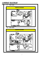
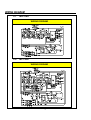
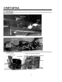
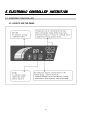
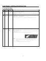
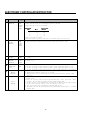
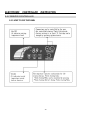
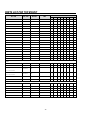
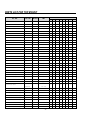
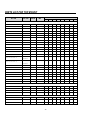
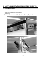
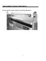
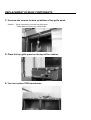
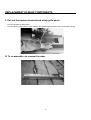
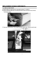
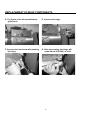
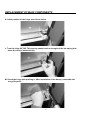
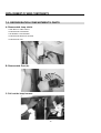
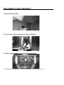
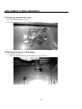
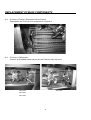
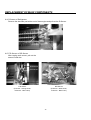
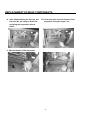
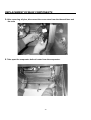
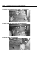
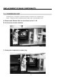
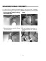
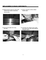
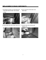
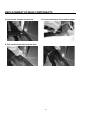
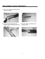
1250 Victoria street
Carson, CA 90746
U.S.A. & Canada Toll Free 1-800-627-0032
Fox Service 1-800-381-7770
TEL: 310-900-1000
FAX: 310-900-1077
www.turboairinc.com
1
Commercial
Refrigerator & Freezer
Service Manual
Solid Door
Model No. : TSR-23SD
TSR-35SD
TSR-49SD
TSR-72SD
TSF-23SD
TSF-35SD
TSF-49SD
TSF-72SD
2
TABLE OF CONTENTS
1. FEATURE CHART
1-1.
FRONT VIEW
1-2.
SIDE VIEW
2. WIRING DIAGRAMS
2-1. REFRIGERATOR (1DOOR): TSR-23SD
2-2. FREEZER (1DOOR): TSF-23SD
2-3. REFRIGERATOR (2DOOR): TSR-35SD
2-4. FREEZER (2DOOR): TSF-35SD
2-5. REFRIGERATOR (2DOOR): TSR-49SD
2-6.FREEZER (2DOOR): TSF-49SD
2-7. REFRIGERATOR (3DOOR): TSR-72SD
2-8.FREEZER (3DOOR): TSF-72SD
3. PART DETAIL
3-1.TOP GRILLE
3-2.REFRIGERATION COMPARTMENT
3-3.ELECTRICAL BOX
3-4.DOOR
3-5.COOLING COMPARTMENT
4. MAIN COMPONENTS
4-1.COMPRESSOR
4-2.COMPRESSOR RELAY
4-3.CONDENGSER DRYER
4-4.CAPACITOR
4-5.EVA FAN MOTOR
4-6.CONDENSOR FAN MOTOR
4-7.EVA DEFROST HEATER
4-8.LAMP
4-9.PCB TRANSFORMER
4-10.MAIN PCB
5. ELECTRONIC CONTROLLER INSTRUCTION
5-1. FREEEZER CONTROLLER
5-1-1. HOW TO USE THE PANEL
5-1-2.FUNCTION TABLE
5-1-3.ERROR CODE TABLE
5-2. REFRIGERATOR CONTROLLER
5-2-1.HOW TO USE THE PANEL
5-2-2. FUNCTION TABLE
5-2-3.ERROR CODE TABLE
6. SPARE PARTS LIST
7. REPLACEMENT OF MAIN COMPONENTS
7-1 .TOP GRILLE PARTS
7-2. REPLACING DOOR
7-3. REFRIGERATION COMPARTMENT’S PART.
7-4.CONDENSING UNIT
7-5 . REPLACING CABINET FRANME HEATER (AND/OR) MULLION HERTER
3
1.FEATURE CHART
1.1 FRONT VIEW
1 2 3 4
5 6
7
8
1
2
3
4
5
6
7
8
9
10
11
12
13
14
15
16
17
18
19
20
21
22
23
24
25
26
27
28
29
9
10
11
12
13
14
15
16
17
18 19 20 21 22
23 24
4
TOP GRILLE PANEL
TOP GRILLE
TOP GRILLE FIXTURE
DOOR SWITCH
TRANSFORMER
DOOR LOCK
MAIN PCB
DISPLAY PCB
CONTROL BOARD HOUSING
BRAND LOGO
DOOR HINGE TOP ASSEMBLY
DOOR HINGE SPRING
DOOR ASSEMBLY
DOOR HANDLE
DOOR HINGE BOTTOM ASSEMBLY
BOTTOM GRILLE ASSEMBLY
CASTER
DRAIN PAN
SUCTION PIPE
CAPILLARY TUBE
ELECTRICAL BOX
COMPRESSOR
CONDENSER FAN MOTOR
CONDENSER COIL
GRILLE FIXTURE
MULLION(CENTER POST)
MULLION HERTER
FRAME HEATER
FRAME COVER
FEATURE CHART
1.2 SIDE VIEW
30 31
32 33 34 35 36
37
30
31
32
33
34
38
42
39
43 44
45
35
36
37
38
39
40
41
42
43
40
41
46
44
45
46
5
DOOR BUSHING
DOOR GASKET
LAMP BULB
LAMP SOCKET
EVAPORATOR FAN
MOTOR BLADE
EVAPORATOR FAN MOTOR
EVAPORATOR COIL
SUCTION PIPE
EVAPORATOR FRAIN PAN
EVAPORATOR DRAIN ELBOW
DRAIN HOSE
SHELF STANDARD
LAMP SHIELD
EVAPORATOR FAN
MOTOR GUARD
DUCT (A) ’FRONT’
DUCT (B) ’BOTTOM’
SHELF
2.WIRING DIAGRAM
2-1
TSR-23SD
WIRING DIGRAM
2-2
TSF-23SD
WIRING DIGRAM
6
WIRING DIAGRAM
2-3
TSR-35SD
WIRING DIGRAM
2-4
TSF-35SD
WIRING DIGRAM
7
WIRING DIAGRAM
2-5
TSR-49SD
WIRING DIGRAM
2-6
TSF-49SD
WIRING DIGRAM
8
WIRING DIAGRAM
2-7
TSR-72SD
WIRING DIGRAM
2-8
TSF-72SD
WIRING DIGRAM
9
3.PART DETAIL
3-1. TOP GRILLE
Door Lock, Switch
Door Lock
Switch
Transformer, Main P.C.B
Transformer
Harness
Main P.C.B
3-2. Refrigeration Compartment
Cycle Assembly
Condenser Fan Motor Assembly
Suction Pipe
Condenser Coil Shroud
Compressor
Condenser
Condenser Pipe
Condenser Dryer
10
PART DETAILS
Drain Pan Assembly
Sop Paper Fixture
Sop Paper
Drain Pan
Condenser Fan Motor Assembly
Condenser Motor
Bracket
Condenser Fan Blade
3-3. Electrical Box
Power Busing
Power Relay
gB
11
PART DETAILS
3-4. Door
Gasket
Gasket
3-5. Cooling Compartment
Freezer Duct & Refrigerator Duct (TSR-35SD,TSF-35SD,TSR-49SD, TSF-49SD,
TSR-72SD, TSF-72SD Type)
Duct (A)
Evaporator Fan
Motor Guard
Duct (B)
Freezer Evaporator, Fan (TSF-49SD, TSF-72SD)
Evaporator Fan Motor Blade
Heater Connectors &
Sensor Connectors
Lamp Connector
Evaporator
Evaporator Thermal Fuse
12
PART DETAILS
Freezer Duct & Refrigerator Duct (TSR-23SD, TSF-23SD Type) Duct (B)
Evaporator Fan
Motor Guard
Duct (A)
Duct (B)
Freezer Evaporator, Fan (TSF-23SD)
Lamp & Fan Motor Connectors Evaporator Fan
Lamp & Fan Motor Connectors
EVAPORATOR
Evaporator
Fan Blade
Evaporator
Thermal
F-Sensor
Evaporator
Coil Heater
13
Heater Connectors &
Sensor Connectors t
4.MAIN COMPONENTS
4-1.COMPRESSOR
Model
TSR-23SD
TSR-35SD
Refrigerant
TSR-49SD
TSR-72SD
TSF-23SD
TSF-35SD
R-134a
TSF-49SD
R-404a
Voltage
115V/60HZ
Comp
TSF-72SD
208/230
HBL27YE-1
SK1A1C-L2W
SK1A1C-L2W
CAJ4476YC
CAE2420Z
CAJ2432Z
CAJ2432Z
CAJ2446Z
M369700100
M609700100
M609700100
P8R5700100
G2F5700100
P2F5700100
P2F5700100
P5F5700100
CSR
CSR
CSR
CSIR
CSIR
CSR
CSR
CSR
TSF-35SD
TSF-49SD
Model
Part code
Starting
Type
4-2.COMPRESSOR RELAY
Model
TSR-23SD
TSR-35D
TSR-49SD
TSF-23SD
Voltage
Relay
Model
TSR-72SD
115v/60HZ
783RHBZZ-52
795TFBZZ-53
795TFBZZ-53
TSF-72SD
220V/60HZ
MST16AHN-3240
GA3PJU0016
GA3PJU0016
CRA38014-3057
CRA38012-3057
4-3.CONDENSER DRYER
Model
TSR-23SD
TSF-23SD
TSR-35SD
TSF-35SD
TSR-49SD
TSF-49SD
TSR-72SD
TSF-72SD
Refrigerant
R-134a
R-404a
R-134a
R-404a
R-134a
R-404a
R-134a
R-404a
Spec.
C-052-S
Part code
M726800100
4-4.CAPACITOR
Model
TSR-23SD
TSR-35SD
TSR-49SD
Voltage
Running
TSF-23SD
TSF-35SD
TSF-49SD
TSR-72SD
115V/60HZ
115V/60HZ
X
TSF-72SD
220V/60HZ
X
Part
code
Starting
200V/100uf
200V/10 ㎌
125V/12 ㎌
160V/60Hz/
160V/60Hz
160V/315uF
160vac/250uF
250V/50Hz/
315uF-0+20%
/315uF-0+20%
-0+20%
-0+20%
88uF-0+20%
Part
code
14
MAIN COMPONENTS
4-5.EVA FAN MOTOR
Model
TSR-23SD
TSR-35SD
TSR-49SD
TSF-23SD
TSF-35SD
TSF-49SD
Voltage
115V/ 60Hz
Motor Model.
IS-4420DWSN-2A(CW) (43W)
Part code
TSR-72SD
TSF-72SD
P8F6600100
4-6.CONDENSOR FAN MOTOR
Model
TSR-23SD
TSR-35SD
TSR-49SD
TSF-23SD
Voltage
Motor
Model.
TSF-35SD
TSF-49SD
TSR-72SD
TSF-72SD
115V, 60Hz
220V, 60Hz
IS 4420DWSG-1
4420DWSQ-1
G8F6600100
G8F6600200
Part code
4-7.EVA DEFROST HEATER
Model
TSR-23SD
TSR-35SD
TSR-49SD
TSF-23SD
Voltage
TSF-35SD
TSF-49SD
TSR-72SD
TSF-72SD
115V/60HZ
Spec..
Part
code
X
X
X
X
X
X
445W
535W
600W
X
900W
T2F5300300
T3F5300100
T5F5300300
X
T8F5300500
4-8.LAMP
Model
TSR-23SD
TSR-35SD
TSR-49SD
TSF-23SD
TSF-35SD
Voltage
120V/60HZ
Spec..
40W
Part code
TSF-49SD
TSR-72SD
TSF-72SD
TSR-72SD
TSF-72SD
P996300100
4-9.PCB TRANSFORMER
Model
TSR-23SD
TSR-35SD
TSR-49SD
TSF-23SD
TSF-35SD
Voltage
115V/60HZ
Spec..
DWG-115V
Part code
P996000100
TSF-49SD
4-10.MAIN PCB
Model
TSR-23SD
TSR-35SD
TSR-49SD
Voltage
TSR-72SD
TSF-23SD
TSF-35SD
TSF-49SD
115V/60HZ
Spec..
Part
code
P8R5400100
P8F5400100
15
TSF-72SD
5.ELECTRONIC CONTROLLER INSTRUTION
5-1.FREEZER CONTROLLER
5-1-1.HOW TO USE THE PANEL
16
ELECTRONIC CONTROLLER INSTRUCTION
5-1-2.FUNCTION TABLE
NO
FUCTION
1
Initial
Operation
2
Temperature
Control
3
Turbo
Freeze
Controlled
Part
Buzzer, Fan
Or Door lamp
Bar LED
88LED
Compressor
F-fan
C-fan
LED
Compressor
F-fan
C-fan
LED
Description
1.Buzzer will ring 2 sec. after Plug-In.
2.88LED displays inside temperature.
3.Compressor runs immediately ,if evaporator temperature is higher than 38.3°F(3.5°
C).Compressor will run 3 minutes after plug-in, if eva. temp. is lower than 38.3°
F(3.5°C).
1.The temperature can be changed by pushing up/down buttons.
2.88LED displays inside temperature .
3.Buzzer buzzes 1 time whenever a button is pressed.
4.Compressor automatically turns on and off by F-sensor(Except error mode)
1.If Turbo Freeze button is pressed, Turbo Cooling mode will start.
2.If the Turbo Freeze button is pressed during Turbo Freeze mode, Turbo Freeze mode
can be canceled.
3.During Turbo Freeze mode, the temperature control button will not affect the
temperature control.
4.All bar LEDs are fully lighted during Turbo Freeze mode.
*NOTE*
F-sensor: Thermistor (Electrical resistance varies with temperature changing)
Act Like thermostat. Detect air temp. Wire color is orange.
D-sensor: Thermistor
Act like defrost terminator. Wire color is blue.
17
ELECTRONIC CONTROLLER INSTRUCTION
NO
4
FUCTION
Defrost
Function
5
Comp
F-fan
C-fan
Heater
a. Press and hold up/down button and press turbo freeze button 5 time
Comp Restart
Prevent
Power Failure
Back-Up
Function
Comp
C-fan
Comp
F-fan
C-fan
1.
Door opening
Alarm function
Buzzer
LED
1.
2.
3.
4.
1.
2.
3.
Forced
Defrost
6
7
8
9
Controlled
Description
Part
Heater
1.Defrost function is controlled by time interval setting.
com2.Time interval can be set by shifting dip s/w on the PCB.
pressor
3.Time interval setting is as follows.
F-fan
C-fan
Dip Switch
Cycle time
No.1
No.2
(hours)
0
0
12
1
0
10
0
1
8
1
1
6
4.Factory setting is 6 hours
5.The first defrost function will start at the half value of setting time.
Buzzer
Buzzer
Function
10
LED
Error
Display
After comp. is off, comp. will not start for 3 min, even though the F-sensor is at
point.
1. Compressor will not start for 3 min. after power failure.
2. F-fan is on.
If door is opened , fan goes off and lamp on.
If door is opened for more than 30 seconds, chirpy sound alarm buzzes 3 time.
If door is opened for more than 60 seconds, chirpy sound alarm buzzes 5 time.
If door is opened for more than 5 minutes ,chirpy sound alarm buzzes continuously
Alarm buzzers 1 time after initial power on.
Alarm buzzers whenever each button is pressed.
Alarm buzzers if door remains open for certain period.(See door opening alarm
function).
1. If inside temp. is lower than -50°F or higher than 69,88LED indicates‘Lo’ or‘Hi’
respectively.
2. Press‘up’ button 5 times with pressing and holding both ‘down’ button and ‘Turbo
Cooling’ button .Above procedure switches normal display mode.
3. If there was no error occurred before, there will be no change on the 88 LED. If there
was any error occurred before ,there will display error code.
4. Next error code will be displayed by pressing down button.
5. 10 seconds after the last button pressed, error display mode will be switch
to normal
display mode.
18
ELECTRONIC CONTROLLER INSTRUCTION
5-1-3.ERROR CODE TABLE
Code
Content
Perception Method
F1
F-sensor
Malfunction
-short circuit
-wire disconnection
-The comp. runs by periods.
-Above action will repeat until fixed.
D1
D-sensor
Malfunction
-short circuit
-Heater turns on a regular basis
Irrespective of D-sensor.
-wire disconnection
Refrigerator operation state
C1
Cycle, Comp
Malfunction
-Normal operation
F3
Defrost
-Reattempt normal defrost function repeatedly.
Malfunction
19
ELECTRONIC
CONTROLLER
INSTRUCTION
5-2.FREEZER CONTROLLER
5-2-1.HOW TO USE THE PANEL
20
ELECTRONIC
NO
FUCTION
1
Initial
Operation
2
Temperature
Control
3
Turbo
Cooling
CONTROLLER
INSTRUCTION
Controlled
Part
Buzzer ,Fan
Or Door lamp
Bar LED
88LED
1.Buzzer will ring 2 sec. after Plug-In.
2.88 LED displays micom version initially and does inside temperature in 2 sec.
3.Compressor runs ,if evaporator temperature is higher than 41.0°F(5.0°C).Compressor
will run 3 minutes after plug-in, if eva. temperature is lower than 41.1°F(5.0°C)
Compressor
F-fan
C-fan
LED
1.The temperature can be changed by pushing up/down buttons.
2.88LED displays inside temperature .
3.Buzzer buzzes 1 time whenever a button is pressed.
4.Compressor automatically turns on and off by D-sensor(Except error mode)
Compressor
F-fan
C-fan
LED
Description
1.If Turbo Cooling button is pressed, Turbo Cooling mode will start.
2.If the Turbo Cooling button is pressed during Turbo Cooling mode, Turbo Cooling mode
can be canceled.
3.During Turbo Cooling mode, the temperature control button will not affect the
temperature control.
4.All bar LEDs are fully lighted during Turbo Cooling mode.
*NOTE*
D-sensor: Thermistor (Electrical resistance varies with temperature changing)
ACT Like thermostat. Detect eva. coil's temp. Wire color blue.
R-sensor: Thermistor
Act like thermometer. Detect inside air temp. Wire color is white.
21
ELECTRONIC
NO
4
FUCTION
Defrost
Function
CONTROLLER
Controlled
Part
Heater
compressor
F-fan
C-fan
INSTRUCTION
Description
1.Defrost function is controlled by time interval setting.
2.Time interval can be set by shifting dip s/w on the PCB.
3.Time interval setting is as follows.
Dip Switch
Cycle time
No.1
No.2
(hours)
0
0
12
1
0
10
0
1
8
1
1
6
4.Factory setting is 6 hours
5.The first defrost function will start at the half value of setting time.
a.Press and hold up/down button and press turbo freeze button 5 times.
5
Forced
Defrost
Comp
F-fan
C-fan
Heater
6
Comp Restart
Prevent
Power
Failure
Back-Up
Function
Door
opening
Alarm
function
Comp
C-fan
1.After comp. is off, comp. will not start for 3 min, even though the F-sensor is at
point.
Comp
F-fan
C-fan
1.Compressor will not start for 3 min. after power failure.
2.F-fan is on.
Buzzer
LED
1.If
2.If
3.If
4.If
9
Buzzer
Function
Buzzer
1.Alam buzzers 1 time after initial power on.
2.Alam buzzers whenever each button is pressed.
3.Alam buzzers if door remains open for certain period.(See door opening alarm
function).
10
Error
Display
LED
1.If inside temp. is lower than -50°F or higher than 69,88LED indicates‘Lo’ or
‘Hi’
respectively.
2.Press‘up’ button 5 times with pressing and holding both ‘down’ button and ‘Turbo
Cooling’ button .Above procedure switches normal display mode.
3.If there was no error occurred before, there will be no change on the 88 LED. If
there was any error occurred before ,there will display error code.
4.Next error code will be displayed by pressing down button.
5.10 seconds after the last button pressed, error display mode will be switch to
normal display mode.
7
8
door
door
door
door
is
is
is
is
opened
opened
opened
opened
,fan goes off
for more than
for more than
for more than
22
and lamp on.
30 seconds ,chirpy sound alarm buzzes 3 time.
60 seconds ,chirpy sound alarm buzzes 5 time.
5 minutes ,chirpy sound alarm buzzes continuously
5-2-3.ERROR CODE TABLE
Code
Content
F1
F-sensor
Malfunction
-short circuit
-wire disconnection
Perception Method
-The comp runs by periods
-Above action will repeat until fixed
D1
D-sensor
Malfunction
-short circuit
-Heater turns on a regular basis
Irrespective of D-sensor
-wire disconnection
Refrigerator operation state
C1
Cycle, Comp
Malfunction
-Normal operation
F3
Defrost
Malfunction
-Reattempt normal defrost function repeatedly.
23
6.PARTS LIST FOR TOP MOUNT
Model
Part Name
Part Code
Material
SPEC
R-23S
F-23S
R-35S
F-35S
R-49S
F-49S
R-72S
F-72S
1
1
Caster
CASTER BOX ASS'Y
P8F0800300
CASTER BOX ASS'Y
P8F0800400
1
1
1
1
1
1
Compressor
COMPRESSOR RUN CAPACITOR
COMPRESSOR START CAPACITOR
COMPRESSOR
G2F5700100
COMPRESSOR
M369700100
CSIR (CAJ 2420Z)
1
CSR HBL-27YE-1
1
(1/4HP)
CSR SK1A1C-L2W
COMPRESSOR
M609700100
1
1
(1/3HP)
COMPRESSOR
P2F5700100
CSR (CAJ2432Z)
COMPRESSOR
P5F5700100
CSR (CAJ2446Z)
COMPRESSOR
P8R5700100
CSIR (CAJ4476Y)
1
1
1
1
COMPRESSOR POWER CORD
T2F5100301
1
(HARNESS RELAY)
COMPRESSOR POWER CORD
T3F5100200
1
(HARNESS RELAY)
COMPRESSOR POWER CORD
1
T3R5100200
(HARNESS RELAY)
COMPRESSOR POWER CORD
T5R5100101
1
(HARNESS RELAY)
COMPRESSOR POWER CORD
T8F5100101
1
(HARNESS RELAY)
COMPRESSOR POWER CORD
T8R5100101
1
1
1
1
1
(HARNESS RELAY)
POWER RELAY (COMP.RELAY)
LS 산산
P995900200
1
1
1
1
1
1
ELECTRICAL BOX HARNESS
T5R5100300
1
1
1
(HARNESS MIDDLE)
ELECTRICAL BOX HARNESS
T8F5100300
1
(HARNESS MIDDLE)
ELECTRICAL BOX HARNESS
T8R5100300
1
1
1
(HARNESS MIDDLE)
MAIN POWER CORD
T8F5800200
MAIN POWER CORD
T8R5800100
1
1
1
Condenser
CONDENSER COIL
G2F4500103
CU
CONDENSER COIL
G2R4500102
CU
1
1
24
1
1
1
1
1
PARTS LIST FOR TOP MOUNT
Model
Part Name
Part Code
Material
SPEC
R-23S
CONDENSER COIL
G5R4500102
CU
CONDENSER COIL
G8F4500102
CU
CONDENSER COIL
G8R4500102
CU
SUCTION PIPE (B)
T2F4200401
CU
SUCTION PIPE (B)
T2R4200301
CU
SUCTION PIPE (B)
T3F4200100
CU
SUCTION PIPE (B)
T3R4200300
CU
SUCTION PIPE (B)
T5R4200301
CU
SUCTION PIPE (B)
T8F4200301
CU
SUCTION PIPE (B)
T8R4200201
CU
HARD CORE DRYER
M726800100
F-23S
R-35S
F-35S
1
R-49S
F-49S
R-72S
F-72S
1
1
1
1
1
1
1
1
1
1
1
1
1
1
1
1
1
1
1
1
1
Condenser Fan
30218B0100,
CONDENSER FAN MOTOR BLADE
AL
CCW 흡흡 225
AL
CCW 흡흡 250
1
1
1
2
P8F2700300
30218A0100,
CONDENSER FAN MOTOR BLADE
1
1
1
1
1
1
G8F2700500
3963220410,
IS 4420DWSG-1
G8F6600100
(CCW) (115V-47W)
3963322020,
IS 4420DWSQ-1
G8F6600200
(CCW) (220V-43W)
CONDENSER FAN MOTOR
1
1
1
1
1
CONDENSER FAN MOTOR
2
Door
3007H1000,
DOOR BUSHING
NY66
1
1
2
2
2
2
3
3
NY66
1
1
2
2
2
2
3
3
1
1
1
1
1
1
1
1
B1R0500500
DOOR BUSHING
T8F0500700
ASS'Y DOOR PANEL (L)
T3F0500200
ASS'Y DOOR PANEL (L)
T5F0500200
ASS'Y DOOR PANEL (M)
T8F0500100
ASS'Y DOOR PANEL (R)
T2F0500100
ASS'Y DOOR PANEL (R)
T3F0500100
ASS'Y DOOR PANEL (R)
T5F0500100
DOOR GASKET
T3F0500300
PVC
DOOR GASKET
T8F0500401
PVC
T3F0500500
SWRM
φ3.5
T8F0500600
SWRM
φ3.8
DOOR CUSHION
T8F9900601
RUBBER
DOOR STOPER (B)
B1R0500600
SUS304-2B
DOOR STOPPER SPACE
T8F2900700
CR
1
1
1
2
1
1
1
1
1
1
2
2
3
3
2
2
3
3
2
1
DOOR HINGE SPRING (SPRING
2
2
BAR)
DOOR HINGE SPRING (SPRING
1
1
BAR)
1
1
25
1
2
2
2
2
2
2
3
3
3
2
2
PARTS LIST FOR TOP MOUNT
Model
Part Name
Part Code
Material
SPEC
R-23S
F-23S
CABINET HEATER
T2F5300100
PVC
L=3700,54W
CABINET HEATER
T2R5300100
PVC
L=3700,43.7W
CABINET HEATER
T3F5300300
PVC
CABINET HEATER
T3R5300100
PVC
CABINET HEATER
T5F5300100
PVC
L=5100,74.5W
CABINET HEATER
T5R5300100
PVC
L=5100,60.2W
CABINET HEATER
T8F5300200
PVC
L=6490,94.8W
CABINET HEATER
T8R5300200
PVC
L=6490,76.6W
MULLION COVER (A)
T8F1200600
SUS439-#4
MULLION COVER (B)
T8F1200500
SUS439-#4
MULLION HEATER
(VER)
T8F5300101
PVC
L=2530,28.6W
MULLION HEATER
(VER)
T8R5300101
PVC
L=2530,21W
DOOR HINGE TOP ASSEMBLY LEFT
T8F2900300
CR
DOOR HINGE TOP ASSEMBLY RIGHT
T8F2900400
CR
1
TOP HINGE SPACER
T8F2900500
PVC
1
DOOR HINGE BOTTOM ASSEMBLY LEFT
T8F2900100
SUS304-2B
DOOR HINGE BOTTOM ASSEMBLY RIGHT
T8F2900200
SUS304-2B
1
BOTTOM HINGE SPACE
T8F2900600
PVC
1
DRAIN PAN
30211A0202
PP
DRAIN CASE
T2F1900100
ABS
1
1
T2F0400400
ABS
1
1
T8F0400700
ABS
DRAIN WICKING PADS (SOP PAPER)
T2F0400500
PAPER
DRAIN WICKING PADS (SOP PAPER)
T8F0400800
PAPER
DRAIN CONNECTOR A
G8F3200601
NY66
1
DRAIN CONNECTOR B
G8F3200700
NY66
EVAPORATOR DRAIN PAN
G2F2700100
AL
EVAPORATOR DRAIN PAN
T3F2700100
AL
EVAPORATOR DRAIN PAN
G5F2700101
AL
EVAPORATOR DRAIN PAN
G8F2700100
AL
R-35S
F-35S
R-49S
F-49S
R-72S
F-72S
1
1
1
1
1
1
1
1
1
1
1
1
1
1
1
1
1
1
2
2
1
1
1
1
2
2
1
1
1
1
1
2
2
1
2
2
2
2
3
3
1
1
1
1
1
1
1
1
1
1
1
2
2
1
2
2
2
2
3
3
1
1
1
1
1
1
1
1
1
1
1
1
4
4
4
4
4
4
1
1
1
1
1
1
1
1
1
1
1
1
1
1
1
1
1
1
1
1
1
1
1
Drain
2t
DRAIN WICKING BAR
(SOP PAPER FIXTURE)
DRAIN WICKING BAR
(SOP PAPER FIXTURE)
4
4
Evaporator
26
PARTS LIST FOR TOP MOUNT
Model
Part Name
Part Code
Materi
Material
SPEC
R-23S
F-23S
EVAP COIL
G2F4400104
CU
EVAP COIL
G2R4400101
CU
EVAP COIL
T3F4400100
CU
EVAP COIL
T3R4400100
CU
EVAP COIL
G5F4400103
CU
EVAP COIL
G5R4400101
CU
EVAP COIL
G8F4400101
CU
EVAP COIL
G8R4400101
CU
DEFROST HEATER
T2F5300300
SUS-PIPE
DEFROST HEATER
T3F5300100
SUS-PIPE
DEFROST HEATER
T5F5300300
SUS-PIPE
600W
DEFROST HEATER
T8F5300500
SUS-PIPE
900W
DEFROST FIXTURE SPRING
G8F9900101
SUS304
EVAPORATOR SENSOR (THERMISTOR ASSY)
T8F6200101
D-SENSOR, F-SENSOR
EVAPORATOR SENSOR (THERMISTOR ASSY)
T8R6200101
D-SENSOR, R-SENSOR
EVAPORATOR THERMAL FUSE
T8F6200200
115V 60Hz 80 도
1
EVAPORATOR DRAIN PAN HEATER
T2F5300200
PVC&AL
L=3460,61.2W
1
EVAPORATOR DRAIN PAN HEATER
T3F5300200
PVC&AL
EVAPORATOR DRAIN PAN HEATER
T5F5300200
PVC&AL
L=5060,90W
EVAPORATOR DRAIN PAN HEATER
T8F5300400
PVC&AL
L=6260,111.1W
DRAIN HOSE HEATER
T8F5300300
DRAIN PAN INSULATOR (DRAIN GUIDE PAD)
G8F7300100
F-PS
DRAIN PAN INSULATOR (DRAIN GUIDE PAD)
G5F7300100
F-PS
DRAIN PAN INSULATOR (DRAIN GUIDE PAD)
G2F7300100
F-PS
DRAIN PAN INSULATOR (DRAIN GUIDE PAD)
T3F7300100
F-PS
EVAPORATOR FAN MOTOR GUARD
G8F3200501
ABS
EVAPORATOR FAN MOTOR BLADE
P8F2700400
AL
1
1
1
445W
1
1
1
1
DUCT (A),(EVAP HOUSING COVER (F))
G5F1700101
AL
DUCT (A),(EVAP HOUSING COVER (F))
T2F1700100
AL
DUCT (A),(EVAP HOUSING COVER (F))
T8F1700100
AL
DUCT (B),(EVAP HOUSING COVER (B))
T2F1700200
AL
DUCT (B),(EVAP HOUSING COVER (B))
T3F1700100
AL
DUCT (B),(EVAP HOUSING COVER (B))
G5F1700200
AL
DUCT (B),(EVAP HOUSING COVER (B))
G8F1700200
AL
12
12
12
12
1
1
1
1
1
1
1
1
1
1
1
1
1
1
1
1
CW 흡흡 175
(CW) (43W)
AL
F-72S
1
P8F6600100
T3F1700200
R-72S
1
IS 4420DWSN-2A
DUCT (A),(EVAP HOUSING COVER (F))
F-49S
1
3963328120,
AL
R-49S
1
EVAPORATOR FAN MOTOR
T3F1700300
F-35S
1
L=700,10W
DUCT (A),(EVAP HOUSING COVER (F))
R-35S
1
1
1
1
1
1
1
1
1
1
1
1
2
2
2
2
3
3
1
1
2
2
2
2
2
2
1
1
2
2
2
2
2
2
1
1
1
1
1
1
1
1
1
1
1
1
1
1
1
27
1
PARTS LIST FOR TOP MOUNT
Model
Part Name
Part Code
Materi
Material
SPEC
R-23S
F-23S
R-35S
F-35S
R-49S
F-49S
R-72S
F-72S
Top Grille Panel
TOP GRILLE PANEL ASSEMBLY
T2F0600200
0
TOP GRILLE PANEL ASSEMBLY
T2R0600100
TOP GRILLE PANEL ASSEMBLY
T3F0600500
TOP GRILLE PANEL ASSEMBLY
T3R0600100
TOP GRILLE PANEL ASSEMBLY
T5F0600200
TOP GRILLE PANEL ASSEMBLY
T5R0600100
TOP GRILLE PANEL ASSEMBLY
T8F0600500
TOP GRILLE PANEL ASSEMBLY
T8R0600100
BRAND LOGO(F)
T8F0900100
ABS
BRAND LOGO(R)
T8F1600800
ABS
TOP GRILLE
T2F0600101
SUS439-2B
TOP GRILLE
T3F1600100
SUS439-#4
TOP GRILLE
T5F0600101
SUS439-2B
HARNESS DISPLAY PCB
P8F5101201
1
1
1
1
0
1
1
1
1
1
1
1
1
1
1
1
1
1
1
1
1
1
1
1
1
1
1
1
1
1
30235L0100,
FRONT PCB CASE FILM (F)
1
1
1
1
P8F7400100
30235Q0900,
FRONT PCB CASE FILM (R)
1
1
1
1
P8R7400100
KEY
P998200100
1
1
2
2
DISPLAY PCB
P995400100
1
DISPLAY PCB
P8F5400200
1
1
1
1
MAIN PCB (F)
P8F5400100
1
1
1
1
MAIN PCB (R)
P8R5400100
1
TRANS FORMER
P996000100
1
1
1
1
1
1
1
1
POWER SWITCH
30281Q0100
1
1
1
1
1
1
1
1
DOOR SWITCH
P995200100
1
1
2
2
2
2
3
3
BOTTOM GRILLE ASSEMBLY
T2F1600100
1
1
BOTTOM GRILLE ASSEMBLY
T3F0600600
1
1
BOTTOM GRILLE ASSEMBLY
T5F1600100
1
1
BOTTOM GRILLE ASSEMBLY
T8F1600100
1
1
1
2
2
1
1
3
3
1
1
1
Bottom Gr
Grille
Lamp
LAMP COVER
G8F3200203
LAMP BULB
P996300100
LAMP SOCKET
P996400100
PC
ABS
1
1
1
1
1
1
1
1
1
1
1
1
1
1
2
2
1
1
1
1
1
1
1
1
28
PARTS LIST FOR TOP MOUNT
Model
Part Name
Part Code
Material
SPEC
R-23S
F-23S
R-35S
F-35S
R-49S
F-49S
R-72S
F-72S
16
16
26
26
32
32
48
48
3
3
6
6
6
6
9
Shelf
SHELF CLIP
P993200800
PA-66
SHELF
T2F1800101
SUS304
SHELF
T3F1800100
SUS304
SHELF
T5F1800100
SUS304
SHELF
T8F1800200
SUS304
Natural
9
29
8.REPLACEMENTOFMAINCOMPONENTS
7-1. TOP GRILLE PARTS
- MAIN PCB or TRANSFORMER
- DISPLAY PCB
- DOOR LOCK or POWER SWITCH (ROCKER SWITCH)
- DOOR SWITCH
A. Unscrew the screw located both sides of top grille panel.
30
REPLACEMENT OF MAIN COMPONENTS
B. Unscrew the screws located on top of top grille panel.
31
REPLACEMENT OF MAIN COMPONENTS
C. Unscrew the screws located on bottom of top grille panel.
* Caution
:When unscrewing, hold the top grille panel.
Falling down top grille may cause bruise.
D. Place the top grille panel on the top of the cabinet.
E. You can replace PCB transformer.
32
REPLACEMENT OF MAIN COMPONENTS
F. Pull out the harness located back of top grille panel.
You can separate top grille panel.
You can replace power switch (rocker switch), door switches (lamp switch) and control board housing
G. To re-assemble, do reversed in order.
33
REPLACEMENT OF MAIN COMPONENTS
7-2. REPLACING DOOR
A. Disassemble top grille panel as described section 7-1 A.B.C.D.
B. Remove Bottom Grille by unscrewing the four screws located on each side of
The Bottom Grille.
C. Open the electrical box. Then uncap the door heater wire. (Freezer model only)
34
REPLACEMENT OF MAIN COMPONENTS
D. The figure of the disassembled top
grille panel.
E. Unscrew the hinge
F. Unscrew the last screw with pushing
the hinge.
G. After unscrewing, the hinge will
rotate about 90°(CCW), of itself.
35
REPLACEMENT OF MAIN COMPONENTS
H. Lift the door and pull out the door heater’s lead wire.
I.
Replace the door with the new one
J. Ready
the hinge as below. It is important to set initial position (angle).
36
REPLACEMENT OF MAIN COMPONENTS
K. Initial position of the hinge must be as below.
L. Turn the hinge 90° CW. This turning cause torsio n strength of the bar spring that
shuts the door(s) automatically.
M. Screw the hinge with pushing it. After installation of the door(s), assemble the
top grille panel.
37
REPLACEMENT OF MAIN COMPONENTS
7-3. REFRIGERATION COMPARTMENT’S PARTS
A. Disassemble lamp shield.
- LAMP BULB or LAMP SHIELD
- EVAPORATOR FAN MOTOR
- F/D SENSOR or R/D SENSOR
- EVAPORATOR DEFROST HEATER
- EVAPORATOR COIL
B. Disassemble Duct (A).
C. Pull out the lamp harness.
38
REPLACEMENT OF MAIN COMPONENTS
D. Disassemble duct (B).
E. Pull-out the evaporator drain pan heater’s lead wire.
F. Figure of disassembled refrigeration compartments
In this situation, you can replace fan motor, F/D-sensor, Evaporator coil, ETC
39
REPLACEMENT OF MAIN COMPONENTS
G. Replacing evaporator fan motor
G-1 . Pull out the fan motor’s connector.
G-2 . Unscrew the four screws which located on bottom of fan motor
H. Replacing F/D-Sensor or R/D-Sensor
H-1. F-Sensor of Freezer
Unscrew as illustrated below and pull-out the F-Sensor from the cover
F-Sensor
(Orange Color)
40
REPLACEMENT OF MAIN COMPONENTS
e
H-2.
D-Sensor of Freezer (Evaporator Defrost Sensor)
Disassemble the D-Sensor from evaporator’s end plate.2
D-SENSOR
(BLUE COLOR)
H-3.
R-Sensor of Refrigerator
Unscrew as illustrated below and pull-out the R-Sensor from the cover.
R-SENSOR
(WHITE COLOR)
R-SENSOR
(WHITE COLOR)
UNSCREW
UNSCREW
TSR-35SD
TSR-23SD
TSR-49SD
TSR-72SD
41
REPLACEMENT OF MAIN COMPONENTS
H-4. D-Sensor of Refrigerator
Remove the absorber pad at the end of thermo-pipe and pull-out the D-Sensor.
D-SENSOR
(BLUE COLOR)
THREM-PIPE
H-5. F/D Sensor or R/D Sensor
After unplug each sensor, pull-out the
sensor’s lead wire.
D-SENSOR
D-SENSOR
F-SENSOR
D-SENSOR
F/D Sensor
R/D Sensor
(F-Sensor : Orange Color,
(R-Sensor : White Color,
D-Sensor : Blue Color)
D-Sensor : Blue Color)
42
REPLACEMENT OF MAIN COMPONENTS
A. After disassembling the duct (A) and
the duct (B), get ready as below for
replacing the evaporator defrost
heater.
B. Pull out the pins from the bottom of the
evaporator using the nipper, etc.
C. Split the hooks of the evaporator.
43
REPLACEMENT OF MAIN COMPONENTS
D. After removing all pins, disconnect the connectors from the thermal fuse and
the main
E. Take apart the evaporator defrost heater from the evaporator.
.
44
REPLACEMENT OF MAIN COMPONENTS
F. Install the new evaporator defrost heater in original position.
G. Pat the evaporator defrost heater with the soft hammer.
H. Pinch the hooks of the evaporator.
45
REPLACEMENT OF MAIN COMPONENTS
I . Assemble the pins in original positions.
J. Connect the connectors of the evaporator defrost heater to them of the thermal
fuse and the main harness.
* NOTE
Why is always 115 voltage detected between connectors of the evaporator defrost
heater
in the main harness?
The SNUBBER (located Main PCB) holds two AC power lines simultaneously.
The SNUBBER prevents Main PCB malfunction from sparks occurred by other electrical
component’s ON/OFF. (SNUBBER = Spark killer)
Because of the SNUBBER, 115 voltage is always detected, but electrical current in this case is
very little(small Amps.). So, this electrical current is not enough to operate the evaporator
defrost heater.
How to measure the Amps of a evaporator defrost heater.
Disconnect the connectors of the evaporator defrost heater.
Then, prepare the additional Power Source (115V/60Hz) and the Amp. Meter.
Connect the evaporator defrost heater to the additional power source and read amp. value from
the Amp. Meter.
46
REPLACEMENT OF MAIN COMPONENTS
7-4. CONDENSING UNIT
- Condensing Units : Compressor, Condenser Fan Motor, Condenser Coil, Condenser Dryer....
- Others : Compressor Power Cord (Relay harness), Main Power Cord, Electrical Box, ETC.
A. Disassemble Bottom Grille as described section 7-2. B.
B. Unscrew two screws as below.
C. Unplug the compressor’s power plug
47
REPLACEMENT OF MAIN COMPONENTS
D. Pull-out the condensing unit
48
REPLACEMENT OF MAIN COMPONENTS
7-5. REPLACING CABINET FRAME HEATER (and/or) MULLION
A. Insert the and edge of ‘–’type screw
driver into the gap between the frame
and the frame cover.
C. Separate the frame cover by sliding
the screw driver.
HEATER
B. Take apart the frame cover from the
frame.
D. Do just like above instructions in
other parts (bottom side, right side
and top
49
REPLACEMENT OF MAIN COMPONENTS
E. Below picture shows the inlet of the
cabinet frame heater toward the
electrical box.
F. Uncap connectors of the cabinet
frame heater.
G. Pull out the heater wire from
the inlet.
H. Insert the new cabinet frame heater
wire to the inlet, after surrounding it
along the frame.
50
REPLACEMENT OF MAIN COMPONENTS
I. Assemble the frame cover with the frame.
Push and slide the frame cover toward
corner.
J. Fit the end lines of the frame cover
Each other.
K. Fit the other side of the frame cover, too.
L. Pat the frame cover with the soft
hammer, etc.
51
REPLACEMENT OF MAIN COMPONENTS
M. Do like above instructions in other parts (Left side, right side and top side).
52
REPLACEMENT OF MAIN COMPONENTS
N. Unscrew the screws from the mullion. O. Take apart the mullion cover from the
mullion.
P. Take care for the mullion heater not to
be hurt. (It does not matter, if this
heater is out of order).
53
REPLACEMENT OF MAIN COMPONENTS
Q. Pull out the insulator from inside.
R. Uncap connectors of the mullion heater.
S. Pull out the heater wire from the inlet
54
REPLACEMENT OF MAIN COMPONENTS
T. Pull out the mullion cover(SUS) from the
mullion cover (ABS).
U. Change the old mullion heater and
install the new one with the gap between
wires 1.2 inch.
V. Insert the mullion cover(SUS) into the
original position.
55
REPLACEMENT OF MAIN COMPONENTS
W. Connect the heater wires with the main harness and the electrical box harness
X. Cover the caps on the connection parts and press them tightly.
56


![Maximum Model service Manual.ppt [호환 모드]](http://vs1.manualzilla.com/store/data/006002079_1-f9e925e4876feffe85b493d91263fd66-150x150.png)