1
.,.
Downloaded by
RadioAmateur.EU
The Siltronix Model 1011B Single SidebandTransceiveris
designedto be used in SSB, AM, or CWmodesin the 10
meter amateurradio band. In addition, the 1011B is alsoa
tunable receiverin the CBband.
Powerinput exceeds260 watts, P.E.P.,on singlesideband,
60 watts on AM, and 180 watts on CW. The Modell 011B
includesautomaticgain control (AGC),automatic levelcontrol (ALC), and grid block keying.
The internal AC power supply permits fIXed station or portable operation wherever 117 volts, 50-60 Hertz is available.
Export models for 208-220-240volts are availableon special order.
For 12-14volts DC operation in mobile,marine or portable
applications,a DC converterunit, model14A is available. It
attachesto the back of the 1011B in placeof the AC power
cord connector. Its dimensionsare only I ~ x 3 x 4 in.
The Model 1011 B generates a single sideband signal by
means of a crystal lattice filter, and the transceive operation
automatically tunes the transmitter to the received frequency. Provisions are included in the transceiver for oper.ation on either upper or lower sideband.
FREQUENCY RANGES
28.0-28.5MHz
28.5-29.0MHz
29.0-29.5MHz
29.2-29.7MHz
26.96-27.26MHz (Receiveonly)
(
REAR PANEL CONTROLS AND CONNECTIONS
P.A. BIAS Potentiometer,AUX RELAY jack, CW KEY
jack, Outboard VFO Connector, HEAD PHONESjack,
Fuse Holder,Antenna Connector,Jonesplug Powerconnector, S-MeterZero.
OTHER CONTROLS AND CONNECTIONS
POWER INPUT
SingleSideband,Suppressed
Carrier:
260 watts,P.E.P.minimum
CW: 180watts,DC input
AM: (SingleSidebandwith Carrier):
60 watts DC input
DISTORTioN
Distortion productsdown approx. 30 db.
UNWANTED SillEBAND SUPPRESSION.Unwanted
sidebanddownmore than 50 db.
CARRIER SUPPRESSION
Carrier suppression greater than 50 db.
Carrier Balance Control. Located on bottom Cover.
VOX CONNECTOR. Located on side of the chassis.
VACUUM TUBE COMPLEMENT
J' VI
V2
V3
V4
V5
V6
V7
V8
V9
VlO
VII
V12
V13
V14
l2BA6
l2BE6
6GK6
6LF6
6BZ6
l2BE6
l2BA6
l2BA6
l2AX7
6AV6
6GW8
l2BA6
6JH8
l2AX7
VFO Amplifier
TransmitterMixer
Driver
Power Amplifier
ReceiverRF Amplifier
ReceiverMixer
First IF Amplifier
SecondIF Amplifier
ProductDetector/ReceiveAudio
AGC Amplifier/Rectifier
AF Output
100 KC Calibrator
BalancedModulator
Microphone Amplifier
RECEIVER SENSITIVITY
Less than 0.5 microvolt at 50 ohms impedance for signalplus-noise to noise ratio of 10 db.
AUDIO OUTPUT AND RESPONSE
Audio output, 3 watts to 3.2 ohm load. Responseessentially flat from 300 to 3000 cps in both receive and
TRANSISTO R COMPLEMENT
Ql
Q2
Q3
2N706 Oscillator
2NS130 Buffer
2N706 CarrierOscillator
transmit.
TRANSMITTER OUTPUT
Wide-rangePi-network output matchesresistiveloads
from 50 to 75 ohms.
METERING
POWER REQUIREMENTS
117 VAC, S0-60 Hz at 4 amps. (208-220-240volt, SO60 Hz at 2.Samps.,export model). 12-14volts DC operation with model l4-A converterunit pluggedinto back
of 10118. Current drain: 8 amps,receivemode. 12
ampsaveragewith voice modulation, 2Sampsmaximum
in TUNE position.
Power amplifier cathode current 0-400 ma. on transmit,
S-Meter0-70 db over 59 on receive,Relative Output in
TUNE-CW.
FRONTPANELCONTROLS
A.F. GAIN, R.F. GAIN, Sideband Selector,Function
DIMENSIONS
Height
Width
Depth
5*- in.
13 in.
11 in.
Switch (CAL REC. TUNE-CW), Meter Switch, Tuning
Dial, Dial Set, SPOT Switch, ANL Switch, P.A. LOAD,
P.A. TUNE, Band Switch, CARRIER INSERTION,
DRIVER Control, MIC jack, MIC.GAIN.
2
~,.,
=::.c
WEIGHT
Weight
241bs.
Downloaded by
RadioAmateur.EU
GENERAL
The installation of the Siltronix 1011 B is not at all difficult,
and it involves only the placement of the transceiver in its
operational area (fixed or mobile); connection of power
(either 117 volts AC, or 12 volts DC); and the connection
of an antenna. The following paragraphs are therefore
devoted to the installation requirements involving micro.
phones, fIXed and mobile operation, and recommended
antenna types. Before actual installation, be sure to check
for possible shipment damage. Remove the cabinet (three
screws on each side), and check to make sure that all tubes
are fIrmly in place. Remove packing from around the P.A.
tube.
-_.
MOBILE INSTALLATION
DC CONVERTER, MODEL 14A
For 12-14volt DC operation in mobile installations,it will
be.necessaryto use the 14A converter,which plugs directly
into the back of the IO11B in place of the AC powercord.
MOBILE ANTENNAS
FIXED INSTALLATION
Wcate the 1011B in an area which is well ventilated and
which providescomplete operational freedomof the front
panelcontrois. Connectthe AC power cord to the 12 pin
Jones connector on the rear panel. If the 1011B is a 117
volt model, plug the power cord into a standard 117 volt
50-60 Hz outlet havinga capacityof at least 10 amps. If
the 101I B is an Export model, it should be first setto the
propervoltage tap: 208, 220, or 240 volts, 50-60Hz. Remove the cabinet,and locate the terminal strip nearthe top
of the power transformer. Thereare 3 terminal lugsand a
decal which indicatesthe voltage tap for each. Connection
has beenmade to the 220 volt tap at the factory. If your
supply voltage is 208 or 240 volts, unsolderthe red wire
and moveit accordingly.
FIXED ANTENNA
A standard PL-239 coax connector plug will fit the antenna
connector on the rear panel of the 1011B. For feed line
runs up to 50 feet, RG58 or RG59 is recommended. For
longer runs, RG8 or RG11 produces less line loss, particularly on 10 meters.
The standard type mobile antennas designed for 10 meters
or CB band will perform well with the 101 lB. Generally
speaking, a full length 8 or 9 foot whip will be more efficient than the shorter inductively loaded types.
MICROPHONE
The microphone input is designed for high impedance
microphonesonly. The choice of microphoneis important
for good speechquality, and should be givenseriousconsideration. The crystal lattice filter in the transceiverprovides all the restriction necessaryon audio response,and
further restriction in the microphone is not required. It is
more important to have a microphone with a smooth, flat,
responsethroughout the speechrange. The..microphone
plug must be a standard% in. diameterthree contact type.
The tip connection is for push-to-talk relay control, the
ring connectoris the microphone terminals,and the sleeve
is the common chassisground. The microphone manufacturer's instructions should be followed in connecting
the microphonecableto the plug. Either hand-heldor desk
type microphone with push-to-talk control will provide a
suitableinstallation. For VOX operation,this feature may
be disabled,if desired,by openingthe microphonecaseand
permanently connecting the contacts which control the
microphone.
CONTROL FUNCTIONS, FRONT PANEL
Any of the common antenna systems designed for use on
the 10 meter amateur band will work well with the 1011 B.
However, the amateur should consider an antenna system
which best fits his operational requirements. For example,
a rotatable beam antenna is usually best suited for DX operation.
Methods for constructing antennas and antenna
tuners are described in detail in the ARRL Antenna Handbook and similar publications.
It is recommended that
these publications be consulted during the design of any
antenna system.
POWER ON-OFF SWITCH (On AF GAIN control)
Turns power supply On and OFF.
FUNC110NSWITCH(CAL. REC. TUNE-CW)
Calibrate -All
voltages are applied to receiver.
Grounds cathode of V12. Dial adjustment can be
made at any 100 KHz point on the dial.
Receive -All voltages are applied to receiver. Normal
position for Push-to-talk or VOX operation of
transceiver.
!
i
.,
I';;:::j
~
~
--~'~--0--~
I~~
,...~
<"
I.~
-.;
"..;;:::
ALTERNATE
~
BRACKET
LOCATION
,,:~~"""~
\\~~\'
f}
#6 x .5/16 SCREWS,
'+ PLACES.
FRONTBRACKET
ALTERNATE
~
MOUNTING
,
.,#"
~."_..~~ ,...,.
y./.'
I
,, ,.
TWO# 12-24
HEX HEAD
/:
SCREWS
~
~
8
># 10 x 3/4
SEAT
Mf:l' AL
S CRE\'lS
~ 4 PLACES
TRANSMISSION
HUMP
JII
IIIIII
.REAR
BRACKET.
PLUGS INTO SLOT'
MADE BY FLAT WASHER
BETWEEN CHASSIS AND
BOTTOM COVER
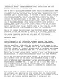
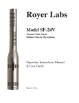
TRANSCEIVER,BOTTOMVIEW
MOBILE MOUNTING, SIDE VIEW
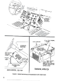
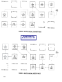
FIGURE 1. MOBILE MOUNTING ON TRANSMISSION HUMP UNDER DASH
4
TUNE-CW -Transmitting circuits are energized.
CIS02 is disconnectedfrom ground, shifting the
carrier frequencyinto the Cuterpassband.Carrier
is fully inserted. P.A. cathode resistor, R406 is
switched in the circuit, reducing input power.
Transmitteris tuned in this position. CW transmissionsmadein this position.
MIC. GAIN
Controls potentiometer R1404 in the grid of V14A,
and controls amount of audio to the balancedmodu-
lator.
R.F.GAIN
Controlsvariable resistorRS05, commonin the grids
of ReceiverMixer, V6; RF amplifier, V5; LF. Amplifiers, V7 andV8.
A.F. GAIN
Controls potentiometer R1101 in grid circuit of AF
output, VII, and controls audio volume.
MAIN TUNING
Controls C1608 in frequency determining tank circuit of VFO.
DRIVER
Controls C2A and C2B in plate tanks of transmitter
Mixer and Driver.
P.A. TUNE
Controls C407 in Pi-network to tune fmal power
amplifier plate to resonance.
P.A. LOAD
Controls C408 in Pi-network to match impedance of
output load. Tunes input to Receiver RF. Amplifier.
BAND SWITCH
Switchestank coils and associatedcapacitorsin VFO,
VFO Amplifier, Driver,and TransmitMixer.
SidebandSelectorSwitch
L5B -Receive and Transmiton Lower Sideband.
USB -Receive and Transmiton UpperSideband.
AM REC. -Receive AM signals. (Insert carrier with
CarrierInsertioncontrol to transmit.)
ANL Switch
Automatic Noise Limiter
SPOTSwitch
Insertscarrier for AM tuning in RECposition.
Meter Switch
Readscathode current in P.A. CATHODE position.
ReadsS-UNITSin S-METERposition. ReadsRELATIVE OUTPUT in S-METERposition when Function
Switchis in TUNE-CWpositi.on.
DIAL SET
Dial adjustment can be made at any 100 KHz point
with Calibratoron.
MIC
Microphoneplugsinto this jack.
CONTROL FUNCTIONS, REAR PANEL
P.A. BIAS
J. Adjustidling current for P.A. Tube. (40 ma.)
A'JX RELAY.
12 volts DC for auxiliary relaycontrol.
CW KEY
CWkey plugsinto this jack.
ANTENNA
Antenna feedline
connector.
(50
.75
ohm)
plugs
into
this
FUSEHOLDER
4 amp fuse.
EXT OSC
Model 508 or 51 OXexternal VFO connection.
HEADPHONES
Headphonesplug into this jack. Disconnectsinternal
speaker.
S-METERZERO
Adjust S-Meterto zero with antennadisconnected.
POWER
CONNECTOR
.
AC powercord plugs into this connector. Model14A
DC converterplugs in to this connector for mobile
operation.
~
;;:
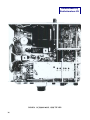
FIGURE 2. SILTRONIX MOPEL 10118, REAR VIEW.
5
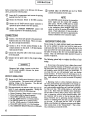
Beforeconnectingany cablesto the Siltronix lOll B transceiver,perform the following steps:
0
<D Locatethe P.A. compartmentand removethe packing
materialfrom the P.A. tube.
NOTE
CD Rotate the Function Switch to the REC. position.
0
Rotate the AF GAIN control counter clockwise to
operatethe power switch to the OFF position.
(4)
Rotate the CARRIER INSERTION control full
counterclockwiseto the minimum position.
The DRIVER control resonatesthe transmitter
driver stages and the receiver RF amplifier
plate circuit. The P.A. TUNE and P.A. LOAD
controls adjust the input and output capacitors
in the transmitter power amplifier final plate
circuit, as well as the receiverRF amplifier grid
circuit. Properadjustmentof thesecontrols in
the receiveposition will result in approximately
resonantconditions in the transmitterstages.
CONNECTIONS
-0)
Connecta wire from earthground to the groundstud
located on the rear of the chassis. This is not essential, but is stronglyrecommended.
Q)
Connect a 50 or 75 ohm antennafeed.line to the
coaxial connector on rear panel. A 50 ohm dummy
load may alsobe used.
0
Connectthe AC power cable to the Jones connector
on the rearpanel.
(9
Connect the AC power cable to the proper voltage
.source.
I
WARNING_]
Dangeroushigh voltage is presenton the plate
of the power amplifier whenever the power
supply isenergized.
RECEIVE OPERATION
CD Rotate the A.F. GAIN control clockwiseto about the
3 o'clock position. The power switch will operate,
applying voltage to the transceiver. The dial and
meterlights shouldilluminate.
@
6
Wait approximatelyone minute to allow the tube fIlaments to reach operating temperature. During this
waiting period, perform the following steps:
a. Rotate FrequencyRangeswitch to desiredrange.
b. Rotate Tuning Dial to desiredfrequency.
c. Rotate MIC. GAIN fully counterclockwise.
d. SetP.A. TUNE control to 12 o'clock position.
e. SetDRNER control to 12 o'clockposition.
f. SetP.A. LOAD control to 12 o'clockposition.
g. Rotate RF GAIN control to 3 o'clock position.
h. PlaceSIDEBAND SELECTORswitch
in USBmode.
Carefully adjust the DRIVER and the P.A. TUNE
controls for maximum receivernoise.
RECEIVER TUNING (88B)
Precisetuning of a singlesidebandsignalis very important.
Do not be satisfied to merely tune until the voice can be
understood,but take the extra careof setting the dial to the
exact spot wherethe voice soundsnatural. Above all, avoid
the habit of tuning so that the voice is pitched higher than
normal. This is an unfortunate habit practiced by quite a
numberof operators.
The following points help to explain the effects of mistuning:
1. If you tune so the receivedvoice is higherthan normal
pitch, you will then transmit off frequency,and your voice
will soundlower than normal pitch to the other station. He
will probably retune his dial to make you soun'dright. If
you keep this up, you will gradually waltz one another
acrossthe band. If both of you are mistuning to an unnatural higherpitch, you will waltz acrossthe band twice as
fast. (And someonewill no doubt be accusedof frequency
drift.)
2. Mistuning results in serioushannonic distortion on
the voice,and should be quite noticeableto the averageear.
Somewill claim that if they don't know how the otherperson'svoice actually sounds,they can't tune him in properly,
but this is not true. With a little practice, it will be fairly
easyto tell. Somevoicesare relatively rich in harmonics,
and are easierto tune in than a personwith a "flat" voice.
Also, a transmitter, which is being operatedproperly with
low distortion will be easierto tune in than one which is
being over-drivenand is generatingexcessivedistortion.
Thereis no mistaking when you havea station tuned right
on the nose. It will sound just like "AM" so to speak.
Mainly, avoid the habit of tuning so everyonesoundshigher
than normal pitch, or like "Donald Duck". This is incorrect, unnecessary,
and soundsterrible.
3. Your Siltroni.x 1011B will automatically transmit on
exactly the same frequency as the one to which you are
TRANSMITfER TUNING STEPS
listening.
CD Make the following preliminary adjustments:
a.
b.
c.
d.
e.
f.
g.
Sidebandselectorswitch in USBposition.
Tuning dial to desiredfrequency.
Mic Gain at minimum.
CarrierInsertion to full CCW(MIN) position.
Meter Switch in P.A. CATHODEposition.
Function Switch in REC position.
P.A. BIAS control on rear panel to full CCW
position.
h. Microphone with press-to-talkswitch pluggedinto
Mic Jack on front panel.
4. If it is desired to receive on lower Sideband, rotate
the SIDEBAND SELECTOR switch to the LSB position.
RECEIVER TUNING
(AM)
Refer to the RECEIVE OPERATIONparagraphabove,and
perform all the steps.
CD After adjustingthe DRIVER and the P.A. TUNE controls for maximuIJ\receiver noise, rotate the SIDE
BAND SELECTORswitch to the AM REC. mode.
@
-0
Rotate the tuning dial until an AM signal is heard.
Pl~.'?!the SPOTswitchin the ON (UP)position. This
removesthe bias from the carrier oscillator,allowing
the carrierto be heard in the receiver.
0
Zero beatthe carrier with the tuning dial.
@
Turn off the SPOTswitch.
@
The AM station should be on frequency, with excellent voice reception.
@ Pressthe Mic switch and observethe meter for any
J' reading. Meter should read approximatelyO. If the
meterdoesnot read approximately0, it indicatesthat
the CARRIER is not completelybalancedout. LOCate
the CARRIER BAL hole on the bottom cover. With
the Mic switch pressed,use an alignment tool and
adjust the carrier balancepot until the meter "dips"
at its lowest reading. This adjustmentshould not be
requiredoften.
0
Pressthe Mic Switch and with a screwdriver,adjust
the P.A. BIAS control located on the rear panel,until
the meterreadsapproximately40ma. P.A. Idling current. This point is indicated on the meter scaleby a
small triangular symbol. The permissibleidling current rangeis 30 to 50 ma. If the idling current tends
to creepupwardslightly with warm-up,set it at 30 ma.
Excessivecreepindicates that the P.A. tube is gassy,
and may need to be replacedsoon. This adjustment
should not be requiredoften.
0
If this is the first time you are tuning the .transmitter,
set DRIVER control, P.A. LOAD control, and P.A.
PLATE control to the straight up (12 0'clock) position. After gaining experiencein tuning thesecontrols, they may be pre-setto previouslydetermined
positions.
TRANSMITTERTUNING
I
CAUTIONI
READ CAREFULLY.
BE SURE THAT YOU
UNDERSTAND AND REMEMBER THESE
NOTES WHEN TUNING THE TRANSMITTER.
I. The most important detail to keepin mind whentuning the transmitter portion of your Siltronix 1011B is that
the P.A TUNE control must be resonatedas quickly as
possible.
NOTE
2. The P.A. tube is dissipatingall the power input when
it is not in resonance,and can be permanentlydamagedin
just a few seconds.
3. Onceresonancehas been established,the P.A tube
can operate at full power input for quite a while, although
we recommend30 secondsas a safemaximum. But it is
most important to realize that the 30 secondlimit assumes
that the P.A. TUNE control has been immediatelyresonated. This rule appliesgenerallyto all transmitters.
! :1
UP TO NOWTHE TRANSMITTERHAS BEEN
"IDLING" AND mERE HAS BEENNO PAR.
TICULAR TIME LIMIT INVOLVED. THE
FOLLOWING STEPS APPLY GRID DRNE,
AND REQUIRE C4UTION. OBSERVETHE
RECOMMENDED30 SECONDTIME LIMIT.
@
Set METER SWITCHto the 5-METERposition. Rotate FUNCTION SWITCHto the TUNE-CWposition
and:
4. Do not tune more often than necessary. The P.A
tube will last for many months, or even years, with normal
operation, but excessivetuning will shorten tube life.
a. Rotate DRNER control for maximum meter
reading.
.,
b. IMMEDIATELY rotate P.A. TUNE control for
maximum meter reading. -nus is the critical
"resonating" adjustment which must be done
quickly to preserveP.A tube life.
NOTE
The Transceiver will not modulate with the
Function Switch in the CAL position.
Rotate P.A. LOAD control for maximum.
AM TRANSMITTER TUNING
d. Re-adjustP.A. TUNE control for maximum. This
adjustmentshould be repeatedeachtime the P.A.
load control is adjusted.
CD Tune the transmitter to full output 3Syou would fo,r
SSB transmitter tuning.
@
Rotate MIC. GAIN control to' full CCW (minimum)
position.
0
Place the SIDEBAND SELECTORswitch in the AM
REC.position.
0
Place the Meter Switch in the P.A. CATHODE
position.
NOTE
With the Meter switch in the S-Meterposition,
and the Function Switch in the TUNE-CWposition, the meteris readingRELA TIVE OUTPUT.
This RELATNE OUTPUTreadinghas no relationship with the true output of the transmitter. To obtain a true indication of the transmitter output, place .tli.\;-lJeter switch i.. P.A
CATHODE,and rotate the Function Switchto
TUNE-CW. Normally, when the transmitter is
in resonance.the meter reading should be
approximately 300 ma. or higher. With high
line voltageand new tubes it may read as high
as 350 ma. Note that the 1011B operatesat reduced power in the TUNE-CWposition. The
P.A. cathode bias resistor,R-406, is in the circuit during TUNE and CW operation. In voice
mode, the bias resistoris shorted out, and the
1011Boperatesat full P.E.P.input rating.
@
The precedingstepscompletethe TransmitterTuning
procedure for SSB. Return the Function Switchto
the REC. position.
<D "'With the microphone press-to-talk switch pressed,
rotate the CARRIER INSERTION control until
cathodecurrent is approximately 125ma.
@
CW TRANSMI1TER
8
r""-_,.
,
TUNING/OPERATION
CD Tune the transmitter to full output as you would for
SSBtransmittertuning.
<y
Insert a CW key in the Key Jackon the rear panelof
the transceiver.
0
In CW operation, it is necessaryto switch the Function Switch to the TUNE-CW position \¥hen transmitting, and back to the REC. position while receiving.
@
While receiving, the carrier oscillator frequency is
located 300 cycles outside the passband of the crystal
lattice filter, thus providing a single heterodyne note,
or "single signal" for CW reception. When transmit.
ting in CW mode, the carrier frequency- is moved
approximately 800 cycles higher, placing it well inside the passband. This frequency shift is termed
"Off-set CW transmit frequency", and avoids the
problems encountered when the receive and transmit
frequency are exactly the same. This is desirable for
voice communication, of course, but when using the
CW Keying mode the receiver must be tuned off fre.
VOICE TRANSMISSION (SSB)
After tuning up as outlined above, switch the Function
Switch to the REC. position. Placethe Meter Switchin the
P.A Cathodeposition. Pressthe microphone press-to-talk
switch, and while speakinginto the microphone, slowly
rotate the MIC. GAIN control until occasionalpeak readings of 100 to 125 ma. are obtained. With most microphones,the MIC. GAIN control will be set between9 and
12 o'clock, but it may vary considerably. The ALC circuit
will help.limit cathode current, but turning the MIc. GAIN
up too high will still produce flat-topping and spurioussignals,so it is important to hold it down. The meteris quite
heavily damped,and its readingwith averagevoice modulation may not look very impressive,but the voicepeaksare
going well over the 260 watt input power rating of your
Siltronix transceiver.
While talking in a normal tone of voice into the
microphone,increasethe MIC. GAIN control setting
until the meter barelykicks upward. This setting will
result in excellent AM transmissions.
quency severalhundred cycles in order to hear an
audio beat. By providing this shift automatically CW
operation is greatly simplified.
GENERAL DISCUSSION
The Siltronix 1011B transceiverprovidessingle sideband,
suppressedcarrier transceiveoperation, and generatesthe
singlesidebandsignalby meansof a crystallattice filter. To
permit a logical discussionof this mode of operation, certain definitions are necessary
.
h1 a normal AM signal (double sidebandwith carrier), a
radio frequencysignalis modulatedwith anaudio frequency
signal. This is consideredby many to be merely a caseof
varying the amplitude of the carrier at an audio rate. hi
fact, however,there are actually sideoandfrequenciesgenerated, which are the resultsof mixing the RF and the A.F.
signals. Thesesidebandsare the sumof, and the difference
between,the two heterodynedsignals. In the detection()f this conventional AM signal, the two sidebandsare mixed
with the carrier to recoverand reproducethe audio intelligence. Thisis an inefficient meansof transmission,because
only 25 percentof the transmitted power is usedto transmit intelligence. Thereare other attendantdrawbacksalso.
The bandwidth of AM voice transmissionis approximately
6 KHz, while the actual demodulatedaudio is only approximately 3 KHz. The result is inefficient use of the frequency band,and overhaIf of the allotted bandis unusable
due to heterodynes,interference,and congestion..
h1 the single sideband,suppressedcarrier mode of transmission, only one of the sidebandsignalsis transmitted.
The other sidebandand the carrier are suppressedto negligible level. h1 addition to increasingthe transmissioneffi-.
ciency by a factor of four, single sideband effectively
doublesthe number of stations or channelswhich can be
usedin a givenband of frequencies.
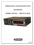
It should be rememberedthat in the single sideband,suppressedcarrier mode of transmitting, the unwanted sideband and carrier are only suppressed,not entirely eliminated. Thus, with a transmitted signal from a transmitter
with 50 db sidebandsuppression,the other or unwanted
sidebandwill be present,and will be transmitted, but its
level will be 50 db below the wanted sideband. Whenthis
signalis receivedat a level of 20 db over 59, the unwanted
sideband will be present at a level of approximately55.
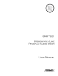
The sameis true of carrier suppression.With carriersuppressionof 60 db, and a signallevel of 20 db over 59, carrier will be present at a level of approximatelyS3 to S4.
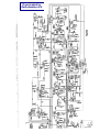
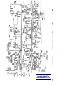
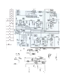
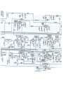
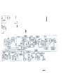
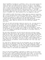
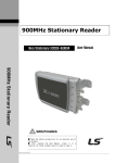
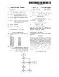
For the following discussionrefer to the schematicdia.
gram,and to Figures3, 4, and 5.
SIGNAL GENERATION
When the push-to-talk switch on the microphone is pressed,
the transmitter portion of the transceiver is activated, and it
generates a single sideband, suppressedcarrier signal in the
following manner. Carrieris generatedby Q3 CarrierOscillator, which is a Pierce oscillator with the crystal operating
in parallelresonance.This stageoperatesin both the transmit and receivemodes. Whentransmitting, the RF output
of the oscillator is injected into the control grid of the
BalancedModulator, VI3. This b'alancedmodulator is a
beam deflection tube, and operatessimilar to a cathode ray
tube in that the electronbeamfrom the cathodeis deflected
to one output plate or the other by the chargeappearingon
the deflectionplates. The carrier signalfed to the control
grid of the balancedmodulator appearson both plates of
the output. The two plates are connectedto Transformer
T130I. The deflection plate DC voltagesare adjusted by
meansof the carrierbalancecontrol, RI30S, so that the RF
beingfed to the output plates will cancelout, and the output from Tl.301 will be zero. Audio signalsfrom the Microphone Amplifier, VI4, are applied as a modulating voltage
to one deflection plate, and the two sidebandsresulting
from the sum and difference frequenciesof the audio and
carrier signalsappearin the output of transformerTI30I.
Carrier suppressionis approximately 60 db down. The
Carrier Insertion control limits the amount of carrier that
~ be insertedin AM and thus protectsthe final amplifier
from beingover driven.
The double sideband,suppressedcarrier signal is then coupled from the secondarywinding of Tl30l to the crystal
filter, which suppressesthe lower sideband,and permits
only the upper sidebandto be fed to the First IF Amplifier
V7. The carrier frequency is generatedat approximately
5500.0 KHz, nonnal sideband. With the oppositesideband
crystal, the carrier crystal frequency will be 5504.6 KHz,
and this positionsthe double sidebandsignal on the other
side of the filter responsecurve,attenuatingthe tIpper sideband by at least50 db.
Q1, the VFO 2N706 Oscillator, operatesin the common
baseconfigurationasa Colpitts oscillator. Q2, the buffer, is
used for isolation. The extremelygood regulationachieved
through using the Zenerdiode regulatorD1712 acrossthe
bias supply voltage,alsocontributesto the stability.
The VFO in the ModellOllB exmbits extremelygoodstability after the initial wann-up period. Drift from a cold
start will be less than 2 KHz during the flIst hour. After
the initial wann-upperiod, drift will be negligible.
The single sideband,suppressed
carriersignalfrom the First
I.F. Amplifier is fed to the Transmit Mixer, V2, where it is
heterodyned with the VFO signal. The resultantsignal at
the desired transmit frequency is amplified by the Driver,
V3; and the PowerAmplifier, V4. The signalfrom the VFO
Amplifier is initiated in the transistorizedVFO/Buffer circuit QI and Q2. The signalfrom the VFO is routed to the
VFO Amplifier, and is mixed with the singlesidebandfrom
the IF amplifier, resulting in output in the 10 meterband.
Whenthe transceiveris in the TRANSMIT mode, the gain
9
'.
"-.j
..,
,.
.,-,
,.,
,
I
~
I
I
V2
TRANS
MIX
12BE6
L
V4
V3
DRIVER
6GK6
POWER
AMP
6LF6
ANT
j-
~
I
V10
AGC/ALC
Q3
CAR OSC
AMP
6AV6
2N706
L_-
V7
FIRST
IFAMP
12BA6
Vl
PI NET
VFO AMP
12BA6
__I
I
V14A
MIC AMP
1/2 12AX7
V14B
AF AMP
1/212AX7
V13
BAL MOD
6JH8
I
I
XTAL
FILTER
5500 Xc
..
L ...:.:.:.
..,;;j"
FIGURE 3. BLOCK DIAGRAM, TRANSMIT MODE
Downloaded by
RadioAmateur.EU
V9A
PRODUCT
DET
1/212AX7
I
VB
I
I
SECOND
IFAMP
12BA6
L___J
L
I.
1---_J
i
ANT
~
V9B
REC
AFAMP
1/2. 12.AX7
03
CAR OSC
2N706
V7
V1
FIRST
IFAMP
12BA6
VFO AMP
PI NET
12AU6
-,
t
I
XTAL
FILTER
5500 Kc
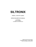
FIGURE 4. BLOCK DIAGRAM, RECEIVE MODE
10
V6
REC
MIXER
12BE6
V5
REC
RFAMP
6BZ6
of the First IF Amplifier is controlled through the Automatic uvel Control (ALC) network (using the AGC Amplifier VIO) to control the gain of the stage in response to the
average input power to the Power Amplifier. This ALC
system \vill compensate for any extremely strong input signals, but does not completely eliminate the necessity of
proper adjustment of the Mic. Gain Control. This feature
will help prevent the transmitter from flat topping and spurious emissions, but considerable distortion may occur if the
Mic. Gain Control is not properly adjusted. Refer to Operating Instructions.
TUNE AND CWOPERATION
Normally, the frequencyof the carrier oscillator is approximately 300 Hertz outside the 6 db passbandof the crystal
lattice filter. In TUNE position, the frequency of the carrier oscillatoris movedapproximately800 Hertz to placeit
well within the passbandof the crystal lattice filter. A
similar procedureis followed for CW to allow full carrier
'ootput during-cw operation.
f
CAUTION 1
CARE MUST BE EXERCISED WHEN TUNING
FOR THE 100 KHz HARMONICS OF THE
CALIBRATOR.
SEVERAL SIGNALS MAY
BE HEARD, ALTHOUGH THEY WILL BE
DEFINITELY WEAKER THAN THE COR.
RECT HARMONICS.
TRANSMIT AND RECEIVE SWITCHING
Transmit and receiveswitching is performed by relay KI.
In TRANSMIT, only those tubes that operate in the transmit mode ar~ operative,all others being biased to cutoff
through the relay contacts. In RECENE, with the relays
de-energized,the tubes that are used only in transmit are
cut off-in the samemanner. Relay Kl when de-energized,
feeds signals from the output Pj-netwcrk-+~.the receive~.
Note that relay KI will not operate when the BAND
SWITCHcontrol is in "CB" position.
RECEIVE
In RECENE position, or at allY time whenthe transmitter
is not in TRANSMIT, all circuits usedin transmitting are
disabled through the relay controlled circuits, KI. The
relay is energizedfor transmitting and de-energizedfor receiving. One contact, when de-energized,allows signals
from the transmitting tank circuit and antennato be fed to
the ReceiverR.F. Amplifier, V5; where they are amplified
and then fed to the control grid of the ReceiverMixer,V6.
The local oscillator signal from the VFO Amplifier is now
used to heterodynethe receivedsignalto the IF frequency.
All I.F. amplification is accomplishedat this frequency,
nominally 5500.0 KHz, through IF amplifiers V7 and VB.
In the Product Detector, V9A, the IF signalis heterodyned
With the carrier frequencygeneratedby Carrier Oscillator,
Q3. The resultantaudio is then amplified by V9B, which
then couplesto the AGC amplifier, VIO, and the audio output stage,VII.
POWERRATING
The Siltronix 1011B is capableof 180 watts, P.E.P.input
under steady state two-tone test conditions. The peak
envelope power, when voice modulated, is considerably
greater,typically 260 watts, or more.
Frequency calibration of the Model 10 II B is in 5 KHz in.
crements. Dial accuracy and tracking are quite good, but
caution must always be observed when operating near band
edges. Measuring the frequency with the 100 KHz cali.
brator when working near band edgesis recommended.
The built-in power supply producesa no-loadplate voltage
of approximately 880 volts. Under TUNE conditions, or
CW operation,this voltage will drop to approximately680
volts. Under steadystatetwo-tone modulation, the voltage
will drop to approximately710 volts. If the power amplifier idling current is 40 ma.,'and the two-tone current, just
before flat-topping, is 200 ma., the peaktwo-ton. current
will be 300 ma. Under theseconditions, the P.E.P. input
will be 710 volts times 300 ma..= 213 watts. Undervoice
modulation, becauseaveragepower is considerablyless,the
power amplifier plate and screenvoltageswill be maintained
higher, evenduring voice peaks,by the power supply filter
capacitors. Peakplate current will thereforealso be higher
thanwith two-tone test conditions. Under typical operating
conditions, peak plate current before flat-topping will be
350 ma. at 800 volts, to result in an input of 280 watts
P.E.P. Readingsof cathode current will not reflect this
power input, however,becauseof the dampingin the cathode current meter. Cathodecurrent readingsunder normal
voice input should not averagemore than 100 to 120 ma.
DIAL SET
POWER AMPLIFIER PLATE DISSIPATION
A DIAL SETcontrol has beenprovided so that dial adjustment can be made at any 100KHz point on the dial. With
calibrator on, set the dial to any loa KHz point closestto
the frequency you wish to work. Now adjust DIAL SET
control to zero-beatthe VFO with the 100KHz Calibrator.
This providesgreateraccuracyof dial readout.
There is often a misunderstandingabout the plate dissipation of tubesoperatedas ABI amplifiers undervoice modulation. In the Siltronix 1011B, while in the transmit mode,
and with no modulation, the plate voltage will be approximately 830 volts, the plate current 40 ma., and the power
input 33 watts.
FREQUENCYCALIBRATION
~
-,iIt-i
;'1t-
Authorities agreethat the averagevoice power is 20 to 20db
below peakvoice power. Normally, some peak clipping in
the power amplifier can be tolerated,and a peak-to-average
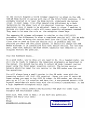
ratio of only 6 db may sometimesoccur. Under suchconditions, the averagepower input will be 80 watts,and averageplate current will be 100ma. With power amplifier efficiency of 65 percent,plate dissipationwill be approximately
5498
SSOO
26 watts. The 6LF6 is rated at 40 watts,continuous duty
cycle, in normal TV service. "n1US
it canbe seenthat under
normal operating conditions, the Power Amplifier tube in
the 101lB is not being drivenvery hard. Note, however,that
proper modulation level must be maintained by correct set.
ting of Mic. Gain,and that the length of time in TUNE position mustbe limited to not more than 30 secondsat a time.
SSOZ
SS~ KC
55)4
0 608-
-
-
ZOOS
-
-
-
40DB-
-
60 DB.
-
-
80 DB-
iT
I
0--.
100D8-J-~--fIE-
IZ KC
-
-
FIGURE 5. CRYSTAL FILTER CHARACTERISTICS
12
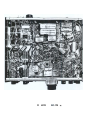
Dle alignment procedures presented in this section are routine touch-up procedures for all tuned circuits and other
adjustments. It is recommended that the procedures be
performed in the order presented. However, if complete
realignment is not required (as may be the case when just
one tube is replaced), perform just those procedures required. Refer to Figures 6 and 7 for component placement.
2. The alignmentof transmittercircuits involvesthe adjustment of tuned circuits in the VFO Amplifier, VI; the
Transmit MIXER, V2; and the DRIVER stage,V3. It is
recommendedthat a 50 ohm dummy load be connected
to the antennajack during this seriesof adjustments.
CD Set the tuning dial to approximately ~8.3 MHz,
and the DRNERcontrol at 12 o'clock.
RECEIVER AliGNMENT
@
SetP.A. LOAD control to 9 0'clock.
Receiver alignment involves only the adjustment of the
SecondI.F. coil. The R.F. coils which affect receiverperformanceare also used in the TRANSMITmode. Theiradjustment iscoveredunder"TRANSMITTERAUGNMENT".
0
SetMETER switch to P.A. CATHODE.
@
PressMic. button. Checkidling CUlTent.It should
be on the "delta" symbol when the CARRIER
BALANCE control is nulled, and the CARRIER
INSERTION control is fully counter clockwise.
Adjust P.A. BIAS control if necessary.
~.
Q)
After allowing approximatelyfive ~i"utes for warmup, tune the receiverto the middle of the bandand on
a "clear" frequency.
0
Adjust the P.A. TUNE, P.A. LOAD, AND DRIVER
controls for maximumnoise.
CD Adj~st the Second I.F. coil (LB01) for maximum
backgroundnoise.
S-METER ADJUSTMENT
With the antenna disconnected,R.F. GAIN control fully
clockwise, and METER switch in S-METERposition, set
R70S, located on the rear panel, for zero meter reading.
Makesureno local signalsare beingreceived.
TRANSMITTER ALIGNMENT
0
With Mic. button pressed,adjust CARRIER BALANCE control for slight increasein meter reading,
50 to 60 ma. Adjust P.A. TUNE c{Jntrolto resonance(dip).
CD Adjust coils LI0l, L201,and 1301, for maximum
reading. Whenreadinggoeshigher than 80 ma., or
so, adjust CARRIER BALANCE control for 60
ma. again.
@
Adjust coils carefully for maximumpeak. Exercise
caution with CARRIER BALANCE control. Do
not exceed 100 ma. reading for more than a few
seconds. Be sureP.A. TUNE control is resonated
(adjustedfor "dip" in meterreading).
3. PowerAmplifier Neutralization.
To adjust the Power Amplifier Bias:
0
After allowing approximatelyfive minutes for
warm-up, tune transmitter to approximately 283
Switch METER switch to P.A. CATHODE posi-
MHz.
tion.
Rotate CARRIER INSERTION
counter clockwise. .
control
@
Setthe P.A. LOAD control to 9 o'clock.
@
SetMETER switch to P.A. CATHODE.
0"
Key the transmitter with the Mic. button, and
without speakinginto the microphone,adjust the
CARRIER BALANCE control for a reading of
approximately 100 ma.
Quickly adjust the
DRNER control for a peak. Quickly re-adjustthe
CARRIER BALANCE control to 100 ma. if it increasedto a higherreading.
0
With the Mic. button still pressed,rotate the P.A.
TUNE control through its rangefrom 9 o'clock to
3 o'clock. You will note a pronounced "dip" in
meter readingat resonance.Observeany tendency
fully
After allowing approximately five minutes for
warm-up, key the transmitter with the microphone
switch. Without speaking into the microphone, adjust the Carrier Balance control on the bottom
cover for a Null.
Again key the transmitter with the microphone
switch,and without speakinginto the microphone,
adjust the P.A. BIAS control on the rear panel
until the meter reads 40 ma. of idling current.
This point is indicatedon the meterby the "delta"
symbol.
]3
:'t
,',','
",'"
-'~-".-
Downloaded by
RadioAmateur.EU
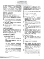
FIGURE 6. SILTRONIX MODEL 10118 TOP VIEW.
14
for the meter to "peak" abovethe 100ma. plateau
on either side of resonance.If there is sucha peak,
adjust C40l, the P.A NEUTRALIZING trimmer
to suppressthe peak. Whenproperly neutralized,
the meter reading will hold steadily at 100 ma.
except for the sharp dip at resonance,but there
will be no peakabovethe 100ma. level.
0
Increasegain of audio generator until the wattmeter reads40 watts. Sweepgeneratordown to
200 Hertz and adjust the USB carrier oscillator
trimmer, C1S03,for a readingof 10watts.
CD Switch to the LSB position. Adjust the LSB carrier oscillator trimmer, C1S0l, for a reading of
10 watts.
<D Key the transmitter with the Mic. button, and readjust the CARRIER BALANCE control for mini.
mum Power Amplifier current. Power Amplifier
idling current shouldbe on the "delta" symbol. If
not, repeatthe Power Amplifier Bias adjustment
described in TRANSMITTER AUGNMENT,
STEP1.
4. CarrierFrequencyAdjustment.
A dummy load wattmeter and audio generatorare reo
quired for this adjustment.
-~-~..
0
After
.~..'-allowing a five minute warm-upperiod,tune
the transmitterto approxjmatley28.3 MHz.
@
Key the transmitter with the Mic. button, and
adjust the CARRIER BALANCE control for minimum power amplifier current.
0
Insert 1500 Hertz of audio from an audio generator into the Mic. Jack on the front panel. Adjust
the gain of the audio generatorand the Mic GAIN
control (R1404) until the wattmeterreadsapproximately 10 to 15 watts.
@
16
Adjust the First I.F. coil, L701, for maximumoutput. Adjust both slugsof the balancedmodulator
transformer,T1301, for maximumoutput.
@
Re-checkwith audio generator set at 1500 Hertz
and 40 watts. Sweepdown to 200 Hertz and readjust carrier oscillator trimmers, if required, for
10 watts.
S. VFO Calibration.
Mter allowing approxjmatelyfive minutes for warm-up,
tune the dial to the 200 KHz increment for any of the
10 meter rangesto be calibrated. For CB calibration,
tune the dial to the 27,100 KHz increment. Using the
~100 KHz crystal calibrator as a signalsource,tune the
signalfor zero beatand note the cor!espon~~'!g-dial
read.
ing. If the signaldoes not zero beat on the desireddial
increment,locate the VFO coverand carefully adjustthe
correct trimmer until it does.
Use an insulated alignment tool for adjustment. Accuracy in other parts of the bands will be quite good,but
rememberthat the 1011B is not to be considereda frequencystandard;Be cautious when operatingnearband
edges.
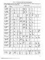
6. Troubleshooting.
The information contained in Figures6 and 7, together
with the voltageand resistancemeasurements
in Table 1,
and the information in Table 2, should be sufficient for
most troubleshooting by the averagelicensed amateur
radio operator.
,
TABLE 1. VOLTAGE AND RESISTANCE MEASUREMENTS
Voltage measurements were taken using a HEWLETT
taken using a SIMPSON MOdel 260 Volt-Ohm meter.
TUBE
TYPE
R = Rec.
T = Trans.
VI 12BA6
R Volts
T Volts
Ohms
VFOAmp.
Driver
V5 6BZ6
Rec.RF.
Model 410C/B VTVM.
1
2
3
1.2K
12.6AC 45
12.6AC 50
0
0
0.2
0
-1.2
-1.0
0
0
12.6AC
12.6AC
250
-2
250
135
lOOK
0
0
0
0
.02
R Volts
T Volts
Ohms
0
0
-6.7
-6.7
lOOK
0
0
0
63AC
63AC
10
0
0
0
RVolts
T Volts
0
0
0
6.3AC
0
0
0
6.3AC
0.1
0
0
12.6AC
I
12.6AC
220
110
12.6AC
12.6AC
220
0
0
0
20K
20K
12.6AC
~._!..:tM
R Volts
Rec.Mixer
T Volts
-3.7
-3.4
Ohms
200K
0
0
0
V7 12BA6
RVolts
1stI.F.
-1.8
-1.8
500
0
0
0
0
T Volts
Ohms
0
0.1
-1.7
-1.7
0
110K
0
0
0
VB. 12BA6
RVolts
2ndI.F.
T Volts
Ohms
V9 12AX7
Via 6AU6
AGCAmp.
.
03
255
255
14K
115
0
0
40K
0
145
-.25
-.25
0
0
6.3AC
0
0
125K
1M
0
0.2
0
225
175
0
20
0
50OK
1.6
6.3AC
6.3AC
0
0
0
0
5K
0.2
0
0
0
700K
215
0
10K
6.3AC
63 AC
63 AC
250
250
RVolts
0
0
TVolts
45
Ohms
2K
45
.75K
50
45
1M
0
0
0
1
2
3
0
NC
NC
NC
V14 12AX7 R Volts
T Volts
Ohms
R Volts
T Volts
Ohms
12.6AC
12.6AC
0
0
2.4
6.3AC
0
12.6AC 225
12.6AC 175
0.1
lOOK
V13 6JH8
0
75
~
0
0
0
70K
0
R Volts
T Volts
Ohms
Bal.Mod.
0
0
0
300
1M
0
105
0
40K
IlK
0
0
12.6AC 205
12.6AC 225
lSK
0.1
400K
0
0
0
0.2
lSK
0
0
0
0
0
0
50
50K
0
V12 12BA6 R Volts
100KCCal. T Volts
Ohms
*
0
225
48
1
0
22
0
255
265
-1.6
1.9
0
I
NC
NC
NC
-1
0
10K
0
35K
55
.7
9
210
220
12.6AC
0
8
g
IlK
-3
0
V46LF6
Pwr. Amp.
.
R Volts
T Volts
Ohms
VII
R Volts
A.F. Output T Volts
Ohms
Mic. Amp
45
50
0
0
7
6
0
0
V612B£6
Det.AF.
s
4
0
0
O~
Resistance measurements were
SocketPin Numbers
-.6
-.6
V2 12BE6 RVolts
Trans.Mixer T Volts
Ohms
V3 6GK6
PACKARD
6.3AC
6.3AC
0.2
0
0
0
0
0
0
lOOK
9
0
0
0
170
0
2.5K
1.IM
120K
0
8K
225
175
200K
75
55
0
0
-1.4
0
0
0
-1_~~
l
0
0
100
75K
75K
0
0
6.3AC
6.3AC
0
0
~
0
0
0
0
0
0
75
0
0
600KI
0
0
4
0
0
0
6.3AC
6,7,8.9
5
-75
-75
180K
I
NCI
NC
,
NC
~
10
10K
100
0.2
12
11
0
0
0
0
180
12.6AC
12.6AC
100
0
I
17
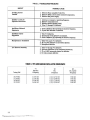
TABLE 2. TROUBLESHOOTING GUIDE
DEFECT
POSSIBLECAUSE
PA Idling Current
Unstable
1. DefectivePowerAmplifier Tube(V4).
2. DefectiveBIAS control and/or associatedcomponents.
3. Defectivebias powersupply.
Inability to Load per
OperationInstructions
1.
2
3.
4.
Insufficient Sideband
Suppression
1. CarrierOscillator(Q3) operatingon incorrect frequency.
2. Crystal fllter defectiveor mistuned.
Insufficient Carrier
Suppression
1. TubeV13 defective.
2. TransformerT1301 defectiveor mistuned.
3. Oirrier O~i11ator(Q3) operatingon incorrectfrequency.
Microphonicsin Transmitter
r:'I'iibes V13 and/or V14 defective.
2. IF coil 1701 Defective or incorrectly adjusted.
Antennanot resonantat operatingfrequency.
Defectivetransmissionline.
Defectiveantennaloadingcoi1(s).
TubesVI through V4 defective.
3. Microphone
defective.
Low Receiver Sensitivity
1.
2.
3.
4.
TubesVS through VIO defective.
mcorrectadjustmentof the transmitterPi-Network.
IF coil L80I incorrectly adjustedor defective.
Kl relay contactsdefective.
TABLE 3. VFO AND CARRIER OSCILLATOR FREQUENCIES
18
~--.
~
~--- -.
[PARTS
RESISTORS
RlOO6
RlOO7
All resistorsare 1,2watt 10%
tolerance,unlessotherwisenoted.
RlOl
82 Ohm
Rl02
47K
Rl03
10K.2W
Rl04
56 Ohm
R20l
27K
R202
lOOK
R203
lOOK
RII05
R1201
R204
10K.2W
R1202
470K
2.7K
lOOK
lOOK
10 Ohm
100Ohm
100 Ohm
25K BiasPot.
4.7K
IK
3 Ohm-5W
100 Ohm-SW
2.7K
l5K
lOOK
220K
470 Ohm
10K
25K R.F. GainPot
10K
470K
47K
1.5K
33K-2W
lK
R1203
R1301
R205
R206
R30l
R302
-R303 .,
R304
R40l
R402
R403
R404
R405
R406
R407
R408
RSOI
RSO2
RS03
RS04
RS05
RS06
RS07
R601
R701
R702
R703
RlOO8
RIOO9
RlIOl
RII02
RII03
R1104
R1302
R1303
R1304
R1305
R1306
R1307
R1308
LIST I
R1710
R1711
2.2 Meg
270K
2.2 Meg
lOOK
TRANSISTORS
1 Meg A.F. Gain Pot
lOK
lOOK
1 Meg
270 Olun
1 Meg
27K
lOOK
lK
10K
lOK
,.
270K
.,
R1403
R1404
1 Meg Mic. Gain Pot
R140S
R1406
270K
470K
2.2 Meg
47K
lOK
68K.2W
22K
2.2K
l.5K
lOOOlun
2.7K
R1311
R1312
R1313
R1401
Rl402
R1407
R1408
R1501
R1502
R1503
R1504
R704
47K
R705
R706
R707
R708
25K 8-MeterZero Pot
l5K
47K.2W
lOOK
R801
lOOK
R1602
R1603
R802
IK
R1604
R803
4.7K
R160S
R901
R902
lOOK
270 Ohm
R903
270K
R904
R905
R906
R907
R908
RlOOI
RIO02
RlOO3
Rl 004
RlOO5
47K
lO Meg
1 Meg
47K
lOOK
1 Meg
270K
470K
4.7K
l5K
R1606
R1607
R1608
R1609
R150S
R1506
R1601
R1701
R1702
Rl703
R1704
R170S
R1706
R1707
R1708
R1709
Ql
Q2
Q3
2,N706Oscillator
2N5130 Buffer
2N706 Car. Oscillator
DIODES
lOK.l W
27K
27K
SK Car.Bal. Pot
lK
lOOK
27K
SelectedValue
5K Carrier InsertionPot
l50K
47K
lK
R1309
R1310
500 Ohm-lOW
lOOK
l.5K
lK
lOOK
470 Olun
2.7K
lK
470 Olun
470 Olun
lOK.2W
4.7 Ohm
l50K.2W
lSOK.2W
800
Ohm-lOW
l.2K-5W
.
270K
2.7K
800 Ohm-lOW
D401
IN34A
DSOI
IN914
D701
IN914
D702
IN914
D703
IN914
D901
IN34A
."-.~DIOOIIN914'.DIOO2
IN34A
DlOO3
IN34A
D1201
IN34A
D1601
IN914
D1701
RCA 39804
D1702
lA-600V
D1703.1706 RCA39804
D1707.1710 RCA 39804
D1711
RCA 39804
D1712
IN4742 Zener
COILS
LI0l
UOI
1.301
1.302
IAOI
IA02
IA03
VFO Amp
Trans.Mixer
Driver
82uh
L1701
82uh
55uh
Pi-Network
30uh
5500KC I.F.
5500KC I.F.
200 uh
VFO Coil
200 uh
200 uh
200 uh
L1702
17uh
IA04
L701
1.801
LIS0l
L1601
L1602
Ll603
CAPACITORS
Unless otherwise specified, a capacitor
is listed in pico farads with a whole
number and in micro farads with a
decimal num ber .
CIOI
.01 +80-20% 500V Disc
CI02
.00220% lKV Disc
CI03
27pf Disc
CI04
1 pf 500V Ceramic
CI05
15pfDisc
CI06
5pfDisc
CI07
2pfDisc
19
CI08
C302
C303
C304
2pf Disc
2pf Disc
.01 +80-20% 500V Disc
.002 20% 1 KV Disc
.05 200V Mylar
.01 +80-20% 500V Disc
470pf SM
2pf SOOVCeramic
.00220% lKV Disc
20pf Driver Tuning
20pf Driver Tuning
.00220% lKV Disc
51OpfSM
.00220% lKV Disc
C305
5pf
.CI09
ClIO
C111
.C201
C202
C203
"
C204
C205
C2A
, C2B
C401
C402
C403
C404
C40S
C4Q6
..~.C407
.
C408
C409
C410
C501
C502
C503
C601
C602
C603
C701
C702
C703
C704
C70S
C706
C801
C802
C803
C804
C80S
C901
C902
C903
C904
C905
C906
CI001
C1002
CI003
CI004
Cl005
CI006
CI007
CII01
C1102
C1103
C1104
C1201
C1202
C1203
2Opf Neut. Trimmer
15pf3KV Disc
.01 +80-20% 500V Disc
.002 20% 1 KV Disc
.01 +80-20% 500V Disc
27Opf 2500V Mica
--40pE.l!rA. Tune
41OpfP.A. Load
.01 +80-20% 500V Disc
.01 +80-20% 500V Disc
.01 +80-20% 500V Disc
.01 +80-20% 500V Disc
3Opf Disc
.01 +80-20% 500V Disc
220pf Disc
43Opf SM
1 MFD 50V
5Opf Disc
.01 +80-20% 500V Disc
.01 +80-20% 500V Disc
2pf Disc
.01 +80-20% 500V Disc
.01 +80-20% 500V Disc
.01 +80-20% 500V Disc
.01 +80-20% 500V Disc
5Opf Disc
5Opf Disc
220pf Disc
.00220% IKV Disc
ISO pf Disc
2 MFD 450V
50Opf Disc
.00220% lKV Disc
.05 200V Mylar
.05 200V Mylar
.001 20% Disc
.01 +80-20% SOOVDisc
.001 20% Disc
.001 20% Disc
.001 20% Disc
220pf Disc
.002 20% I KV Disc
.01 +80-20% 500V Disc
.01 +80-20% 500V Disc
.01 +80-20% 500V Disc
.01 +80-20% 500V Disc
.01 +80-20% 500V Disc
220pf Disc
.002 20% 1 KV Disc
.01 +80-20% 500V Disc
.1 10% 400V Mylar
.01 +80-20% 500V Disc
.01 +80-20% 500V Disc
.110%400VMylar
10Opf Disc
.01 +80-20% 500V Disc
6-3Opf Ceramic Trimmer
10pfDisc
6-3Opf Ceramic Trimmer
27Opf SM
270pf SM
.01 +80-20% 500V Disc
30pf
J.
Selected
5pf Trimmer
5pf Trimmer
5pf Trimmer
Selected
5pf Trimmer
5pf Trimmer
10pfMain Tuning
Selected
2pf Dial Set
20pf Disc
27OpfSM
6-30pf Ceramic Trimmer
.01 +80-20% 500V Disc
.01 +80-20% 500V Disc
30OpfSM
27pf SM
.01 +80-20% 500V Disc
.01 +80-20% 500V Disc
.00220% lKV Disc
.01 01.80-20%500V Disc
100 MFD 35V
.01 +80-20% 500V Disc
.00471KV
.0047 lKV
150 MFD 150V
100 MFD 350V
100 MFD 350V
.00220% lKV Disc
.01 +80-20% 500V Disc
80 MFD 400V
80 MFD 400V
5 MFD 400V
5 MFD 400V
150 MFD 150V
150 MFD 150V
500pfDisc
.01 10% 1 OOOVTubular
50pf Disc
6Opf Trimmer
I 5Opf Disc
20
~;-;;:.-.;-=::-::.-
C1301
C1302
C1303
C1304
C1305
C1306
C1307
C1401
C1402
C1403
C1404
C1405
C1406
C1407
C1501
C1502
C1503
C1504
C1505
C1506
C1507
C1601
C1602
C1603
C1604
C1605
C1606
C1607
C1608
C1609
C1610
C1611
C1612
C1613
C1614
C1615
C1616
C1617
C1618
C1619
C1620
C1701
C1702
C1703
C170S
C1706
C1707
C1708
C1709
C1710
C1711
C1712A
C1712B
C1712C
C1712D
C1713
C1714
'
,..
';..,.-.
TRANSFORMERS
TII01
T1301
T1701
A.F. Output Trans.
5500KC Bal.Mod. Trans.
PowerTrans.
2401
ParasiticSuppressor
RELAYS
Kl
3 PDT Relay, 12 VDC Coil
CRYSTALS
YI20I
YI50I
YI502
IOOKCCrystal Calibrator
5500KC CarrierOscillator
5504.6KC CarrierOscillator
TUBES
VI
V2
V3
V4
VS
V6
V7
V8
V9
VIO
VII
VI2
VI3
VI4
12BA6 VFO Amp.
12BE6Trans.Mixer
6GK6 Driver
6LF6 PowerAmp.
6BZ6 Rec. RF Amp.
12BE6Rec. Mixer
12BA6 First I.F. Amp.
12BA6 SecondI.F. Amp.
12AX7 Prod. Det/Rec.Audio
6AV6 AGC/ALC Amp.
6GW8A.F.l::>1:itput
~
12BA6 100KC Cal.
6JH8Bal. Mod.
12AX7 TransA.F./Mic. Amp.
SWITCHES
SIA-B
S2
53
54
Bandswitch
PowerOff and On
(part of RF Gain)
Cal. Rec. Tune/CW
P.A. Cath./S-Meter
55
ANL
56
SidebandSelector
S7
Spot
Downloaded by
RadioAmateur.EU
WARRANTY POliCY
Silt."On~ Corporation walTants this equipment against
def~ts in material or workmanship,except for tubes,
transistors,and diodes. under nolmal servicefor a period
of 6 months from date of original purchase: Tubes,transist~rs,and diodes are coveredunder the warranty policy
for Ii period of 90 days. This warranty is valid only if the
enclosedcard is properly filled in and mailed to thefactory
within ten days of date of purchase. Do not ship to the
factory without prior authorization. This warranty is
IOn/ted to repairingor replacingonly the defectiv.eparts,
and is not valid if the equipmenthas been tampered with,
misusedor damaged. A 11returnsfor repairsmust be sent
freight prepaid. Siltro,nix will prepay the return freight.
~..- ...~.-.
".
'-:.
.,;
I
.-1
'I..
..
~~-..~..".,~"..~'-:-..,..,"-.,.-;
.
.'.
--;"'-"
-'.
,.
.,
~
-_A:-
-
Downloaded by
RadioAmateur.EU
Downloaded by
RadioAmateur.EU
~
~
T.-
"1~~~~~~.~J.
-
RCA-
.,
-
-.
---
---'"\..1-
.-J
mc~
WF
2Mr
~I. ~I'I
0
0
i i...-
0
Dl111
I"
cms
_~I'
K
-I-
..
~
,"'-
I
I
,
~I
I
I
I
I
I
I
I
.I
I
.I
I
I
_I
~
':"
:-J
:...
Il
11
-
--1Z/»
Downloaded by
RadioAmateur.EU