1
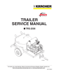
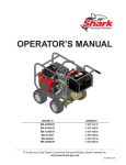
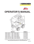
® SERVICE MANUAL TR INS UC NS TIO T EN D Y EM AN GVERTISS YSE INJUR LLE N/A PU US NIN D CA AR CIO SECAN WPRECAUEXPO LTS BE INS UC TR INS TR TIO UC CIO NE S NS R ON NdE pRE I O f Of ° 40 40 pREON NdE O R pO ° ° 25 wER ° 15 COR COURIE NTE RAN T er watt hotutle O hE AT ER CAL ChA ENT UffAdO E-E R AU I Of ApA f ETT gAR EIN T hE AT ONER CON TRO LAd TIM ER OR MIN dE UTE — ater dw ColInlet 7 dA Y 7 dE TIE RIE MpO dE JOU SIE RS TE dIE AS ExT pU RAI LL OU TIRgA LAS T ER LES CLApIN pOI VIJAS TO NTE S pARSE LESURS A T dE hORVER EST SIR AbL AIR S L’E ECEEd ES xTE d’O RIER EL“ON” pER UR TIE TIM ATI pOU MpO ES ON . R E’TAdES bLIEAd R O. 10-0 726 98009660-1 MODEL # HDS 4.0/20 E Ec / EEC-422007C ORDER # 1.109-075.0 HDS 4.0/30 E Ec / EEC-353007C 1.109-076.0 To locate your local Kärcher Shark Commercial Pressure Washer Dealer nearest you, visit www.karchercommercial.com or www.karchershark.com 9.800-966.0 CONTENTS Exploded View 4-5 Exploded View Parts List 6-7 Cabinet Exploded View 8-9 Cabinet Parts List 10 Hose and Spray Gun Assembly 11 Specifications 12-13 Unloader Adjustment Procedure 13 VBR & VB8 Unloader Valve Exploded View & Parts List 14-15 KM Series Exploded View & Parts List 16-17 Troubleshooting 18-20 Wiring Diagrams 21-22 Model Number ______________________________ Serial Number ______________________________ Date of Purchase ___________________________ The model and serial numbers will be found on a decal attached to the pressure washer. You should record both serial number and date of purchase and keep in a safe place for future reference. 9.800-966.0 • KÄRCHER SHARK • Rev. 6/09 OPERATOR’S MANUAL PRESSURE WASHER Exploded View - Left Side 17 84 86 8 Reversed View of Electrical Panel Components 89 4 10 Time Delay Option 87 95 93 84 92 5 84 57 56 25 6 3 26 1 92 59, 94 9 75 49 19 82 20 64 2 21 82 16 62 23 82 18 22 24 15 24 98 49 26 1 97 65 Time Delay Option 96 9.800-966.0 • KÄRCHER SHARK • Rev. 6/09 98009660-2 7 PRESSURE WASHER OPERATOR’S MANUAL Exploded View - Right Side 11 14 28 66 83 13 56 12 59 60 43 88 54 47 45 50 99 48 44 46 73 80 74 70 68 58 77 27 36 61 80 30 38 29 40 41 39 32 33 50 63 91 79 90 67 52 42 69 31 81 34 37 90 35 78 55 20 51 85 80 53 72 71 50 15 98009660-3 9.800-966.0 • KÄRCHER SHARK • Rev. 6/09 OPERATOR’S MANUAL PRESSURE WASHER Exploded View Parts List ITEMPART NO.DESCRIPTION 1 9.802-362.0 8.715-483.0 Unloader, PA 8GPM@3650 PSI, VB8 W/Switch 1 Unloader, AL (VRT607) (Time Delay Option) 1 2 Pump, See Specification Pages 3 Motor, See Specification Pages 4 Overload, See Specification Pages 5 Transformer, See Specification Pages 6 Fuse, See Specification Pages 7 Fuse, See Specification Page 28-29 8 Contactor, See Specification Pages 9 9.802-259.0 Hose, 1/2" Push On 18" 10 9.802-457.0 Din Rail, 35mm 4" (Time Delay Option) ITEMPART NO.DESCRIPTION QTY 35 8.706-998.0 Connector, 3/8" Anchor 1 36 9.804-058.0 Bolt, Pump Mounting 4 37 9.802-039.0 Elbow, 1/2" JIC x 3/8" 90° MPT 1 38 8.712-345.0 Nozzle, SAQCMEG 0004 Red (HDS 4.0/30) 1 8.712-361.0 Nozzle, SAQCMEG 0006 Red (HDS 4.0/20) 1 39 8.712-346.0 Nozzle, SAQCMEG 1504 Yellow (HDS 4.0/30) 1 8.712-362.0 Nozzle, SAQCMEG 1506 Yellow (HDS 4.0/20) 1 6" 40 8.712-347.0 Nozzle, SAQCMEG 2504 Green (HDS 4.0/30) 1 8.712-363.0 Nozzle, SAQCMEG 2506 Green (HDS 4.0/20) 1 11 9.802-476.0 Box, Plastic, 10" x 8" x 6" w/Lid 1 12 9.803-038.0 Bracket, Support for Elec Box 1 13 9.802-518.0 Strain Relief, 3/4" LQ Tite 1 9.802-526.0 Locknut, 3/4" 1 14 9.802-515.0 Strain Relief, Strt, LQ Tite, Med 1 42 9.800-064.0 Label Karcher Control Panel CT1 9.802-524.0 Locknut, 1/2" Conduit 1 43 8.932-985.0 Label Karcher Stripe 17" 15 9.802-240.0 Hose, 3/8" x 22", 2 Wire, Pressure Loop 44 Bushing, See Specification Pages 1 45 Bushing, See Specification Pages 16 1 46 Pulley, See Specification Pages 47 Pulley, See Specification Pages 48 Belt, See Specification Pages 49 9.802-048.0 Swivel, 1/2" JIC Fem, 3/8" Male1 50 9.802-765.0 Screw, 1/4"x1/2" BH SOC ES 14 51 9.802-817.0 Washer, 3/8" x 1" Steel 4 52 9.802-283.0 Hour Meter, 115 VAC 1 53 9.802-720.0 Bolt, 3/8" x 1", NC HH 4 QTY 9.803-670.0 Pump Protector, 1/2, 190° 41 8.712-348.0 Nozzle, SAQCMEG 4004, White (HDS 4.0/30) 1 8.712-364.0 Nozzle, SAQCMEG 4006, White (HDS 4.0/20) 1 2 17 9.802-473.0 Timer, Multi-Function (Time Delay Option) 1 18 9.802-039.0 Elbow, 1/2" JIC, 3/8", 90° 1 19 9.802-779.0 Nut, 3/8" ESNA 4 20 9.802-807.0 Washer, 3/8", SAE, Flat 8 21 8.706-797.0 Nipple, 1/2" Hex 1 22 8.706-844.0 Tee, 1/2" Female, Pipe 1 23 9.802-128.0 Nipple, 1/2" JIC x 1/2" MPT Pipe1 24 9.802-131.0 Elbow, 1/2" JIC x 1/2", 90° 2 54 8.932-965.0 Label, Warning, Exposed Pulley 1 25 9.802-039.0 Elbow, 1/2" JIC x 3/8" Steel 1 55 8.932-970.0 Label, Cold Water Outlet 1 26 9.802-129.0 Elbow, 1/2" x JIC x 3/8", Brass 1 56 9.802-429.0 Service Cord 12/4 27 9.802-807.0 Washer, 3/8 Flat 4 57 8.932-969.0 Label, GFCI 28 9.802-879.0 Cover, Kärcher 1 58 9.802-522.0 Strain Relief 1" 29 9.802-875.0 Base, Kärcher 1 59 9.802-429.0 Service Cord 12/4 30 9.802-451.0 Switch, Rocker, Carling w/Green Lens 1 60 9.802-518.0 Strain Relief, Strt, LQ Tite 3234 Large 1 9.802-452.0 Switch, Rocker, Red Face (Time Delay Only) 1 31 4 9.802-066.0 Pad, Soft Rubber, 50 Duro 32 9.802-064.0 Grommet, Rubber, Nozzle Holder 4 33 9.802-146.0 Swivel, 1/2" MP x 3/4" GHF w/Strainer 1 34 1 8.707-000.0 Connector, 1/2" Anchor 10 ft. 1 1 40" 9.802-526.0 Locknut, 3/4" 1 61 9.800-013.0 Label, Intended For Indoor Use 1 62 9.802-259.0 Hose, 1/2" Push-on 12" 63 9.802-779.0 Nut, 3/8" ESNA NC 4 64 8.706-207.0 Elbow, 3/8" Street 1 65 8.716-125.0 Switch, Pressure (Time Delay Option) 1 66 9.802-514.0 Strain Relief, 1/2" 1 9.802-524.0 Locknut, 1/2" 1 9.800-966.0 • KÄRCHER SHARK • Rev. 6/09 ITEMPART NO.DESCRIPTION QTY 67 9.803-081.0 Cover, Access Hole 1 68 8.901-148.0 Label, Caution 1 69 9.800-020.0 Label, Cold Water Inlet 1 70 8.718-980.0 Washer, 5/16" Flat 4 71 9.802-738.0 Bolt, 1/2" x 8" NC HH 1 72 9.802-800.0 Washer, 1/2" Flat 1 73 9.803-100.0 Slider, Pump 1 74 9.802-776.0 Nut, 5/16" ESNA 4 75 9.802-042.0 Elbow, 1/2" JIC x 3/8" Female, 90 DGR 1 76 8.706-294.0 Bushing, 1/2" x 3/8" Steel 1 77 9.800-034.0 Clear Lexan 1 78 8.901-136.0 Detergent label 1 79 9.802-067.0 Bumper Pad 4 80 9.802-073.0 Weather Stripping 7 ft. 81 9.802-074.0 Nut, 1/4" Square 4 82 9.802-151.0 Swivel, 1/2" JIC Fem. Push-On 4 83 9.802-424.0 Cord, 16-4 Service 84 9.802-695.0 Nut, 10/32" Keps 85 9.802-723.0 Bolt, 3/8" x 1-1/2" NC HH 4 86 9.802-759.0 Screw, 10/32" x 1/2" Black 10 87 9.802-762.0 Screw, 10/32" x 1-1/4" 1 88 9.802-773.0 Nut, 1/4" ESNA NC 2 89 9.802-791.0 Cage Nut, 10/32" x 16 Gauge 6 90 9.802-794.0 Cage Nut, 1/4" x 12 Gauge 8 91 9.802-811.0 Washer, 3/8" x 1-1/2" Fender 4 92 9.800-040.0 Label, Ground 2 93 9.803-302.0 Standoff, Electrical Box 1 94 9.802-520.0 Strain Relief, 3/4" 1 PRESSURE WASHER OPERATOR’S MANUAL Exploded View Parts List 30" 7 95 9.802-472.0 Timer, Solid State, 120V 5-60 Min. Adjust. 1 96 8.707-264.0 Plug, 3/8" Gas Tap (Time Delay Option) 1 97 9.802-039.0 Elbow, 1/2 JIC x 1/2 MPT (Time Delay) 1 98 9.802-042.0 Elbow, 1/2 JIC x 3/8 Fem (Time Delay) 1 99 2 8.704-660.0 Label, Shark, Die Cut Not Shown 9.800-966.0 • KÄRCHER SHARK • Rev. 6/09 OPERATOR’S MANUAL PRESSURE WASHER Cabinet Exploded View - Left Side To Pressure Washer 72 1 24 2 58 45 43 43 44 42 3 4 66 6 7 5 11 17 8 46 . 14 10 9 WAR TA NK NI EL FIL NG BO L : W DO VE NO NT T PL HO UG LE Part 15 No 16 65 43 47 12 98009660-4 13 9.800-966.0 • KÄRCHER SHARK • Rev. 6/09 PRESSURE WASHER OPERATOR’S MANUAL Cabinet Exploded View - Right Side 18 19 43 49 Coil Assembly 95-07121227 48 21 25 25 24 20 22 23 48 23 59 39 41 51 55 69 56 60 36 50 61 53 57 71 26 54 L1 L2 L3 27 56 28 67 56 68 42 35 64 34 62 63 61 70 53 43 40 33 53 37 52 29 32 38 30 59 31 47 98009660-5 9.800-966.0 • KÄRCHER SHARK • Rev. 6/09 OPERATOR’S MANUAL PRESSURE WASHER Cabinet Parts List ITEMPART NO.DESCRIPTION QTY ITEMPART NO.DESCRIPTION QTY 1 9.802-039.0 Elbow, 1/2" JIC x 3/8" MPT 1 2 8.913-216.0 Lid, Top Cover 1 35 8.712-179.0 Switch TH HI 84°C NC 1/2 x 1/2 SP 1 9.813-220.0 Electrical Panel 1 3 8.913-218.0 Outer Wrap, Fill Side 1 36 4 8.913-219.0 Outer Wrap, Power Side 1 5 8.940-048.0 Label, Heating Unit Power 1 37 9.800-016.0 Label, Disconnect Power Supply 1 6 9.802-455.0 Light, Green 125V 1 38 8.913-215.0 Plate, Back Cover 1 39 8.913-217.0 Plate, Electrical Access 1 40 8.940-047.0 Label, Warning 1 7 9.802-451.0 Switch, Rocker Carling w/Green Lens 1 8 8.716-254.0 Timer, 7 Day Pin, 120V, 20A PB873MKZ 41 8.912.251.0 Coil, 1/2" O.D. SS Tubing 1 1 42 9.802-793.0 Nut, Cage 1/4" x 16 Ga 30 9 8.706-161.0 Elbow, 1/4" Street, 90° Galv 1 10 8.716-633.0 Switch, Limit w/Clamp 1 43 9.802-754.0 Screw, 1/4" x 1/2" HH NC Whiz Lock 32 8.913-211.0 Tank Assembly 1 12 8.716-650.0 Gasket, 6000W Heater, 2500 Series 44 8.717-480.0 Insulation, 1" x 24" x 48" Fiberglass, Foil One Side 4 9 45 9 46 8.718-755.0 Screw, 8/32" x 1-1/2", SS Phil PH 2 1 47 9.806-551.0 Screw, 5/16" x 3/4" Whiz 10 11 13 8.716-645.0 Heater, 4500W 480V #055994-091 14 8.913-222.0 Plug, 1.5" Pipe, Black 8.706-569.0 Gasket, Neop 8 ft 15 8.913-221.0 Elbow, 1-1/2" Female, Black 90° 48 9.802-778.0 Nut, Whiz Loc, 5/16 Flange 10 1 49 9.802-716.0 Bolt, 5/16" x 2" NC HH 8 16 9.802-518.0 Strain Relief, Large 1 50 8.716-533.0 Clamp, Tie Wrap Adhesive 9 17 9.802-526.0 Locknut, 3/4" 8465 1 51 9.802-765.0 Screw, 1/4" x 1/2" BH SOC CS 9 18 8.913-212.0 Tank Assembly Lid 1 19 8.913-213.0 Bracket, Coil 2 52 8.718-934.0 Screw, #8 x 1" Phil Pan Sheet Metal 6 20 8.706-542.0 Pad, 1/4" Rubber, Coil 4 21 8.711-785.0 Hose, 3/8" x 1/2" Push-on 8 53 8.718-929.0 Screw, #6 x 3/8" Phil Pan Sheet Metal 13 22 8.913-214.0 Bracket, Coil Spacer 1 54 8.940-007.0 Label, Incoming Line 55 9.802-259.0 Hose, 1/2" Push-on 56 9.800-040.0 Label, Ground Symbol 3 2 57 9.802-103.0 Bushing, Snap 5/8 1 2 58 9.802-171.0 Nipple, 1/2" Hex Steel 1 59 9.802-073.0 Weatherstrip, 1/8" x 1/2" 60 8.718-803.0 Screw, 10/32" x 3/4" BHSOC 1 61 9.802-695.0 Nut, 10/32" Keps 3 62 9.802-464.0 Fuse, Paper Bass 8/10 250V 1 63 8.713-081.0 Fuse, Class R1/2 Amp 64 9.802-759.0 Screw, 10/32" x 1/2" BH SOC 1 65 8.724-513.0 Label, Fill Elbow 1 66 9.800-021.0 Label, Hot Water Outlet 1 67 8.915-607.0 Label, Class RD5, 50 Amp 1 23 8.706-322.0 Tube Fitting, Parker 8MSC6N-316 1/2" SS A-Lok 2 24 25 8.706-207.0 Elbow, 3/8" Street 8.706-998.0 Connector, 3/8" Anchor 26 8.716-461.0 Terminal, Grounding Lug, 1/0-6 Copper Wire 1 27 8.716-122.0 Block, Power Distr, 3 Pol, GO63133 1 28 9.802-491.0 Block, Terminal, 4 Pole 1 29 8.724-284.0 Contactor, 120V 1 30 8.913-210.0 Tank Base Assembly 1 31 8.718-696.0 Bolt, 1/2" x 3" NC, SS 4 32 8.716-225.0 Holder, Fuse Block, Buss R60060-3CR 1 33 8.730-762.0 Fuse, Buss FRS-R-50, 600V 50 Amp 3 34 8.716-883.0 Transformer, 208/230/460V 24/115V, .050KVA 1 1 1 ft. 10 ft. 2 68 8.915-610.0 Label, XFMR Primary/Secondary Fuses 1 69 9.802-770.0 Screw, 1/4" x 1", BH SOC CS 1 70 9.802-773.0 Nut, 1/4" ESNA, NC 1 71 9.802-065.0 Grommmet, 1-5/16" Rubber 1 72 9.802-225.0 Detergent Injector Assy, Non-Adj. #3 10 9.800-966.0 • KÄRCHER SHARK • Rev. 6/09 1 PRESSURE WASHER OPERATOR’S MANUAL Hose & Spray Gun Assembly and parts list 7 10 2 9 1 3 4 10 High Pressure Nozzle 8 6 5 98009660-6 Hose & Spray Gun Assembly and parts list ITEMPART NO.DESCRIPTION QTY 1 9.802-165.0 Coupler, 1/4" Male 9.802-096.0 Quick Coupler O-Ring, Small1 2 9.802-286.0 Nozzle Only, 1/8", Soap 3 8.711-293.0 Wand, SS, VP, AL344 w/Coupler & Soap Nozzle 4 1 1 1 See Nozzles, Page 18 5 8.739-314.0 Hose, 3/8" x 50', 1 Wire, Tuff-Flex 1 ITEMPART NO.DESCRIPTION 6 9.802-229.0 Spray Gun QTY 1 7 9.802-216.0 Detergent Injector, Non-Adjust 3-5 GPM 1 8 8.707-057.0 Strainer, 1/4" Hose Barb 9 9.802-251.0 Tube, 1/4" x 1/2" Clear Vinyl 6 ft. 10 9.802-210.0 Clamp, Hose, UNI .46 - .54 2 1 Not Shown 11 9.800-966.0 • KÄRCHER SHARK • Rev. 6/09 PRESSURE WASHER Specifications Specifications Model# HP Motor Pump Pump Pulley Pump Pulley Description Motor Pulley Motor Pulley Description Pump Bushing Description 1.109-075.0 6 hp 9.802-329.0 9.802-343.0 9.802-369.0 2AK74H 9.802-373.0 2AK56H 24 mm 1.109-076.0 7.5 hp 8.715-105.0 9.802-343.0 8.715-592.0 2BK80H 9.802-386.0 2BK52H 24 mm 12 9.800-966.0 • KÄRCHER SHARK • Rev. 6/09 Model# Pump Bushings Motor Bushing Motor Bushing# 075.0 9.802-402.0 H x 1-1/8" 9.802-400.0 AX42 9.802-411.0 8.724-268.0 8.724-312.0 9.802-462.0(2) 9.802-463.0(1) 9.802-551.0 076.0 9.802-402.0 H x 1-3/8" 9.802-401.0 BX43 9.802-420.0 8.724-268.0 8.724-312.0 9.802-462.0(2) 9.802-463.0(1) 9.802-551.0 Belt Belt# Contactor Overload Fuse Primary Fuse Secondary Transformer PRESSURE WASHER Specifications Specifications Unloader Adjustment Procedures 1. Remove lock nut (Item 7). 2. Remove adjustment knob (Item 8). 3. Loosen the two (2) nuts (Items 25), move them upward on stem (Item 14) until you see 4 or more threads below the nut. 4. Re-attach adjusting knob (Item 8). 5. Start machine. Open the trigger of the spray gun. Increase pressure by turning adjustment knob (Item 8) clockwise until pressure is at the desired operating pressure. 6. Remove the adjustment knob (Item 8), tighten the lower nut (item 25) tightly against the upper nut (Item 25). Re-attach adjustment knob (Item 8) and screw down until contact is made with the nuts (Item 25). Screw down lock nut (Item 7) onto the stem (Item 14) until the threads cut into the nylon insert of the lock nut (Item 7). *If adjustment knob (Item 8) DOES NOT make contact with upper nut (Item 25), remove adjusting knob (Item 8), re-adjust (raise) nuts (Items 25) on stem (Item 14) and re-attach adjustment knob (Item 8), then repeat step #6. **If adjustment knob (Item 8) DOES make contact with upper nut, release the trigger of the spray gun and watch the pressure gauge for the pressure increase (“spike”). This “spike” SHOULD NOT exceed 500 psi above the operating pressure. If spike pressure exceeds the 500 psi limit, remove the adjusting knob (Item 8) and re-adjust (lower) the nuts (Items 25) on the stem (Item 14). Re-attach the adjusting knob (Item 8), then repeat step #6. 13 9.800-966.0 • KÄRCHER SHARK • Rev. 6/09 OPERATOR’S MANUAL PRESSURE WASHER VBR UNLOADER VALVE EXPLODED VIEW 8.715-503.0 3000 PSI Red Knob 1 2 8.715-504.0 2200 PSI Yellow Knob 3 Kit "A" 8.717.676.0 Outlet Kit Kit "B" 8.717.654.0 Inlet Kit Kit "C" 8.717-655.0 Stem Seal Kit Kit "D" 8.717.656.0 Stem Kit 4 5 6 7 8 9 21 10 22 11 23 12 12 13 13 14 24 25 19 15 16 28 17 26 18 27 19 20 VBR UNLOADER VALVE EXPLODED VIEW PARTS LIST ITEM# Part # description Kit qty 1 8.717-192.0 2 8.717-269.0 8.717-269.0 3 4 5 6 8.717-403.0 7 9.803-191.0 8 9 10 8.717-078.0 11 9.803-951.0 12 9.802-925.0 13 9.803-198.0 Nut, Locking Handle, Red Handle, Yellow Space, Anti-friction D Plate D Spring D Stem Nut D O-Ring, Nut C Spacer, Red Spacer, Yellow Spacer, Green Spacer, Blue Stem D O-Ring, Back up C O-Ring, Stem C Plug, 3/8 Washer, 3/8 1 1 1 1 1 1 1 1 1 1 1 1 1 2 1 2 2 ITEM# Part # description 14 8.717-146.0 15 9.803-948.0 16 17 18 19 20 21 22 8.717-077.0 23 24 9.803-950.0 25 9.803-951.0 26 8.717-284.0 27 8.933-017.0 28 9.802-891.0 Body O-Ring, Seat B Seat B Ball, 7/16 B Spring B O-Ring, Connector B Connector, Inlet Pin C O-Ring, Backup 106 C O-Ring, Stem C Washer, 1/4 Plug, 1/4 Poppet Spring A Connector, Outlet A 14 9.800-966.0 • KÄRCHER SHARK • Rev. 6/09 Kit qty 1 1 1 1 1 2 1 1 1 1 1 1 1 1 1 PRESSURE WASHER OPERATOR’S MANUAL VB8 Unloader Valve exploded view & parts list 9.802-362.0 8GPM@3650 PSI 2 30 27 28 29 16 25 37 15 32 11 31 27 26 12 10 24 9 23 39 13 6 22 14 8 13 21 5 7 38 40 36 18 4 35 20 19 17 34 33 3 2 1 ITEMPART NO.DESCRIPTION QTY ITEMPART NO.DESCRIPTION QTY 1 8.705-749.0 3/8 Bsp F Outlet Fitting 1 22 Upper Frame 1 2 8.704-218.0* O-ring 1.78 x 18.77 mm 2 23 1/4" Ball 1 Spring 1 24 Brass Cap 1 4 Check Valve 1 25 Sst Clip 1 5 8.704-230.0* O-ring 3 x 6 mm 1 26 Plastic Housing 1 6 VB8 Brass Body 1 27 El.cable + micro Switch 1 7 O-Ring 2,.62 x 7.6 mm 1 28 O-ring 2.62 x 28.25 mm 1 8 Piston 1 29 2.5 x 12 mm Screw 2 9 O-ring 1 x 4 mm 1 30 Cover 1 10 9.804-550.0* O-ring 1.78 x 15.6 mm 1 31 O-ring 2.62 x 6.02 mm 1 11 M 6 Nut 1 32 Black nut-40 bar 1 12 VB8/9 Seat+Shutter 1 33 O-ring 1.78 x 3.68 mm 1 13 Back Ring 11.4 x 15.9 mm 2 34 Sst washer 4 x 8 mm 1 14 O-ring 2.62 x 10.77 mm 1 35 Spring 1 15 Spring Guide 1 36 PR 5 pin 1 16 O-ring 2.62 x 5.23 mm 1 37 Plastic handle (60.1290.00) 1 17 Piston Housing 1 38 Washer D. 30 mm (60.1290.00) 1 18 M 4 x 4 mm Dowel 1 39 M 30 nut (60.1290.00) 19 M 22 Nut 1 40 8.705-930.0 PR 5 pl.housing kit Washer 9 x 15 mm 1 3 20 21 8.932-987.0 3.2 x 33 mm Spring 1 9.800-966.0 • KÄRCHER SHARK • Rev. 6/09 1 1 15 OPERATOR’S MANUAL PRESSURE WASHER KM.2 Pump exploded view 9.802-343.0 KM4035R.2 TORQUE SPECS Item # Ft.-lbs 17 75 18 30 26 8 36 7 47 13 52 7.6 KM.2 Pump exploded view parts list ITEMPART NO. DESCRIPTION QTY ITEMPART NO. DESCRIPTION QTY 1 8.933-012.0 Crankcase 1 26 9.802-944.0 Hexagonal Screw 8 2 9.803-196.0 Plunger Guide 3 27 8.717-210.0 Closed Bearing Housing 1 3* See Kits Plunger Oil Seal 3 28 9.803-192.0 O-Ring Ø1.78 x 60.05 2 4* See Kits O-Ring Ø1.78 x 31.47 3 29 8.933-011.0 Tapered Roller Bearing 2 5* See Kits Pressure Ring 3 30 9.803-146.0 Crankshaft (5030, 3540) 1 6* See Kits U-Seal 3 9.803-147.0 Crankshaft (4030, 4035, 6035) 7* See Kits Intermediate Ring 3 31 9.803-167.0 Crankshaft Key 1 8* See Kits Back-up Ring 3 32 9.802-921.0 Oil Dip Stick 1 9* See Kits U-Seal 3 33 9.803-140.0 Crankshaft Seal 1 10* See Kits Support Ring 3 34 9.803-178.0 Shim 2 13 Manifold Head 1 35 8.717-209.0 Bearing Housing 1 14* See Kits O-Ring Ø2.62 x 17.13 6 36* See Kits Plunger Bolt 3 15* See Kits Valve Assembly 6 37* See Kits Copper Spacer 3 16* See Kits O-Ring Ø2.62 x 20.29 6 38* See Kits O-Ring Ø1.78 x 7.66 3 17 9.802-928.0 Valve Plug 6 39* See Kits Teflon Ring 3 18 9.802-938.0 Manifold Stud Bolt 8 40* See Kits Plunger (4035, 6035) 3 19 9.802-884.0 Washer 16 See Kits Plunger (4030, 5030) 3 20 9.803-198.0 Copper Washer 3/8 1 See Kits Plunger (3540) 3 16 21 9.802-925.0 Brass Plug 3/8 1 41* See Kits Copper Spacer 3 9.802-932.0 9.800-966.0 • KÄRCHER SHARK • Rev. 6/09 1 ITEMPART NO. DESCRIPTION PRESSURE WASHER OPERATOR’S MANUAL KM.2 Pump exploded view parts list (cont) QTY 42 9.803-144.0 Plunger Rod 3 43 9.803-158.0 Connecting Rod 3 44 9.802-913.0 Snap Ring 6 45 9.802-916.0 Connecting Rod Pin 3 46 9.803-218.0 Spring Washer 6 47 9.803-238.0 Connecting Rod Screw 6 48 8.933-016.0 O-Ring, Ø2.62 x 126.67 1 49 9.803-165.0 Crankcase Cover 1 50 9.803-197.0 O-Ring, Ø1.78 x 14 1 51 9.803-202.0 Sight Glass 3/4 1 52 9.802-939.0 Cover Screw 5 * Available in kit (See below) Repair kit nO. 8.725-360.0 8.725-362.0 8.725-358.0 8.725-361.0 8.725-363.0 8.725-359.0 KIT DESCRIPTION Plunger Seal 4035 6035 18mm Plunger Seal 4030 5030 20mm Plunger Seal 3540 15mm Complete Seal Packing 4035 6035 18mm Complete Seal Packing 4030 5030 20mm Complete Seal Packing 3540 15mm item numbers included 4, 6, 8, 9, 10 4, 6, 8, 9, 10 4, 6, 8, 9, 10 4, 5, 6, 7, 8, 9, 10 4, 5, 6, 7, 8, 9, 10 4, 5, 6, 7, 8, 9, 10 No. of cylinders kit will service 3 3 3 1 1 1 Repair kit nO. 9.802-629.0 9.802-620.0 8.933-023.0 9.802-603.0 9.802-609.0 Plunger 4035 6035 18mm Plunger 4030 5030 20mm Plunger 3540 15mm Complete Valve Plunger Oil Seals 14, 15, 16 3 6 3 KIT DESCRIPTION item numbers included No. of cylinders kit will service 36, 37, 38, 39, 40, 41 1 36, 37, 38, 39, 36, 37, 38, 39, 40, 41 40, 41 1 1 17 9.800-966.0 • KÄRCHER SHARK • Rev. 6/09 Troubleshooting Guide PRESSURE WASHER Troubleshooting PROBLEM POSSIBLE CAUSE SOLUTION LOW OPERATING PRESSURE Faulty pressure gauge Install new gauge. Insufficient water supply Use larger garden hose; clean filter washer at water inlet. Old, worn or incorrect spray nozzle Match nozzle number to machine and/or replace with new nozzle. Plumbing or hose leak Check plumbing system for leaks. Retape leaks with teflon tape. Faulty or misadjusted unloader valve (where applicable) Adjust unloader for proper pressure. Install repair kit when needed. Worn packing in pump Install new packing kit. Fouled or dirty inlet or discharge valves in pump Clean inlet and discharge valves. Worn inlet or discharge valves Replace with valve kit. Leaking pressure control valve (where applicable) Rebuild or replace as needed. Valves worn Check and replace if necessary. Blockage in valve Check and clean out if necessary. Pump sucking air Check water supply and suction line for air seepage at joints. Worn piston packing Check and replace if necessary. Nozzle worn Check and replace if necessary. Inlet or discharge valves blocked or worn Check and clean or replace if necessary. Unloader valve seat worn Check and replace if necessary. Air in suction line Check water supply connections on suction line. Broken or weak inlet or discharge valve springs Check and replace if necessary. Foreign matter in valves Check and clean if necessary. Worn bearings Check and replace if necessary. FLUCTUATING PRESSURE PRESSURE LOW AFTER PERIOD OF NORMAL USE PUMP NOISY PRESENCE OF WATER Water sprayed at machine IN PUMP OIL Change oil. Direct spray away from machine. High humidity in air Check and change oil twice as often. Piston packing worn. Oil seal worn Check and replace if necessary. 18 9.800-966.0 • KÄRCHER SHARK • Rev. 6/09 PROBLEM POSSIBLE CAUSE SOLUTION OIL SQUIRTS OUT OF OIL CAP ON PUMP Pump overfilled with oil Maintain oil level at red dot on sight glass at rear of pump or at top of notch on dipstick (where applicable). WATER DRIPPING FROM UNDER PUMP Piston packing worn Check and replace if necessary. O-Ring plunger retainer worn Check and replace if necessary. Cracked piston Check and replace if necessary. OIL DRIPPING Oil seal worn Check and replace if necessary. EXCESSIVE VIBRATION IN DELIVERY LINE Irregular functioning of the valves Check and replace if necessary. SYSTEM WILL NOT START Power, water, auto switch not on Check and turn on. Motor overload tripped Check and reset. Control fuse blown (2 or 3 amp) Check and replace. Pressure switch faulty Check, clean or replace. Timer faulty Check and replace. Water leak in discharge line Repair water leak. Pressure switch faulty Disconnect at timer. If unit stops, replace pressure switch. Timer resistor faulty Replace timer. SYSTEM WILL NOT STOP SYSTEM STOPS AFTER Faulty pressure switch APPROXIMATELY 10 SECONDS Leak in system AND THEN RESTARTS Check and replace. WATER IS NOT HOT Tank water low Check for leaks and fill. Temperature or level controls faulty Check and replace. MOTOR ”HUMS” BUT DOES NOT TURN Electric motor single phasing Check for blown fuse or loose power line connections. PUMP RUNNING NORMALLY BUT LOW WATER PRESURE Air leak in inlet Check water supply and possibility of air entering water connections. Faulty pressure unloader Bypass pressure unloader by wiring spray gun open. If good PSI, turn machine off and replace regulator. DO NOT RELEASE SPRAY GUN WHILE BYPASSING UNLOADER. PRESSURE WASHER Troubleshooting Guide Troubleshooting Fix leak. 19 9.800-966.0 • KÄRCHER SHARK • Rev. 6/09 Troubleshooting Guide PRESSURE WASHER Troubleshooting PROBLEM POSSIBLE CAUSE SOLUTION WATER ESCAPING FROM Cold water added to heat exchanger Will stop once at operating temperaFILL PIPE ON HEAT ture. EXCHANGER Ruptured coil or leaking Check, repair or replace fittings. UNLOADER DOES NOT GO INTO BYPASS OR WILL CYCLE ITSELF SPIKES TOO HIGH SYSTEM WON’T COME UP TO PRESSURE Spray gun or hose is leaking to atmosphere Check and repair all leaks. Check plunger either did not move or did not seal Remove discharge port. Clean and inspect the check plunger. Replace the o-ring if needed. Actuator o-ring failure Remove actuator plunger assembly and inspect o-ring and back-up rings. Replace if necessary. Slow moving actuator; this may be caused by bad o-rings either on the plunger or inside the actuator fitting. Remove the actuator assembly to inspect the o-ring and back-up rings. The actuator assembly will have to be disassembled to inspect and/or replace the o-rings in the actuator fitting. Spring tension Adjustment should stop when pressure is no longer affected by further compression of the spring. Hose length Hose length can affect the amount of spike pressure. Long lengths of hose may cause high spike pressures. Water is leaking between ball and seat Disassemble inlet fitting and check for contaminates or worn parts. Clean or replace as needed. O-Rings on actuator plunger are bad Remove actuator assembly and inspect o-ring and back-up rings. Replace if necessary. Locknut may be improperly set Readjust locknut. NOTE: The locknut is inside the spring on models that have the stem exposed above the spring. Tip/GPM combination is incorrect Check actual GPM on unrestricted pump and size tip accordingly. Tip worn- the GPM may be greater than expected with a worn tip Replace tip. Bad gauge - the pressure may be higher than the gauge shows Replace gauge. 20 9.800-966.0 • KÄRCHER SHARK • Rev. 6/09 PRESSURE WASHER OPERATOR’S MANUAL WIRING DIAGRAM - WITH AUTO START/STOP 21 9.800-966.0 • KÄRCHER SHARK • Rev. 6/09 OPERATOR’S MANUAL PRESSURE WASHER WIRING DIAGRAM - WITH TIME DELAY SHUTDOWN OPTION 22 9.800-966.0 • KÄRCHER SHARK • Rev. 6/09 ® www.karchercommercial.com www.karchershark.com Form # 9.800-966.0 • Revised 6/09 • Printed in U.S.A. or Mexico