1
GENUINE PARTS
INSTALLATION INSTRUCTIONS
1. DESCRIPTION:
In-mirror RearView Monitor
2. APPLICATION:
370Z Roadster (2010)
3. PART NUMBER: 999Q6 VX300
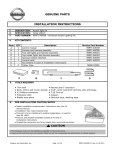
4. KIT CONTENTS:
Item
Qty
A
1
Description
Service Part Number
In-mirror RearView Monitor
999Q6 VX200
B
1
Camera
999Q6 VV030
C
1
Parts Kit
999Q6 VX600SP (Items D - P)
D
1
Harness
E
1
Camera Bracket
F
1
Wire Cover
G
20
Wire Tie
H
18
Foam Tape
I
4
Butyl Gum
J
2
Posi-Tap™
K
2
Well Nut
L
2
M3 x 6mm Phillip Screw
M
2
M4 X 12mm Phillip Screw
N
1
User Guide
O
1
Manual, Installation Instruction Download
999V2 AW000
P
1
A-Pillar Clip
76988 JM00A
5. PRE-INSTALLATION CAUTION / NOTES:
! WARNING
• Disconnect vehicle battery before installing RearView Camera Kit to prevent possible shock injury during
installation.
!
CAUTION
• Dealer installation recommended. This installation instruction will reference the service manual.
• This is a universal installation kit so all parts may not be used.
• Cut the excess wire tie(s) as flush with the head as possible. Face head of cable tie away from sheet
metal and other objects.
• Use caution when removing/re-installing interior components to avoid damage, scratches, or breaking of
mounting clips.
HOMELINK® AND THE HOMELINK HOUSE® ARE REGISTERED TRADEMARKS OF JOHNSON CONTROLS, INC.
Page 1 of 24
999Q6 VX800II
Rev. 08-17-10
In-mirror RearView Monitor - 370Z Roadster
!
CAUTION
• Ensure the slack on the installed harness is removed before securing wire ties.
• The harness routing needs to be followed as described to avoid interferences.
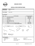
6. TOOLS REQUIRED:
1. Clean Rag
5. 3mm Flat Screwdriver
9. Torque Wrench
13. Fish Wire
2. Needle Nose Pliers
6. Panel Removal Tool
10. Drill
14. Center Punch Tool
3. T-20 Torx Head Driver
7. 10mm Socket Wrench
11. 5/16” Drill Bit
4. #1 Phillip’s Screwdriver
8. Side Cutters
12. 15/32” Drill Bit
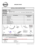
7. VEHICLE PREPARATION:
1) Apply parking brake.
2) Record the customer radio presets.
Presets
1
2
3
4
5
6
A
B
C
3) Make sure that the shift lever is engaged in the “P” position.
4) Turn the ignition switch OFF.
1) Removal of OE rearview mirror.
a) For vehicle’s having OE rearview mirror with connector attached to back of mirror, continue below,
step 1b. For vehicle’s containing OE rearview mirror without connector attached to back of mirror,
proceed to step 1g on next page.
Fig. 1
b) Disconnect 10-pin connector from back of mirror.
Harness will be tucked up into the headliner at a
later step.
c) Remove and discard wire harness cover, which is
attached from mirror base to headliner.
d) Using a T-20 Torx head driver, loosen the screw on
the mirror mount. (Fig. 1)
e) Slide the mirror base off of the button on the windshield. (Fig. 1)
f) Skip to step 2 on next page.
Page 2 of 24
999Q6 VX800II
Rev. 08-17-10
In-mirror RearView Monitor - 370Z Roadster
Fig. 2
g) Insert the flat end of a 4mm screwdriver into
the opening at the bottom of the mirror mount.
(Fig. 2)
h) Slide the screwdriver upward into the center of
the mirror mount until resistance is felt. Apply a
small amount of additional upward force to lift a
locking spring in the mount.
i) While still applying upward pressure with the
screwdriver, grasp the mirror bracket and lift
the mirror up towards the headliner and off the
mirror mounting bracket.
Fig. 3
2) Remove driver side kicking plate.
a) Pull up kicking plate to disengage the pawls.
(Fig. 3)
b) Remove kicking plate from body panel.
Fig. 4
Clip
3) Remove driver side dash side finisher.
a) Remove clip. (Fig. 4)
b) Remove dash side finisher fixing clips with
panel removal tool and then remove dash side
finisher. (Fig. 4)
Fig. 5
4) Using panel removal tool, loosen driver side weather
strip and remove from top of A-pillar to scuff plate
and from B-pillar. (Fig. 5)
Page 3 of 24
999Q6 VX800II
Rev. 08-17-10
In-mirror RearView Monitor - 370Z Roadster
Fig. 6
5) Remove driver side A-pillar trim.
a) Disengage front A-pillar fixing metal clips with
panel removal tool, and then pull up front A-pillar
to remove the pawls. (Fig. 6)
Sun Visor
Mount
Fig. 7
6) Remove driver side sun-visor assembly.
a) Remove sun-visor cap (1) fixing pawls with a
small flat screwdriver (A) wrapped into a tape (B).
(Fig. 7)
b) Remove sun-visor assembly Phillip’s fixing screw.
c) Disconnect vanity mirror lamp harness connectors and remove assembly.
Sun Visor
Clip Cover
Fig. 8
7) Remove driver side sun-visor holder. (Fig. 8)
a) Remove sun-visor holding fixing pawls with a
small flat screwdriver (A) wrapped into a tape (B).
(Fig. 8)
b) Remove sun-visor holder Phillip’s mounting screw
and remove holder.
Fig. 9
c) Loosen front of driver side headliner by gently
pulling downward to disengage clips. Headliner
does not need to be fully removed. (Fig. 9)
Page 4 of 24
999Q6 VX800II
Rev. 08-17-10
In-mirror RearView Monitor - 370Z Roadster
Fig. 10
Front of
Vehicle
1
8) Partially release lower clips from driver side rear
finisher by pulling outward on three lower clips. (Fig. 10)
2
Clips
Fig. 11
9) Partially remove trunk weather seal from rear plate
and LH luggage side finisher. (Fig. 11)
Front of
Vehicle
Fig. 12
Front of
Vehicle
a
10)Remove the following trunk components. (Fig. 12)
a) Trunk floor carpet.
b) Spare tire cover.
b
d
c) Trunk floor box cover (without spare tire).
c
d) Trunk floor box cover (with spare tire).
Page 5 of 24
999Q6 VX800II
Rev. 08-17-10
In-mirror RearView Monitor - 370Z Roadster
Fig. 13
11)Remove luggage rear plate. (Fig. 13)
a) Disengage rear trunk lid emergency handle (1)
fixing clip with panel removal tool (A). b) Using panel removal tool, remove luggage rear
plate fixing clips. c) Grab rear plate from bottom with hands and lift
upward to disengage the fixing pawls. 12)Remove the following interior parts as shown in Fig. 14. (Refer to vehicle service manual)
a) Trunk finisher front.
b) Driver side trunk side finisher.
c) Driver side trunk side box assembly.
Fig. 14
a
b
c
Page 6 of 24
999Q6 VX800II
Rev. 08-17-10
In-mirror RearView Monitor - 370Z Roadster
Fig. 15
13)Remove passenger side license plate lamp in numerical order shown. (Fig. 15)
a) Disconnect the license plate lamp connector.
b) Remove license plate lamp.
Push
Rotate
Fig. 16
Spare
Harness
Harness
Foam
Tape
For vehicle’s without spare 10-pin OE mirror
connector in overhead, proceed to step 14.
c) For vehicle’s containing the spare 10-pin harness used on the factory mirror, wrap 1 piece of
foam tape around connector. (Fig. 16)
d) Using panel removal tool, tuck harness up
into the headliner toward driver side. Ensure harness is not interfering with headliner.
(Fig. 16)
Fig. 17
14)Install In-mirror RearView Monitor mirror.
a) Plug the harness connector into the back of the
In-mirror RearView Monitor mirror.
b) Slide the In-mirror RearView Monitor mirror base over the button on the windshield.
(Fig. 17)
1.5 - 2.0 Nm
c) Using a T-20 Torx head driver, tighten the screw
on the mirror mount 1.5 - 2.0 Nm (1.3 ft - lbs).
(Fig. 17)
Fig. 18
Foam Tape
d) Wrap 1 piece of foam tape around harness and
using panel removal tool, tuck between headliner and roof above EC mirror. (Fig. 18)
Page 7 of 24
999Q6 VX800II
Rev. 08-17-10
In-mirror RearView Monitor - 370Z Roadster
Fig. 19
e) If a wire cover was removed from the OE mirror, discard OE wire cover and grab new wire
cover from kit contents.
Wire Cover
f) Route the harness into the groove of the wire
cover and attach to the mirror mount. (Fig. 19)
g) Slide the forks on top of the wire cover, into the
headliner. (Fig. 19)
Fig. 20
h) Grasp mirror and rotate downward. Check to
ensure wire cover sits flush against windshield. (Fig. 20)
i) If there is a gap between the wire cover and
windshield, ensure there is enough harness
slack from the mirror to the headliner. Adjust if
necessary.
Fig. 21
j) Wrap a piece of foam tape around harness at
center of sun visor and where the headliner
bends towards driver-side door. (Fig. 21)
Foam Tape
k) Using panel removal tool, tuck the wire harness
between the headliner and roof. (Fig. 21)
Fig. 22
Wire Tie
l) Route harness down driver-side A-pillar and
secure to existing vehicle harness with 3 wire
ties. (Fig. 22)
Page 8 of 24
999Q6 VX800II
Rev. 08-17-10
In-mirror RearView Monitor - 370Z Roadster
Fig. 23
m)Wrap 2 pieces of foam tape around mirror
harness (including red and black wires) and
tuck between vehicle body and center dash.
(Fig. 23)
Foam
Tape
Mirror
Harness
Fig. 24
n) Secure all mirror harness wires in footwell area
to existing vehicle harness with 2 wire ties.
(Fig. 24)
Wire Tie
Fig. 25
o) Separate Red and Black wires from mirror
harness. Red and black wires will be used at a
later step in the installation. (Fig. 25)
Wire Tie
Red and
Black Wires
Harness
p) Secure mirror harness (without Red and Black
wires) to existing vehicle harness with 1 wire
tie. (Fig. 25)
Fig. 26
Foam Tape
Vehicle
Front
15)Route harness to rear gate.
a) Secure harness to the inside of the vehicle
body with 5 pieces of foam tape, below existing
vehicle harness in scuff plate area, from A-pillar
to B-pillar. (Fig. 26)
Page 9 of 24
999Q6 VX800II
Rev. 08-17-10
In-mirror RearView Monitor - 370Z Roadster
Vehicle
Front
Fig. 27
Foam Tape
b) Secure harness to inside of the lower B-pillar
body with 2 pieces of foam tape. Ensure the
harness is routed so that the panel clip holes in
the body are not obstructed otherwise damage
to harness may occur. (Fig. 27)
Clip
Opening in Rear
Compartment
Fig. 28
Vehicle
Front
Fish Wire
Speaker
!
c) By accessing opening in driver side trunk compartment, route fish wire (or equivalent) into the
covertible compartment. Be sure to leave a
portion of the fish wire in the trunk compartment
for future use. (Fig. 28)
CAUTION
• Ensure engine is running when operating convertible top to prevent draining of vehicle battery.
• Operating convertible top excessively can cause an auto shut down, preventing operation of convertible
top. Refer to owner’s manual for details.
Fig. 29
d) Operate convertible top until rear convertible
lid is in the upright position and that the rear
convertible top is in the upright position, gaining access to the convertible compartment.
(Fig. 29)
Convertible
Lid
Convertible
Top
Page 10 of 24
999Q6 VX800II
Rev. 08-17-10
In-mirror RearView Monitor - 370Z Roadster
Fig. 30
Convertible
Top
Convertible
Lid
Vehicle Liner
Vehicle
Front
e) In order to gain access to covertible compartment, vehicle liner (inside convertible lid) will
need to be pulled back slightly. (Fig. 30)
Fig. 31
f) Route harness from inside driver’s compartment into convertible compartment. Ensure
harness is routed under vehicle bracket.
(Fig. 31)
Harness
Bracket
Fig. 32
g) Continue routing harness to the fish wire previously routed into convertible compartment.
h) Attach fish wire (or equivalent) to harness end. (Fig. 32)
Opening in Rear
Compartment
Fig. 33
Vehicle
Front
i) Completely close convertible top.
Fish Wire
Harness
j) Open trunk compartment door.
Speaker
k) Pull fish wire, with harness, into trunk compartment. (Fig. 33)
Page 11 of 24
999Q6 VX800II
Rev. 08-17-10
In-mirror RearView Monitor - 370Z Roadster
Fig. 34
l) Continue routing harness along side existing
vehicle harness to rear of trunk, and towards
passenger side. Be sure to route harness under vehicle bracket. (Fig. 34)
Spare
Tire
Video
Cable
Front of
Vehicle
Vehicle
Bracket
Camera
Bracket
Fig. 35
m)Remove fish wire from harness. 16)Establish location to attach camera bracket to vehicle body.
a) Have a center punch tool readily available.
Rear Gate
Request
Switch
b) Ensure correct orientation of camera is established as per illustration. (Fig. 35)
Passenger Side
License Plate
Light Opening
Camera
Bracket
c) Place camera bracket onto rear of vehicle, near
passenger side license plate light opening and
rear gate request switch. (Fig. 35)
Fig. 36
d) Ensure camera bracket is pushed inward and
toward the driver side of the trim to ensure the
bracket is flush against “pocket” (a portion of
the bracket has been removed from the illustration to better depict the necessary information).
(Fig. 36)
Rear Gate
Request
Switch
Pocket
Center Camera
Bracket
Hole
License
Plate Light
Opening
Outer Fig. 37
Hole
e) While camera bracket is still positioned flush
against the “pocket”, use a center punch tool to
mark the two outer holes. (Fig. 37)
f) Using center punch tool, mark the center
hole just below the curvature of the opening.
(Fig. 37)
Outer
Hole
Pocket
Page 12 of 24
999Q6 VX800II
Rev. 08-17-10
In-mirror RearView Monitor - 370Z Roadster
Fig. 38
17)Drill out camera mounting holes.
a) Remove camera bracket from vehicle body.
b) Protect rear of vehicle body with tape or shop
towel before proceeding to next step.
5/16”
Hole
c) Using a drill and a 5/16” drill bit, drill out the two
outer locating holes. (Fig. 38)
Fig. 39
d) Using a drill and a 15/32” drill bit, drill out the
center locating hole. (Fig. 39)
15/32”
Hole
Fig. 40
e) Insert a well nut into the two outer holes until
the head of the nut is pressed up against the
plastic trim. (Fig. 40)
Well Nut
Fig. 41
Camera
Cable
18)Attach camera to camera bracket.
Access
Hole
a) Orient camera and camera bracket as shown.
Note locations of access hole, camera label
and camera cable. (Fig. 41)
Camera Label
(Bottom of
Camera)
Page 13 of 24
999Q6 VX800II
Rev. 08-17-10
In-mirror RearView Monitor - 370Z Roadster
Fig. 42
Camera
Screw
Hole
Access
Hole
b) Attach camera onto camera bracket and secure
using (2) M3 x 6mm Phillip’s screws (smaller
screws) as shown. Note access hole in order
to secure one of the camera screws. (Fig. 42)
Phillips
Screwdriver
19)Attach camera bracket to vehicle body.
Center
Hole
Fig. 43
a) Insert camera harness through center hole ensuring harness is routed downward toward the
bumper. (Fig. 43)
Camera
Harness
b) Ensure correct orientation of camera and
camera bracket are identified and place bracket
onto vehicle body. (Fig. 43)
c) Ensure camera bracket is flush against “pocket”
(refer to figure 36 for reference).
Fig. 44
Camera
Bracket
d) Insert (2) M4-0.7 X 12MM well nut screws
(larger screws) into locating holes and loosely
secure using a Phillips screwdriver in a uniform
manner. If a uniform manner is not followed
when loosely securing screws, difficulty could
arise when trying to install screws. (Fig. 44)
e) Now securely tighten screws using Phillips
screwdriver.
Well Nut
Screw
Fig. 45
Rear Gate Request
Switch
Camera
Harness
Passenger Side
License Plate
Light Opening
f) Route camera harness toward bottom of vehicle bumper area. (Fig. 45)
Page 14 of 24
999Q6 VX800II
Rev. 08-17-10
In-mirror RearView Monitor - 370Z Roadster
Fig. 46
Grommet
20)Locate vehicle grommet at rear trunk compartment
on passenger side.
Spare
Tire
a) Pull grommet outward, disengaging from vehicle body. (Fig. 46)
Front of
Vehicle
Fig. 47
21)Cut rear grommmet to allow for routing of camera
harness.
8.5mm
a) Using side cutters, cut a slit in the grommet
approximately 8.5 mm in length on the bottom
side. Once complete, cut a small triangular
portion (approximately 4.5 mm in diameter) out
of the grommet to allow for the camera harness. (Fig. 47)
Slit in
Grommet
Fig. 48
Mirror
Harness
Spare
Tire
b) Route mirror harness through passenger side
grommet and to the bottom of the vehicle near
bumper area. (Fig. 48)
Front of
Vehicle
Fig. 49
Rear
Bumper
Camera Mirror Harness
Harness
Connector
Connector
c) Locate both the camera connector and mirror
harness connector. (Fig. 49)
d) Remove black electrical tape and tubing from
mirror harness end, exposing connector, in
order to connect harness to camera harness.
e) Route camera harness connector to mirror harness connector and connect. (Fig. 49)
Page 15 of 24
999Q6 VX800II
Rev. 08-17-10
In-mirror RearView Monitor - 370Z Roadster
Fig. 50
f) Pull mirror harness, with camera harness,
through passenger side grommet and into vehicle trunk compartment. (Fig. 50)
Mirror Harness
Camera Harness
Front of
Vehicle
g) Ensure excess slack of camera harness is
pulled into the vehicle compartment.
22)Open engine hood.
a) Disconnect negative battery terminal.
23)Secure gray end of the wire tap to larger Orange
Wire in fuse panel area in driver side kick panel area.
(Fig. 51)
a) See steps 24 - 28 for wire tap installation instructions.
b) Red mirror harness wire will be used as the accessory wire.
MA01
Red
Black
Fig. 51
Green Orange
MA01
Orange
24)Tap vehicle wire. (Fig. 52)
Fig. 52
b)
a)
c)
a) Remove cap (slot side) from tap body.
b) Slide the cap around vehicle wire.
c) Tighten the tap TIGHT with finger pressure.
NOTE:
Do not re-use the tap for subsequent re-installation.
Page 16 of 24
999Q6 VX800II
Rev. 08-17-10
In-mirror RearView Monitor - 370Z Roadster
Fig. 53
25)Inspect the tap to ensure correct installation.
(Fig. 53)
NOTE:
Avoid putting pressure on the vehicle wire and
tap for the rest of the installation.
i Straight and evenly spaced all the way around
ii. Tight and minimize gap (wire jacket should be crushed)
Fig. 54
26)Tap accessory wire. (Fig. 54)
c) Insert wire to here
c)
a)
d)
f) Tighten
Fig. 55
a) Remove tap (non-pierce) side from tap.
b) Remove the protective stub.
c) Insert wire through the non-pierce side opening.
d) Spread the individual strands into fan shape.
e) Insert wire into the tap body and ensure that it
is all the way in.
f) Tighten the tap TIGHT with finger pressure. 27)Confirm the tapped accessory wire. (Fig. 55)
a) Inspect the tap to ensure correct installation.
b) Test the signal to ensure that it is working
properly.
NOTE:
Avoid putting pressure on the vehicle wire, tap,
and accessory wire for the rest of the installation.
i. Straight and evenly spaced all around
ii. Tight and no gap
iii. Test the signal
Fig. 56
b)
28)Secure the tap. (Fig. 56)
a)
Existing
Harness
Accessory
Harness
a) Secure the tapped wire on the non-pierce side
to the body of the posi-tap with electrical tape
(2 revolutions).
b) Secure the body to harness where vehicle wire
is being tapped with electrical tape (2 revolutions).
Page 17 of 24
999Q6 VX800II
Rev. 08-17-10
In-mirror RearView Monitor - 370Z Roadster
Fig. 57
29)Locate the 10mm ground bolt in driver side cowl
area (behind carpet) and remove. (Fig. 57)
a) Install ring terminal from Black wire of mirror harness over ground bolt and reinstall.
(Fig. 57)
Wire Tie
Excess
Wire
Ground
Bolt
Vehicle
Grommet
b) Ensure ground bolt is tightened to 5.9 - 8.0 Nm.
c) Bundle excess Red and Black harness wires
and secure, along with mirror harness, to existing vehicle harness with 1 wire tie. (Fig. 57)
Fig. 58
30)Locate vehicle grommet at rear in trunk compartment on driver side. (Fig. 58)
Spare
Tire
Front of
Vehicle
!
CAUTION
• Do not use sharp objects or objects that can damage electrical wires on next step. Plastic panel tool is
acceptable.
Electrical
Tape
Fig. 59
a) If present, carefully remove electrical tape from
existing vehicle harness to expose electrical
wires. (Fig. 59)
Page 18 of 24
999Q6 VX800II
Rev. 08-17-10
In-mirror RearView Monitor - 370Z Roadster
31)Secure Green harness wire to existing vehicle reverse circuit.
Fig. 60
Tan Wire
a) Locate Tan Wire in existing wire bundle at
driver side rear trunk compartment. (Fig. 60)
b) See steps 24 - 28, pages 16 - 17 for wire tap
installation instructions.
c) Green mirror harness wire will be used as the
accessory wire.
32)Verify a clear image is displayed on the monitor.
Fig. 61
a) Reconnect negative battery cable.
b) Turn the ignition switch to ON.
E
AG
IM
c) With your foot on the brake pedal, move the
gear selector lever into reverse.
d) A clear image should display in the left hand
side of the mirror. (Fig. 61)
e) Move the gear selector lever back into park.
The image should now disappear.
f) Turn the ignition switch to OFF.
!
CAUTION
• Apply butyl gum to prevent potential leaks.
Fig. 62
33)Secure camera harness.
a) In trunk compartment, wrap a piece of butyl
gum around camera harness at the point where
the harness lines up to the vehicle grommet.
(Fig. 62)
Slit in
Grommet
Front of
Vehicle
Butyl Gum
Page 19 of 24
999Q6 VX800II
Rev. 08-17-10
In-mirror RearView Monitor - 370Z Roadster
Fig. 63
Spare Tire
Butyl Gum
b) Re-install vehicle grommet to body, ensuring
the slit in the grommet is facing downward.
(Fig. 63)
c) To ensure water integrity, confirm that the grommet is installed properly duirng re-installation.
Front of
Vehicle
!
CAUTION
• Ensure engine is running when operating convertible top to prevent draining of the vehicle battery.
• Operating convertible top excessively can cause an auto shut down, preventing operation of convertible
top. Refer to owner’s manual for details.
Fig. 64
d) Operate convertible top until rear convertible
lid and rear of convertible top are in the upright
position, gaining access to the convertible compartment. (Fig. 64)
Convertible
Lid
Convertible
Top
Fig. 65
Convertible
Top
Vehicle Liner
Convertible
Lid
e) In order to gain access to covertible compartment, vehicle liner (inside convertible lid) will
need to be pulled back slightly. (Fig. 65)
Page 20 of 24
999Q6 VX800II
Rev. 08-17-10
In-mirror RearView Monitor - 370Z Roadster
Front of
Vehicle
Bracket
Fig. 66
f) Secure harness to existing vehicle harness in
convertible area with 2 pieces of foam tape.
Ensure harness is routed under vehicle bracket. (Fig. 66)
Foam
Tape
Front of
Vehicle
Fig. 67
g) Secure harness to vehicle body in convertible
area with 1 piece of foam tape. (Fig. 67)
Foam
Tape
Fig. 68
Front of
Vehicle
h) Completely close convertible top.
Rear
Speaker
i) Open trunk compartment door.
Wire Tie
j) Secure harness to existing vehicle harness
in trunk compartment area with 2 wire ties.
(Fig. 68)
Wire Tie
Rear
Speaker
Fig. 69
k) Secure harness to existing vehicle harness
in trunk compartment area with 2 wire ties.
(Fig. 69)
Spare Tire
Front of
Vehicle
Page 21 of 24
999Q6 VX800II
Rev. 08-17-10
In-mirror RearView Monitor - 370Z Roadster
Fig. 70
l) Secure camera harness and mirror harness to
existing vehicle harness in trunk compartment
area with 2 wire ties. (Fig. 70)
Front of
Vehicle
Spare Tire
Wire Tie
Fig. 71
Excess Mirror
Harness
m)Secure harness to existing vehicle harness
in trunk compartment area with 3 wire ties.
(Fig. 71)
n) Bundle excess mirror harness and secure to existing vehicle harness with 2 wire ties. (Fig. 71)
Spare Tire
Wire Tie
Front of
Vehicle
Fig. 72
NE
Compass Display
Green LED
Rearward
Photocell
Dark Cloth or
Towel
Fig. 73
Homelink Buttons
Red LED
34)Testing
a) Reconnect the vehicle’s negative battery cable
(if not already connected).
b) Tighten negative battery terminal nut to 4.1 Nm.
c) Turn the ignition switch to ON.
d) Ensure vehicle is in a failure well lit area.
e) Check to see that the green LED is illuminated.
If it is not, press the “
“ button to turn it on.
f) Cover the forward-looking photocell (located to
the driver side of the wire harness connection
on the back of the mirror) with a dark cloth or
towel. After a few seconds, the mirror should
begin to darken. Timing will vary with ambient
light levels and a flashlight may be shined on
the rearward photocell if needed, to accelerate
effect.
g) Remove the cover from the forward-looking
photocell and the mirror will begin to clear.
h) Push the “
“ button to ensure compass display shows either a direction such as “NE” or a
“C”, and that it can be turned ON and OFF.
i) Push each Homelink® button one at a time
and verify that the LED indicator to the left of
the center switch illuminates with a red LED.
(Fig. 73)
35)Re-install the remaining components, referring to the
service manual for the vehicle
36)Clean interior of vehicle.
Page 22 of 24
999Q6 VX800II
Rev. 08-17-10
In-mirror RearView Monitor - 370Z Roadster
CAUTION
!
• Use caution when re-installing interior components to avoid damage, scratches, or breaking of mounting
clips. Refer to the vehicle specific service manual for more information.
• Trim pieces found to have witness marks or broken clips are not to be reinstalled.
37)Set Compass Zone
a) With the display turned “ON”, push the “
“
button for 3 seconds, until a number appears
in display (numbers correspond to regional
compass zones).
b) Press and release “
“ button to scroll through
zone numbers.
c) Release “
“ button when correct zone
number is displayed. Zone number will disappear and display will return to showing either a
directional heading or a “C” after 5 seconds of
no switch activity.
38)Calibrate Compass
a) Drive vehicle in circles (360°) at 5 mph or less
until compass display window shows a direction.
Fig. 74
1
2
2
15
3
4
3
5
6
7
8
9
12
10 11
14
13
14
13
4
12
11
5
10
6
7
8
9
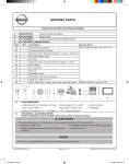
9. Post Installation Check Sheet
Ensure all trim panels are fully seated properly.
Inspect the vehicle interior and exterior for damage.
Confirm proper operation of vehicle systems.
Confirm back up lamps.
Confirm license plate lights.
Confirm trunk / cargo light.
Confirm driver side speaker in driver side rear panel (if equipped).
Confirm proper sunroof operation and perform the reset procedure if necessary. Place the User Guide in the glove box.
Reset radio presets to the recorded settings.
Check the trim for proper flush fit after re-installing the interior components. Posi-Tap™ is protected by patent # 5,228,875 5,695,369 5,868,589 6,692,313 Jap 2881414 Aus 708700
Tia 103534 Can 2204826 Mex 200626 Korea 477279 China Z197105562.9 & others pending.
Page 23 of 24
999Q6 VX800II
Rev. 08-17-10
In-mirror RearView Monitor - 370Z Roadster
Verify In-mirror RearView Monitor has the correct amount of rear bumper present. Cut out the
“Go-No-Go” gauge below and place on mirror display (dimensions of cut out must be measured prior to
cutting to ensure accuracy of printer).
Bumper Visual = Not Acceptable
44mm
Bumper Visual = Acceptable
71mm
Verify the camera is operating properly.
Camera should meet the below performance requirements.
The grey area indicated
must be included in the
display
Vehicle width both
sides 200 mm
300 mm
5,000 mm
Bold lines indicate the
actual field of vision.
A
B
Page 24 of 24
A: 300 mm max.
B: 5,000 mm min.
999Q6 VX800II
Rev. 08-17-10