1
LI-6262 CO2/H2O Analyzer
Operating and Service Manual
ALYZER
ZERO
CO2/H2O AN
SPAN
262
Model LI-6
CO2
ZERO
1
2
3
FUNCTION
4
5
6
EEX, ↑
8
↓
7
9
0
.
ENTER
C
SPAN
ON
H2O
®
READY
OFF
Publication Number 9003-59
March, 1996
Software Version 2.02
LI-COR, inc.
P.O. Box 4425
4421 Superior Street
Lincoln, Nebraska 68504
Phone: (402) 467-3576
FAX: (402) 467-2819
Toll-free 1-800-447-3576 (U.S. & Canada)
U.S. and Foreign Patents Pending
Federal Communications Commission
Radio Frequency Interference Statement
This instrument generates and uses radio frequency energy and if not installed and used
properly, that is, in strict accordance with these instructions, may cause interference to
radio and television reception. This equipment is required to comply with the limits for a
Class 'A' computing device pursuant to Subpart J of Part 15 of the FCC rules. A Class 'B'
device is designed to be used in a residential area. Class 'A' specifications are designed to
provide reasonable protection against such interference in a commercial environment.
This equipment has been type tested and found to comply with the limits for Class 'A'
computing devices, and is verified in accordance with FCC Part 15 Subpart J for the Class
'B' limits for a computing device. However, there is no guarantee that interference will not
occur in a particular installation. If this equipment does cause interference to radio or
television reception that can be determined by turning the instrument off and on, the user is
encouraged to try to correct the interference by one or more of the following measures:
1. Reorient the receiving antenna.
2. Relocate the instrument with respect to the receiver.
3. Plug the instrument into a different outlet (if so equipped) so that the instrument and
receiver are on different branch circuits.
If necessary, the user should consult LI-COR or an experienced radio/television technician
for additional suggestions.
The Federal Communications Commission has prepared a booklet entitled "How to
Identify and Resolve Radio-Television Interference Problems" which may be helpful to
you. This booklet (stock # 004-000-00345-4) is available from the Superintendent of
Documents, U.S. Government Printing Office, Washington, D.C. 20402.
ii
NOTICE
The information contained in this document is subject to change without notice.
LI-COR MAKES NO WARRANTY OF ANY KIND WITH REGARD TO THIS MATERIAL,
INCLUDING, BUT NOT LIMITED TO THE IMPLIED WARRANTIES OF MERCHANTABILITY AND FITNESS FOR A PARTICULAR PURPOSE. LI-COR shall not be liable for
errors contained herein or for incidental or consequential damages in connection with the
furnishing, performance, or use of this material.
This document contains proprietary information which is protected by copyright. All rights are
reserved. No part of this document may be photocopied, reproduced, or translated to another
language without prior written consent of LI-COR, Inc.
Copyright 1990, LI-COR, Inc.
______________________________________________________________
IBM is a registered trademark of International Business Machines Corp.
PC-TALK is a trademark of Freeware.
ProComm is a trademark of Data Storm Technologies.
Printing History
New editions of this manual will incorporate all material since the previous editions. Update
packages may be used between editions which contain replacement and additional pages to be
merged into the manual by the user.
The manual printing date indicates its current edition. The printing date changes when a new
edition is printed. (Minor corrections and updates which are incorporated at reprint do not cause
the date to change).
1st Printing - April, 1990
2nd Printing - October, 1991
3rd Printing - March, 1996
iii
Table of Contents
Section I. Unpacking and Inspection
1.1 What's What ......................................................................................
1.2 Checking the Batteries ......................................................................
1-1
1-3
Section II. Setup and Operation
2.1
2.2
2.3
2.4
Setup and Operation .........................................................................
Power On ...........................................................................................
Gelman Filter Installation ..................................................................
Absolute vs. Differential Mode Operation ........................................
2-1
2-3
2-4
2-5
Section III. Theory Of Operation
3.1
3.2
3.3
3.4
3.5
3.6
3.7
General Description ..........................................................................
Calculating Gas Concentration - General ..........................................
Calculating CO2 Concentration .........................................................
Calculating H2O Concentration ........................................................
Pressure Broadening Due to Water Vapor.........................................
Dilution Corrections ..........................................................................
Cr is Unknown. Measuring C r Against Cs = 0 .................................
3-1
3-2
3-6
3-6
3-8
3-11
3-12
Section IV. Calibration
4.1
4.2
4.3
4.4
4.5
4.6
4.7
Calibration - General Information .....................................................
Differential Mode Calibration ...........................................................
Absolute Mode Calibration ...............................................................
H2O Absolute Mode Caution ............................................................
Pressure Corrections ..........................................................................
Setting the Zero and Span in Software ..............................................
Using the LI-670 Flow Control Unit .................................................
iv
4-1
4-2
4-5
4-5
4-9
4-9
4-12
Section V. System Software
5.1 Using the Keypad .............................................................................. 5-1
5.2 Software Overview ............................................................................ 5-2
5.3 Console Commands ........................................................................... 5-3
Section VI. Interfacing
6.1
6.2
6.3
6.4
6.5
6.6
General Information .........................................................................
RS-232C Data Transfer .....................................................................
Analog Output ...................................................................................
Auxiliary Channel Inputs...................................................................
Temperature Output ...........................................................................
Using the 6262-03 Pressure Transducer ............................................
6-1
6-2
6-7
6-13
6-14
6-15
Section VII. Maintenance
7.1
7.2
7.3
7.4
7.5
7.6
Recharging the 6000B and 6200B Batteries .....................................
Opening the LI-6262 .......................................................................
Internal Soda Lime/Desiccant ...........................................................
External Soda Lime/Desiccant .........................................................
Fan Filter ...........................................................................................
Fuses .................................................................................................
Section VIII. Troubleshooting
APPENDIX A.
APPENDIX B.
APPENDIX C.
APPENDIX D.
APPENDIX E.
APPENDIX F.
APPENDIX G.
APPENDIX H.
Warranty
Specifications
List of Suppliers
Software Command Index
Channel Code Headers
LI-6262 Console Commands
Saturation Vapor Pressure Table
Connector Descriptions
Sample Program
v
7-1
7-1
7-2
7-4
7-6
7-6
LYZER
ZERO
CO2/H2O ANA
SPAN
ZERO
SPAN
ON
H2O
®
2
3
FUNCTION
4
5
6
EEX, ↑
8
9
↓
7
0
.
ENTER
C
1
62
Model LI-62
CO2
READY
OFF
1
Unpacking &
Inspection
1.1 What's What
This procedure should be followed if you have just taken delivery on your
LI-6262. Check the packing list to verify that you have received everything
that was ordered and that you have also received the following items:
●
Calibration Sheet - This data sheet contains a copy of the calibration
information entered into the analyzer at the factory. Keep it in a safe
place for future reference, or in case calibration data must be re-entered.
●
Console Command Sheet - A quick reference card for entering console
commands via the LI-6262 keypad or from an external terminal.
●
Spare Parts Kit - This kit contains replacement parts for your LI-6262.
As you become familiar with the analyzer you will learn which items to
keep close at hand and which items can be stored away.
●
External Scrubber and Desiccant Tube - This tube is used during
normal operation. Several spare gaskets and adhesive disks have been
included for future use.
●
1000-90 Data Communications and Utility Software - This software
can be used to communicate with an IBM PC/XT/AT/PS2 or
compatible. The software is provided on 3 1/2 inch diskettes.
●
RS-232C Cable - (Part #392-02874) DTE to DCE, used to connect the
LI-6262 (DCE) to a DTE device such as an RS-232C printer.
●
RS-232C Gender Changer - (Part #392-02977) Female-to-female
gender changer, used to connect the RS-232C cable to most computers.
Unpacking & Inspection
1-1
Section 1
There are several optional accessories available for use with the LI-6262,
including:
6262-03 Pressure Transducer - measures pressure in the sample
optical cell and its millivolt signal is used by the LI-6262 analyzer
software to calculate pressure values. CO2 and H2O readings are then
automatically corrected by the software for any detected pressure
changes.
6262-04 Reference Pump - designed to purge the reference cell of H2O
during absolute mode operation. Air flow created by movement of the
chopping shutter disc is sufficient to purge the reference cell of CO2, but
it is not sufficient to remove all the water vapor in the reference cell.
For this reason, an auxiliary pump such as the 6262-04 or the LI-670
Flow Control Unit must be used when operating in absolute mode.
6000B Rechargeable Battery (provides 3.2 hours of battery life).
6200B Rechargeable Battery (provides 6.4 hours of battery life).
LI-6020 Battery Charger (92-138/184-276 VAC, 47 to 63 Hz).
1800-04 RS-232C Cable - Used to connect the LI-6262 (DCE) to a
standard IBM AT-type 9-pin RS-232C communications port).
In addition, LI-COR manufactures a portable dew point generator (LI-610),
and a flow control unit (LI-670), which are valuable accessories for
calibrating and operating the LI-6262.
LI-610 Portable Dew Point Generator
The LI-610 is an ideal field-portable system for calibrating the LI-6262, and
can also be used to provide a known water vapor source for use in environmentally controlled measurement chambers.
The LI-610 is a precision instrument that provides a controlled water vapor
source of known dew point. The LI-610 has the ability to generate stable
dew points from 0 to 50 °C with high accuracy (± 0.2 °C). The water vapor
source can be derived from any input air stream, including ambient air,
eliminating the need for external tanks or mixing of gases.
The dew point temperature of the air stream can be viewed on the LI-610’s
4 1/2 digit LCD display, or output to the LI-6262 directly, as an analog
1-2
Unpacking & Inspection
Section 1
signal. Analog output is linear, and the 0-50 °C dew point range is scaled
over 0-5 volts (100mV/°C).
LI-670 Flow Control Unit
The LI-670 is a valuable accessory for use with the LI-6262, which can be
used for a variety of calibration and gas exchange measurement functions.
In its simplest form, the LI-670 is used as a constant source of air flow to the
LI-6262. Independent pumps and rotameters allow variable flow rates
through the LI-6262 sample and reference cells, if desired.
For calibration of the LI-6262, soda lime and desiccant tubes provide a zero
gas source; a span gas can be swapped between cells to adjust for any zero
offset present during calibration.
The LI-670 also can be used as a power source for the LI-6262; a built-in
low battery detection circuit monitors battery life of the system. Mounting
brackets are included for attaching the LI-670 and LI-6262, making the
system completely portable.
1.2 Checking the Batteries (If purchased)
Batteries are tested and fully charged when they leave the factory, but they
may discharge during shipping. It is a good idea to test each battery to see if
it is charged. If the batteries are below 12V, they should be charged before
use. Refer to Section 7.1 for charging instructions.
NOTE: Never store batteries in a discharged state. Charge stored batteries every 3 months.
Unpacking & Inspection
1-3
LYZER
ZERO
CO2/H2O ANA
SPAN
ZERO
2
3
FUNCTION
4
5
6
EEX, ↑
8
9
↓
7
0
.
ENTER
C
1
62
Model LI-62
CO2
SPAN
ON
H2O
®
READY
OFF
2
Setup &
Operation
This section will describe the steps necessary for you to set up the hardware
and software in your LI-6262 to begin making measurements. Follow these
steps to configure your analyzer; where noted, the steps are described in
more detail in this and other sections.
2.1 Setup and Operation
1.
Install Gelman filters.
The Gelman filters are used externally, and must be inserted in the
Sample and Reference airstreams upstream from the analyzer. See
Section 2.3, Gelman Filter Installation below.
2.
Prepare a soda lime/desiccant tube, as described in Section 7.4, and
attach to the SCRUBBER holder on the back panel.
3.
Absolute or Differential mode operation?
The LI-6262 can be operated in absolute or differential mode. In
absolute mode, the reference cell contains a zero concentration of CO2
and H2O. The sample cell is connected to the unknown gas to be
measured. The signal from the sample cell is compared to the zero gas
reference signal to provide absolute measurements of CO2 and H2O. In
differential mode, the reference cell contains a non-zero gas of known
concentration. The difference between absorption in the sample cell
and in the reference cell is measured. Configuring the LI-6262 for
differential or absolute mode operation requires slightly different hose
connections; see Absolute vs Differential Mode Operation below.
4.
Turn the power ON.
The LI-6262 can be operated with AC or DC power. See Section 2.2,
Power On below.
5.
Calibrate the analyzer as described in Section 4.
Setup & Operation
2-1
Section 2
6.
Connect sample airstream to be measured.
7.
Configure analyzer for data output.
Data can be obtained from the LI-6262 in several different ways; from
the display, via RS-232C output, or from one of the analog output
channels. See Section 6, Interfacing, for more information.
8.
Configure the software.
All software commands are executed by pressing FUNCTION and then
entering a two-digit function code. Some codes execute a function
directly, while others access scrollable lists of options, or other
functions. Items in lists can be selected by scrolling the list with the
arrow keys and pressing ENTER.
●
Enter the station barometric pressure. Press FCT, followed by 77,
and enter the barometric pressure, in kPa.
Pressure may also be input continuously using the 6262-03 Pressure
Transducer from LI-COR, or through auxiliary channel 15 with an
external pressure sensor, as described in section 6.4.
●
Set the parameters for RS-232C output, if necessary. Press FCT,
followed by 17, and enter the data output parameters.
●
Set the Print List (FCT 13).
Data from up to ten different channels may be sent to the RS-232C
port at a specified interval. See Section 5, FCT 13.
●
Set Auto Print (FCT 14).
Enter specified interval in seconds (0.1-3600) at which to transmit
data (defined at FCT 13) to the RS-232C port. See Section 5, FCT
14.
●
Set Auto Header (FCT 15).
The column header interval is the number of data lines which will
be printed between column headers. See Section 5, FCT 15.
2-2
Setup & Operation
Section 2
●
Set the displays (FCT 91-99).
The LCD display has two lines, and each line can be configured to
show any channel code 21-29 (CO2 ), 31-39 (H 2O), or 41-47
(MISC). As many as nine two-line display configurations can be
defined by the Set Displays routine. Each display is identified by a
number 1 through 9, and can be viewed by pressing the appropriate
number without pressing FCT. See Section 5, FCT 04.
9.
Begin making measurements.
2.2 Power On
1.
If a LI-COR rechargeable battery is being used, connect it to the
10.5-16VDC battery connector on the rear panel. The 6000B
Rechargeable Battery will provide power for approximately 3.2 hours at
25 °C, or 2.4 hours at 40 °C. The 6200B Rechargeable Battery has
twice the capacity of the 6000B. Instructions for recharging these
batteries are given in Section 7.1.
One set of battery leads with a 3-pin plug is included in your spare parts
kit for connection to a user-supplied battery (10.5 - 16VDC, 1.5 amp
maximum current required) or other DC power supply.
If AC line voltage is being used, make sure the AC VOLTAGE selector
on the back panel is set correctly (choose the 115 setting for 100130VAC, or the 220 setting for 200-260VAC), and plug the line cord
into the receptacle on the back panel.
2.
Turn the power switch on the front panel ON. The fan will run, and
after a few seconds, the chopper motor will come up to speed. The
READY light on the front panel will come on after 1-3 minutes. (The
higher the ambient temperature, the longer it takes). Any one of the
following conditions will prevent the READY light from illuminating:
●
●
●
●
Ambient temperature greater than about 55 °C.
Level of CO2 is too high in the reference cell (greater than about
3000 ppm).
CO2 or water vapor in the detector, caused by the internal soda
lime/desiccant bottle being exhausted.
Span potentiometer on the front panel is defective (open).
Setup & Operation
2-3
Section 2
Low Battery Voltage
IMPORTANT: The LI-6262 has no built-in circuitry for monitoring
battery voltage. When battery voltage drops below approximately 10.5
volts, the analyzer will shut down, and data transmission will stop. It is
therefore suggested that battery voltage be monitored regularly to avoid
system shutdown.
You may wish to monitor battery voltage with an external voltmeter, or use a
timer with an alarm to alert the user to possible system shutdown. If you
intend to operate the LI-6262 with battery power for more than 3 hours with
the 6000B (6 hours with the 6200B), it is recommended that a user-supplied
battery with a larger storage capacity be connected using the battery leads
included with the LI-6262, or that several batteries be used in parallel for
longer operation.
2.3 Gelman Filter Installation
IMPORTANT: Always install the external air filters before operating
the LI-6262. Insert filters into both the SAMPLE and REFERENCE
airstreams before they enter the LI-6262. Failure to do this will lead to
contamination of the sample and reference optical paths, which can
cause large zero offsets that may require expensive repairs.
The Gelman polypropylene filters included use PTFE filter elements with a
1 µm pore size. They have excellent particle retention, very low water
sorption, little flow restriction and small internal volumes. These filters will
not fit inside the LI-6262 case, and must be used externally.
In absolute mode, insert a filter between the scrubber tube outlet (top) and
the REFERENCE IN port (Figure 2-3). Use a jumper tube to connect the
REFERENCE OUT port to the TO CHOPPER port. The scrubber tube inlet
(bottom) is connected to the FROM CHOPPER port. Air supplied to the
sample cell must also pass through a filter before it enters the LI-6262.
In differential mode, place a filter in the sample airstream before it enters the
SAMPLE IN port on the LI-6262. Place a second filter in the reference
airstream before it enters the REFERENCE IN port.
2-4
Setup & Operation
Section 2
Replace the filters when flow rates drop due to particle retention, or when
the apparent LI-6262 response to changes in humidity becomes slow due to
filter retention of hygroscopic material.
When using the LI-6262 in high flow rate applications (e.g. eddy correlation)
or where sample air is particularly dirty, you may consider stacking two
filters in series. For maintenance, replace the filter furthest upstream from
the analyzer with the filter closest to the analyzer and replace the filter
closest to the analyzer with a new filter.
Air In
1µm
PTFE
a rt
IN
IN
µP
#9
967-0 0 8
Air Out
Install the new filter(s) with the blue lettering facing away from the
SAMPLE IN or REFERENCE IN ports.
Instruments with serial numbers of IRG3-239 and below were shipped with
internal Balston filters. Balston filters have good particle retention with low
flow resistance, but they equilibrate slowly with changing humidities, thus
degrading the apparent response time and performance of the LI-6262.
Replace the Balston filters with external Gelman filters as described above.
We recommend that the SAMPLE IN and REFERENCE IN ports be covered
with the dust caps provided or attached to an airline when the instrument is
not in use. This will prevent dust from entering the instrument downstream
from the filters where it can enter the optical paths.
Replacement Gelman Acro 50 filters can be obtained from LI-COR (part #
9967-008).
2.4 Absolute vs. Differential Mode Operation
The LI-6262 may be operated in either absolute or differential modes to
simultaneously measure CO2 and H2 O in any units. The following
discussion will help you to set up the analyzer to measure these outputs.
Setup & Operation
2-5
Section 2
Prepare a soda lime/desiccant tube, as described in Section 7.4, and attach to
the SCRUBBER holder on the back panel.
Differential Mode Operation
●
Orient the scrubber tube so that the soda lime is on the bottom and the
magnesium perchlorate is on top.
●
Attach the bottom hose (nearest the soda lime) to the FROM CHOPPER
fitting.
●
Attach the top hose (nearest the perchlorate) to the TO CHOPPER fitting
(Figure 2-1).
Figure 2-1. Hose connections for operation in differential mode.
IMPORTANT: Attach the hoses as shown in Figure 2-2. The hose
nearest the soda lime is attached to the FROM CHOPPER fitting, and
the hose near the magnesium perchlorate is attached to the T O
CHOPPER fitting. This ensures that CO2 is purged first, and then water
vapor. If this sequence is reversed, the air will pick up water vapor
from the soda lime before being returned to the chopper housing.
2-6
Setup & Operation
Section 2
To chopper
Magnesium
Perchlorate
Fiberglass Wool
Soda Lime
From chopper
Figure 2-2. Hose attachments to external soda lime/desiccant tube assembly.
Absolute Mode Operation
IMPORTANT: Air flow created by movement of the chopping shutter
disc is sufficient to purge the reference cell of CO2, but is not sufficient
to remove all of the water vapor in the reference cell. For this reason an
auxiliary pump such as the 6262-04 must be used when operating in
absolute mode. See Section 4.4 for more information.
●
Orient the scrubber tube so that the soda lime is on the bottom and the
magnesium perchlorate is on the top.
●
Attach the bottom hose (nearest the soda lime) to the FROM CHOPPER
fitting. An auxiliary pump should be placed between the F R O M
CHOPPER fitting and the bottom hose of the scrubber tube. Make sure
the pump is oriented to pump in the direction indicated in Figure 2-3.
●
Attach the top hose (nearest the perchlorate) to the REFERENCE IN
fitting.
●
Attach a jumper hose between the REFERENCE OUT and TO CHOPPER
fittings.
Setup & Operation
2-7
Section 2
Filter
Mg(ClO4)2
SAMPLE
IN
REFERENCE
IN
TO
CHOPPER
FROM
CHOPPER
SAMPLE
OUT
REFERENCE
OUT
SODA
LIME
PUMP
Figure 2-3. Hose connections for operation in absolute mode.
2-8
Setup & Operation
LYZER
ZERO
CO2/H2O ANA
SPAN
ZERO
2
3
FUNCTION
4
5
6
EEX, ↑
8
9
↓
7
0
.
ENTER
C
1
62
Model LI-62
CO2
SPAN
ON
H2O
®
READY
OFF
3
Theory of
Operation
3.1 General Description
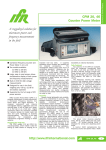
The LI-6262 is a differential, non-dispersive, infrared (NDIR) gas analyzer.
The CO2 and H2O measurements are based on the difference in absorption
of infrared (IR) radiation passing through two gas sampling cells. The
reference cell is used for a gas of known CO2 or H2O concentration, and the
sample cell is used for a gas of unknown concentration. Infrared radiation is
transmitted through both cell paths, and the output of the analyzer is
proportional to the difference in absorption between the two.
Chopping Shutter
Thermoelectric
Cooler
H2O Detector
Lens
H2O Filter
Motor
Thermoelectric
Cooler
Sample
Reference
Lens
Source
Feedback Photodiode
Dichroic Beam
Splitter
CO2 Filter
CO2 Detector
The infrared source is vacuum sealed for long life (> 10,000 hours) and high
stability. A separate optical feedback circuit with a photodiode maintains the
source at a constant color temperature (1250 °K). A gold reflector
surrounding the IR source maximizes the radiation output from the source
and decreases the power required.
The chopping shutter disc is spun by a motor, whose shaft turns on high
precision bearings for long life and low noise. Rotation is precisely
controlled at 500 hertz on a phase locked loop circuit. The optical path
between the source and optical bench is sealed and continuously purged of
CO2 and H 2O by an attached tube containing soda lime and magnesium
perchlorate. This eliminates interference due to ambient CO2 or H 2O vapor.
Theory of Operation
3-1
Section 3
The sample cells are gold-plated to enhance IR reflection and resist
tarnishing over time. One set of sample cells is used for both H2O and CO2
measurements by using a dichroic beam splitter to provide radiation to two
separate detectors.
A 150 nm bandpass optical filter is used to tune the CO2 detector to the 4.26
micron absorption band for CO2, and a 50 nm bandpass optical filter tunes
the H2O detector to the 2.59 micron absorption band. Both filters provide
excellent rejection of IR radiation outside the desired band, allowing the
analyzer to reject the response of other IR absorbing gases. The filters are
mounted directly on the detectors for thermal stability.
Each detector is a lead selenide solid state device that is insensitive to
vibration. The detectors are cooled and regulated to -5 °C by thermoelectric coolers, and electronic circuits continuously monitor and maintain a
constant detector sensitivity. The result of this detector circuitry is a detector
system that is very stable.
Infrared radiation from the source is focused through the gas cells and onto
the detector by a lens at each end of the optical bench. Focusing the
radiation maximizes the amount of radiation that reaches the detector in
order to provide maximum signal sensitivity.
All of these features provide a CO2 noise level that is typically 0.3 ppm
peak-to-peak (at 350 ppm) when using 1 second signal averaging, and 1 ppm
peak-to-peak with 0.1 second signal averaging; the H2O noise level is
approximately 0.002 kPa at 2.0 kPa when using 1 second signal averaging,
and 0.006 kPa when using 0.1 second signal averaging. Signal averaging
times are selectable (in software) between 1 and 30 seconds and are used to
achieve even lower noise levels. For example, with 4 seconds of signal
averaging, the noise levels typically decrease 50%.
3.2 Calculating Gas Concentration - General
LI-COR gas analyzers use a lead selenide detector that operates
approximately as a linear quantum counter; that is, over much of its range
the detector signal output ν is proportional to the number of photons
reaching the detector. The output voltage V that is used to compute CO2
mole fraction is proportional to the difference between the signals generated
by the detector when it sees the sample cell (νs) and when it sees the
reference cell (νr).
3-2
Theory of Operation
Section 3
V = k(νr - ν s)
3-1
The analyzer operates in such a way as to keep νr constant, so we can factor
νr out of the quantity in parentheses, define K = kνr, and obtain,
V = K1 −
υs
υ r
3-2a
In absolute mode, the instrument is operated with no CO 2 in the reference
cell so νr is proportional to maximum photon throughput. The sample cell
normally contains CO2, which reduces the photon flux reaching the detector
through the sample cell and reduces ν s. Therefore, the ratio νs/νr gives the
ratio of photon flux in the presence of CO2 and in its absence, which is just
the transmittance τ. Since absorptance A equals 1-τ, we can also write
equation 3-2 as
V = K(1 - τ)
3-2b
and
V = KA
3-2c
The constant K is given on the calibration sheet.
Equation 3-2c indicates that the analyzer output voltage is proportional to
absorptance; however, absorptance is a non-linear function of CO2 mole
fraction. Absorptance and analyzer output voltage both increase with
increasing CO2 mole fraction in the sample cell. Figure 3-1 illustrates a
typical relationship between gas concentration, transmittance (νs/νr) and
analyzer output voltage.
(A)
νs 1.0
νr 0.8
0.6
0
(B)
Gas Conc.
1.2
Gas Conc.
F(V)
V= K(1- τ)
0
V (volts)
Figure 3-1. (A) The ratio of detector output while viewing the sample cell (νs) and
the reference cell (νr) decreases with increasing gas concentration. (B) The output
voltage V is related to the ratio of νs to ν r by Equation (3-2a). Gas concentration in
terms of V is the calibration function F(V).
Theory of Operation
3-3
Section 3
The factory calibration of the analyzer consists of measuring the output V at
several gas concentrations, and determining the coefficients for a fifth order
polynomial (H 2O uses a third order polynomial) F(V) that relates V to gas
concentration, with a zero gas concentration in the reference cell.
F(V) = a 1V + a2V2 + a3V3 + a4V4 + a5V5
3-3
Coefficients a1 thru a5 are factory-determined for the specific gas, and are
unique to each analyzer. The calibration function F(V) is only valid for the
temperature and pressure at which it was determined, and a zero gas
concentration in the reference cell. It has been found empirically that
(absolute) temperature affects the gas concentration in a linear fashion, while
pressure affects the signal output V in a linear fashion. Therefore, the
expression relating signal output to gas concentration with a zero gas
concentration in the reference cell (absolute mode) is
P T
C = F V o
P To
3-4
where P is barometric pressure in the cell (kPa), Po is standard barometric
pressure (101.3 kPa), T is IRGA temperature (°C or °K), and To is IRGA
calibration temperature (°C or °K).
The situation is a little more complicated in differential mode. If we place a
nonzero CO2 mole fraction in the reference cell, then infrared radiation will
be absorbed, transmittance will decrease, and νr should decline. This decline
is prevented however, by an automatic gain control circuit that increases the
detector gain by an amount necessary to hold ν r constant. This provides
span stability over the long term, but the ouput voltage must now be
corrected for the gain increase before the calibration polynomial can be
applied.
How much is this gain increase? The detector output signal ν r is
proportional to photon flux, so to hold v r constant, the gain must be inversely
proportional to the reduced photon flux that results when CO2 is added to the
reference cell. Transmittance is proportional to the photon flux, so the gain
increase is proportional to 1/ τr, where the subscript r refers to the
transmittance of the reference cell. Therefore, to correct for the gain
increase, we find the transmittance of the reference cell given the reference
cell CO2 mole fraction, and multiply the analyzer output voltage by τr.
To find τr, we assume that the sample and reference cells are optically
identical when they contain the same absorbing gas concentrations. If the
3-4
Theory of Operation
Section 3
two cells are identical, then for a given gas concentration, the transmittance
will be the same whether it is computed against zero between the cells or
within either cell.
Now, suppose the reference cell contains CO 2 mole fraction Cr . If we can
compute what the transmittance would be if Cr were in the sample cell
against zero in the reference cell, then we will know what the transmittance
actually is in the reference cell when it contains C r , and that will tell us how
to correct for the gain change.
The strategy for accomplishing this is straightforward. First, we use Cr to
solve equation 3-4 for Vr , giving
T P
Vr = F −1 C r o
T Po
3-5
Then, rearrange equation 3-2b to find τr given Vr,
V
τr = 1− r
K
3-6
Equations 3-5 and 3-6 ordinarily apply to the situation where Cr is in the
sample cell and zero is in the reference cell; but if the cells are identical, τr
also computes the transmittance in the reference cell when Cr is present. The
gain correction G equals τr, as shown earlier, so
V
G = 1− r
K
3-7
After correcting the differential voltage V for the gain change we can write
GV = Vs - Vr . Solving for Vs and substituting the result into equation 3-4
gives the general expression for computing the gas concentration C in the
sample cell given concentration Cr in the reference cell,
P T
C = F (VG + Vr ) o
P To
3-8
The differential CO2 mole fraction ∆C is simply (C - Cr).
P T
∆C = F (VG + Vr ) o − C r
P To
3-9
Theory of Operation
3-5
Section 3
In this section we have assumed that the sample and reference cells are
optically identical. Strictly speaking, of course, that is not true. This can be
illustrated by setting zero with zero gases in both the sample and reference
cells and then placing a single span gas in both cells. A small zero offset
will usually be observed, illustrating any minor optical differences between
the cells that may exist. Nevertheless, the treatment given here works very
well in practice. Small optical anomalies of whatever origin can be
corrected empirically by setting zero and span.
3.3 Calculating CO2 Concentration
Mole fraction CO2, C (µmol/mol, displayed using FCT 22) comes directly
from equation 3-8. The reference concentration value Cr (µmol/mol), should
be entered via FCT 59. If the reference air is not dry then cr should be the
actual CO2 mole fraction in the presence of water vapor. See sections 3.5
and 3.6.
CO2 differential ∆C, µmol/mol (FCT 23) is C - Cr.
CO2 partial pressure pc (Pa, displayed using FCT 24) is computed from C
and total pressure P (kPa) by
pc =
cP
1000
3-10
The CO2 weight fraction cg (µg/g, displayed at FCT 26) is computed as
Cg =
44c
M
3-11
where M = molecular weight of air (g/mol), weighted for water vapor.
= 29(1 - w/1000) + 18w/1000
w = mole fraction of water vapor (mmol/mol).
3.4 Calculating H2O Concentration
The calculation of water vapor w (mmol/mol, displayed using FCT 32) is
performed using an equation similar to equation 3-8. However, we have
found that the pressure dependence is different from that used in equation 312. We have found empirically that Po/P) 0.9 gives more accurate pressure
correction than Po/P. Thus,
3-6
Theory of Operation
Section 3
0.9
P T + 273
w = Fw (VG + Vr ) o
P To + 273
3-12
and
T + 273 P
Vr = Fw −1 w r o
T + 273 Po
−0.9
3-13
For computational speed, we make the following approximation:
Po
P
0.9
P
≅ o 0.8845 + 0.1089
P
3-14
Vapor pressure e (kPa, FCT 38) is computed from the water vapor mole
fraction w and total pressure P (kPa).
e=
wP
1000
3-15
The dewpoint temperature T d (°C, FCT 38) is computed from an equation
that was fit to the data of Goff and Gratch (1946), as given by List (1966),
giving saturation vapor pressure as a function of temperature over a range of
-50 to 50 °C:
Td =
242.62z
7.6448 − z
where z = log10
3-16
e
.61083
and e is vapor pressure in kPa.
The LI-6262 computes the water vapor weight fraction wg (mg/g, FCT 36)
as
wg =
18w
M
3-17
where M is given after equation 3-12.
Theory of Operation
3-7
Section 3
3.5 Pressure Broadening Due to Water Vapor
Water vapor can influence infrared detection of CO 2 in three ways:
1) direct absorption in the CO2 waveband of interest, 2) dilution, and 3)
pressure broadening. Direct infrared absorption by water vapor can be
virtually eliminated by judicious choice of wavebands and filters, and
methods to correct for dilution are well known (Section 3.6); however,
pressure broadening is more of a problem.
Gas phase absorption of infrared radiation is due to energy-induced changes
in vibrational and rotational energy states. Such energy states are altered by
intermolecular collisions which increase in number as pressure increases.
The kinetic theory of gases and quantum mechanics predicts that absorption
band widths increase with pressure, and it is observed that broad band
infrared absorption increases as pressure increases at constant absorber
concentration.
Not all gases are equally effective in causing pressure-induced line
broadening. Gases that are similar are more effective than dissimilar gases.
This effect is embodied in the concept of equivalent pressure, or effective
pressure, Pe. Total pressure P is equal to the sum of partial pressures of
component gases, while equivalent pressure is defined as
P e = a1p1 + a2p2 + ...
where ai are weighting factors representing the pressure broadening
effectiveness of each gas species relative to nitrogen (aN2 = 1). For CO2 in
nitrogen Pe = p N2 + 1.3 p CO2 (2).
Consider a simple atmosphere made up of H2O vapor with pressure e, plus
dry gases with pressure P d, so that
P = Pd + e,
or, in mole fraction units,
1 = Xd + Xw
3-18
where X d is the mole fraction of all dry gases and Xw is the water vapor
mole fraction (e/P).
The equivalent pressure will be Pe = Σaip i + awe. In principle, Pe will vary
with CO2 partial pressure, but the CO2 partial pressure is so small that it can
3-8
Theory of Operation
Section 3
be neglected. Thus, if other atmospheric components are constant, an
equivalent pressure can be defined as
P e = adP d + awe
= P(adXd + a wXw)
3-19
where Pd is the total pressure of dry air, and ad is a dry air weighting factor.
LI-COR calibrates all of its analyzers using CO2 or water vapor in air, so
ad = 1 is taken as the standard condition. Substituting equation 3-18 into
equation 3-19 gives
P e = P[1 + (aw - 1)Xw]
3-20
The value of aw is not an intrinsic constant comparable to other such values
in the literature because it uses dry air as a reference instead of nitrogen. Its
value has been empirically determined to be about 1.5 against dry air. The
value of aw used in 3-20 is entered into the LI-6262 using FCT 78.
Equation 3-20 can be extended to include nitrogen as standard, and both
water vapor and oxygen (or other gases) as variable components. Pe can be
written in a more general form to anticipate that possibility:
P e = P[1 + (aw - 1)Xw + Σ(bi - 1)Xi]
3-21
For the present, equation 3-20 is implemented in the LI-6262 software;
equation 3-21 has not yet been tested. Equation 3-20 can be compactly
rewritten as
P e = Pχ(Xa)
3-22
where χ(Xa) = 1 + (aw - 1)Xa , and then incorporated into the COa calibration
function.
The form of the CO2 calibration function (equation 3-4) was derived
empirically, but it can also be derived from a "scaling law" called the "nonoverlapping line approximation" which holds when absorber concentrations
are low or pathlengths are short (4). This “scaling law” allows absorption
measured under one set of conditions to be scaled to other conditions (2),
A
= g( u / P )
P
3-23
Theory of Operation
3-9
Section 3
where A is total band absorption, P is total pressure (kPa), u is absorber
amount (mol m-2 ) = ρL; ρ is mol density (mol m-3 ), and L is pathlength (m);
g is a general unspecified function.
From the ideal gas law, the absorber mole density ρ can be expressed as
ρ=
p
RT
=
XP
RT
3-24
where ρ is absorber partial pressure and X is absorber mole fraction (mol
absorber/mol air). Therefore,
u XL
=
P RT
3-25
Substituting equation 3-25 into 3-23 and incorporating the constants L and R
into a new function h gives
A
X
= h
T
P
3-26
In principle, equation 3-26 can be solved for mole fraction, giving
A
X = h −1 T
P
3-27
Since LI-COR gas analyzers produce an output voltage that is proportional
to absorptance,
V=KA
3-28
substituting 3-28 into 3-27 yields
P T
C = F V o
P To
3-29
where C is the CO2 mole fraction in µmol mol-1, and the constants K, Po and
To are included in the general function F; Po = 101.3 kPa, and To is the
calibration temperature in degrees Kelvin. Equation 3-29 is the fundamental
3-10
Theory of Operation
Section 3
LI-COR gas analyzer calibration function, where F(x) is a polynomial. By
substituting equation 3-22 into 3-23 and following through the derivation,
the calibration equations for CO2 become:
c r T + 273 P
Vr = χ(w r )F −1
χ(w r ) To + 273 Po
V
G = 1− r
K
3-30
VG + Vr Po T + 273
C = χ( w s ) F
χ(w s ) P To + 273
∆C = C - Cr
The water correction is based upon a theoretically justifiable procedure
which requires determination of a single physically meaningful constant, and
can be applied to any LI-COR 6200 series infrared gas analyzer, and perhaps
others, as well.
3.6 Dilution Corrections
A dilution correction can be applied in the LI-6262, if desired. When one
component gas of multicomponent mixture is decreased at constant pressure,
the partial pressures of all other components are increased accordingly. For
example, if water vapor is removed at constant pressure, then the partial
pressures of other components increase according to
P=
∑ p i wet
(1 − w / 1000)
3-31
where w is the water vapor mole fraction (mmol/mol) and the p wet are
i
partial pressures of other component gases before water vapor was removed.
For individual components, Equation 3-31 becomes
p i dry =
p i wet
(1 − w / 1000)
3-32
Theory of Operation
3-11
Section 3
It is often necessary to correct the CO2 mole fraction for differences in water
vapor mole fraction in sample and reference cells when CO2 and water vapor
are measured together. An apparent CO2 mole fraction difference will
develop if water vapor is added to or removed from either air stream whether
a net CO2 flux is present or not. This dilution effect can be removed when
the Vapor Flag (FCT 76) is set to BndBrd, Dil → Ref; the CO2 mole
fraction in the sample air stream is then corrected to the water vapor mole
fraction that is in the reference air stream according to
C s wr = C s ws
(1 − w ref / 1000)
(1 − w / 1000)
3-33
C sws is the actual CO2 mole fraction in the sample cell diluted by w, and cswr
is the equivalent sample cell CO2 mole fraction if it were diluted by wref.
It is important to distinguish the different water corrections that can be
applied in the LI-6262. The Vapor Flag (FCT 76) can be in one of three
states:
0 - Corrections Off: No pressure broadening or dilution corrections are
applied.
1 - Band Broadening: A pressure broadening correction is applied, but no
dilution correction is performed. The actual CO2 mole fraction in the sample
cell or the actual CO2 differential is displayed.
2 - BndBrd, Dil → Ref: Both a pressure broadening and a dilution
correction are applied. The sample cell CO2 mole fraction and the CO2
differential are corrected for differences in sample and reference air stream
water vapor contents. This is the appropriate setting for photosynthesis
measurements. NOTE: This is the default setting when the system is
configured at the factory, or when the system is reset (FCT 08).
3.7 Cr is Unknown. Measuring Cr against Cs = 0
Sometimes a CO2 differential must be measured when the reference CO2
mole fraction is not precisely known. For example, one might be measuring
photosynthesis in the field with ambient air as the reference gas, the exact
CO2 mole fraction of which is not known. One could scrub the reference
cell and measure the incoming CO2 concentration in absolute mode.
However, there will be a small zero shift when the reference gas is reduced
from around 350 ppm to 0 ppm, so a zero adjustment must be made each
3-12
Theory of Operation
Section 3
time the reference cell is scrubbed. The same is true when ambient air is
returned to the reference cell.
It is easier to leave the reference gas alone and scrub the sample cell; this
avoids zero shifts and gain changes. One can then measure the output
voltage V and compute Vr and Cr according to equations 3-34 and 3-35.
Vr =
−V
V
1−
K
3-34
P T + 273
C r = F Vr o
P To + 273
3-35
These values can be used as needed to compute Cs or ∆C over as long a time
period as Cr and temperature are stable. Note: This is not implemented in
the instrument, but is provided as an aid to those needing this trick.
Theory of Operation
3-13
Section 3
References
1.
Goff, J.A., and S. Gratch, 1946. Trans. Amer. Soc. Heat. and Vent.
Eng., Vol. 52, p. 95.
2.
Jamieson, J.A., et.al. 1963. Infrared Physics and Engineering.
McGraw-Hill, New York, N.Y. p. 65.
3.
List, R.J. 1966. Smithsonian Meteorological Tables, 6th rev. ed. The
Smithsonian Institution, 527 pp.
4.
Wolfe, W.L., and G.J. Zissis. 1978. The Infrared Handbook. Office of
Naval Research, Department of the Navy, Washington, D.C.
3-14
Theory of Operation
LYZER
ZERO
CO2/H2O ANA
SPAN
ZERO
2
3
FUNCTION
4
5
6
EEX, ↑
8
9
↓
7
0
.
ENTER
C
1
62
Model LI-62
CO2
SPAN
ON
H2O
®
READY
OFF
4
Calibration
4.1 Calibration - General Information
The factory calibration of the LI-6262 CO2/H2O Analyzer consists of
determining the coefficients for the calibration polynomials for CO2 and
H2O. These coefficients should be quite stable over time, but we
recommend that they be checked every two years by returning the LI-6262 to
LI-COR for recalibration.
The user calibration consists of adjusting the zero and span potentiometers so
that the analyzer's output matches the linearization polynomial F(V). This
should be done on a daily basis (unless the 6262-03 Pressure Transducer
is installed), as the span varies with barometric pressure, and the zero
varies with temperature.
Figure 4-1 illustrates the effects of the zero and span adjustments.
1000
SPAN SHIFT
C(ppm)
ZERO SHIFT
0
5
V (volts)
Figure 4-1. Effects of zero and span adjustments.
Procedures for zero and span calibrations are given in Section 4.2 for
differential mode operation and in Section 4.3 for absolute mode operation.
Calibration
4-1
Section 4
4.2 Differential Mode Calibration
It is important to remember that in differential mode the pressures on the two
sides of the analyzer must be kept the same. For this reason, never connect
the exit ports ( SAMPLE OUT and REFERENCE OUT) to anything - just vent
them to the atmosphere, or to tubes of equal length. If you wish to flow the
same gas through both sides of the analyzer, try to avoid doing it by putting
the sample and reference cells in series, as you will likely have different
pressures. Instead, split the flow upstream of the analyzer, and run separate
hoses to the reference and sample cells. Also, be sure the flow rates through
both sides are the same.
The concentrations used to set the zero and span should bracket the range of
concentrations expected in subsequent measurements. For example, using
340 ppm for the zero and 300 ppm for the span might be the proper
selections for flow-thru photosynthesis applications where drawdowns from
ambient are expected.
There is generally a small zero shift when the reference concentration
changes. Therefore, if operating in a mode in which there are significant
changes in reference gas concentration, you should re-zero the analyzer
following each change in concentration.
CO2 Zero and Span Calibration
1.
Set the CO 2 reference to zero (FCT 59). If you are not using the
6262-03 Pressure Transducer, enter the barometric pressure in FCT 77.
2.
Display absolute CO2 µmol/mol (FCT 22).
3.
Flow a dry CO2-free gas through both sides of the analyzer.
4.
Unlock the CO2 zero potentiometer and adjust until the absolute CO2
concentration on the display reads zero.
5.
With the CO2-free gas on the reference side, flow a span gas through the
sample cell. Set the span potentiometer to read the span gas mole
fraction (µmol/mol).
6.
Flow the span gas through both cells of the analyzer at the same flow
rate. The flow rate should match that used in the reference cell. Set the
CO2 reference (FCT 59) to the span gas mole fraction (µmol/mol).
Display differential CO2 (FCT 23).
4-2
Calibration
Section 4
7.
There will likely be a small zero offset. Adjust the zero potentiometer to
read zero.
8.
To check the span, flow a different gas through the sample cell. FCT 22
should show that value. If you don’t have a second gas, you could scrub
the sample cell, and see if FCT 22 reads zero. Adjust the span as
needed.
9.
Lock the potentiometers.
H2O Zero and Span Calibration
It is likely that zero and reference gases containing known amounts of water
vapor will be produced by a dewpoint generator, such as the LI-610, or
measured with a dewpoint hygrometer. However, the LI-6262 requires that
the reference cell water vapor mole fraction be entered as a parameter before
differential measurements can be performed. Therefore, it will often be
necessary to convert a dewpoint temperature into a vapor pressure, and then
into mole fraction.
Vapor pressure can be obtained from dewpoint temperature by making
reference to Appendix F, or by calculation. Note that Appendix F gives
vapor pressure in millibars; these values must be divided by 10 to convert to
kilopascals.
Vapor pressure e (kPa) can be calculated as
7.6448 Td
e = 0.61083 × 10
242.62 + Td
where Td is the dewpoint temperature. The reference water vapor mole
fraction (mmol/mol) is
Wref = 1000
e
p
where P is the local barometric pressure in kilopascals. See Section 3.4 for
further information.
Calibration
4-3
Section 4
The H2O zero and span calibration is identical to that for CO2; however,
allow adequate time for equilibration (several minutes after changing the
humidity).
1.
Set the H2O reference to zero (FCT 68). If you are not using the
6262-03 Pressure Transducer, enter the barometric pressure in FCT 77.
2.
Display absolute H 2O (FCT 32, 34, or 36).
3.
Flow a dry gas through both sides of the analyzer.
4.
Unlock the H2O zero potentiometer and adjust until the absolute H2O
concentration on the display reads zero.
5.
With a dry gas on the reference side, flow a span gas through the sample
cell. Set the span potentiometer to read the value of the span gas in the
appropriate units.
6.
Flow the span gas through both cells of the analyzer, at the same flow
rate. Set the H2O reference (FCT 68) to the value of the span gas in the
appropriate units. Display differential H2O (FCT 33, 35, or 37).
7.
There will likely be a small zero offset. Adjust the zero potentiometer to
read zero.
8.
To check the span, flow a different humidity through the sample cell.
FCT 32 (or 34 or 36) should show that value. Adjust the span as needed.
9.
Lock the potentiometers.
4-4
Calibration
Section 4
4.3 Absolute Mode Calibration
The procedure for setting the zero and span potentiometers in absolute mode
is described in Steps 1 thru 5 above for differential mode calibration.
4.4 H2O Absolute Mode Caution
When using the LI-6262 to measure water vapor in absolute mode, note the
following:
When the LI-6262 is configured as described in Section 2.2 for absolute
operation, air flow created by movement of the chopping shutter disc is
sufficient to purge the reference cell of CO2. This air flow is not, however,
sufficient to remove all water vapor present in the reference cell.
An external pump, such as the 6262-04 Reference Pump from LI-COR (see
Using the 6262-04 Reference Pump below), or the LI-670 Flow Control Unit,
is necessary to provide an adequate flow of dry air through the desiccant
circuit. A flow rate of approximately 500 ml per minute is sufficient to
purge the reference cell.
The flow of dry air through the reference cell and scrubber tube assembly
will also greatly affect the performance and maintenance requirements of the
external soda lime/magnesium perchlorate mixture. An inherent property of
soda lime is that a small amount of water vapor must be present for the
chemical to scrub CO2. Ordinarily, this water vapor is present in the soda
lime due to normal diffusion through the air hoses; however, Mg(ClO4)2
reduces the airstream water vapor concentration to near zero. Prolonged
exposure of the soda lime to dry air reduces its ability to scrub CO2.
It is therefore recommended that the external soda lime/desiccant be
replaced every 1-2 days when operating the LI-6262 for absolute H2O
measurements. If this is a problem, an alternative is to maintain a low flow
of CO2-free air from a compressed tank that goes through the chopper and
reference cell and is then vented to the atmosphere.
Calibration
4-5
Section 4
Figure 4-2 shows one way in which the LI-6262 may be set up with an
external pump providing air flow through the reference cell circuit. The
arrows indicate the direction of air flow through the analyzer. It is
recommended that the pump be placed inline between the FROM CHOPPER
fitting and the scrubber tube assembly, rather than between the scrubber tube
and the REFERENCE IN fitting. Pulling air from the scrubber tube assembly
could cause damage to your pump and/or analyzer if, by chance, the paper
filter disc in the scrubber tube was torn, causing magnesium perchlorate to be
pulled into the system.
Filter
Mg(ClO4)2
SAMPLE
IN
REFERENCE
IN
TO
CHOPPER
FROM
CHOPPER
SAMPLE
OUT
REFERENCE
OUT
SODA
LIME
PUMP
Figure 4-2. Configuration of LI-6262 with external pump for operation in H 2 O
absolute mode.
Using the 6262-04 Reference Pump
The 6262-04 pumps approximately 0.22 to 0.5 liters of air per minute, which
is sufficient to purge the reference cell. The 6262-04 flow rate can be
adjusted with the screwdriver included, by turning the Flow Adjust
potentiometer clockwise to increase the flow, or counterclockwise to
decrease the flow.
Please note also that there is no internal filter ahead of the reference cell.
Make sure that the paper filter disk in the soda lime/desiccant tube is not
torn, as magnesium perchlorate can be forced into the reference cell,
damaging the analyzer. Alternatively, you can place an external filter
between the soda lime/desiccant tube and the Reference In fitting.
■
A Phillips head screwdriver is required for installation. Follow these
steps to install the 6262-04 Reference Pump:
1.
Remove the soda lime/desiccant tube mounting clips from the back of
the LI-6262.
4-6
Calibration
Section 4
2.
Remove the 8 screws from the top and bottom of the 6262-04 cover.
3.
Attach the 6262-04 cover to the analyzer using the 2 screws from the
mounting clips. The screws are inserted into the holes where the
mounting clips were previously attached.
4.
Attach the 6262-04 to its cover by replacing the 8 screws.
5.
Screw the soda lime/desiccant tube mounting clips into the rear face
plate of the 6262-04. Attach the soda lime/desiccant tube.
6.
Plug the battery cable from the 6262-04 into the battery jack on the
analyzer.
7.
Attach the hoses:
Mg(ClO4 )2 → REFERENCE IN fitting (LI-6262)
Soda Lime → TO SCRUB fitting (6262-04)
TO CHOPPER fitting (LI-6262) → REFERENCE OUT fitting
(LI-6262). (This tube is threaded through the 6262-04).
FROM CHOPPER fitting (6262-04) → FROM CHOPPER fitting
(LI-6262)
The finished assembly will look similar to that shown in Figure 4-3
below.
8.
Plug battery into the battery jack on the 6262-04, or connect a power
cord to the LI-6262 if using AC power. Important Note: The 6262-04
Reference Pump must be turned off independently; it will not shut off
when the LI-6262 is powered off.
9.
Turn on the pump.
Calibration
4-7
Section 4
Figure 4-3. 6262-04 Reference Pump installed on LI-6262 back panel.
4-8
Calibration
Section 4
4.5 Pressure Corrections
NOTE: This section may be disregarded if the 6262-03 Pressure Transducer
is installed.
The LI-6262 is sensitive to pressure differences between the sample and
reference cells. The span of the analyzer should be set with a span gas flow
rate equal to the flow rate at which it will be used. With the flow of the
analyzer vented to the atmosphere the effect is minimal, but if the flow from
the analyzer must pass through tubing, fittings, etc., the pressure increase
must be taken into account.
If it is not convenient or possible to have the span gas flow rate equal to the
flow rate used during measurement, the pressure effect can be characterized,
and the span set at zero flow, after complete purging of the sample cell. The
procedure for this is as follows:
1.
Connect a stable source of air to the input of the analyzer, and adjust the
flow rate to be equal to the flow rate at which measurements will be
taken.
2.
Monitor CO2 or H2O on the display, and record the concentration after
the reading has stabilized.
3.
Shut the flow off, leaving this same concentration in the sample cell.
4.
Record the concentration from the display.
Correction factor = Conc. (with flow)/ Conc. (without flow)
When setting the span, multiply the reading obtained without flow by the
correction factor, and set the displayed concentration equal to the corrected
value.
This flow/concentration relationship is linear over the entire measurement
range of the LI-6262. If another flow rate is used, a new correction will have
to be calculated.
4.6 Setting the Zero and Span in Software
FCT 08 (Test Menu) contains CO2 and H2O Zero/Span functions that
provide a software method of setting the zero and span without manually
adjusting the potentiometers. There are two advantages of allowing software
zero and span adjustments; the zero and span can be set using a remote
Calibration
4-9
Section 4
command sequence, and the user can get the analyzer back “on scale”
through software if the zero and/or span has gone beyond the range of the
potentiometer.
The zero and span parameters initially default to these values:
H2 Zero = 0.0 (mV offset)
H2 Span = 1.0 (dimensionless)
C2 Zero = 0.0 (mV offset)
C2 Span = 1.0 (dimensionless)
When these default values are in effect, no software zero or span adjustments
are performed.
When the H2 Zero and H2 Span values are changed, the mV signal normally
used in the calculation of H2O concentration (FCT 31) is transformed
according to
H2O mVnew = (H2 Span) × (mV - [H2 Zero]).
When the C2 Zero and C2 Span values are changed, the mV signal normally
used in the calculation of CO 2 concentration (FCT 21) is transformed
according to
CO2 mVnew = (C2 Span) × (mV - [C2 Zero]).
The values of CO 2 mVnew and H2 O mVnew are used by the calibration
polynomials to compute concentration, but do not change the raw CO2 mV
signal displayed at channel 21, or the raw H2O mV signal displayed at
channel 31, or the output (RS-232C) values of either.
The values of H2 Zero and H2 Span, and C2 Zero and C2 Span can be
entered via the keypad at FCT 08, or by sending a remote command
sequence. When sending a remote command, you have the option of
entering the Zero and Span values, or allowing the analyzer software to
calculate the values for you. The following examples demonstrate how you
can calibrate your LI-6262 in software for both absolute and differential
measurements.
Remote Commands
The remote command sequence for the CO2 software zero and span is
4-10
Calibration
Section 4
*081,C2 Zero,C2 Span,CO2 concentration (µmol/mol).
The remote command sequence for the H2O software zero and span is
*082,H2 Zero,H2 Span,H2O concentration (mmol/mol).
The last parameter (CO2 or H2O concentration) is optional, and is used only
when you want the software to compute the zero or span value. If the
concentration is set to zero, the software computes the zero offset and stores
it as C2 Zero or H2 Zero. When zero is entered, you must have the same gas
concentration flowing to both the sample and reference cells of the analyzer.
If any value other than zero is entered, the software computes the
dimensionless span value for that concentration as
Span = Vcalc / Vmeas = F-1 (Span To/T)/Vmeas.
NOTE: The LI-6262 will not accept remote commands while the Test
Menu is active. Exit the Test Menu and enter display mode; the remote
command will then be executed.
Absolute Mode Calibration
1.
Set the CO2 zero.
● Flow CO 2-free air through the chopper housing, reference, and
sample sides of the analyzer.
● Send remote command *081,0,1,0 to set the zero.
2.
Set the CO2 span. Let’s assume that we are using a 500 ppm span gas.
● Flow CO2-free air through the chopper housing and reference side
of the analyzer.
● Flow 500 ppm span gas through the sample side of the analyzer.
● Send remote command *081,0,1,500 to set the span.
Differential Mode Calibration
Assume for this example that we are using precision span tanks of 300 and
500 ppm CO 2.
1. Set the CO2 zero.
● Flow CO2-free air through the chopper housing, and the 300 ppm
gas through the reference and sample sides of the analyzer.
● Send remote command *081,0,1,0 to set the zero.
Calibration
4-11
Section 4
●
2.
Set FCT 59 (CO2 reference) to 300.
Set the CO2 span.
● Flow CO2-free air through the chopper housing.
● Flow 300 ppm span gas through the reference side of the analyzer.
● Flow 500 ppm span gas through the sample side of the analyzer.
● Send remote command *081,0,1,500 to set the span.
The procedure for setting the H 2O zero and span is identical to the above
steps, with the exception that the air must be completely dry to set the zero,
and the span is set using an airstream containing a known water vapor
concentration, as can be provided by the LI-610 Portable Dewpoint
Generator, for example.
4.7 Using the LI-670 Flow Control Unit
The LI-670 Flow Control Unit can be a valuable accessory for operating and
calibrating your LI-6262. The following discussion describes how you can
calibrate your LI-6262 using the LI-670 and a single span gas.
Absolute and Differential Mode Calibration with One Span Gas.
Absolute mode. Set zero.
1. Connect the LI-6262 Sample In fitting to the LI-670 Sample Out fitting,
and the LI-6262 Reference In fitting to the LI-670 Reference Out
fitting.
2.
Enter the station barometric pressure into the LI-6262 at FCT 77.
Alternatively, you can use the 6262-03 Pressure Transducer, or an
external sensor to input the barometric pressure.
3.
Connect a span tank containing air (not nitrogen) with a known H2O or
CO2 mole fraction to the LI-670 Sample In and Reference In fittings,
and turn both the reference and sample CO2/H2O Scrub switches ON.
Use tank pressure to provide flow at a nominal rate near that used during
measurements. Final flow rate adjustments can be made with the
LI-670 SAMPLE and REFERENCE vents.
4.
When the reading is steady, adjust the zero potentiometer on the LI-6262
until the display reads zero.
4-12
Calibration
Section 4
Sample
Sample
In
Aux.
Ports
Diff.
Zero
CO2/H2O
Scrub
Reference
In
Ref.
Swap
CO2/H2O
Scrub
LI-670
Scrub both cells.
Absolute mode. Set span.
5. Turn OFF the S A M P L E C O2/H2O Scrub switch.
Leave the
REFERENCE CO2/H2O Scrub switch ON. Adjust the flow as needed.
6.
Set the LI-6262 span when the displayed reading is steady.
Sample
Sample
In
Aux.
Ports
Diff.
Zero
CO2/H2O
Scrub
Reference
In
LI-670
Ref.
Swap
CO2/H2O
Scrub
Scrub only the reference cell.
The LI-6262 is now ready for use in absolute mode. Differential mode
operation requires three additional steps.
Differential mode. Set zero.
7. Perform steps 1 through 6, and then turn OFF the R E F E R E N C E
CO2/H2O Scrub switch. Adjust the flow to near that which will be used
during measurements.
8.
Adjust the LI-6262 to read zero when the displayed mole fraction is
steady. Only a small adjustment should be necessary (about 5 ppm)
when switching from zero to 350 ppm in the reference cell.
9.
Enter the span gas CO2 mole fraction in FCT 59, or the span gas H2O
mole fraction in FCT 68 in the LI-COR analyzer. Read differential H2O
or CO 2 on the analyzer display. Check the span by scrubbing the sample
cell and looking for zero on FCT 22 or FCT 32.
Calibration
4-13
Section 4
Sample
Sample
In
Aux.
Ports
Diff.
Zero
Reference
In
LI-670
CO2/H2O
Scrub
Ref.
Swap
CO2/H2O
Scrub
Scrub the sample cell.
The LI-6262 zero or span can be checked during measurements by
turning ON the Diff Zero switch, and then using whichever scrubbers are
needed.
Sample
Sample
In
Aux.
Ports
Diff.
Zero
Reference
In
LI-670
CO2/H2O
Scrub
Ref.
Swap
CO2/H2O
Scrub
Flow the span gas through both cells of the analyzer.
Many other calibration variations are possible. For example, you may want
to recirculate air in a closed reference loop for absolute mode operation.
4-14
Calibration
LYZER
ZERO
CO2/H2O ANA
SPAN
ZERO
2
3
FUNCTION
4
5
6
EEX, ↑
8
9
↓
7
0
.
ENTER
C
1
62
Model LI-62
CO2
5
SPAN
ON
H2O
®
READY
OFF
System
Software
5.1 Using the Keypad
The LI-6262 uses a 16-key keypad for entering all software function
commands and calibration data. The keys are arranged as in Figure 5-1, and
function as follows:
1
2
3
FUNCTION
4
5
6
EEX
7
8
9
↓
C
0
.
ENTER
↑
Figure 5-1. The LI-6262 Keypad.
Numeric keys (0-9) and decimal key - Used to enter software function
codes and calibration numbers.
Function key - Function prompt is accessed, allows user to enter any
software function command #00-99.
Exponent/Scroll Up key - Used to enter exponents (i.e, when entering CO2
or H2O calibration numbers), or to scroll upward through option lists.
Minus/Scroll Down key - Used to enter a negative number sign, or to scroll
downward through lists.
Enter key - Used to terminate user input from the keypad after entering
numbers, or to select list entries.
Clear key C - Functions as a backspace key, deletes last character.
System Software
5-1
Section 5
5.2 Software Overview
All software commands are executed by pressing FUNCTION and then
entering a two-digit function code. Some codes execute a function directly,
while others access scrollable lists of options, or other functions, any one of
which can be selected by pressing ENTER.
All functions are contained in the main menu, by order of function code.
Decade functions (00, 10, 20, ...90) merely serve as entry points to this
menu. For example, pressing FCT 10 will access the menu at 10, from
which point ↑ or ↓ can be used to scroll to neighboring functions. On the
other hand, pressing FCT 11 does not access the menu, but executes function
11 directly. Rapid scrolling down through the menu is done by pressing
ENTER, while viewing a decade function; you will jump to the next decade
function (e.g. from 10 to 20) in the menu.
To illustrate the use of the FUNCTION key and the main menu, try this:
1. Press FCT 90. The display will show the main menu at 90 as **DISP**.
2. Press ↓ to move down one entry to function 91.
3. Press ENTER. This will select function 91, which shows the channel
code that is currently defined for the top line of display #1, and prompts
for a new value.
4. Press ENTER to retain the displayed value. You are prompted to enter a
channel code for the bottom line of display #1. Press Enter again to
retain the displayed value. Note that the display has returned to the
menu.
5. Press ↑ to scroll up to function 90, **DISP**.
6. Press ENTER . Selecting a decade function jumps to the next decade
function, so the display will show 00, **SETUP**.
7. Press FUNCTION to exit the menu.
8. Press FCT 91. This will directly execute the function described in step 3
above, which prompts for a new channel code for the top line of display
#1.
9. Press ENTER to retain the displayed value of this constant, or press
FUNCTION to cancel the operation.
5-2
System Software
FCT 00
Remote Commands
Certain function codes can be sent to the LI-6262 from a computer or
terminal, as shown on the console command card.
Section 6.2 gives a complete explanation of how to connect your
computer and LI-6262 for data transfer and for sending remote
commands. Look for the icon at left in the following section for
examples of how to format entries to be sent to the LI-6262.
5.3 Console Commands
This section discusses each function in detail. It may be helpful to reference
the console command summary card while reading through the definitions of
the following functions.
00 Setup
00** SETUP **
↑,↓,↵
Scroll ↑
or
(UP), ↓ (DOWN),
ENTER.
System Software
5-3
FCT 01
01 CO2 Calibration
Function 01 is actually a group of functions; executing FCT 01 performs
functions 51-59 and 76.
The LI-6262 is calibrated using a 5th order calibration polynomial of the
form: µmol/mol = A(mV) + B(mV)2 + C(mV)3 + D(mV) 4 + E(mV)5. The
calibration coefficients (T,K,A,B,C,D,E) are entered into the LI-6262 at the
factory, and are shown on the calibration sheet.
CO2 reference mole fraction (µmol/mol) and the choice of water correction
depend upon your system setup. See functions 59 and 76 for complete
descriptions.
Check the calibration sheet to verify that the correct values are entered.
Prompt
C2 T=
C2 K=
C2 A=
C2 B=
C2 C=
C2 D=
C2 E=
C2 R=
BandBrd, Dil → REF
Description
Calibration Temperature
Calibration Constant K
Calibration Coefficient A
Calibration Coefficient B
Calibration Coefficient C
Calibration Coefficient D
Calibration Coefficient E
CO2 Reference µmol/mol
Water correction selection
*01T,K,A,B,C,D,E,REF,VAPOR FLAG
5-4
System Software
Related Function
51
52
53
54
55
56
57
59
76
FCT 02-03
02 H2O Calibration
Function 02 performs functions 61-65, and 68.
H2O calibration coefficients (T,K,A,B,C) are factory-entered, and are on the
calibration sheet. H 2O reference mole fraction is in units of millimoles/mole
of water vapor in the reference cell.
Verify these values with the H2O calibration sheet and change, if needed.
Prompt
H2 T=
H2 K=
H2 A=
H2 B=
H2 C=
H2 R=
Description
Calibration Temperature
Calibration Constant K
Calibration Coefficient A
Calibration Coefficient B
Calibration Coefficient C
H2O Reference mmol/mol
Related Function
61
62
63
64
65
68
*02T,K,A,B,C,REF
03 Set Miscellaneous
Function 03 performs functions 71-75 and 77.
Prompt
P(kPa)=
Avg(s)=
Aux A=
Aux B=
Aux C=
Aux Dest=
Description
Barometric Pressure
Signal Averaging Time
Auxiliary Input Coefficient A
Auxiliary Input Coefficient B
Auxiliary Input Coefficient C
Auxiliary Destination
Function
77
74
71
72
75
73
There is no remote command for FCT 03, but all of the 7x functions can be
accessed remotely.
System Software
5-5
FCT 04
04 Set Displays
Function 04 performs functions 91-99.
The LCD display has two lines, and each line can be configured to show any
channel code 21-29 (CO2), 31-39 (H2O), or 41-47 (MISC). As many as nine
two-line display configurations can be defined by the Set Displays routine.
Each display is identified by a number 1 through 9, and can be viewed by
pressing the appropriate number without pressing FCT.
NOTE: Displays 1-6 (FCT 91-96) default to the configurations shown
below at initial power-up or system reset.
Function Codes
(Top/Bottom Lines)
21
22
23
29
41
42
31
32
33
39
43
44
Display
1
2
3
4
5
6
Description
CO2 mV (non-linear)
CO2 µmol/mol absolute
CO2 µmol/mol differential
CO2 µmol/mol reference
Temperature mV
Temperature °C
H2O mV (non-linear)
H2O mmol/mol absolute
H2O mmol/mol differential
H2O mmol/mol reference
Barometric Pressure (kPa)
Auxiliary mV
Set the displays as follows:
Press FCT, followed by 04. The display will show:
1 Top=21
NEW= __
1 Bottom=22
NEW= __
Shows default channel code for
top of display 1. Enter new code
21-29, 31-39, or 41-47.
Default channel code for bottom
of display 1.
Prompts to configure displays 2 through 9 follow. Press FCT to quit.
5-6
System Software
FCT 05-06
05 Set D/A Conversion #1
Function 05 performs functions 81, 82, and 83.
DAC 1 Code=
NEW= __
Digital to analog conversion
code #1.
Digital to Analog Conversions may be performed on channel codes 22-27,
32-38, or 42. See function codes 80 - 83 for further details.
*05X,low,high (where x is channel code 22-27, 32-38, or 42).
06 Set D/A Conversion #2
Function 06 performs functions 84, 85, and 86.
DAC 2 Code=
NEW= __
D/A Conversion #2 (same as
05).
*06X,low,high (where x is channel code 22-27, 32-38, or 42).
System Software
5-7
FCT 07-08
07 Backlight ON/OFF
YES or NO.
BACK LIGHT=NO
↑,↓,↵
Press ↑ or ↓ to toggle the LCD display backlight on or off. Change if
desired, depending on the lighting conditions in your work area. Continuous
use of the backlight may slightly reduce battery operation time.
NOTE: If FCT 07 is executed from the main menu, the backlight
condition does not change until you exit the menu.
*07Y (Yes) or *07N (No).
08 Test Menu
Scrolls through display test
menu.
DISPLAY Test
↑,↓,↵
While most of the items in the Test Menu are for technician use, there are a
few items of interest to many users.
The KBD (Keyboard) Test prompts to press any key; each of the 16 keys
should display correctly when pressed.
The D/A (Digital-to-Analog) Test is used to test the digital to analog
conversion capabilities of the LI-6262. Enter a value (in volts), to be output
to channel 1 or 2, which can be measured with a metering device.
DA1:
NEW= __
5-8
System Software
0.0
Prompt for digital to analog
conversion value (in volts).
FCT 08
The A/D (Analog-to-Digital) Zero Test displays the analog count of output
channels 1 and 2. If the A/D converter is functioning properly, these values
should be nearly identical (approximately 32,700).
The A/D (Analog-to-Digital) Span Test displays the analog count of output
channels 1 and 2, as well as the analog count and actual mV output of the
CO2, Temperature, and Auxiliary output channels.
The RAM (Random Access Memory) Test shows the amount of available
system RAM. The LI-6252 has approximately 8K bytes of RAM.
The EEPROM (Electrically Erasable Programmable Read-Only
Memory) Test shows the amount of available ROM memory. The system
parameters entered by the user are stored in EEPROM. The LI-6262 has
approximately 32K bytes of ROM program memory.
Geopotential - Displays the geopotential height in feet or meters, based on
the current value of pressure at channel 43. This value can be provided by a
sensor (FCT 73) or as a keyboard entered constant (FCT 77). Press the up or
down arrow keys to toggle between units of feet and meters. Geopotential
height is height above sea level in a standard atmosphere.
The I/O (Input/Output) Test checks the Input/Output capabilities of the
RS-232C port. This test requires pins 2 and 3 to be shorted on the RS-232C
connector.
CO2 Zero/Span - Provides a method to set the CO2 zero and span in
software, via the keypad or by sending a remote command sequence. See
Section 4.5, Setting the Zero and Span in Software, for more information.
System Software
5-9
FCT 08
Reset System - The software used in the LI-6262 is also used in the LI-6252
CO2 analyzer. By entering 1 for Yes you can change the configuration to
that of a LI-6252 analyzer. This function is primarily for factory use only, so
ordinarily this should not be changed. Pressing 1 for Yes will remove all
configuration parameters from the analyzer; they will then need to be
re-entered.
Reset System?
1=Yes, 0=No
YES or NO.
Clearing EEPROM...
SYSTEM TYPE
LI-62X2 (5/6)
5-10
System Software
Enter 6.
FCT 09
09 Integrate
This function allows the area under a peak to be computed. When you press
FCT 09, you are prompted for the following parameters:
Prompt
Description
Source Ch=
Channel code of the quantity to be integrated.
Start =
Exit
{On
Thrsh
When to start the integration. ‘On Exit’ will start
the integration immediately. ‘Thrsh’ will start the
integration when the selected channel rises above
the threshold value.
Thrsh= 0.0
If Start=Thrsh was selected above, you are
prompted to enter the starting threshold value.
{
When to stop the integration. ‘Manual’ will cause
the integration to continue until FCT is pressed, or
until a * (asterisk) is received from the remote
terminal. ‘Elaps tm’ (elapsed time) will cause the
integration to run for the specified number of
seconds. ‘Thrsh’ will cause the integration to
continue until the target channel value drops below
the threshold. NOTE: Pressing FCT, or receipt of
a remote command (*) will always stop the
integration. Pressing the display keys (1-9) will not
stop the integration.
Stop =
Manual
Elaps tm
Thrsh
Elaps tm(s)=
If ‘Stop=Elaps tm’ was selected, you are prompted
to enter the elapsed time, in seconds.
Thrsh=
If ‘Stop=Thrsh’ was selected, and ‘Start=On Exit’,
you are prompted to enter the threshold value.
During the integration, channel 46 shows the accumulating total area A
under the curve, as approximated by
A = Σ x ∆t
System Software
5-11
FCT 09
where x is the quantity being integrated, and ∆t is the time between readings.
At the end of the integration, the non-peak area is subtracted according to
A = ∆t ΣXi - (te - ts)[(Xe - X s)/2]
where ts and te are starting and ending times, and X s and Xe are starting and
ending values of x (Figure 5-2). Channel 46 displays this value, which will
remain constant until the next integration is started.
X
A = ∆t Σxi
xs
Threshold value
xe
ts
∆t
te
t
x + xe
Non peak = ( t e − t s ) s
2
Figure 5-2. Accumulating total area A and non-peak area.
Channel 47 displays the peak value of the target channel during integration.
*09x,start,[start value],stop,[stop value] (x is channel
code 22-29, or 32-39 to be integrated, and [ ] denotes optional start and
stop values). The [start] value is required only if start = 2, and the [stop]
value is required only if stop = 2 or 3.
Start
1
2
Description
On Exit
Threshold
5-12
System Software
Stop
1
2
3
Description
Manual
Threshold
Elapsed Time
FCT 09
Examples:
*0922,2,.5,2
Integrate channel 22 (CO2 µmol/mol absolute),
starting when it goes above 0.5 µmol/mol, and
ending when it falls below 0.5 µmol/mol.
*0932,1,1
Integrate channel 32 (H2O mmol/mol absolute),
starting immediately, and ending when the next *
is received.
*0922,2,100,3,30
Integrate channel 22 (CO2 µmol/mol absolute),
starting when it goes above 100 µmol/mol, and
ending 30 seconds later.
10 Print Commands
10 ** PRINT **
↑,↓,↵
Enters menu at command 10.
System Software
5-13
FCT 11-13
11 Print Header
Press FCT 11 to send a column header to the RS-232C port. The headers
that are printed correspond to the channels specified by the Print List (FCT
13). Appendix D lists the labels for each channel code. Function 11 may be
used at any time to output a single row of column headers.
*11
12 Print Data
Press FCT 12 to send a single line of data (as defined in the Print List, FCT
13), to the RS-232C port.
*12
13 Set Print List
Print Col 1=0
NEW= __
Scrolls through 10 print
options.
Data from up to 10 channels may be sent to the RS-232C port at a specified
interval (see FCT 14). Enter up to 10 channel codes #'s 21-29, 31-39, and
41-47. If all 10 print options are not needed, press FCT to exit at any time.
*13x,x,x,x,x,x,x,x,x,x (where x is channel code 21-29, 31-39, 4147, and the last 9 x values are optional).
5-14
System Software
FCT 14-15
14 Auto Print
Print T(s)=0
NEW= __
Time interval between data
transmissions through the RS232C port.
Enter specified interval in seconds (0.2, 0.5, or 1-3600) at which to transmit
data (defined at FCT 13) to the RS-232C port. The interval can be 0.2, 0.5,
or any value from 1 to 3600.
*14x (where x is any number 0.2, 0.5, or 1 to 3600).
15 Auto Header
Auto Header=0
NEW= __
Number of data lines between
headers (1-999).
The column header interval is the number of data lines which will be printed
between column headers. For example, entering 5 will cause a column
header to be printed after every 5 lines of data.
*15x (where x is any number from 1 to 999).
System Software
5-15
FCT 16
16 Print Calibration Data
Press FCT 16 to send the current calibration stack for H 2O, CO2, and
Miscellaneous channel codes to the RS-232C port. The output includes the
calibration constants, auxiliary channel equations, and zero and span
parameters for H2O and CO 2. The output should look similar to this:
CO2
T: 3.5970E+01
K: 1.7913E+04
A: 1.4330E-01
B: 9.5609E-06
C: 7.8293E-09
D:-1.1040E-12
E: 7.5366E-17
Ref: 0.0000E+00
Zero: 0.0000E+00
Span: 1.0000E+00
VC:Corrections Off
H2O
T: 4.1340E+01
K: 1.5409E+04
A: 6.3281E-03
B: 3.1059E-06
C: 1.1238E-12
Ref: 0.0000E+00
Zero: 0.0000E+00
Span: 1.0000E+00
MISC
AUX DEST: 43
AUX A: 5.9071E+01
AUX B: 1.5360E-02
AUX C: 0.0000E+00
AVG TIME: 1
PRESSURE: 9.6805E+01
VP CORR A: 1.5000E+00
*16
5-16
System Software
FCT 17
17 Set RS-232C Port
Baud=300
↑,↓,↵
Sets parameters for data output.
Scroll the options in the each parameter using the up and down arrow keys,
and press Enter to select the value. The parameters for data output through
the RS-232C port are as follows: (See Section 6 for further details on data
communications).
Baud rate - 300, 600, 1200, 2400, 4800, or 9600.
Data bits - 7 or 8.
Stop bits - 1 or 2.
Parity - None, Even, or Odd.
Check DTR (Data Terminal Ready) - Yes or No. This is a hardware
handshaking line. The LI-6262 looks for DTR on pin 20.
Check XON/OFF (Software Handshaking) - Yes or No. Controls the flow
of data between transmitting and receiving devices. Receipt of Hex 13 halts
transmission, receipt of Hex 11 resumes transmission.
System Software
5-17
FCT 18-19
18 Reset Timer
Press FCT 18 to reset the Timer function. The Timer (FCT 45)will begin
counting again at zero.
*18
19 Full Status
Outputs the full status of the analyzer to the RS-232C port, in a format that
can be read directly back into the analyzer, if desired. If you are accessing
this function remotely, you can specify selected information to be sent by
entering the optional parameter. For example, entering
*191
would send only the *01 (CO2 Cal) information, and
*1913
would send only the *13 RS-232C print list. *19 will produce the entire list.
The entire list will appear something like this:
*01 3.5970E+01, 1.7913E+04, 1.4330E-01, 9.5609E-06, 7.8293E09,-1.1040E-12, 7.5366E-17, 0.0000E+00,0
*02 4.1340E+01, 1.5409E+04, 6.3281E-03, 3.1059E-06, 1.1238E12, 0.0000E+00, 0.0000E+00, 1.0000E+00
*05 0, 0.0000E+00, 0.0000E+00
*06 0, 0.0000E+00, 0.0000E+00
*07 1
*08 1, 0.0000E+00, 1.0000E+00
*08 2, 0.0000E+00, 1.0000E+00
*09 0,1,1
*13
*15 0
*71 5.9071E+01
*72 1.5360E-02
*73 43
5-18
System Software
FCT 19
*74
*75
*76
*77
*78
*91
*92
*93
*94
*95
*96
*97
*98
*99
1
0.0000E+00
0
9.6805E+01
1.5000E+00
21,31
23,29
41,42
31,32
33,39
43,44
0,0
0,0
0,0
*19[n] (n is optional parameter for selecting just one output channel
code).
System Software
5-19
FCT 20-29
20 CO2
Enters menu at function 20.
20 ** CO2 **
↑,↓,↵
21-29 CO2 Channel Codes
Press FCT, followed by the appropriate code, to view the CO2 channel codes.
These channels can only be viewed by pressing FCT; they are not executable
from the main menu.
NOTE: CO2 reference value may be entered via the keyboard as a
constant (FCT 59), or entered via analog signal. See Section 6.4.
Code
21
22
23
24
25
26
27
29
5-20
Description
CO2 mV (non-linear)
CO2 µmol/mol absolute
CO2 µmol/mol differential
CO2 Pa absolute
CO2 Pa differential
CO2 µg/g absolute
CO2 µg/g differential
CO2 µmol/mol reference
System Software
FCT 30-39
30 H2O
Enters menu at function 30.
30 ** H2O **
↑,↓,↵
31-39 H2O Channel Codes
Press FCT , followed by the appropriate code, to view the H2O channel
codes. These channels can only be viewed by pressing FCT ; they are not
executable from the main menu.
Code
31
32
33
34
35
36
37
38
39
Description
H2O mV (non-linear)
H2O mmol/mol absolute
H2O mmol/mol differential
H2O kPa absolute
H2O kPa differential
H2O mg/g absolute
H2O mg/g differential
H2O Dewpoint
H2O mmol/mol reference
NOTE: H2O reference value may be entered via the keyboard as a
constant (FCT 68), or entered via analog signal (see Section 6.4).
System Software
5-21
FCT 40-45
40 Miscellaneous
Enters menu at function 40.
40 ** MISC **
↑,↓,↵
41-44 Temperature and Auxiliary
Press FCT, followed by the appropriate code, to view the temperature and
auxiliary channel codes. These channels can only be viewed by pressing
FCT; they are not executable from the main menu.
Code
41
42
43
44
Description
Temperature mV
Temperature °C
Pressure (kPa)
Auxiliary mV
NOTE: Pressure (kPa), FCT 43 is used for computations. This comes from
FCT 77, or an analog signal at FCT 44 (see Section 6.4).
45 Timer
Timer
3.7
Displays accumulated time in
seconds from instrument startup.
The Timer acts as a counter which accumulates the number of seconds since
instrument start-up (to 999,999), or since the Reset Timer function (FCT 18)
was last executed.
The Timer can also be viewed by entering "45" into any of displays 1 to 9
(FCT 91-99). The Timer function can be output to a computer or printer by
entering "45" into the Set Print List function (FCT 13).
5-22
System Software
FCT 46-49
46 Integration A
During the integration (FCT 09), channel 46 shows the total area A under the
peak from the last integration, or the accumulating area during the present
integration.
*46
47 Integration Peak Value
Displays the peak value of the target channel obtained during the last
integration, or the largest value so far during the present integration.
*47
49 Software Revision I.D.
Rev ID
2.02
Software revision number. Press
FCT to escape.
*49
System Software
5-23
FCT 50-59
50 CO2 Calibration
50 **CO2 CAL**
↑,↓,↵
Enters menu at function 50.
51-59 CO2 Calibration Stack
The CO 2 calibration stack (FCT 51-57) contains individual CO2 calibration
coefficients, as well as the prompt to enter the CO2 reference in µmol/mol
(FCT 59).
Enter CO2 reference in
mmol/mol.
C2 R=0
NEW= __
Code
51
52
53
54
55
56
57
59
Prompt
C2 T=
C2 K=
C2 A=
C2 B=
C2 C=
C2 D=
C2 E=
C2 R=
Description
Calibration Temperature
Calibration Constant K
Calibration Coefficient A
Calibration Coefficient B
Calibration Coefficient C
Calibration Coefficient D
Calibration Coefficient E
CO2 Reference µmol/mol
The CO2 reference value (FCT 59) should reflect the dilution by water
vapor, if the reference is not dry. For example, if the reference gas contains
300 µmol/mol CO2 when dry, and 0.5 kPa of water vapor is added before it
enters the reference cell, then C2 R = 300(1 - 0.5/P), where P is the local
barometric pressure.
5-24
System Software
FCT 60-68
60 H2O Calibration
60 **H2O CAL**
↑,↓,↵
Enters menu at function 60.
61-68 H2O Calibration Stack
The H 2O Calibration stack (FCT 61-68) contains individual H2O calibration
coefficients, as well as the prompt to enter the H2O reference (FCT 68).
Enter H2O reference in
mmol/mol.
H2 R=0
NEW= __
Code
61
62
63
64
65
68
Prompt
H2 T=
H2 K=
H2 A=
H2 B=
H2 C=
H2 R=
Description
Calibration Temperature
Calibration Constant K
Calibration Coefficient A
Calibration Coefficient B
Calibration Coefficient C
H2O Reference mmol/mol
System Software
5-25
FCT 70-71
70 Set Miscellaneous
Enters the menu at function 70.
70 ** MISC **
↑,↓,↵
The 7x functions include those necessary for using the auxiliary input
channel (#15 on the back panel terminal strip). The input signal is
transformed by
Y = A + Bx + Cx2
where x is the signal in mV, and the coefficients A, B, and C are entered in
FCTs 71, 72, and 75. The value Y can be treated as pressure (FCT 43),
reference CO 2 (FCT 29) or reference H2O (FCT 39), according to FCT 73.
71 Auxiliary A (Offset)
Aux A=
NEW= __
*71<A>
5-26
System Software
0.0
Auxiliary A (Offset) value.
FCT 72-73, 75
72 Auxiliary B
Aux B=
NEW= __
0.0
Auxiliary B value.
*72<B>
73 Auxiliary Destination
Destination channel of auxiliary
input signal.
Aux Dest=0
NEW= __
The auxiliary channel input may be sent to channel codes 29 (CO 2
reference), 39 (H2O reference), or 43 (pressure). Entering any other code at
the NEW= prompt sets the destination to 0 and deactivates the input channel.
Setting this destination to 29, 39, or 43 causes the values of FCT 59, 68, or
77, respectively, to be ignored.
*73X (where x is the destination channel 29, 39, 43, or <null>).
75 Auxiliary C
Aux C=
NEW= __
0.0
Auxiliary C value.
*75<C>
System Software
5-27
FCT 74
74 Average Time
Avg(s)=0
NEW= __
Signal averaging time.
Sets the software signal averaging time, from 0 to 30 seconds. Increasing
the average time decreases the noise level in any displayed channel.
The digital signal displayed is averaged over the entire time span set, after
conversion from the analog signal. This results in a significant decrease in
the apparent noise level, but slows the response time, as well.
This average time affects all computed values of CO2 (FCTs 22 to 27), and
H2O (FCTs 32-38), whether displayed, or output to a DAC channel, or
output by RS-232C. It does not affect the raw mV signals on the back
terminal strip.
Setting Average Time to zero will turn off all digital averaging, and the
displayed or output values of CO2 and H2O will reflect the hardware
response time.
*74X (where x is any value from 0-30 seconds).
5-28
System Software
FCT 76
76 Vapor Flag
Water corrections may be selected in the LI-6262 using FCT 76. The Vapor
Flag default setting is for both pressure broadening and dilution corrections
to be applied if a System Reset (FCT 08) is performed. See Sections 3.4 and
3.5 for complete explanations of the vapor corrections.
Corrections Off
↑, ↓, ↵
Band Broadening
↑, ↓, ↵
BandBrd, Dil → REF
↑,↓,↵
No vapor corrections performed.
State = "0"
Correct for band broadening.
State = "1"
Band broadening & dilution
corrections applied.
State = "2"
*76X (where x is 0, 1, or 2 for no correction, correct for band broadening,
or correct for band broadening and dilution, respectively).
System Software
5-29
FCT 77-78
77 Pressure
P(kPa)=
NEW= __
0.0
Barometric Pressure in kPa.
Barometric pressure must be entered correctly for CO2 or H2O concentrations to be calculated correctly.
NOTE: Barometric pressure may also be input in Setup command 03.
Pressure may also be input continuously using the 6262-03 Pressure
Transducer from LI-COR, or through connector #15 on the back panel
terminal strip, as described in section 6.4.
*77X (where x is the barometric pressure in kPa).
78 Vapor Correction a
VpCrr A= 1.5
NEW= __
Vapor correction value a.
Vapor correction coefficient a is factory-entered (a = ∼ 1.5). See Section 3.5
for a description of the vapor correction. This value is only used when
Vapor Correct (FCT 76) is in State 1 or 2.
*78a (where a is the value of vapor correction a).
5-30
System Software
FCT 80
80 D/A Conversions
80 ** DAC **
↑,↓,↵
Enters the menu at function 80.
The digital-to-analog converter (DAC) converts a digital value from
channels 22-27, 32-38, or 42 into a calibrated analog voltage proportional to
any units. There are two such channels (DAC 1, DAC 2) available on the
instrument back panel.
Three output ranges are available for DAC 1 and DAC 2 on the LI-6262
back panel terminal strip; 0-5V, 0-100 mV, and 4 to 20mA.
To convert voltage output V to the value X that is driving it,
X − Xo
X= F
V + Xo
R
where R = full scale voltage range (5V or 100mV),
XF = the value of X corresponding to full scale voltage (set in FCT 83
or 86), and
Xo = the value of X corresponding to zero volts (set in FCT 82 or 85).
For current I,
X − X o 5X o − X F
X= F
I +
16
4
where XF is the value of X corresponding to 20mA and Xo is the value of X
corresponding to 4mA, the minimum X value expected, because unlike the
voltage outputs, the current output cannot go negative.
System Software
5-31
FCT 80
The output resolution of X will be
∆X = 4.88 x 10⁻⁴ (XF - Xo)
and
∆X = 2.44 x 10⁻⁴ (XF - Xo)
[voltage]
[current].
If voltage is measured, the 0-5V range should be used whenever possible.
The 0-100 mV range is provided for measuring or logging devices with a
more limited voltage range; some resolution may be lost due to signal noise
considerations when using the smaller output range.
The output impedance of the 0-100 mV range is 50-100Ω, so a measuring or
logging device with a high input impedance should be used.
Note that resolution is maximized by minimizing the range to be covered.
For example, if you are making CO 2 measurements that are always less than
400 ppm, set the DAC to cover only that range, rather than 0 to 1000 or 0 to
3000.
5-32
System Software
FCT 81-83
81 D/A Conversion Code #1
DAC 1 Code=
NEW= __
Channel code for digital to
analog conversion #1.
Enter channel code # 22-27, 32-38, or 42 as the channel to output through
analog output channel #1.
82 D/A Conversion #1 Minimum
1 0V=
NEW= __
Digital channel value which
corresponds to 0V or 4mA on
DAC #1.
83 D/A Conversion #1 Maximum
1 5V=
NEW= __
Digital channel value which
corresponds to full scale (5V,
100mV, or 20mA) on DAC #1.
System Software
5-33
FCT 84-86
84 D/A Conversion Code #2
DAC 2 Code=
NEW= __
D/A Conversion #2 (same as
81).
85 D/A Conversion #2 Minimum
2 0V=
NEW= __
Digital channel value which
corresponds to 0V or 4mA on
DAC #2.
86 D/A Conversion #2 Maximum
2 5V=
NEW= __
5-34
System Software
Digital channel value which
corresponds to full scale (5V,
100mV, or 20mA) on DAC #2.
FCT 90-99
90-99 Displays
90 ** DISP **
↑,↓,↵
Enters menu at function 90.
Nine two-line displays can be defined with functions 91-99. Function 91
defines display 1, accessed by pressing the "1" key, 92 defines display 2, etc.
Displayable quantities are 21-29, 31-39, or 41-45.
All displays can be defined in one operation at FCT 04, or they can be
defined individually using FCT 91-99, as shown below.
1 Top=
New= __
1 Bottom=
NEW= __
Channel code for top of
display 1.
Channel code for bottom of
display 1.
*91x,x, *92x,x, *93x,x etc. (where x is any channel code 21-27,
29, 31-39, and 41-47).
System Software
5-35
LYZER
ZERO
CO2/H2O ANA
SPAN
ZERO
2
3
FUNCTION
4
5
6
EEX, ↑
8
9
↓
7
0
.
ENTER
C
1
62
Model LI-62
CO2
SPAN
ON
H2O
®
READY
OFF
6
Interfacing
6.1 General Information
Data can be obtained from the LI-6262 in three ways: 1) from the display;
2) from the RS-232C port; or 3) from one of the analog output channels.
RS-232C Output
Up to 10 different channels can be output (in columnar form) at a userspecified time interval, or in response to a command (FCT 12). Data are
transmitted as ASCII characters that can be captured with a computer or
printed on a printer. The following communication parameters can be set in
the LI-6262 software (FCT 17):
Baud Rate: 300, 600, 1200, 2400, 4800, or 9600.
Data Bits: 7 or 8
Stop Bits: 1 or 2
Parity: Odd, Even, or None.
Check DTR: Yes, No
Check XON/XOFF: Yes, No
Analog Output
Two linear voltage output channels are provided which have 0-100mV or
0-5V ranges. The signals for these channels can be scaled over any
concentration range in any units (see Section 5.3, FCT 80). The linear
channels are available after digital to analog conversions of any channel
code 22-27, 32-38, or 42.
Two analog channels are also available for the raw CO2 and H2O analyzer
outputs. Electronic filters provide both 0.1 second and 1 second response
times for CO2 and H2O vapor. Units having serial numbers less than IRG3422 had 1 and 4 second response times, unless modified by the 6262-01 or
6262-02 option(s).
Interfacing
6-1
Section 6
6.2 RS-232C Data Transfer
Selecting a Cable
RS-232C ports on computers and printers often use 25-pin "D" connectors,
but this is not always the case. The back panel of a typical IBM PC might
have 2 such connectors; one male and one female. The female connector is
usually the parallel interface and the male connector is usually the RS-232C
port. However, an RS-232C port might use male or female connectors, so
verify what is present before connecting anything to it. It is possible to
damage a serial interface by connecting it to another type of interface.
The RS-232C port on the LI-6262 is the female 25-pin "D" connector on the
back panel labeled "RS-232C DCE". The LI-6262 is configured as Data
Communications Equipment (DCE), which means that it can communicate
directly with computers, RS-232C printers, and other devices configured as
Data Terminal Equipment (DTE) using only a cable that has pin-for-pin
connections between the connectors on each end. The LI-COR 1000-04 RS232C cable will work with most computers and printers with a 25-pin
connector, and the 1800-04 RS-232C cable will work with most computers
that have a 9-pin AT style RS-232C port. Most other cables that are
manufactured for DCE to DTE RS-232C data communications will also
work.
If your computer is configured as DCE (not normally the case), use the
1000-03 RS-232C cable or any other cable that can act as a null modem
(DCE to DCE in this case).
6-2
Interfacing
Section 6
Software Configuration
Functions 11-17 are used to set up RS-232C data transfer. They are accessed
directly or via the PRINT stack (FCT 10). The following example illustrates
how to configure the LI-6262 to transmit differential CO 2 (channel code 23),
absolute H2O (channel code 32), and analyzer temperature (channel code 42)
through the RS-232C port. Data are captured with the 1000-90 COMM
program, or any other general purpose ASCII capture program.
1.
Set the communication parameters (FCT 17) as follows:
Baud Rate: 4800
Data Bits: 8
Stop Bits: 2
Parity: None
This configuration is appropriate for an IBM PC or compatible using the
1000-90 software described in the following section. Connect the
appropriate cable.
2.
To test the cable connections and make sure that the computer software
is configured properly, press FCT 16, which will print a list of the
current calibration data for the LI-6262. If nothing is sent, make sure
that the cable connections are correct, and consult the software manual
for the software you are using.
3.
Press FCT 13 and designate 23, 32, and 42 as the channels to print.
4.
Press FCT 15 to print a header after every 20 lines of data are output.
5.
Press FCT 14 to set the print interval to 1 second.
6.
The data should look similar to this:
dC2mm/m
50.000
50.000
.
.
.
H2 mm/m
10.000
10.000
.
.
.
Temp C
21.993
21.998
.
.
.
Alternatively, to print a single header or one line of data, use functions 11
and/or 12 as needed, after setting the print interval (function 14) to zero.
Interfacing
6-3
Section 6
Using an IBM PC Compatible Computer
The 1000-90 Communications and Utility Software included with the
LI-6262 will enable the analyzer to interface with any PC-compatible
computer with an RS-232C port.
Follow the instructions included with the 1000-90 to load the COMM
program. The 1000-90 instructions describe how to run the COMM
program using the softkeys F1 thru F9. Here are some tips for using the
program with the LI-6262:
F1 - Accesses the configuration menu. Select the configuration labeled
"General Purpose" by pressing ENTER.
F2 - Change COM. Notice that pressing F2 will toggle between COM1 and
COM2 on the screen menu. Use this to select the communications port
which is connected to the computer, if different than the default setting.
F3 - Local echo ON or OFF. Toggles between ON and OFF. Having the
echo ON is useful to view the characters on the CRT which are typed if a
computer is used to backload remote commands to the LI-6262.
F6 - File. Specifies the file into which incoming data will be copied (if
desired). Specify both the filename and the path where you want to copy the
data file. For example, typing C:\DATA will create an ASCII file named
DATA on the root directory of drive C. Further manipulation of the data file
can be accomplished with any software program that can read data from a
generic text file.
There are several other inexpensive communication programs which may be
used to interface the LI-6262 to a computer. Two such programs for IBM
PC's and compatibles are PC TALK (Freeware, P.O. Box 862, Tiburon, CA
93920) and ProComm (Data Storm Technologies, Inc., P.O. Box 1471,
Columbia, MO 65205). Either of these programs will allow ASCII data sent
from the LI-6262 to be displayed on the computer terminal or stored in a
disk file.
6-4
Interfacing
Section 6
Sending Remote Commands to the LI-6262
The 1000-90 software program may also be used to send remote commands
to the LI-6262. On the LI-6262 Console Command sheet there is a section
entitled "remote commands". Most LI-6262 commands are duplicated by the
remote commands, which may be typed on the terminal at any time during
the execution of the COMM program, even while data are being transmitted.
Typed characters can be viewed by toggling the F3 key to change to ECHO
ON.
Type the remote commands exactly as they appear on the command sheet.
For example, typing * (asterisk)1530 will change the Auto Header command
to 30 seconds in the LI-6262. The first two digits identify the channel to be
edited, followed by appropriate arguments for that channel. The arguments
may be channel numbers, calibration values, or flags (e.g. Y,N), depending
upon the channel edited. If more than one argument is required, the first
follows the channel identifier without a space or comma, and subsequent
arguments (if any) are separated by commas only. For example, typing
*1321,32,33,38,41 will change the print list which is output to your terminal
to channel codes 21, 32, 33, 38, and 41.
Uploading ASCII Files to the LI-6262
Remote commands can be written in an ASCII file and copied out the serial
port. The LI-6262 will read and execute the commands sequentially as they
are received. Any word processor or text editor that can write standard
ASCII files is suitable for setting up the configuration file. It is important to
to save the file in a "Text only", "ASCII only", or "Non-Document" mode.
Here is a simple example of how a command file might be sent to the
LI-6262:
Prepare the following ASCII file and name it DATA.
*744
*1321,23,25,31,38
*1430
*1510
*762
*9121,23
(Sets signal averaging time to 4
seconds)
(Sets print list)
(Sets Auto Print to 30 seconds)
(Sets Auto Header to 10 seconds)
(Turns Vapor Flag to State "2")
(Sets Display 1 to channel codes
21 and 23)
Interfacing
6-5
Section 6
Upload the file from DOS by typing:
COPY filename COM1
This will copy the contents of the file to the serial port (use COM2 if that is
the one to which the LI-6262 is connected). You may need to reset the
communication parameters (Baud Rate, Parity, etc.) as well, using the DOS
MODE command.
Note that you can create a complete configuration file for your LI-6262 by
first capturing the data generated using remote command *19, and then
editing the file (if desired). When this file is sent back to the LI-6262, it will
configure all elements in its software.
Using an Apple Macintosh
Sending data to the Macintosh requires a Hayes compatible modem cable for
the Macintosh. Most Hayes modem cables terminate with a male 25-pin "D"
connector that will plug directly into the LI-6262. In the event that your
cable has the wrong gender, use a female-to-female gender changer with pinfor-pin connections.
A number of data transfer software programs are commercially available.
The 1000-91 Communication Software is available free of charge from
LI-COR.
Using a Printer
The LI-6262 can communicate with virtually any printer having an RS-232C
interface. One example is the 6000-03B printer from LI-COR, which is an
Epson printer with an RS-232C interface installed. The LI-6262 is
connected to the 6000-03B printer using the 1000-04 RS-232C cable.
6-6
Interfacing
Section 6
Solving Communication Problems
A few common communication problems and possible causes are given
below:
PROBLEM
WHAT TO CHECK
Nothing happens
Wrong cable. Connections tight? Handshake?
All characters are wrong
Baud rate set wrong.
Some characters are wrong Data bits, stop bits, or parity wrong.
The most common problem in RS-232C communications is the use of the
wrong cable. If you have communication problems that cannot be resolved,
you may wish to purchase an RS-232C indicator card (Model #9960-031).
This card indicates which lines in the cable are being used and generally
indicates where the problem is.
If the output buffer (512 bytes) becomes full, the message "Too much Data
or Baud Rate too low" will be displayed. This can happen at lower baud
rates, or if the handshaking (XON/XOFF or DTR) is preventing the data
from being sent.
6.3 Analog Output
Analyzer output can be recorded by connecting a logging device to the
terminal strip on the back of the analyzer. Both linear outputs (scaled over
any range and in any units) and non-linear outputs are available.
Measuring Linear Analyzer Output
The LI-6262 has two D/A Converters (DAC's), which can be used to convert
calculated quantities (your choice of channels 22-27, 32-38, or 42) to an
analog signal (-5V to +5V, -100mV to +100mV, or 4mA to 20mA ranges).
The voltage and current ranges are selected by choosing the appropriate
terminals on the back panel terminal strip.
DAC #1 is configured using FCT 05 (or FCTS 81-83), and DAC #2 is
configured using FCT 06 (or FCTS 84-86).
A DAC is configured by specifying the source channel (e.g. 22, 23, etc.)
which will drive the analog signal, the source channel value which
Interfacing
6-7
Section 6
corresponds to zero volts (or 4mA), and the source channel value which
corresponds to full scale voltage (or 20mA).
For example, to configure DAC #1 to output a voltage signal proportional to
differential CO2, 100 µmol/mol full scale, press FCT 05 and set
DAC 1 Code = 23
(Differential CO2 channel)
1 0V → 0
(X o, zero volts corresponds to 0 µmol/mole)
1 5V → 100
(X F, full scale corresponds to 100 µmol/mole)
When a voltage range R is selected, the DAC output voltage V resulting
from a CO2 differential X is given by
V=R
X − Xo
XF − Xo
where R = 5V or 100mV. If the 4 to 20mA current loop is selected, the
output current I (milliamps) is
I = 16
X − Xo
XF − Xo
To convert the DAC voltage output signal to µmol/mol (or other units),
X − Xo
X= F
V + Xo
R
For the 4 to 20mA channel,
X − Xo
X= F
( I − 4) + X o
16
or, in terms of a slope and offset,
X − X o 5X o − X F
X= F
I +
16
4
6-8
Interfacing
Section 6
NOTE: The 20 mA signal will not go negative. If you wish to use the
20mA option, configure the DAC so that the signal will always be
positive. For example, to allow a range of -100 to +100 µmol/mol, set
X0 = -100, rather than 0. Then, -40 µmol/mol will generate an 8.8 mA
signal on DAC 1 20 mA.
Resolution
The DAC's are 12-bit bipolar devices, so resolution is given by (total
range)/212. The voltage ranges can go positive or negative, so resolution is
± R/212 = R/211. This corresponds to 2.44 mV on the 5V range, and 48.8 µV
on the 100 mV range. The 4 to 20mA range does not go negative, so its
resolution is (20-4)/2 12 = 3.91 µA. The smallest difference that can be
resolved for any variable is,
∆X = 2-11 (XF - Xo) = 4.88 x 10⁻⁴ (XF - Xo)
and
∆X = 2-12 (XF - Xo) = 2.44 x 10⁻⁴ (XF - Xo)
[voltage]
[current]
As an example, if X F = 1000 and Xo = 0, the resolution will be about 0.5
µmol/mol on either voltage channel, and 0.25 µmol/mol on the current
channel.
Timing
The DAC outputs change whenever the target channel changes. All of the
CO2 values (FCTs 22-27) are computed at 5 Hz. The H2O values (FCTs 3238), however, come at an irregular interval; they change at 5 Hz, but 2 of the
5 measurements each second are “missed” (while the temperature and
auxiliary input channel are measured), so actually only 3 changes occur in 1
second. This irregularity makes outputting H2O signals on the DAC
inappropriate for high speed, regular sampling applications such as eddy
correlation. Users needing high speed regular sampling should use the nonlinear outputs for H 2O, and possibly CO2, if >5 Hz is required.
Interfacing
6-9
Section 6
Terminal Connections - Voltage
Figure 6-1 shows an example connection of a data acquisition device to the
LI-6262 to measure the linear output of channel #1.
●
●
●
Connect the positive input of the data logger to the terminal labeled
DAC1 5V (or DAC1 100mV).
The negative input should be connected to the terminal labeled SIG
GND.
Connect another input from the data logger to the terminal labeled DAC2
5V (or DAC2 100mV) to measure the linear output of channel #2.
DATA LOGGER
1
DAC1 5V
2
DAC1 100mV
3
DAC1 20mA
4
SIG GND
5
DAC2 5V
6
DAC2 100mV
7
DAC2 20mA
8
SIG GND
9
CO2 0.1S
10
CO2 1S
11
H2O 0.1S
12
H2O 1S
13
TEMP 5V
14
SIG GND
15
AUX
16
CHASSIS GND
Figure 6-1. Connection of data logger for linear output.
6-10
Interfacing
Section 6
Terminal Connections -Current
Figure 6-2 shows the proper connection of a data acquisition device to the
LI-6262 terminal block.
●
●
Connect the positive input of the data logger to the terminal labeled
DAC1 20mA for channel one, or DAC2 20mA for channel two.
Connect the negative input to one of the terminals labeled SIG GND.
DATA LOGGER
1
DAC1 5V
2
DAC1 100mV
3
DAC1 20mA
4
SIG GND
5
DAC2 5V
6
DAC2 100mV
7
DAC2 20mA
8
SIG GND
9
CO2 0.1S
10
CO2 1S
11
H2O 0.1S
12
H2O 1S
13
TEMP 5V
14
SIG GND
15
AUX
16
CHASSIS GND
Figure 6-2. Connection of data logger for current loop output.
Interfacing
6-11
Section 6
Measuring Raw (Non-Linear) Analyzer Output
To measure the non-linearized voltage output of the CO2 or H2O analyzer
(0.1 second response time) with a meter or data logger:
●
●
●
Connect the positive input of the data logger to the terminal labeled
CO2 0.1S or H2O 0.1S (see Figure 6-3).
Connect the negative input to the terminal labeled SIG GND. If the
cable from the data logger is shielded, the shield can be connected to the
CHASSIS GND terminal.
To measure analyzer temperature or the voltage output with a different
response time, connect the appropriately labeled terminal to the positive
input of another channel on the data logger.
The resolution which the data acquisition device should have is dependent
upon the noise level of the analyzer (0.2 µmol/mol C02 typical, 0.4
µmol/mol maximum, or 0.05 mmol/mol H2O typical, 0.2 mmol/mol
maximum).
DATA LOGGER
1
DAC1 5V
2
DAC1 100mV
3
DAC1 20mA
4
SIG GND
5
DAC2 5V
6
DAC2 100mV
7
DAC2 20mA
8
SIG GND
9
CO2 0.1S
10
CO2 1S
11
H2O 0.1S
12
H2O 1S
13
TEMP 5V
14
SIG GND
15
AUX
16
CHASSIS GND
Figure 6-3. Connection of data logger for non-linear output.
6-12
Interfacing
Section 6
6.4 Auxiliary Channel Inputs
Terminal 15 is connected to the auxiliary channel which may be used to
input an analog signal from a user-supplied external sensor. CO2 and H2O
references may be input through this channel, as well as barometric pressure.
Use FCT 73 to designate which channel (29, 39, or 43) the analog signal will
be sent to. Figure 6-4 shows how to connect a sensor to the terminal strip on
the back panel of the LI-6262.
NOTE: If the 6262-03 Pressure Transducer is installed in your
analyzer, the auxiliary channel input is no longer available; the raw mV
reading from the transducer can be measured at this terminal, however.
Please see Section 6.6 for a complete discussion of the 6262-03.
●
●
Connect the positive input from the sensor to the terminal labeled AUX.
Connect the negative input to the terminal labeled SIG GND.
The auxiliary channel has an input voltage range of ± 4.096V.
1
EXTERNAL
SENSOR
DAC1 5V
2
DAC1 100mV
3
DAC1 20mA
4
SIG GND
5
DAC2 5V
6
DAC2 100mV
7
DAC2 20mA
8
SIG GND
9
CO2 0.1S
10
CO2 1S
11
H2O 0.1S
12
H2O 1S
13
TEMP 5V
14
SIG GND
15
AUX
16
CHASSIS GND
Figure 6-4. Connection of an external sensor for analog signal input.
Interfacing
6-13
Section 6
The calibration equation is of the form Y = A + BX + CX2, where A, B, and
C are FCTs 71, 72, and 75, and X is the actual mV output of the sensor. See
Section 5.3, FCT 70.
6.5 Temperature Output
The analyzer temperature can be recorded by connecting a logging device to
the terminal strip on the analyzer back panel. Connect the positive lead from
the data logger to the terminal labeled TEMP 5V, and the negative lead to the
terminal labeled SIG GND (Fig. 6-5).
Temperature output is linear, and can be computed according to
T(°C) =
50°C
V
4096 mV
where V = the analyzer output in millivolts, and 0V = 0 °C.
DATA LOGGER
1
DAC1 5V
2
DAC1 100mV
3
DAC1 20mA
4
SIG GND
5
DAC2 5V
6
DAC2 100mV
7
DAC2 20mA
8
SIG GND
9
CO2 0.1S
10
CO2 1S
11
H2O 0.1S
12
H2O 1S
13
TEMP 5V
14
SIG GND
15
AUX
16
CHASSIS GND
Figure 6-5. Connection of data logger for analyzer temperature output.
6-14
Interfacing
Section 6
6.6 Using the 6262-03 Pressure Transducer
The 6262-03 is located inside the LI-6262 case, and senses pressure from a
manifold on the optical cell. Because the calibration function used in
LI-COR gas analyzers will correct for pressure changes if the pressure in the
optical cell is known, the 6262-03 allows for automatic pressure corrections
to be performed.
During installation, an adapter board is connected to the analyzer’s digital
board. The adapter board sends the transducer mV output to the Auxiliary
terminal (#15) on the terminal strip (Figure 6-6). Because the mV output of
the transducer is connected to the Auxiliary terminal on the terminal strip,
the signal can be measured by connecting a voltmeter or datalogger to the
Aux and Sig Gnd terminals. Pressure can then be calculated externally, if
desired. Internal computations are performed provided FCTs 71, 72, 73, and
75 are set correctly (see Software Considerations below).
Digital
Board
Adapter
Board
Pressure
Transducer
X
IN
PU
T
Power
Supply
1
2
3
4
5
6
AU
Terminal Strip
7
8
9 10 11 12 13 14 15 16
AUX INPUT terminal #15 = Pressure transducer mV output
Figure 6-6. Block diagram of electrical connections.
Software Considerations
The pressure value (kPa) used in the calculation of CO2 is stored at channel
code 43. Pressure can be entered as a constant at FCT 77, or it can be
calculated from the 6262-03 mV signal provided to the Aux Input. If you
are using the 6262-03, the Auxiliary Destination (FCT 73) must be specified
Interfacing
6-15
Section 6
as channel 43 (Pressure). Specifying the Auxiliary Destination as channel 43
causes any constant pressure entered in FCT 77 to be ignored.
The response curve for the pressure sensor is given by the equation
Y = A + BX + CX2
where Y is the sensor output (in kPa), X is the mV output of the sensor, A is
the Y-axis intercept, and B is the calibration multiplier, which is equal to the
slope of the line representing the sensor’s response (Figure 6-7). On the
6262-03 calibration sheet the offset A is given as FCT 71, and the multiplier
B is given as FCT 72. Enter these values into the software at FCT 71 (Aux
A) and FCT 72 (Aux B). Make sure that FCT 75 (Aux C) is set to zero.
These values convert the mV output of the pressure transducer to pressure in
units of kPa.
Y
Slope = B
A
0
X
Figure 6-7. Response curve for pressure sensor.
Example:
On the 6262-03 calibration sheet the values listed are as follows:
FCT 71 = 58.239
FCT 72 = 0.01510
FCT 73 = 43
FCT 75 = 0
Enter the above values into software:
6-16
Interfacing
Section 6
FCT 71
Aux A =
0.0
NEW = 58.239
FCT 72
Aux B =
0.0
NEW = 0.01510
FCT 73
Aux Dest
NEW = 43
0.0
FCT 75
Aux C =
NEW = 0
0.0
You can view the pressure value at FCT 43, and mV output at FCT 44. Both
of these values can be viewed on a custom display, or sent via the RS-232C
output to a printer and/or computer terminal.
Interfacing
6-17
LYZER
ZERO
CO2/H2O ANA
SPAN
ZERO
2
3
FUNCTION
4
5
6
EEX, ↑
8
9
↓
7
0
.
ENTER
C
1
62
Model LI-62
CO2
SPAN
ON
H2O
®
READY
OFF
7
Maintenance
7.1 Recharging the 6000B and 6200B Batteries
Batteries should be fully recharged as soon as possible after use. Long term
storage in a discharged state can reduce the battery’s capacity, especially at
high temperatures.
Battery charging circuitry for the 6000B and 6200B batteries is built into the
LI-6262, and requires only that the AC line cord be connected. If you are
charging one 6000B battery, it will take 1 1/2 - 2 hours (3 - 4 hours for the
6200B) to recharge the battery to 80-90% of full capacity (with the LI-6262
power switch off). For best results, charge the batteries overnight.
Batteries may also be charged during operation of the LI-6262 with AC
power. Charging times will be longer than those given above, however.
At room temperature the 6000B will run the LI-6262 for approximately 3.2
hours and the 6200B will last about 6.4 hours.
NOTE: One set of external leads with a 3-pin plug connection is also
included in the spare parts kit for installation with a user-supplied
battery (10.5 - 16VDC, 1.5 amp maximum).
Storing The Batteries
Store the batteries fully charged, and in a cool place, if possible. For longterm storage, charge the batteries overnight every month.
7.2 Opening The LI-6262
Remove the 4 screws on the bottom of the LI-6262 housing that are closest
to the ends of the housing, directly opposite the 4 rubber feet. There are 2
screws near each end.
Remove all 8 screws from the top of the housing, and slide the cover off.
Maintenance
7-1
Section 7
7.3 Internal Soda Lime/Desiccant
NOTE: Internal soda lime/desiccant must be changed annually.
CAUTION! The instrument should not be turned on for about 24 hours
after changing the internal chemicals. The time needed will depend, of
course, on how much CO2 and/or water vapor gets into the detector housing
during the exchange of bottles. Leaving the instrument off is done so that
water vapor which may have entered the system during the time the
chemicals were exchanged will not condense in the optical path when the
Peltier coolers controlling the detector temperature are powered up.
There is a small plastic bottle inside the LI-6262 that contains a mixture of
soda lime and anhydrous Mg(ClO 4)2 (magnesium perchlorate). This bottle
is attached to the CO2/H2O analyzers' detector housing. Its purpose is to
keep the detectors free of CO2 and water vapor, and their dewpoints below
-5 °C.
If the CO2/H2O concentration in the detectors rises, the analyzer response
curves will change, and the calibration polynomials will no longer match the
response curves, and the factory-supplied calibration functions will be
invalid. If the dewpoint in the detectors rises above -5 °C, condensation may
form, resulting in a large shift in the zero and/or span. The READY light
may also fail to light. For these reasons, the internal soda lime/desiccant
must be changed annually.
The plastic bottle of soda lime/desiccant is located inside the nickel-plated
desiccant bottle cover, which is connected perpendicularly to the detector
housing (Figure 7-1). The bottle cover is attached with 2 Allen head screws,
which may be removed with the hex key included in the LI-6262 spare parts
kit. Be careful not to drop the screws onto the LI-6262 circuit boards, as
damage may occur.
Follow these steps to replace the soda lime/desiccant bottle:
7-2
Maintenance
Section 7
1.
2.
3.
The spare soda lime/desiccant
bottle (in the spare parts kit) is
shipped without chemicals. You
will need to procure chemicals
locally. When handling chemicals, observe all manufacturer’s
safety warnings.
Fill the bottle slightly more than
half full with soda lime. Fill to the
neck with magnesium perchlorate.
Tap the sides of the bottle to settle
the chemicals. Insert a polyester
fiber wad (provided), packing
firmly. This helps keep dust from
escaping. Make sure the filter disc
in the lid is intact; replace if
necessary.
Remove the old bottle; insert the
new bottle into the bottle cover
bottom first, and reattach the cover
to the analyzer. Note that there is
a small wad of polyester fiber in
the bottom of the nickel-plated
bottle cover, to prevent the soda
lime/desiccant bottle from rattling.
Viton gasket in lid
Polyester fiber in
bottle
WARNING
Filter
Mg(ClO4)2
Soda
Lime
Hole in cap
Nickel-plated
bottle cover
New bottle
WARNING
Polyester fiber
Magnesium perchlorate is the recommended desiccant since it does not
interact with CO2. Do not use any other desiccant. Several grades of
magnesium perchlorate are available from commercial suppliers. In general,
the more granular (as opposed to powdery) the grade the better. One type
that works well is marketed under the name Dehydrite, and is available
(catalog number C260-M61) from Thomas Scientific, P.O. Box 99,
Swedesboro, NJ 08085-6099. (609) 467-2000. See List of Suppliers,
Appendix B.
Maintenance
7-3
Section 7
Caution! Magnesium perchlorate is a strong oxidizing agent. Contact
with skin or mucus membranes may cause irritation. Avoid bringing it
into contact with acids and organic substances such as cotton, rubber,
grain dust, etc. Consult the container label.
Figure 7-1. Location of internal soda lime/desiccant.
7.4 External Soda Lime/Desiccant
The frequency with which the external soda lime/desiccant must be replaced
depends greatly on the mode in which the analyzer is operated, and how
much CO 2 and water vapor it is forced to remove.
In differential mode, with the scrubber tube connected to the chopper ports,
the soda lime/desiccant will need to be changed every 1-4 weeks, depending
on usage. Once the scrubber tube removes the initial CO2 and water vapor
from the circuit, it will only need to remove the small amounts of CO2 and
water vapor resulting from tiny leaks and diffusion into the system.
In absolute mode, the soda lime/desiccant will degrade more rapidly, since it
is purging CO2 and water vapor from the reference cell continuously. When
measuring H 2O in absolute mode, the external soda lime/desiccant will need
to be changed every 24-48 hours of operation. For additional information on
operating the LI-6262 in this mode, refer to Section 4.4, H2O Absolute Mode
Caution.
7-4
Maintenance
Section 7
Fill the tube with equal parts soda lime and magnesium perchlorate,
separated with a small piece of fiberglass wool, as shown in Figure 7-2
below. Make sure that the filter paper discs on either end cap are not
clogged (reduces flow rate) or torn. Adhesive-ringed replacement discs are
included in the spare parts kit (LI-COR part # 9960-040).
Magnesium perchlorate cannot be regenerated after use.
properly.
Dispose of
To chopper
Magnesium
Perchlorate
Fiberglass Wool
Soda Lime
From chopper
Figure 7-2. External soda lime/desiccant tube assembly.
Maintenance
7-5
Section 7
7.5 Fan Filter
The external fan filter should be cleaned (rinsed out) or replaced as needed.
The filter sits in a recessed cavity in the instrument case and can easily be
pulled out with your fingers. Two additional external air filters are included
in your spare parts kit (LI-COR part # 6560-159).
7.6 Fuses
There are two fuse holders on the back panel. The 1/2 amp slow blow fuse
is for 110 VAC line voltage and the 1/4 amp slow blow fuse is for 220 VAC
line voltage. The 2 amp fast blow fuse is for the external batteries. If the
LI-6262 fails to turn on, check the fuse for the power source you are using
(battery or AC). If the analyzer continually blows fuses it is in need of
repair.
NOTE: At 50 Hz, 220 VAC, it may be necessary to use the 1/2 amp
slow blow fuse due to near saturation of the power transformer core.
7-6
Maintenance
LYZER
ZERO
CO2/H2O ANA
SPAN
3
5
6
8
9
↓
7
.
ENTER
C
ZERO
FUNCTION
2
4
1
62
Model LI-62
CO2
0
EEX, ↑
SPAN
ON
H2O
®
READY
OFF
8
Troubleshooting
This section summarizes some things that might go wrong, and suggests
what to do about these problems should they happen.
Power ON Problems.
• Nothing happens.
Try another battery, or if using AC power, check the AC voltage switch on
the back panel to make sure that it is set properly. Check the fuses to see if
one has blown.
• Display flickers, then goes out.
The analyzer is probably shutting down because the battery voltage is too
low (<10.5 V). Try another battery.
Ready Light Won't Illuminate.
The ready light may fail to illuminate for a number of reasons; some of these
problems you can fix yourself.
• Ambient temperature is greater than about 55 °C.
• CO2 level in the reference cell is greater than about 3000 ppm.
• CO2 or water vapor in the detector, caused by internal soda
lime/desiccant bottle leaking or if the internal soda lime/desiccant has
been exhausted.
• Span potentiometer has an open circuit.
Troubleshooting
8-1
Section 8
Zero and/or Span Adjustments Difficult to Set.
If the zero and/or span adjustments are difficult to set, check to see that the
analyzer is configured correctly (jumper tubes, soda lime/desiccant, etc.).
Also check to make sure that the flow through the analyzer is first entering
the portion of the scrubber tube assembly containing the soda lime, not the
magnesium perchlorate.
Make sure external soda lime/desiccant is fresh. Check for leaks on the
desiccant tube (caps on tight). Check for internal leakage as follows:
Configure the analyzer for absolute mode measurement. Flow CO2-free air
through the sample cell, and breath into the cool-air intake filter (just below
the RS-232C port) at the back of the analyzer. The displayed CO2 should
not rise by more than a few ppm. A sharp rise in the displayed CO2
coinciding with your breathing indicates a leak. A slow increase of 2 to 3
ppm (depending on the flow rate of air through the sample cell) can be
expected due to diffusion of CO2 through the Bev-a-line tubing and does not
indicate a leak.
Analyzer Displays CO2, H2O, and/or AUX instead of values.
This indicates an over range condition of the CO2, H2O, and auxiliary inputs,
respectively.
Analyzer Displays Zero for CO 2 or H2O Values.
• Check the calibration lists (FCT 01 and 02).
• Check pressure (FCT 43). If FCT 73 is set to 43 then pressure is
computed from FCTS 71, 72, and 44. Otherwise, it comes from FCT 77.
8-2
Troubleshooting
LYZER
ZERO
CO2/H2O ANA
SPAN
ZERO
SPAN
ON
H2O
®
OFF
2
3
FUNCTION
4
5
6
EEX, ↑
8
9
↓
7
0
.
ENTER
C
1
62
Model LI-62
CO2
READY
A
Specifications
Type: Differential, non-dispersive infrared gas analyzer. H2O or CO 2
channels can be independently configured for operation in either differential
or absolute mode.
Detectors: Two solid state detectors; one each for CO2 and H2O, filtered at
4.26 and 2.59 microns, respectively.
Chopping Frequency: 500 hertz.
Source: Single source; lifetime >10,000 hours.
Optical Bench: One optical bench. Sample cell size: 0.6 H × 1.3 D × 15.2
cm L (0.25" × 0.5" × 6.0"). Volume: 11.9 cm3.
Resolution: High resolution and sensitivity provided via 16-bit analog-todigital converter and user selectable signal averaging time (up to 30 seconds,
set in 1 second increments). See individual specifications for CO2 and H 2O.
Warm-up Time: 5 minutes.
Gas Temperature: Measured by a thermistor. Accuracy: ± 0.5 °C, 0-60
°C. Resolution: 0.01 °C.
Gas Pressure: Maximum allowable pressure is 17 kPa.
Maximum Flow through Analyzer: 10 liters/minute.
Software Features: Setup of parameters, scaling of analog outputs, signal
averaging time, selection of RS-232C output parameters, selection of
automatic output of data, external control of software via the RS-232C port.
Program Memory: 32K ROM. System parameters (user entered) stored in
EEPROM. 8K bytes RAM.
Display: 2 line by 16 character backlit LCD with enlarged characters.
Back panel connections:
Analog: Two channels, each having 100 mV, 5V, and 20 mA full scale,
12 bit D/A; The full range reading can be scaled within these output
ranges (e.g. a full range of 350 ppm over 100 mV full scale).
RS-232C: Software selectable parameters (baud rates up to 9600, stop
bits, parity, check XON/XOFF).
Non-linear: CO2: 0-7500 mV for 0 to 3000 ppm, typical.
± 15,000 mV maximum.
H2O: 0-4000 mV for 0 to 75 mmol/mol, typical
± 15,000 mV maximum.
Auxiliary Input/Output Channel: 0-4096 mV.
Specifications
A-1
Keypad: 16-key keypad for selecting software functions and entering
numbers.
Hose Connections: Rapid connect hose fittings for 4 mm ID × 6 mm OD
plastic tubing.
Temperature Range: 0-50 °C ambient, 0-50 °C optical bench temperature.
Power Requirements: 100-130 VAC or 200-260 VAC (47-65 hertz), or
10.5 - 16 VDC, 1.5 amp maximum.
Power Consumption: 8-12 Watts DC (dependent on temperature).
Size: 33.5 L × 13 W × 24 cm D (13" × 5" × 9.5").
Weight: 3.5 kg (7.7 lb).
H2O Analyzer Specifications
Range: 0 to + 7.5 kPa or 40 °C dewpoint. Optical bench and interconnecting
hoses must be maintained above the dewpoint temperature by the user.
Accuracy: 1% of reading; at lower vapor pressures <1% of reading.
Zero Drift: <0.5 mB in 24 hours from 10-40 °C.
Span Drift: <1% in 24 hours from 10-40 °C, neglecting density changes.
Noise Level (kPa, peak-to-peak): Typical: 0.002 kPa (at 2 kPa with 1
second response time). 0.006 kPa at 2 kPa with 0.1 second response time.
Noise Level (dewpoint, peak-to-peak): Typical: 0.02 °C at 2 kPa with 1
second response time; 0.06 °C at 2 kPa with 0.1 second response time.
CO2 Analyzer Specifications
Range: 0 ± 3000 ppm.
Accuracy: ± 1 ppm at 350 ppm (<3 ppm maximum). ± 2 ppm at 1000 ppm
(<6 ppm maximum).
Zero Drift (over time):
First Hour: <5 ppm at 25 °C.
After first hour: <1 ppm per hour at 25 °C.
Zero Drift (with temperature): 0.12 ppm/°C typical, 0.45 ppm/°C
maximum.
Span Drift: Typically <1 ppm in 24 hours at 25°C and 350 ppm (absolute
mode).
Short Term Repeatability: ± 0.2 ppm at 350 ppm.
Water Sensitivity: <2 ppm from 0-4.0 kPa at 350 ppm. Software algorithm
corrects for both band broadening and dilution effects.
Calibration: Factory linearization over 0-3000 ppm range using NISTtraceable standard gases.
Noise Level (ppm, peak-to-peak): Typical: 0.2 ppm, Maximum: 0.4 ppm at
350 ppm with 1 second response time; 0.6 ppm typical, 1 ppm maximum at
350 ppm with 0.1 second response time.
A-2
Specifications
6262-03 Pressure Transducer Specifications
Pressure Range: 0 to 115 kPa absolute.
Accuracy (with software correction): ± 0.1% full scale.
Resolution: 0.002 kPa.
Signal noise (peak-to-peak): 0.002 kPa typical.
Power consumption: 50 mA (steady state).
Weight: 0.88 oz. (25 g).
Specifications
A-3
LYZER
ZERO
CO2/H2O ANA
SPAN
ZERO
2
3
FUNCTION
4
5
6
EEX, ↑
8
9
↓
7
0
.
ENTER
C
1
62
Model LI-62
CO2
SPAN
ON
H2O
®
READY
OFF
B
Suppliers
The company names, addresses, and phone numbers are the most current we
have at the time of this printing. In some cases the information may change
without notice.
Soda Lime (6-12 mesh) and Magnesium Perchlorate (Anhydrous)
Mg(ClO4)2
GFS Chemicals
P.O. Box 245
Powell, OH 43065
Phone: 614-881-5501
FAX: 614-881-5989
Toll free: 800-858-9682
Fisher Scientific
711 Forbes Avenue
Pittsburgh, PA 15219-4785
Phone: 201-467-6400
FAX: 201-379-7415
Toll free: 800-776-7000
Toll free FAX: 800-926-1166
Thomas Scientific
P.O. Box 99
Swedesboro, NJ 08085-6099
Phone: 609-467-2000
FAX: 609-467-3087
Toll free: 800-345-2100
Toll free FAX: 800-345-5232
Soda Lime: Part #66352
Mg(ClO 4)2: Part #49001 (500g,
<8% water)
Soda Lime: Part #S201-212
(LI-COR Part #9960-071)
Mg(ClO 4)2: Part #M54-500 (500g)
Soda Lime: Part #C703-B76
Mg(ClO 4)2: Part #C260-M61
(Dehydrite, 500g)
Suppliers
B-1
LYZER
ZERO
CO2/H2O ANA
SPAN
ZERO
SPAN
ON
H2O
®
OFF
Function Code
2
3
FUNCTION
4
5
6
EEX, ↑
8
9
↓
7
0
.
ENTER
C
1
62
Model LI-62
CO2
READY
C
Software
Commands
Description
Page
00
01
02
03
04
05
06
07
08
09
**SETUP**
Set CO2 Calibration
Set H2O Calibration
Set Miscellaneous
Set Displays
Set D/A Conversion #1
Set D/A Conversion #2
Backlight ON/OFF
Test Menu
Integrate
5-3
5-4
5-5
5-5
5-6
5-7
5-7
5-8
5-8
5-11
10
11
12
13
14
15
16
17
18
19
**PRINT**
Print Header
Print Data
Set Print List
Auto Print
Auto Header
Print Calibration Data
Set RS-232C Port
Reset Timer
Full Status
5-13
5-14
5-14
5-14
5-15
5-15
5-16
5-17
5-18
5-18
20
21
22
23
24
25
26
27
29
**CO2**
CO2 raw mV
CO2 µmol/mol absolute
CO2 µmol/mol differential
CO2 Pa absolute
CO2 Pa differential
CO2 µg/g absolute
CO2 µg/g differential
CO2 µmol/mol reference
5-20
5-20
5-20
5-20
5-20
5-20
5-20
5-20
5-20
Software Commands
C-1
Function Code
C-2
Description
Page
30
31
32
33
34
35
36
37
38
39
**H2O**
H2O raw mV
H2O mmol/mol absolute
H2O mmol/mol differential
H2O kPa absolute
H2O kPa differential
H2O mg/g absolute
H2O mg/g differential
H2O dewpoint °C
H2O mmol/mol reference
5-21
5-21
5-21
5-21
5-21
5-21
5-21
5-21
5-21
5-21
40
41
42
43
44
45
46
47
49
**MISCELLANEOUS**
Temperature mV
Temperature °C
Pressure kPa
Auxiliary mV
Timer
Integration A
Integration peak value
Software Revision I.D.
5-22
5-22
5-22
5-22
5-22
5-22
5-23
5-23
5-23
50
51
52
53
54
55
56
57
59
**CO2 CALIBRATION**
CO2 Calibration T
CO2 Calibration K
CO2 Calibration A
CO2 Calibration B
CO2 Calibration C
CO2 Calibration D
CO2 Calibration E
CO2 Reference µmol/mol
5-24
5-24
5-24
5-24
5-24
5-24
5-24
5-24
5-24
60
61
62
63
64
65
68
**H2O CALIBRATION**
H2O Calibration T
H2O Calibration K
H2O Calibration A
H2O Calibration B
H2O Calibration C
H2O Reference mmol/mol
5-25
5-25
5-25
5-25
5-25
5-25
5-25
Software Commands
Function Code
Description
Page
70
71
72
73
74
75
76
77
78
**MISCELLANEOUS**
Auxiliary A (Offset)
Auxiliary B
Auxiliary Destination
Average Time
Auxiliary C
Vapor Flag
Pressure
Vapor Correction a
5-26
5-26
5-27
5-27
5-28
5-27
5-29
5-30
5-30
80
81
82
83
84
85
86
**DAC**
D/A Conversion Code #1
D/A Conversion Code #1 Min.
D/A Conversion Code #1 Max.
D/A Conversion Code #2
D/A Conversion Code #2 Min.
D/A Conversion Code #2 Max.
5-31
5-33
5-33
5-33
5-34
5-34
5-34
90
91-99
**DISPLAYS**
Displays 1-9
5-35
5-35
Software Commands
C-3
LYZER
ZERO
CO2/H2O ANA
SPAN
ZERO
SPAN
ON
H2O
®
OFF
2
3
FUNCTION
4
5
6
EEX, ↑
8
9
↓
7
0
.
ENTER
C
1
62
Model LI-62
CO2
READY
D
Channel Code
Headers
The following table shows the way in which channel code headers will
appear when sent from the LI-6262 to a terminal or printer through the
RS-232C port.
Header
Description
Channel Code
C2 mV
C2 µm/m
∆C2µm/m
C2 Pa
∆C2 Pa
C2 µg/g
∆C2µg/g
REFµm/m
CO2 raw mV
CO2 µmol/mol absolute
CO2 µmol/mol differential
CO2 Pa absolute
CO2 Pa differential
CO2 µg/g absolute
CO2 µg/g differential
CO2 reference (µmol/mol)
21
22
23
24
25
26
27
29
H2 mV
H2 mm/m
∆H2mm/m
H2 kPa
∆H2 kPa
H2 mg/g
∆H2 mg/g
DewPt C
REFmm/m
H2O raw mV
H2O mmol/mol absolute
H2O mmol/mol differential
H2O kPa absolute
H2O kPa differential
H2O mg/g absolute
H2O mg/g differential
H2O Dewpoint °C
H2O reference (mmol/mol)
31
32
33
34
35
36
37
38
39
Temp mV
Temp C
P(kPa)
Aux mV
Timer
Temperature mV
Temperature °C
Pressure (kPa)
Auxiliary mV
Timer (s)
41
42
43
44
45
Channel Code Headers
D-1
LYZER
ZERO
CO2/H2O ANA
SPAN
ZERO
SPAN
ON
H2O
®
2
3
FUNCTION
4
5
6
EEX, ↑
8
9
↓
7
0
.
ENTER
C
1
62
Model LI-62
CO2
READY
OFF
E
Console
Commands
Setup Commands
00 **SETUP**
01 Set CO2 Calibration
02 Set H2O Calibration
03 Set Miscellaneous
04 Set Displays
05 Set D/A Conversion #1
06 Set D/A Conversion #2
07 Backlight ON/OFF
08 Test Menu
09 Integrate
10 **PRINT**
11 Print Header
12 Print Data
13 Set Print List
14 Auto Print
15 Auto Header
16 Print Calibration Data
17 Set RS-232C Port
18 Reset Timer
19 Full Status
Channel Codes
20 **CO2**
21 CO2 raw mV
22 CO2 µmol/mol abs.
23 CO2 µmol/mol diff.
24 CO2 Pa abs.
25 CO2 Pa diff.
26 CO2 µg/g abs.
27 CO2 µg/g diff.
29 CO2 µmol/mol ref.
30 **H2O**
31 H2 O raw mV
32 H2 O mmol/mol abs.
33 H2 O mmol/mol diff.
34 H2 O kPa abs.
35 H2 O kPa diff.
36 H2 O mg/g abs.
37 H2 O mg/g diff.
38 H2 O Dewpoint
39 H2 O mmol/mol ref.
40 **MISC**
41 Temperature mV
42 Temperature °C
43 Pressure kPa
44 Auxiliary mV
45 Timer
46 Integration A
47 Integration peak value
49 Software Revision ID
Console Commands
E-1
Calibration and Configuration Stacks
50 **CO2 CAL**
51 CO2 Calibration T
52 CO2 Calibration K
53 CO2 Calibration A
54 CO2 Calibration B
55 CO2 Calibration C
56 CO2 Calibration D
57 CO2 Calibration E
59 CO2 reference µmol/mol
60 **H2O CAL**
61 H2 O Calibration T
62 H2 O Calibration K
63 H2 O Calibration A
64 H2 O Calibration B
65 H2 O Calibration C
68 H2 O reference mmol/mol
Calibration and Configuration Stacks
70 **MISC**
71 Auxiliary A
72 Auxiliary B
73 Auxiliary Destination
74 Average Time
75 Auxiliary C
76 Vapor Flag
77 Pressure
78 Vapor Correction a
E-2
Console Commands
80 **DAC**
81 D/A Conv. Code #1
82 D/A Conv. #1 Min.
83 D/A Conv. #1 Max.
84 D/A Conv. Code #2
85 D/A Conve. #2 Min.
86 D/A Conv. #2 Max.
90 **DISP**
91 Display 1
92 Display 2
93 Display 3
94 Display 4
95 Display 5
96 Display 6
97 Display 7
98 Display 8
99 Display 9
Remote Commands
Function
Type the following on a computer or terminal
(comments).
01 Set CO2 Calibration
02 Set H2O Calibration
05 Set D/A Conversion Code #1
16 Print Calibration Data
18 Reset Timer
19 Full Status
*01T,K,A,B,C,D,E,REF,VAPOR FLAG
*02T,K,A,B,C,REF
*05x,low,high (x is channel code 22-27, 32-38,
42)
*06x,low,high (same as 05)
*07Y (Yes) or *07N (No) to turn backlight
ON/OFF)
*09x,start,[start value],stop, [stop value] (x is
channel code 22-29, 32-39)
*11 (prints header)
*12 (prints data)
*13x,x,x,x,x,x,x,x,x,x (x is any channel code 2129, 31-39, 41-47)
*14x (prints a line of data every x seconds
where x is any number 0.2, 0.5, or 1 to 3600)
*15x (prints a column header every x lines of
data, from 1 to 999)
*16 (prints calibration stack for H2O & CO2 )
*18 (resets the timer to zero)
*19x (x is optional parameter to output)
46 Integration A
47 Integration Peak Value
49 Software Revision I.D.
*46
*47
*49
71 Auxiliary A
72 Auxiliary B
73 Auxiliary Destination
*71<A> (A is the auxiliary A value)
*72<B> (B is the auxiliary B value)
*73x (x is auxiliary destination channel <null>,
29, 39, or 43)
*74x (x is any value from 0 to 30)
*75<C> (C is auxiliary C value)
*76x (x is 0, 1, or 2 to turn ON/OFF
vapor/dilution corrections)
*77x (x is barometric pressure in kPa)
*78x (x is vapor correction a)
06 Set D/A Conversion Code #2
07 Backlight
09 Integrate
11 Print Header
12 Print Data
13 Set Print List
14 Auto Print
15 Auto Header
74 Set Average Time
75 Auxiliary C
76 Vapor Flag
77 Pressure
78 H2 O Cal. a
91 Display 1
|
99 Display 9
*91x,x (x is channel code 21-27, 29, 31-39, 4144, for top and bottom line)
(*91 - *99 are all the same)
Console Commands
E-3
LYZER
ZERO
CO2/H2O ANA
SPAN
ZERO
2
3
FUNCTION
4
5
6
EEX, ↑
8
9
↓
7
0
.
ENTER
C
1
62
Model LI-62
CO2
SPAN
ON
H2O
®
READY
OFF
Temp.°C
F
.4
Saturation Vapor
Pressure Table
.0
.1
.2
.3
.5
.6
.7
.8
.9
0
1
2
3
4
5
6
7
8
9
10
11
12
13
14
15
16
17
18
19
20
21
22
23
24
25
6.11
6.57
7.06
7.58
8.14
8.72
9.35
10.02
10.73
11.48
12.28
13.13
14.03
14.99
16.00
17.06
18.19
19.39
20.65
21.99
23.41
24.90
26.47
28.13
29.87
31.72
6.12
6.62
7.11
7.63
8.19
8.79
9.42
10.09
10.80
11.56
12.37
13.22
14.13
15.09
16.09
17.17
18.32
19.52
20.78
22.13
23.55
25.04
26.63
28.30
30.06
31.91
6.20
6.66
7.16
7.69
8.25
8.85
9.48
10.16
10.88
11.64
12.45
13.31
14.21
15.18
16.21
17.29
18.43
19.63
20.91
22.26
23.69
25.20
26.78
28.46
30.23
32.10
6.24
6.71
7.21
7.74
8.31
8.91
9.55
10.23
10.95
11.72
12.53
13.39
14.31
15.28
16.30
17.40
18.54
19.76
21.05
22.41
23.84
25.36
26.96
28.64
30.42
32.29
6.29
6.76
7.26
7.80
8.37
8.97
9.61
10.30
11.03
11.80
12.62
13.49
14.40
15.38
16.42
17.50
18.67
19.89
21.18
22.55
23.99
25.52
27.12
28.81
30.60
32.49
6.34
6.81
7.31
7.85
8.42
9.03
9.68
10.37
11.10
11.88
12.70
13.57
14.50
15.48
16.51
17.62
18.78
20.01
21.31
22.69
24.14
25.67
27.29
28.98
30.78
32.68
6.38
6.86
7.37
7.91
8.48
9.10
9.75
10.44
11.18
11.96
12.79
13.67
14.60
15.58
16.63
17.74
18.91
20.14
21.45
22.83
24.28
25.83
27.45
29.16
30.97
32.87
6.43
6.91
7.42
7.96
8.54
9.16
9.82
10.51
11.25
12.04
12.87
13.75
14.70
15.69
16.74
17.85
19.02
20.27
21.58
22.98
24.44
25.99
27.62
29.35
31.15
33.06
6.48
6.96
7.47
8.02
8.60
9.22
9.88
10.58
11.33
12.12
12.96
13.85
14.79
15.79
16.84
17.96
19.15
20.40
21.72
23.12
24.58
26.15
27.78
29.52
31.34
33.26
6.52
7.01
7.53
8.08
8.67
9.29
9.95
10.65
11.41
12.20
13.04
13.93
14.88
15.88
16.95
18.08
19.26
20.52
21.85
23.26
24.74
26.31
27.96
29.69
31.53
33.46
26
27
28
29
30
31
32
33
34
35
36
37
38
39
40
41
42
43
44
45
46
47
48
49
50
33.66
35.77
37.86
40.13
42.50
45.02
47.64
50.41
53.31
56.36
59.57
62.92
66.43
70.12
73.98
78.03
82.27
86.68
91.32
96.18
101.24
106.53
112.07
117.84
123.88
33.86
35.92
38.08
40.36
42.76
45.27
47.91
50.70
53.62
56.68
59.89
63.26
66.80
70.50
74.38
78.45
82.70
87.14
91.80
96.66
101.75
107.08
112.62
118.43
124.50
34.07
36.12
38.30
40.59
42.99
45.52
48.18
50.98
53.92
57.00
60.22
63.61
67.16
70.88
74.77
78.86
83.13
87.60
92.27
97.16
102.27
107.62
113.20
119.03
125.12
34.26
36.34
38.52
40.83
43.25
45.79
48.47
51.29
54.22
57.31
60.55
63.96
67.51
71.26
75.17
79.28
83.57
88.05
92.76
97.66
102.80
108.15
113.77
119.62
125.74
34.47
36.55
38.76
41.07
43.50
46.05
48.74
51.55
54.52
57.63
60.89
64.31
67.88
71.63
75.57
79.70
84.00
88.52
93.24
98.16
103.32
108.72
114.34
120.22
126.36
34.67
36.77
38.98
41.30
43.75
46.31
49.01
51.84
54.82
57.95
61.22
64.65
68.25
72.03
75.98
80.12
84.45
88.97
93.71
98.68
103.86
109.27
114.91
120.83
126.98
34.88
36.99
39.20
41.54
43.99
46.57
49.29
52.14
55.12
58.27
61.56
65.01
68.62
72.42
76.38
80.53
84.88
89.44
94.19
99.18
104.38
109.81
115.48
121.43
127.62
35.08
37.20
39.44
41.78
44.24
46.84
49.25
52.43
55.42
58.58
61.89
65.36
69.00
72.80
76.78
80.97
85.33
89.90
94.69
99.68
104.91
110.36
116.07
122.03
128.25
35.29
37.42
39.66
42.02
44.50
47.11
49.84
52.73
55.74
58.90
62.23
65.71
69.37
73.18
77.20
81.40
85.78
90.37
95.18
100.20
105.45
110.93
116.66
122.64
128.88
35.49
37.64
39.90
42.27
44.75
47.37
50.13
53.01
56.04
59.24
62.28
66.06
69.73
73.58
77.60
81.82
86.23
90.84
95.66
100.72
105.98
111.50
117.27
123.26
129.52
This table gives the saturation vapor pressure of H 2O in millibars.
Saturation Vapor Pressure Table
F-1
LYZER
ZERO
CO2/H2O ANA
SPAN
ZERO
2
3
FUNCTION
4
5
6
EEX, ↑
8
9
↓
7
0
.
ENTER
C
1
62
Model LI-62
CO2
SPAN
ON
H2O
®
READY
OFF
G
Connector
Descriptions
25 Pin RS-232C DCE Port
Pin #
Name
1
2
3
4
5
6
7
8
9-19
20
21-25
Frame ground
Received data
Transmitted data
Request to Send
Clear to Send
Data Set Ready
Signal Ground
Carrier Detect
Not connected
Data Terminal Ready
Not connected
1000-04 DTE To DCE Cable
The 1000-04 cable included is a pin-for-pin connection between the 25-pin
connectors on either end. The 1000-04 is terminated with male connectors
on both ends; a female-to-female gender changer may be required to connect
the LI-6252 to some computers and/or printers.
Connector Descriptions
G- 1
LYZER
ZERO
CO2/H2O ANA
SPAN
3
5
6
8
9
↓
7
.
ENTER
C
ZERO
FUNCTION
2
4
1
62
Model LI-62
CO2
0
EEX, ↑
SPAN
ON
H2O
®
READY
OFF
H
Sample
Program
The following is a sample Borland’s C program that could be used to
calculate CO2 and/or H 2O concentrations. The CO2 calculations use the
water correction equations described in Section 3.
/*
gascomp.c - Implements LI-COR IRGA equations
*/
#include <stdio.h>
#include <math.h>
static double ppm(double mV, double Cr, double Tirga, double vp_r, double vp_s, double kPa);
static double cal(double mv);
static double temp_correction(double t);
static double inverse_cal(double cppm);
static double cal_slope(double mv);
static double chi(double mfw);
static double p0_over_p(double kPa);
static double T_cal, K_cal, A_cal, B_cal, C_cal, D_cal, E_cal, Water_A;
static int water_flag;
/* ------------------------------------------------------------------------- */
static double ppm(double mV, double Cr, double Tirga, double vp_r, double vp_s, double kPa)
{
/* This function implements Equations 6-6 (LI-6251manual), Equations 6-13 (LI-6252 manual)
or Equations 3-29 (LI-6262 manual).
mV - co2 signal in mV
Cr - reference concentration (ppm)
Tirga - Gas temp (C)
Sample Program
H-1
vp_r - reference cell vapor pressure (kPa)
vp_s - sample cell vapor pressure (kPa)
kPa - total pressure (kPa)
*/
double Vref, gain, chi_ws, chi_wr, eff_cr, tc, eff_mv, result, inv_cal;
tc = temp_correction(Tirga);
if (Cr == 0.0) {
/* absolute mode
*/
chi_ws = chi(vp_s/kPa);
eff_mv = mV/chi_ws*p0_over_p(kPa);
result = chi_ws * cal(eff_mv) * tc;
return result;
}
/* differential mode
*/
chi_wr = chi(vp_r/kPa);
eff_cr = Cr / temp_correction(Tirga) / chi_wr;
inv_cal = inverse_cal(eff_cr);
Vref = chi_wr * inv_cal / p0_over_p(kPa);
gain = (1.0 - Vref/K_cal);
return ppm(Vref + mV*gain, 0, Tirga, 0, vp_s, kPa);
}
/* ------------------------------------------------------------------------- */
static double cal(double mv)
{
/* The basic irga cal equation - polynomial
*/
double rtn;
rtn = (A_cal + (B_cal + (C_cal + (D_cal + E_cal*mv)*mv)*mv)*mv)*mv;
return rtn;
}
/* ------------------------------------------------------------------------- */
H-2
Sample Program
static double temp_correction(double t)
{
return (t + 273)/(T_cal + 273);
}
/* ------------------------------------------------------------------------- */
static double inverse_cal(double cppm)
{
/* returns the mV that would be generated if in absolute mode with
cppm in the sample cell
*/
double mv_old = 0, mv, c;
/* crude first guess
*/
if (water_flag)
mv = cppm/75 * 5000;
else
mv = cppm/3000 * 5000;
while (fabs(mv - mv_old) > 0.5) {
mv_old = mv;
c = cal(mv_old);
mv = mv_old - (c - cppm) / (cal_slope(mv_old));
}
return mv;
}
/* ------------------------------------------------------------------------- */
static double cal_slope(double mv)
{
/* returns the slope of the cal function
*/
return A_cal + (2*B_cal + (3*C_cal + (4*D_cal + 5*E_cal*mv)*mv)*mv)*mv;
}
/* ------------------------------------------------------------------------- */
static double chi(double mfw)
{
Sample Program
H-3
/* Eqn 3-21 (LI-6262 manual) or 6-5 (LI-6251 or LI-6252 manual).
*/
return 1 + (Water_A -1) * mfw;
}
/* ------------------------------------------------------------------------- */
static double p0_over_p(double kPa)
{
if (water_flag)
/* return (101.3 / kPa) * 0.88451 + 0.10889; */ /* The LI-6262 approx. */
return pow(101.3 / kPa, 0.9);
else
return 101.3 / kPa;
}
/* ------------------------------------------------------------------------- */
/* ------------------------------------------------------------------------- */
double compute_co2(double Cal_temp, double Cal_k, double coeffs[],
double mv, double temp, double ref, double pressure,
double vap_ref, double vap_samp, double water_corr_a,
int vapor_correct_flag)
{
/*
Compute co2 concentration (umol/mol)
Cal_temp - calibration temp (C)
Cal_k - calibration K factor
coeffs[] - Calibration A, B, C, D, and E
mv
- raw CO2 signal (mV)
temp - IRGA temp (C)
ref - Co2 reference concentration (umol/mol)
vap_ref - Vapor concentration (mmol/mol) of reference side
vap_samp - Vapor concentration (umol/mol) of sample side
water_corr_a - A value for water correction
vapor_correct_flag - 0 no vapor corrections
1 band broadening only
2 band broadening, and dilution based on ref
Returns CO2 concentration in umol/mol
*/
double Cs;
H-4
Sample Program
water_flag = 0;
T_cal = Cal_temp;
K_cal = Cal_k;
A_cal = coeffs[0];
B_cal = coeffs[1];
C_cal = coeffs[2];
D_cal = coeffs[3];
E_cal = coeffs[4];
Water_A = water_corr_a;
if (vapor_correct_flag == 0) {
vap_ref = 0;
vap_samp = 0;
}
Cs = ppm(mv, ref, temp, vap_ref/1000.0*pressure,
vap_samp/1000.0*pressure, pressure);
/* The dilution correction is hypothetical. It says what the concentration
in the sample cell would be if the water vapor concentration there
were the same as in the reference cell.
*/
if (vapor_correct_flag == 2)
Cs *= (1.0 - vap_ref/1000.0) / (1.0 - vap_samp/1000.0);
return Cs;
}
/* ------------------------------------------------------------------------- */
double compute_h2o(double Cal_temp, double Cal_k, double coeffs[],
double mv, double temp, double ref, double pressure)
{
/*
Compute co2 concentration (umol/mol)
Cal_temp - calibration temp (C)
Cal_k - calibration K factor
coeffs[] - Calibration A, B, C
mv
- raw H2O signal (mV)
temp - IRGA temp (C)
ref - H2O reference concentration (umol/mol)
Sample Program
H-5
Returns water vapor concentration in mmol/mol
*/
double Ws;
water_flag = 1;
T_cal = Cal_temp;
K_cal = Cal_k;
A_cal = coeffs[0];
B_cal = coeffs[1];
C_cal = coeffs[2];
D_cal = 0;
E_cal = 0;
Ws = ppm(mv, ref, temp, 0, 0, pressure);
return Ws;
}
/* ------------------------------------------------------------------------- */
double dewpoint(double vp_kPa)
{
double z;
z = log10(vp_kPa / .61083);
return 242.62 * z / ( 7.6448 - z);
}
/* ------------------------------------------------------------------------- */
H-6
Sample Program