1
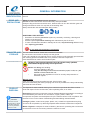
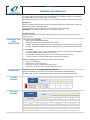
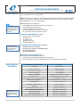
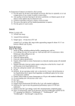
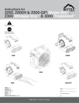
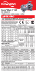
Certified Quality System
UNI EN ISO 9001 : 2008
www.comerindustries.com
312
SERVICE
MANUAL
PGRF
series
Release A10/14
First issue 10/14
Release A10/14
INDEX
GENERAL INFORMATION........................................................................................................................................................................................ 3
GEARBOX UNIT IDENTIFICATION.............................................................................................................................................................. 3
RISKS AND PRECAUTIONS......................................................................................................................................................................... 3
TRANSFER AND STORAGE........................................................................................................................................................................ 3
HANDLING.................................................................................................................................................................................................... 3
PRODUCT DISPOSAL.................................................................................................................................................................................. 3
GEARBOX UNIT............................................................................................................................................................................................ 4
INTENDED USE AND LIMITATIONS............................................................................................................................................................ 4
LUBRICANT.................................................................................................................................................................................................. 4
ORDINARY MAINTENANCE..................................................................................................................................................................................... 5
MAINTENANCE............................................................................................................................................................................................. 5
MAINTENANCE INTERVALS........................................................................................................................................................................ 5
OIL REPLACEMENT PROCEDURE......................................................................................................................................................................... 6
OIL DRAINING.............................................................................................................................................................................................. 6
OIL TOPPING OFF........................................................................................................................................................................................ 6
OIL FILLING.................................................................................................................................................................................................. 6
INSTALLATION AND START UP................................................................................................................................................................... 7
PRELIMINARY CHECKS AND INSTALLATION............................................................................................................................................ 7
START UP..................................................................................................................................................................................................... 7
MALFUNCTIONING AND FAILURE.............................................................................................................................................................. 7
FUNCTIONING INTERRUPTION............................................................................................................................................................................... 7
TROUBLESHOOTING............................................................................................................................................................................................... 8
TORQUE WRENCH SETTING.................................................................................................................................................................................. 9
This manual :
• provides all information about ordinary maintenance, installation and use for this unit,
• must be read and understood by the authorized people/operators before any kind of intervention,
• must be kept handy, in a safe place and must always be clear and legible for future reference whenever needed.
SYMBOLS USED
OBLIGATION
Operation to be observed
PROTECTIVE CLOTHING Protective clothing must always be worn by personnel
authorized to work with reduction gears.
PROHIBITION
Do not work with machines in movement
SAFETY GLASSES
Safety glasses must be worn by all autorized people to
work on the reduction gear
WARNING
Operation must be carried out with extreme care with
personal injury if proper procedures are not followed
SAFETY GLOVE
Safety glove must be worn by all autorized people to
work on the reduction gear
DANGER
Be careful of hanging loads
SAFETY SHOES
Safety shoes must be worn by all autorized people to
work on the reduction gear
PGRF
2/9
First issue 10/14
Release A10/14
GENERAL INFORMATION
GEARBOX UNIT
IDENTIFICATION
RISKS AND
PRECAUTIONS
All the data which characterize the gear unit are reported on the name plate attacched on
the unit.
Safety of authorized workers must be guarantee.
Provide all authorized worker with all necessary and specific IPG.
Example: Slip-proof shoes should be worn, because there is oil in the reduction gear and
during maintenance some of it may leak in the working area.
Always handle the units with adequate lifting means.
ADDITIONAL PRECAUTIONS
• Guarantee an effective prevention system by constantly monitoring cleaning and
integrity of the structures.
• Actuate a specific periodical cleaning and maintenance plan of the unit.
• In case of accidental overloads or damage to the unit, stop functioning unit and carry
out a repairing procedure.
Do not work with machines in movement.
TRANSFER AND
STORAGE
The unit is best stored in closed and covered environments.
Do not store the unit ouside or directly onto the ground.
If the unit is stored for long periods (over 3 month), these must be externally protected with
anti-oxidizing products and filled with oil to protect the internal components.
Care should also be used to avoid violent impact.
HANDLING
Handling, lifting and transportation must be carried out by qualified,
authorized and appropriately trained personnel.
Before and during unit handling:
•
check the stability of the unit;
•
verify that the lifting means and its accessories (ropes, hooks, etc.) are
suitable to lift and handle the unit;
•
follow strictly the regulations in force for security and prevention of
industrial injuries.
Manual loads:
If the unit or its parts must be handled manually, limit the load to 10Kg.
We recommend lifting the load by keeping it as close as possible to the body and bending
the knees and not the back.
PRODUCT
DISPOSAL
Environmental
protection:
Local rules must be
complied with in regard
to the laws existing in
the country where the
machine is used
PGRF
The disposal of waste material deriving from machine/components demolition must be
done with respect for the environment, without polluting land, air or water.
Dismantling: parts and components must be disassembled and separated in according to
the materials they are made of: iron, aluminium, copper, plastic, rubber, etc.
Components and parts must be disposed of by the relative centres in full compliance with
the laws in force on the matter of dismantling and demolishing industrial waste.
Packages (pallets, carton boxes, paper, plastic, etc.) to lead into regeneration/recycling
circuits as far as possible, by delivering separate waste classes to authorized compaines.
Waste oil/grease: to dispose of waste oil abide by the laws for protecting the environment
and the laws in force in the Country where the machine is used.
3/9
First issue 10/14
Release A10/14
GENERAL INFORMATION
GEARBOX UNIT
Most materials of these gearboxes are made of high quality steel and cast iron that have
to comply with the increasingly strict requirements on workability, resistance to distortion,
to fatigue failures and to wear, safety and durability.
All technical information are described in the documents referred to the specific unit code.
Brake unit:
the unit could be equipped with hydraulics negative brakes with oil-bath disks, expressly
designed for static or parking braking.
Correct braking values are described on the specific external drawing.
WARNING: It is strictly forbidden to use it as a dynamic brake.
Hydraulic motor:
to select the hydraulic motor take into consideration the maximum performance of the
reduction gear.
INTENDED USE
AND
LIMITATIONS
This gearbox unit must be:
• used only for industrial application;
• used with correct type and quantities of lubricants;
• handled, assembled, installed, used and maintained in compliance with this manual;
• handled, assembled, installed, used and maintained only by authorized workers/operator.
It is forbidden:
• to use the gearbox unit in a way that does not conform to the technical specifications
and the intended use described in this manual;
• to install and use this gearbox unit in environments with explosion risks;
• to use the gearbox unit with safety devices removed or disabled.
External drawing and documents annexed to the unit, report:
• technical informations;
• dimensions and characteristics;
• maximum number of input/output speed (rpm);
• maximum functioning values (torque, dimensions, etc...).
LUBRICANT
Gearboxes normally are supplied without lubricant.
Type and quantity of lubricant are indicated on the specific external drawing.
All fluids used must be compatible with all the components, elastomers and seals.
Oil type
Example
Viscosity
Oil
Type
Oil name
Example
Mineral
ISO VG 150
- 10°C
+ 30°C
ISO VG 220
+ 10°C
+ 45°C
ISO VG 320
+ 30°C
+ 60°C
Synthetic
PAO
- 20°C
+ 60°C
PG
- 20°C
+ 60°C
La viscosità aumenta al diminuire della temperatura e viceversa
Producer
SHELL
EXXON MOBIL
KLÜBER
AGIP
BP
CASTROL
CHEVRON
TOTAL
PGRF
Ambient temperature t°C (min / max)
Lubricants
Mineral
Omala S2G
Mobilgear XMP
Kluberoil GEM1
Blasia
Energol GR‐XP
Alpha SP
Ultra Gear
Carter EP
Synthetic
PAO
PG
Omala S4GX
Omala S4 WE
Mobil SHC Gear
Glygoyle
Klubersynth EG4
Klubersynth GH6
Blasia SX
Blasia S
Enersyn EPX Enersyn SG XP Aphasyn EP
Alphasyn PG
Tegra Synthetic Gear
HiPerSYN
Carter SH
Carter SY
Lubrificante per uso alimentare: contattare il servizio tecnico commerciale
Lubrificante biologico: contattare il servizio tecnico commerciale
4/9
First issue 10/14
Release A10/14
ORDINARY MAINTENANCE
Maintenance operations must be carried out by qualified, trained and authorised personnel
MAINTENANCE
To guarantee long life and excellent performance to the gear unit, maintenance operations must be done on a regular basis.
Before maintenance operations, authorized people must disconnect the unit power supply,
putting it “out of order”, taking all the necessary precautions to ensure it cannot be restarted accidentally or any of its moving parts.
When
maintenance operations
are finished, restore all
safety conditions of
functioning
During maintenance operations:
• it is forbidden to work with machines in movement,
• wear suitable protection (IPG),
• avoid accidental restart of the unit ,
• oil leaks should not be a source of danger,
• do not handle units that are still very hot.
ORDINARY MAINTENANCE includes:
• check of oil level and oil leaks,
• oil topping off,
• oil replacement,
• grease topping off,
• periodical inspection.
Note: Instruction for
extraordinary maintenance
are NOT described
in this manual
EXTRAORDINARY MAINTENANCE include:
• disassembly and reassembly;
• replacement of wearing or damaged parts;
• bearing replacement;
• oil seals replacement.
MALFUNCTION AND ANOMALIES
When malfunctions/anomalies are found:
• schedule an immediate/anticipated general overhaul;
• replace damaged or faulty components with new components if necessary.
MAINTENANCE
INTERVALS
Note: described
maintenance intervals
could be different with
different machine duty
cycle
PGRF
Inspection and Operations
Intervals
Oil leakage
before functioning
Brake functioning
before functioning
Oil and surface temperature
on functioning
Noise and vibrations
on functioning
FIRST OIL CHANGE
only after initial 100 service hours
Oil level check
every 500 service hours or monthly
Unit and plugs cleaning, oxidation, damage
every 500 service hours
ORDINARY MAINTENANCE
every 2000 service hours or at least once a year
Oil replacement
ordinary maintenance
Presence of water in the oil
after oil draining
Brake test
ordinary maintenance
Screws/plugs tightening torque
ordinary maintenance
EXTRAORDINARY MAINTENANCE
every 5000 service hours
Oil seals replacement
extraordinary maintenance
Bearings replacement
extraordinary maintenance
Brake disks and springs replacement
extraordinary maintenance
5/9
First issue 10/14
Release A10/14
OIL REPLACEMENT PROCEDURE
Maintenance operations must be carried out by qualified, trained and authorised personnel
OIL
DRAINING
Warning - BURNS
The oil could be very hot
and could cause burns
PROCEDURE:
• Position the unit with drain plug (
) placed down.
• Drain the oil: unscrew the drain plug (
) and, to ensure that all the oil has been
removed, also unscrew the level plugs.
After oil draining:
• replace all plugs and relatives washers or o-ring,
• refit all plugs and relatives washer on place in their seats.
In order to avoid sludge deposits, change the oil while the gear unit is still warm.
EXAMPLE OF
PLUGS
LAY OUT
FILLING
PLUG
OIL
LEVEL
Note:
correct plugs
configurations are
illustrated on the specific external drawings
OIL
LEVEL
PLUG
PLUG
DRAIN
PLUG
GROUND
OIL
TOPPING OFF
PROCEDURE:
OIL
FILLING
PROCEDURE:
•
•
•
•
•
•
DRAIN
PLUG
GROUND
Remove filling ( ) and level plug ( ). Topping up the unit adding oil lubricant from the upper hole (filling plug hole) until
correct OIL LEVEL reached: the oil flow out from the OIL LEVEL hole.
Remove filling ( ) and level plug ( ).
Fill the unit adding oil lubricant from the upper hole (filling plug hole) until correct OIL
LEVEL reached: the oil flow out from the OIL LEVEL plug hole.
When the oil filling procedure is finished, replace and tightening all plugs.
Correct oil quantity is indicated on the specific external drawing.
EXAMPLE OF
PLUGS
LAY OUT
FILLING
PLUG
FILLING
PLUG
OIL
LEVEL
Note:
correct plugs
configurations are
illustrated on the specific external drawings
PLUG
GROUND
Turn 90° counter-clockwise
Note:
for an effective oil
change, the unit should
be flushed through
with a liquid detergent
recommended by the
lubricant supplier
PGRF
OIL
LEVEL
PLUG
DRAIN
PLUG
GROUND
Warning:
if the quantity of oil
used during topping off is greater than 10 %
of the oil capacity then
check again for leaks
Warning:
Do not mix synthetic
lubricants with mineral
lubricants
6/9
First issue 10/14
Release A10/14
INSTALLATION and START UP
Installation and start-up must be carried out by qualified, trained and authorised personnel
PRELIMINARY
CHECKS AND
INSTALLATION
Before installation check and verify:
• motor type and connection;
• that unit components are not damaged and that the centering parts are not rusty;
• unit installation diagram;
• oil level/lubricant and type of lubricant;
• correct plug installation and efficiency;
• that the reduction gear screws and plugs have been tightened with correct values ;
• that there are no hazardous atmosphere in the work area.
To guarantee the correct unit installation:
• remove dirt and grease from the unit;
• lubricate spigots and coupling surfaces;
• centering and fixing the unit without forcing;
• dents or sparks must not be created/produced;
• friction between moving parts must be absent;
• install and fix the unit and all components correctly;
• take care not to deform the contact surfaces.
START UP
Before start up:
• remove unnecessary keys and tools;
• restore all unit safety system;
• all preliminary checks have been done;
• verify plugs and screws tightening;
• there are no oil leaks;
• make sure no radial or axial forces are applied;
• verify correct unit alignment with the structure;
• verify motor power connection;
• there are no obstacles that can influence the correct operation of the units;
Start-up and running in:
increase gradually torque and rotation values until max values allowed are achieved.
After starting up :
• friction between moving parts must be absent;
• excessive noise and vibration must be absent;
• carry out functional tests to verify:
• correct functioning of the unit;
• correct functioning of the safety system of the unit;
• that values functioning are respected.
Brake test:
carry out engage/disengage test to verify correct unlock pressure value and the brake torque value (correct values are described on the specific external drawings).
In case of malfunctioning:
1. interrupt and disable the functioning of the machine,
2. check and verify correct installation,
3. schedule an immediate/anticipated general overhaul of the gearbox unit.
MALFUNCTIONING In case of malfunctioning or failure:
1.disconnect the unit malfunctioning,
AND FAILURE
2.carry out a maintenance or repair plan,
3.replace the damaged or faulty components with new components.
FUNCTIONING
INTERRUPTION
PGRF
Disconnect unit malfuntioning and avoid accidental run of the unit.
Interrupt and disable the functioning of the machine/vehicle during maintenance operations, general overhaul or revision procedures (e.g. lifting the wheels off the ground,
turning off the work procedure...etc...) to avoid hurting operators and other people.
7/9
First issue 10/14
Release A10/14
TROUBLESHOOTING
Problems
1) Damaged or worn seals;
2) Breather plug clogged;
1) Contact Comer Industries;
2) Clean or substitute the plug
Excessive
overheating
1) There is no oil in the unit;
2) Incorrect level of lubricant;
3) Brake malfunctioning;
4) Excessive layer of dust;
5) Inadeqaute ventilation;
6) Internal problem.
1) Filling the unit with oil;
2) Restore correct level of lubricant
(oil/grease);
3) Verify brake functioning;
4) Clean the unit;
5-6) Contact Comer Industries;
Excessive noise 1
Internal problem
•Restore correct oil level.
•Restore correct grase q.ty.
•Contact Comer Industries.
Excessive noise 2
External problem
•Verify screws/connection.
•Verify unit installation.
1) Incorrect installation;
2) Internal problem;
1) Verify installation and screws
tightening;
2) Contact Comer Industries;
The unit fail to run
1) Incorrect motor installation;
2) Internal problem
1) Verify motor installation and
connection;
2) Contact Comer Industries;
Wrong rotation unit
direction
Uncorrect motor connection
Verify unit installation and connection;
The unit does not rotate
1) Incorrect motor installation;
2) Internal problem
1) Verify motor installation and
connection;
2) Contact Comer Industries;
1) Brake components damaged or
worn;
1) Replace brake components;
1) Incorrect dimensioning
•Verify unit scheme.
•Contact Comer Industries.
Brake malfunctioning
PGRF
Remedies
Oil leaks
Excessive vibration
In case of different problems from
this table, contact the
Technical-Commercial Service
Comer Industries
Possible cause
The unit cannot
assembled on the
structure machine
Maintenance data sheet
Maintenance data sheet
Date of maintenance work ................................ Date of maintenance work ................................ Operating hours ................................................ Operating hours ................................................ Comer Industries code ..................................... Comer Industries code ..................................... Serial number .................................................... Serial number .................................................... Work carried out:
Work carried out:
8/9
First issue 10/14
Release A10/14
TORQUE WRENCH SETTING (N x m)
Screw on steel or cast iron
PGRF
9/9