1
0
Manuale Installazione Uso e Manutenzione
Riduttori Epicicloidali
Installation, Operation and Service Manual
Planetary Gearboxes
Handbuch für installation, betrieb und
wartung
Planetengetriebe
ATEX included
7
INDEX
1. GENERAL INFORMATION ................................................................................................................................................ 42
1.1
TERMS AND SYMBOLS ............................................................................................................................................. 42
1.2
SUPPLY ......................................................................................................................................................................... 43
2. SAFETY INFORMATION .................................................................................................................................................... 44
2.1
GENERAL SAFETY WARNINGS ............................................................................................................................. 44
2.2
SAFETY WARNINGS FOR HANDLING WHEN UNPACKING AND TRANSPORTING ................................ 45
2.3
SAFETY WARNINGS FOR USE AND OPERATION ............................................................................................. 45
2.4
SAFETY WARNINGS FOR INSTALLATION AND ASSEMBLY......................................................................... 45
2.5
SAFETY WARNINGS REGARDING ENVIRONMENTAL IMPACT .................................................................. 45
2.6
SAFETY AND INFORMATION NOTICES .............................................................................................................. 45
2.7
CONSTRUCTOR LIABILITY .................................................................................................................................... 45
2.8
RESIDUAL RISKS ....................................................................................................................................................... 46
2.9
REASONABLY EXPECTED INCORRECT USES .................................................................................................. 46
3. TECHNICAL INFORMATION ............................................................................................................................................ 47
3.1
GENERAL DESCRIPTION OF THE MACHINE .................................................................................................... 47
3.2
CONDITIONS AND RESTRICTIONS OF USE ....................................................................................................... 47
3.3
TECHNICAL DATA .................................................................................................................................................... 48
3.4
STRUCTURAL FORMS .............................................................................................................................................. 49
3.5
DESIGN FORMS .......................................................................................................................................................... 50
4. TRANSPORT, HANDLING AND STORAGE .................................................................................................................... 51
4.1
HANDLING OF PACKAGING ................................................................................................................................... 51
4.2
HANDLING OF EQUIPMENT ................................................................................................................................... 51
4.3
STORAGE ..................................................................................................................................................................... 53
5. INSTALLATION AND ASSEMBLY ................................................................................................................................... 54
5.1
DIRECTION OF ROTATION ..................................................................................................................................... 54
5.2
SERIES RE/GB GEARBOX DESIGNS ...................................................................................................................... 56
5.2.1. Flanged design ........................................................................................................................................................... 56
5.2.2. Female grooved shaft design .................................................................................................................................... 58
5.2.3. Design with feet ......................................................................................................................................................... 59
5.2.4. Pendular design ......................................................................................................................................................... 59
5.3
CONNECTIONS ........................................................................................................................................................... 60
5.4
INPUT CONNECTIONS .............................................................................................................................................. 61
5.4.1. Connection to hydraulic motor ................................................................................................................................ 61
5.4.2. Connection to electric motor ................................................................................................................................... 62
5.4.3. Connection to fast shaft ............................................................................................................................................ 63
5.4.4. Connection to brake .................................................................................................................................................. 63
5.5
GEARBOX MOTOR INSTALLATION ..................................................................................................................... 64
5.6
FITTING ACCESSORIES ........................................................................................................................................... 65
5.7
SLEWING GEARBOX INSTALLATION: ................................................................................................................ 66
6. START-UP AND TESTING .................................................................................................................................................. 67
7. LUBRICATION ...................................................................................................................................................................... 69
7.1
TYPE OF LUBRICATION .......................................................................................................................................... 69
7.2
SELECTING AN OIL ................................................................................................................................................... 69
7.3
BRAKE LUBRICATION ............................................................................................................................................. 70
7.4
OIL FILLING AND LEVEL CHECKING ................................................................................................................. 70
7.4.1. Horizontal fitting: ..................................................................................................................................................... 70
7.4.2. Vertical fitting: .......................................................................................................................................................... 70
7.5
FILLING PROCEDURE .............................................................................................................................................. 71
7.5.1. Filling procedure with expansion chamber............................................................................................................. 71
7.6
AMOUNT OF OIL ........................................................................................................................................................ 71
8. SUPPORT AND SERVICING ............................................................................................................................................... 72
8.1
ROUTINE SERVICING ............................................................................................................................................... 73
8.2
SUPPLEMENTARY SERVICING.............................................................................................................................. 74
8.3
OIL REPLACEMENT .................................................................................................................................................. 74
8.3.1. Oil replacement procedure ....................................................................................................................................... 74
8.4
GREASE REPLACEMENT......................................................................................................................................... 75
9. BREAKDOWNS AND SOLUTIONS ................................................................................................................................... 76
10.
DISMANTLING AND DISPOSAL .................................................................................................................................. 77
40
ANNEX 1 – AMOUNTS OF OIL AND WEIGHTS .................................................................................................................. 118
ANNEX 2 – TIGHTENING TORQUES FOR LARGE PITCH SCREWS AND CAPS ........................................................ 122
ANNEX 3 – NEGATIVE HYDRAULIC MULTI DISK BRAKES .......................................................................................... 127
Revisions
The revision index of this manual can be found on the last page (p. 135).
The most up-to-date versions of Dinamic Oil S.p.A. catalogues and manuals are available at www.dinamicoil.com
41
1 GENERAL INFORMATION
The instructions contained in this manual are an integral part of the planetary gearboxes range.
All required information for purchasers and engineers is included on the dimensional drawings and data
sheets provided in the proposal. In the absence of such information, the data provided in the catalogue
should be considered correct.
In addition to adhering to rules of best practice in construction, this information should be carefully read and
stringently applied. If in any doubt, contact the DINAMIC OIL S.p.A. technical assistance service.
These installation instructions have been designed for the safety of all persons carrying out assembly, transport,
handling, installation, start-up and support on planetary gearboxes, however any other technical or specific
documentation from the order must also be followed.
There may be attachments to this manual.
The manual is relevant to the following units:
•
Planetary gearboxes
To comply with their "intended use", they must be operated as described in this manual, and in accordance with the
other technical documents (data sheets, catalogues, etc.).
The manufacturer has designed these units for industrial uses. Any use, application and/or installation beyond those
described in this manual and other technical documents (data sheets, catalogues etc.) must be agreed/approved by
the DINAMIC OIL S.p.A. technical assistance service.
For the purposes of Directive 2006/42/EC on machinery, the gearbox is considered partly completed machinery which
will be fitted onto other machines and/or installations. The gearbox must not be incorporated into them and used until
all safety issues have been resolved, and it is not permitted to start up the final product (for its intended use) until it
has been verified as compliant with Directive 2006/42/EC on machinery.
The customer must accept responsibility for compliance with the Directive 2006/42/EC on machinery and any other
community directive relating to safety of machinery.
Planetary gearboxes can pose hazards to persons, animals and material goods. For this reason, all handling,
transport, fitting, installation, start-up and support operations must only be carried out by personnel who are trained,
qualified and authorised to carry out the task, and who are aware of the potential hazards.
Personnel must have the required qualifications for the task to be carried out, and have attested experience in
handling, transporting, fitting, installing, starting up and supporting planetary gearboxes
(see point 2).
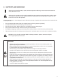
1.1
TERMS AND SYMBOLS
Warning
Precautionary measures to be followed to ensure the safety of the operator and
persons present in the working area, animals and objects.
Specialist, authorised personnel
Operations which must only be performed by specialist, authorised personnel.
Information
Important information or procedures.
Customer = Manufacturer of final machinery
Manufacturer of final machinery = Person fitting the "partly completed machinery" (gearbox) onto the final
machinery
Manufacturer/Constructor = DINAMIC OIL S.p.A.
42
Instructions given next to the Ex symbol only apply to equipment compliant with the 94/9/EC
"ATEX" directive.
Activities referenced by this symbol must only be performed by professionally qualified and
authorised personnel with specific training on safety issues relating to areas with potentially
explosive atmospheres.
Failure to adhere to these instructions can pose serious risks to the safety of persons, animals and
objects.
Instructions given next to the Ex symbol should be interpreted as additional instructions to those
provided for installation, use and servicing of standard gearboxes, and not as a replacement.
1.2
SUPPLY
Upon receipt of the gearbox, check that it has not been damaged and that the item supplied
matches the one ordered. If any of these conditions is not fulfilled, contact the DINAMIC OIL
S.p.A. sales technical assistance service immediately.
DINAMIC OIL S.p.A. gearboxes are delivered in cases, pallets, carton pallets or simple cardboard boxes, which
are carefully organised to prevent movement.
The packaging material should be disposed of according to the national and international environmental standards
in force.
Take the utmost care when unpacking.
The gearboxes are supplied as follows:
• Arranged for installation in the assembly position stated when the order was placed.
• Without lubrication oil, unless otherwise provided for by contractual arrangement.
• Painted externally with a red, water-based, anti-oxidising undercoat, unless otherwise provided for by contract.
This protective coating is suitable for normal industrial environments, even outdoors, and allows further finishing
coats of synthetic paint to be applied.
• The external machined parts of the gearbox, such as the outside of the shafts, the resting surfaces and centring
units, as well as the internal kinematic mechanisms, require protection with anti-oxidising oil.
43
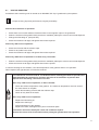
2 SAFETY INFORMATION
Follow the simple instructions given in the relevant parts of the manual to reduce or eliminate risk
situations.
2.1
GENERAL SAFETY WARNINGS
•
These safety warnings apply to all types of gearbox, gears and other Dinamic Oil S.p.A. products
•
Safety warnings contained in the other chapters of this manual must also be adhered to
•
The safety warnings must be adhered to at every stage of the product life cycles described in this manual
(transport, handling, packaging, storage, installation/fitting, start-up/operation, servicing,
dismantling/disposal)
•
Failure to adhere to the safety warnings can pose serious health risks and harm to objects and animals
•
If in any doubt about the safety warnings, contact the Dinamic Oil technical assistance service
•
The personnel that this manual is addressed to must have attested experience and be authorised to carry
out the operations
•
While performing the various operations, personnel must also adhere to national and international
standards on safety and safe working practices
•
Installing and operating damaged units can pose serious safety risks
•
Serious harm can be caused to persons, animals or objects as a result of:
¾
¾
¾
Improper use
Incorrect installation or use
Unauthorised removal of protection systems
The following risks arise during and after gearbox operation:
•
¾ Overheated parts
¾ Moving parts
¾ Parts under pressure
Before carrying out any task, personnel responsible for installation, use and servicing in areas with
potentially explosive atmospheres must carry out all necessary environmental safety measures
(e.g. degassing or removal of residual dust, etc.).
44
2.2
SAFETY WARNINGS FOR HANDLING WHEN UNPACKING AND TRANSPORTING
See point 4, "Transport, handling and storage".
2.3
SAFETY WARNINGS FOR USE AND OPERATION
Adhere to the information in the data sheet.
2.4
SAFETY WARNINGS FOR INSTALLATION AND ASSEMBLY
Adhere to the information in the data sheet.
2.5
SAFETY WARNINGS REGARDING ENVIRONMENTAL IMPACT
Units must be disposed of according to the environmental standards in force.
2.6
SAFETY AND INFORMATION NOTICES
Manufacturers carrying the CE mark are responsible for applying safety and information notices.
2.7
CONSTRUCTOR LIABILITY
The constructor will not be held liable in the event of:
•
Gearbox being used contrary to national laws on safety and safe working practices
•
Incorrect installation, inadequate or incorrect observance of the instructions given in this manual
•
Electrical or hydraulic power supply failure (for motor gears)
•
Alteration or tampering
•
Operations performed by untrained, unqualified or unauthorised personnel
•
Use, applications or installations beyond the instructions given the data sheets or this manual that have
not been approved by DINAMIC OIL S.p.A.
The safety of the gearbox also relies upon strict observance of the instructions given in this manual, and in
particular:
•
The gearbox must only be operated within its limitations of use (see data sheets, catalogues etc.)
•
Diligent routine servicing must always be carried out
•
Operators assigned to inspection and servicing must be sufficiently trained
•
Only original spare parts must be used
•
The configurations shown on the dimensional drawings and their instructions in the catalogue are the only
ones permitted
•
Do not attempt to use the gearbox in any other way than indicated by the provided instructions
•
The instructions given in this manual are supplementary to, and do not replace, obligations in legislation
on safety standards in force
45
2.8
RESIDUAL RISKS
Residual risks are potential hazards which cannot be eliminated or can only be partially eliminated, and which can
harm the operator if incorrect methods or working practices are used.
Note
Directive
2006/42/EC
Annex I
Description
19
1.3.4
Risks posed by surfaces, edges or angles
22
1.3.7
Risks related to moving parts
23
1.3.8
Choice of protection against risks arising from
moving parts
25
1.4.1
General requirements for guards and
protective devices
26
1.4.2.1
Fixed guards
28
1.4.2.3
Adjustable guards restricting access
29
1.4.3
Special requirements for protective devices
2.9
Remarks
Correct and non-hazardous
positioning is the responsibility of
the customer
Protection of the operator from
potential risks related to moving
parts is the responsibility of the
customer
Protection of the operator from
potential risks related to moving
parts is the responsibility of the
customer
The choice of requirements for
guards and protective devices is
the responsibility of the customer
Fitting any fixed guards is the
responsibility of the customer
Fitting any adjustable guards
restricting access is the
responsibility of the customer
The choice of special requirements
for protective devices is the
responsibility of the customer
REASONABLY EXPECTED INCORRECT USES
Incorrect use of the partly completed machinery is defined as a use different from that described in the instructions of
this manual and the data sheets, but which is reasonably expected human behaviour:
•
Negligence on the part of the operator to follow the instructions in this manual
•
Instinctive reactions of the operator
•
Lack of concentration or carelessness during installation or servicing
•
Behaviour resulting from the pressure to keep the machine running under any circumstance
46
3 TECHNICAL INFORMATION
3.1
GENERAL DESCRIPTION OF THE MACHINE
DINAMIC OIL S.p.A. gearboxes have been designed and built to be incorporated into and powered by an electric or
hydraulic motor, in finished devices or systems for use in industrial sectors such as construction, chemical,
mechanical, agri-foodstuff, transport, naval, etc., once the constructor has resolved all problems relating to the safety
of final regulations in accordance with Directive 2006/42/EC on machinery and other community directives
(e.g. ATEX).
For certain applications and to satisfy specific requirements, the gearbox may be supplied in various structural forms
and configurations, including a range of accessories and optional modifications. For all the technical and information
and descriptions about these, see the relevant sales catalogue.
It is the user's responsibility to use the gearbox in a correct manner, adhering to the warnings given in this manual.
Gearboxes approved for use in a potentially explosive atmosphere must be labelled with the
appropriate identification plate, and are protected and manufactured to comply with the Essential
Safety Requirements (ESR) in Annex II of the 94/9/EC "ATEX" directive. They comply with the
following:
3.2
•
Equipment group: II.
•
Category: Gas 2G – Dust 2D.
•
Zone: Gas 1 – Dust 21.
•
Maximum surface temperature: temperature class T4 for 2G and 130 °C for 2D.
CONDITIONS AND RESTRICTIONS OF USE
The gearbox may only be installed in the position indicated on the identification plate.
Any change to its installation position must be authorised by DINAMIC OIL S.p.A.
The recommended ambient temperature for use of standard gearboxes is: min. -15 °C; max. +40 °C
Using the gearbox in aggressive environments, in water or other liquids is not permitted unless agreed during the
planning stage.
Unless duly marked (ATEX plate), it is not permitted to use the gearbox in potentially explosive atmospheres or where
explosion-proof equipment is required.
If it does not have a plate, the gearbox is not permitted to be used on machinery operated in
potentially explosive atmospheres. If it is, liability for improper use or any harm to persons, objects
or animals rests with the customer.
Values for maximum surface temperatures relate to measurements in standard environmental
conditions and a standard installation.
Variations to these conditions, however small, including narrowed openings, external heat sources,
areas exposed to solar radiation etc., can have considerable effects on the build-up of heat.
Any modification to the structural form or installation position can pose potentially serious hazards
to the safety of persons, animals or objects. If these modifications are not approved and authorised
by Dinamic Oil S.p.A. the ATEX certification is rendered void and all liability rests with the
customer.
47
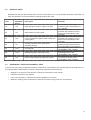
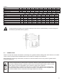
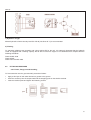
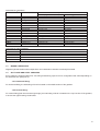
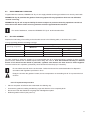
3.3
TECHNICAL DATA
The gearboxes are equipped with identification plates containing the unit's main technical and manufacturing
information. To interpret the product description (A), refer to the sales catalogue.
A) Product description/customer code*
B) Serial number (week, year, identifying number)
C) Product code
*The product description may be replaced by a code supplied by the customer.
Gearbox plate with ATEX option:
D) Number/registration body
E) Permitted assembly position
F) Reduction ratio
G) Maximum applicable power in kW with mechanical yield = 0.97 for each reduction stage, input
speed = 1500 rpm, ambient temperature = 20 °C, altitude = 0/500 m
H) Maximum input revolutions allowed for the connected electric motor in revs/minute
I)
Maximum transmissible applicable output torque in Nm
L) Mark of conformity according to Directive 94/9/EC
Ensure the identification plate is kept clean and clearly visible. If even one item of information
on it is no longer legible, request a copy from the manufacturer and replace it.
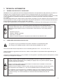
48
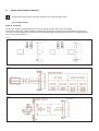
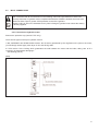
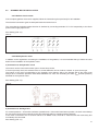
STRUCTURAL FORMS
37 - Pinion "P"
38 - Flange "FL"
39 - Grooved bush "BS"
40 - Hexagonal bushing "ES"
41 - Grooved bar "BF"
42 - Shrink disk "GA"
43 - End plate "EP"
44 - Expansion chamber "VE"
-,,*%%"$&*%
24 - Output support "N"
25 - Output support "P"
26 - Output support "T"
27 - Output support "TR"
28 - Output support "TL"
29 - Output support "H"
30 - Output support "F"
31 - Output support "NQ"
32 - Cylindrical output shaft
33 - Grooved output shaft
34 - Female grooved output shaft
35 - Hexagonal output shaft
36 - Female cylindrical output shaft
%)(("$#% -'+ ")#()# %/-0#%
18 - Direct mount bevel gear
19 - Single stage reduction
20 - Double stage reduction
21 - Three stage reduction
22 - Four stage reduction
23 - Five stage reduction
$*+),#&"' %#-.*%
9 - Motor connection adapter
10 - Fast shaft
11 - Direct electric motor adapter
12 - Direct orbital motor adapter
13 - Negative brake "F1../F2.."
14 - Negative brake "F5../F6../F8../F9"
15 - Standard flange
16 - "MZ" flange adapter
17 - "MD" flange adapter
&'()#%
1 - Electric motor
2 - Orbital motor
3 - Axial piston motor
4 - Radial piston motor
5 - Orbital motor "MLR"
!"#"$%
3.4
49
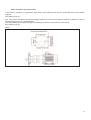
3.5
DESIGN FORMS
50
4 TRANSPORT, HANDLING AND STORAGE
Handling-trained personnel trained must ensure the required safety conditions are enforced for
themselves and for persons in the vicinity.
The cases only have load-bearing structure on the bottom, with the other sides for coverage only. Those
structures must therefore not be loaded.
4.1
HANDLING OF PACKAGING
Before handling the packaging, prepare an appropriate, marked out area with paving and a flat surface for unloading
and placing the packages on the ground.
When moving the package, use appropriate methods (e.g. forklift trucks, cranes or transpallets) for the type of
packaging, all in perfect working order, taking into consideration the packaging's size, weight and centre of gravity.
Keep the packages level to prevent them from tipping over during handling.
Use accessories that comply with the directive on machinery, and which are suitable for the weight to be
lifted.
The weight, gripping points and centre of gravity of the package to be handled are shown on
the package.
4.2
HANDLING OF EQUIPMENT
Before taking the gearbox out of its packaging, prepare the relevant lifting accessories (e.g. chains, bands, grills,
eyebolts etc.), or handle it using a pallet as a resting platform.
Take the utmost care when unpacking.
Use accessories that comply with the directive on machinery, and which are suitable for the weight to be
lifted.
51
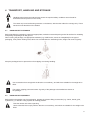
Lift the gearbox, taking care not to unbalance the load while moving.
Refrain from making abrupt movements and perform an initial slow manoeuvre to ensure that the load is
balanced.
Move and lay down the gearbox in the area prepared for unloading.
Examples are given below of the lifting points for the main DINAMIC OIL S.p.A. gearbox designs.
The weight of the equipment to be lifted can be found in Annex 1.
52
4.3
STORAGE
For correct storage of the units, the following steps must be taken:
• For storage for over 2 months, protect the coupling surfaces, such as the flanges, shafts and joints, with a very thin
layer of grease and/or protective anti-corrosion fluids.
• Store in a dry place with temperatures of between -5 °C and +30 °C.
• Always place wooden planks or a platform made of other materials between the unit and the floor, to prevent direct
contact.
• Do not stack the packages.
• Check the internal gears regularly by rotating the input shaft manually.
If the unit is fitted with negative lamellar brakes, release the brake with a hydraulic pump or suchlike.
• Before starting up the unit, we recommend you replace the washers of the static and rotary seals.
• For storage for over 6 months, fill the gearbox with the same type of oil as the oil that is planned to be used when
operational, placing the vent cap in the upper part of the gearbox.
Before starting up, fill the gearbox with the right amount of oil.
The static and rotary seals will begin to deteriorate after 6 months.
SAFETY PRECAUTIONS WHEN RESTORING THE GEARBOX AFTER STORAGE
All surfaces contaminated with lubricants, protection, solvents, dust or other potentially flammable
material must be carefully cleaned (commercial solvents).
This operation must be performed away from the area with the explosion hazard.
The solvent must not come into contact with the seal rings, avoiding damage to the equipment and
compromising its functionality.
Grease used for the bearings must strictly be synthetic in nature.
When filling with lubricating oil, check the amount of oil required for each gearbox size (Annex 1 of
this manual).
Place the gearbox in the assembly position indicated on the plate and check the right amount of oil
using the level caps. Once filled, wait 15-30 minutes for the oil to stabilise and top up if necessary.
When testing, check that the oil level in the gearbox is correct and top up if necessary.
When topping up, ensure the gearbox is taken out of service and take care with hot surfaces to
avoid serious harm to persons, animals or objects.
Filling and topping up must be performed by expert and authorised personnel, away from the area
at risk of explosion.
For the initial oil filling and any top ups, only the recommended oils should be used.
53
5 INSTALLATION AND ASSEMBLY
Gearboxes must be installed carefully and professionally, by suitably suitably trained and
technically skilled authorised personnel.
All the installation operations must be performed to ensure maximum safety levels are
guaranteed for both workers and third parties and that the gearbox operates correctly and
safely.
Before installing the gearbox, check that it is in the correct assembly position.
• Tampering with the gearbox and any of the accessories fitted during production is strictly prohibited
• When any lifting and handling manoeuvres are carried out, care must be taken to ensure the end of the shaft does
not hit anything. The relative hoisting straps and/or eyebolts must be used, suitably arranged, and with hoisting
means whose capacity is sufficient for the job
• Welding operations on gearboxes are strictly prohibited without suitable protection
• Any installation work or servicing must be carried out with the gearbox stationary, therefore it is recommended that
you ensure the gearbox cannot be switched on accidentally
• In the event of connections involving the use of rotary parts such as shafts, joint or pulleys with belts, suitable
accident prevention gear must be provided
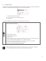
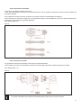
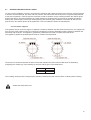
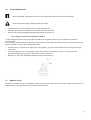
5.1
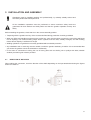
DIRECTION OF ROTATION
When making the connection, check the direction of the shafts depending on the input attached and using the figures
below for reference.
54
Installing gearboxes compliant with Directive 94/9/EC
•
Category 2D gearboxes must be installed according to EN 1127-1 and EN 50281-1-2
standards, and the installer must therefore have complete mastery of these.
•
The installer must know the ATEX classification of the installation zone, as well as the risks of
a potentially explosive atmosphere in the environment, with particular
emphasis on explosion and fire hazards, so that the relevant protection measures are taken.
•
All servicing, fitting and dismantling must be performed away from the area at risk of
explosion by qualified and authorised personnel.
•
Check that accessory parts (cables, joints, cable glands, heat exchangers etc.) are also
compliant with the essential safety requirements of the ATEX directive. They must be handled
with extreme care so they are not altered in any way.
•
Remove the screws from the threaded seat if they are required to fasten the gearbox. Do not
damage the coupling surfaces.
•
When installing gearboxes equipped with a reaction arm, prevent friction from being produced
between the moving metal parts when operational. If required, install non-metal anti-friction
parts compliant with 94/9/EC.
•
Do not attach any object to the unit with electrical resistance greater than 10 .
•
Take relevant measures to prevent hazardous dust/liquid from accumulating near the seals of
the protruding shafts and to protect the machinery.
•
If the gearbox motor is installed vertically downwards, the electric motor must be equipped with
a protective cover.
•
The axes between the output shaft and any pulleys or other transmission units must be
completely parallel.
•
The gearbox must only be installed in the structural form and assembly position specified in
the order.
•
If the gearbox was originally supplied without lubricant it must be installed as such, and only
filled with lubricant afterwards.
•
Secure the gearbox to a flat, vibration-damping surface which is sufficiently resistant to torsion.
•
Take care not to deform the contact surfaces, feet and/or assembly flanges by over-tightening
the screws.
•
When fastening gearboxes, screws of at least grade 8.8 quality must be used.
•
Ensure that no loads are placed on the gearbox greater than those given in the data sheets.
•
The vent caps and level check caps for the oil must be freely accessible and readily
serviceable.
•
Arrange for the gearbox to be cleaned once the installation phase is complete.
•
Arrange for the gearbox to be earthed to avoid a build-up of static charge.
55
5.2
SERIES RE/GB GEARBOX DESIGNS
General information unless otherwise indicated on the relevant data sheets.
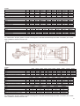
5.2.1.Flanged design
SIZES UP TO RE2000:
Prepare the coupling counterflanges on the unit or system on which they are to be installed.
The surfaces where the gearboxes will be coupled with the flange must be flat and worked with a machine tool.
Connect the output shaft to the mechanism to be controlled following the instructions given in the drawings below
(FIG. 1), (FIG. 2) and (FIG. 3).
(FIG. 1)
(FIG. 2)
(FIG. 3)
56
Table 1
Sizes
Screw
Quantity
Class
Tightening torque
Maximum torque tolerated by screws
Sizes
Screw
Quantity
Class
Tightening torque
Maximum torque tolerated by screws
Sizes
Screw
Quantity
Class
Tightening torque
Maximum torque tolerated by screws
No.
Nm
Nm
No.
Nm
Nm
No.
Nm
Nm
110N
M10
8
8.8
44
2,400
110T
M10
10
8.8
44
3,528
110TR
M10
10
8.8
44
5,153
110T1
M12
10
8.8
77
3,528
110TR1
M12
10
8.8
77
5,153
210N
M10
8
8.8
44
2,400
210T
M10
10
8.8
44
3,528
210TR
M10
10
8.8
44
5,153
210T1
M12
10
8.8
77
3,528
210TR1
M12
10
8.8
77
5,153
240T
M12
10
8.8
77
5,153
240TR
M10
10
8.8
44
5,126
310N
M12
10
8.8
77
5,153
310T
M12
10
8.8
77
6,474
310TL
M12
10
8.8
77
6,474
510/610N
510/610T
M12
10
8.8
77
6,474
510/610TL
M12
10
8.8
77
6,474
810N
M14
12
8.8
122
10,860
810T
M14
12
8.8
122
10,860
1020T
M16
10
8.8
191
14,493
1520T
M16
10
8.8
191
14,493
M12
10
8.8
77
5,153
2000T
M16
10
8.8
191
14,493
For transmission torques greater or equal to those given in the table and with frequent motion inversions, use screws
with a resistance class of at least 10.9.
(FIG. 4)
Table 2
Sizes
Screw
Quantity
Class
Tightening torque
Maximum torque tolerated by screws
Sizes
Screw
Quantity
Class
Tightening torque
Maximum torque tolerated by screws
Sizes
Screw
Quantity
Class
Tightening torque
Maximum torque tolerated by screws
No.
Nm
Nm
No.
Nm
Nm
No.
Nm
Nm
1520H
M16
16
12.9
323
31,240
21000H
M27
36
8.8
944
342,309
110000H
M42
40
8.8
3,582
2,038,800
2000H 2520H 3000H 3510H 4800H 6000H
8000H 12010H 16000H
M16
M16
M16
M16
M16
M18
M18
M24
M24
16
21
21
24
24
36
36
36
36
12.9
12.9
12.9
12.9
12.9
12.9
12.9
8.8
8.8
323
323
323
323
323
444
444
645
645
31,240 46,014 46,014 63,276 63,276 108,782 108,782 148,572 148,572
26000H
M27
36
8.8
944
342,309
31000H
M30
36
8.8
1,282
512,633
130000H
M42
40
8.8
3,582
2,038,800
40000H
M30
36
8.8
1,282
512,633
150000H
M42
40
8.8
3,582
2,038,800
45000H
M30
36
8.8
1,282
512,633
53000H
M36
36
8.8
2,240
940,487
205000H
M42
48
8.8
3,582
2,038,800
61000H
M36
36
8.8
2,240
940,487
85000H
M36
36
8.8
2,240
940,487
235000H
M42
48
8.8
3,582
2,038,800
For transmission torques greater or equal to those given in the table and with frequent motion inversions, use screws
with a resistance class of at least 10.9.
57
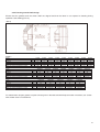
5.2.2.Female grooved shaft design
Ensure that the gearbox and the driven shaft are aligned and that the latter is not exposed to bending during
operation. See drawing (FIG. 5).
(FIG. 5)
Table 3
Sizes
Screw
Quantity
Class
Tightening torque
Maximum torque tolerated by screws
Sizes
Screw
Quantity
Class
Tightening torque
Maximum torque tolerated by screws
Sizes
Screw
Quantity
Class
Tightening torque
Maximum torque tolerated by screws
No.
Nm
Nm
No.
Nm
Nm
No.
Nm
Nm
110FS
M10
8
12.9
75
4,050
210FS
M10
8
12.9
75
4,050
26000FS
M27
36
8.8
944
342,309
110000FS
M42
40
8.8
3,580
2,038,800
240FS
M10
8
12.9
75
4,050
31000FS
M30
36
8.8
1,282
512,633
310FS
M10
12
12.9
75
8,175
40000FS
M30
36
8.8
1,282
512,633
130000FS
M42
40
8.8
3,580
2,038,800
510FS
M10
12
12.9
75
8,175
45000FS
M30
36
8.8
1,282
512,633
150000FS
M42
40
8.8
3,580
2,038,800
810FS
M12
12
12.9
130
14,180
53000FS
M36
36
8.8
2,240
940,487
205000FS
M42
48
8.8
3,580
2,038,800
1020FS
M12
16
12.9
130
18,907
1520FS
M16
16
12.9
323
31,240
61000FS
M36
36
8.8
2,240
940,487
2000FS
M16
16
12.9
323
31,240
85000FS
M36
36
8.8
2,240
940,487
235000FS
M42
48
8.8
3,580
2,038,800
For transmission torques greater or equal to those given in the table and with frequent motion inversions, use screws
with at least class 10.9 resistance.
58
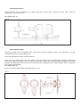
5.2.3.Design with feet
These gearboxes must be fastened to a suitably sturdy base worked with a machine tool and with a maximum
planarity error of 0.3 mm/0.8 mm.
See drawing (FIG. 6).
(FIG. 6)
5.2.4.Pendular design
Fasten the reaction arm to the gearbox with screws with a minimum resistance class of 8.8 tightened to a torque
corresponding to 70 % of their yielding load.
Clean and degrease the shafts' coupling surfaces.
Apply a thin layer of lubrication to the outer surface of the joint, then fit it on the gearbox shaft. Tighten an initial group
of 3 screws. Couple the gearbox with the shaft to be controlled. Tighten the screws gradually, proceeding in a circular
direction and tightening several times to ensure all the screws are tightened to the torque stated in table 4, depending
on the type of joint/gearbox.
See drawing (FIG. 7).
Note: Do not tighten diametrically opposed screws in a row.
(FIG. 7)
59
Table 4
Sizes
Screw
Quantity
Class
Tightening torque
Sizes
Screw
Quantity
Class
Tightening torque
No.
Nm
No.
Nm
Sizes
Quantity
Class
Tightening torque
No.
Nm
110
M6
10
10.9
13
210
M6
10
10.9
13
240
M8
12
10.9
31
310
M8
12
10.9
31
510/610
M8
12
10.9
31
810
M8
12
10.9
31
1020
M16
10
10.9
270
1520
M16
16
10.9
270
2000
M16
16
10.9
270
2520
M16
21
10.9
270
3000
M16
21
10.9
270
3510
M16
24
10.9
270
4800
M16
24
10.9
270
6000
M16
36
10.9
270
8000
M16
36
10.9
270
12010
M20
36
10.9
525
16000
M20
36
10.9
525
21000
M20
36
10.9
525
26000
M20
36
10.9
525
31000
M20
36
10.9
525
40000
M24
36
10.9
907
45000
M24
36
10.9
907
53000
M24
36
10.9
907
61000
M24
36
10.9
907
85000
M24
36
10.9
907
To prevent abnormal loads on the gearbox bearings if the motor is coupled directly, it must be integral to
and therefore pendulate with the gearbox.
5.3
CONNECTIONS
Fasten the input and output mechanisms connecting to the gearbox without striking them with hammers or suchlike.
Use the service screws and the threaded holes on the shafts for inserting the mechanisms.
Before fitting the connecting mechanisms, remember to clean the shafts to remove any traces of grease and/or
protective treatments.
To meet the requirements of areas at risk of explosion between coupled areas with friction hazards
and therefore flashing hazards, material must be used to avoid this (rubber pastes, rubber or teflon
inserts, sealant). It is the responsibility of the customer to apply such measures.
Use a suitable quantity of sealant as Loctite 510 or suchlike for the gearbox input couplings with
the motor and the output drivers to the customer's machine. This sealant must be compatible with
the ATEX installation area to avoid dust and foreign bodies from entering.
60
5.4
INPUT CONNECTIONS
After verification that all the instructions in the following manual and specified above have been
correctly observed, if a gearbox motor compliant with Directive 94/9/EC is desired, the motor to be
fitted must have equal or greater ATEX protection to that of the gearbox.
Dinamic OilS.p.A. will not be held liable for any risks in fitting the gearbox-motor unless the entirety
is directly supplied.
5.4.1.Connection to hydraulic motor
Remove the protective cap (version F1/F2 only).
There are two types of set-up for hydraulic motors:
1 MO, F5/F6/F8/F9 and ST/MU+PAM versions: the oil seal is guaranteed by the ring fitted on the joint on the motor;
you will simply need to apply a thin layer of oil to the driving shaft.
2 F1/F2 version: fit the O-Ring which guarantees the seal between the motor and the brake, taking care to fit it
correctly in its seat without damaging it.
See drawing (FIG. 8).
(FIG.8)
61
5.4.2.Connection to electric motor
If the motor in question is a particularly high power motor (ME-225 and above), use B3-B5 motors with suitable
supports.
See drawing (FIG. 9).
N.B.: The motors must always be perfectly aligned whether the motor and the gearbox shaft are coupled with a joint or
(and especially) if they are coupled directly.
Incorrect positioning can cause damage to the bearings on both the motor and the motor set-up.
See drawing (FIG. 9).
(FIG.9)
62
5.4.3.Connection to fast shaft
Clean all the mechanisms before connection.
In the event that pulleys for belt drives or toothed pinions for chain gearing are fitted, the shafts must be parallel and
the pulleys aligned.
Do not tighten the belts more than necessary as excessive tension could damage the bearings.
If the connection is made with a rigid joint, a compensation system must be added to recover any phase displacement
between the fast shaft and the gearbox fastening.
See drawing (FIG. 10)
(FIG. 10)
5.4.4. Connection to brake
For gearboxes arranged for hydraulic motors and complete with brakes,
when installing, connect to the hydraulic control hole on the brake body with a suitable hydraulic circuit pipe.
See drawing (FIG. 11).
(FIG. 11)
For further information about Dinamic Oil brakes please refer to annex 3 of this manual
63
5.5
GEARBOX MOTOR INSTALLATION
5.5.1.With an electric motor.
If the complete gearbox motor set is supplied, follow the instructions given previously for its installation.
The electrical connection types are stamped inside the terminal cover.
The conventional clockwise rotation direction is obtained by connecting terminals U1-V1-W1 respectively to the direct
power mains supply triplet R-S-T.
See drawing (FIG. 12)
(FIG. 12)
5.5.2.With hydraulic motor
In addition to the regulations concerning the installation of the gearbox, it is recommended that you follow the rules
below for the installation of the hydraulic motor.
a) Connection to the hydraulic circuit
The motors can be connected in either open or closed loop circuits.
If it is an open loop circuit, the solenoid valve or control distributor can be of either a closed- or open-centre type.
The branch of the circuit corresponding to the hydraulic motor delivery side or the flanged side of the motor must
always have a maximum pressure valve fitted calibrated to a value not exceeding the value pint (internal pressure)
admitted for the hydraulic motor.
See drawing (FIG. 13).
(FIG. 13)
b) Connection to drainage hole
For counter-pressure > 15 bar with continuous operation and > 30 bar with intermittent operation, the drain must always
be connected unless the the hydraulic motor has reinforced seals for operating without drainage.
If the motor connected to the F1 and F2 brakes is an OMSU motor, the drain is machined into the brake body and
must always be connected.
See drawing (FIG. 14)
64
(FIG. 14)
c) Hydraulic oil type
Mineral hydraulic oil with viscosity level ISO VG 46 (46 cSt at 40 °C) is recommended.
d) Filtering
To guarantee reliable motor operation and a long working life for the unit, it is extremely important that the hydraulic
circuit is equipped with a filtering capacity that is able to ensure a degree of oil cleanliness that complies with the
following standards:
Grade 9 NAS 1638
Grade 6 SAE
Grade 18/15 SO DIS 4406
5.6
FITTING ACCESSORIES
5.6.1.Pinion, flange, smooth bushing
To fit accessories onto the grooved shaft, proceed as follows:
•
Apply a thin layer of anti-seize lubricant or grease to the groove.
•
Push the accessory into the output shaft until the stopping point on the shaft is reached.
•
Insert the retainer plate and tighten the fastening screws.
65
5.7
SLEWING GEARBOX INSTALLATION:
To carry out the installation correctly, check that the centerings and support surfaces on the reducer, and the structure
to which it must be fastened, are clean and free of dents. Also make sure that the structure is rigid and perpendicular
to the axis of operation. These checks are important in order to obtain a correct meshing between the reducer pinion
and the fifth wheel. The latter generally has a mark (with three coloured teeth) on the point of greatest (for slewing
bearing with external gear) or least (for slewing bearing with external gear) ovalisation of the pitch Ø, which is the
point in which the reducer pinion will be positioned. If it is not indicated, contact the manufacturer.
5.7.1.Eccentric support:
If the gearbox has an eccentric support, to adjust the clearance between the fifth wheel and the pinion, the support will
have a notch at the minimum point of eccentricity indicating the minimum obtainable meshing clearance between the
fifth wheel and the pinion. This applies to gearboxes positioned both inside or outside of the fifth wheel.
This applies to gearboxes positioned both inside or outside of the fifth wheel.
The amount of clearance between the sides of the teeth between the pinion and the fifth wheel is obtained by
multiplying the module (m) of the toothing by two fixed values given in the table below.
m5
m6÷m10
>m10
0.1-0.2
0.3-04
0.4-0.8
The resulting values provide a range that the clearance between the teeth must lie within to allow perfect meshing.
Grease the teeth before use
66
6 START-UP AND TESTING
Improper start-up can damage the gearbox.
At the factory the gearbox's seals are checked for leaks and a vacuum test is performed.
Check the following before start-up:
•
That the machinery incorporating the gearbox is compliant with Directive 2006/42/EC on machinery and any other
applicable safety standards in force
•
That all rotating parts are sufficiently protected in compliance with Directive 2006/42/EC on machinery
•
That any risks to the safety of persons, animals or objects are resolved
•
That the assembly position is the same as the one shown and required on the identification plate
•
That the oil level is correct (see point 7.4)
•
That there is no leakage of lubricant from the caps or washers
•
That the vent cap is not obstructed by dirt or paint
•
That, once the gearbox is installed, the fastening screws are seated correctly and the preload is as shown in the
table (see Annex 2)
•
That appropriate supply systems are used and that they are in good working order
•
That accessories are correctly fitted
The following must be verified and guaranteed before start-up:
•
The gearbox must not be fitted in an atmosphere at risk of explosion (oils, acids, gases,
vapours or radiation) and dust must not accumulate to a depth of than more than 3-5 mm.
•
When in operation, the gearbox must be adequately ventilated, and there must be no
significant heat radiation from outside.
•
When in operation, the temperature of the cooling air must not exceed 40 °C.
•
The caps for checking and draining oil and the vent valves must all be freely accessible.
•
Any accessories of any type fitted onto the gearbox must be ATEX certified.
•
Gearboxes with a hollow shaft, with or without an attraction joint, must be correctly fitted.
•
Arrange for the gearbox to be cleaned once the installation phase is complete.
•
Check the effectiveness of all devices made to prevent accidental contact between operators
and the rotating units and/or the gearbox seal rings.
Further important operational information is given in the dimensional drawings, data sheets or in
any specific documentation for the order.
Before start-up, the machinery must undergo a functional, documented test, checking the following:
Temperature, noise, any abnormal events, braking torque, working order of accessories.
DINAMIC OIL S.p.A. will not be held liable for damage caused to persons, animals or objects
if these tests are not carried out.
67
Measuring the surface temperature of the gearbox
•
The maximum temperature of the gearbox surfaces varies depending on the number of
revolutions, the gear ratio and the structural form, but must never exceed 108 °C for
temperature class T4.
•
Values on the plate for maximum surface temperatures relate to measurements in standard
environmental conditions and a correct installation. Variations to these conditions, however
small, including narrowed openings, can have considerable effects on the build-up of heat.
•
When starting up, the surface temperature of the gearbox must be measured in the same
operating conditions as those planned for operation. The surface temperature must be
measured in the connecting area between the gearbox and motor in the parts that are most
shielded from ventilation generated by the motor.
IMPORTANT:
Perform a test in operating conditions for a sufficient time period to reach thermal
equilibrium and measure the temperature reached. If the temperature exceeds the limits,
stop the gearbox immediately and do not use the machine. Notify the Dinamic Oil S.p.A.
technical assistance service immediately.
Dinamic Oil will not be held liable for damage to persons, animals or objects if these tests
are not carried out and documented.
Provided that the gearbox has passed all the checks specified above, and any other
instructions supplied in this manual have been followed correctly and precisely, the
gearbox will be ready to be incorporated in the customer's machinery.
Any other accessory fitted onto the gearbox, and consequently any drives, must be ATEX
certified to at least the same degree of protection in order for the customer's machinery to
be compliant with Directive 94/9/EC. The customer's complete system and/or machinery,
including the gearbox itself, is only compliant with the directive on machinery once risk
analysis has been carried out and any resulting risks are resolved, and once the technical
dossier and any other documentation required by Directive 2006/42/EC on machinery has
been submitted (see the General Information section of this manual).
68
7 LUBRICATION
All DINAMIC OIL S.p.A. gearboxes are supplied without lubricating oil.
The user is required to ensure the units are filled with the correct lubricants before putting the machine to use.
7.1
TYPE OF LUBRICATION
Gearboxes are oil bath lubricated. Before putting the gearbox to use, fill it with oil, looking through the level cap to see
if it is at the correct level. This operation requires special attention, and the level must be checked again after a few
minutes of operation.
7.2
SELECTING AN OIL
Any mechanical transmission oil with EP additives in viscosity classes ISO VG220 to ISO VG320 under ISO 3448 can
be used. In special cases oils with different viscosities may be used. In this case, contact the DINAMIC OIL S.p.A.
technical assistance service. The oil viscosity must be chosen to suit the room temperature and the gearbox's real
operating temperature. If the gearboxes must operate at very high ambient temperatures or with very large
temperature excursions, synthetic oil is recommended. In gearboxes with vertical fitting and continuous operation, oil
may suddenly overheat. In these cases it is necessary to provide an external tank (which DINAMIC OIL S.p.A. can
supply) to allow the oil to expand as it heats up.
If the delivered gearbox is already filled with oil, the lock cap used for delivery needs to be
replaced with the vent cap supplied.
Lubricants are potentially harmful/toxic substances to health: always refer to the manufacturer's
safety data sheets.
Do not release used oil into the environment. Collect it and send it to authorised bodies for disposal in
accordance with legislative provisions in force.
Recommended viscosity
OPERATING TEMPERATURE [°C]
ISO
AMBIENT TEMPERATURE [°C]
VG 3448
-20° -10° 0
10°
20°
30°
220
320
40°
50°
60°
70°
80°
90°
100°
69
Lubricants for general use
Manufacturer
Mineral oil
AGIP
ARAL
BP
CASTROL
CHEVRON
DEA
ELF
ESSO
FINA
IP
KLÜBER
MOBIL
OPTIMOL
Q8
SHELL
TOTAL
Blasia
Degol BG
Energol GR-XP
Alpha SP
Ultra Gear
Falcon CLP
Reductelf
Spartan EP
Giran
Mellana
Kluberoil GEM1
Mobilgear XMP
Ultra
Goya
Omala S2 G
Carter EP
Synthetic oil
Polyalphaolefins (PAO)
Polyglycols (PG)
Blasia SX
Blasia S
Degol GS
Enersyn EPX
Enersyn HTX
Alphasyn EP
Alphasyn PG
Tegra Synthetic
HiPerSYN
Elf Syntherma
Spartan S EP
Elf Syntherma
Glycolube
Klubersynt EG4
Mobilgear SHC
Telesia Oil
Klubersynt GH6
Glygoyle
El Greco
Omala S4 GX
Carter SH
El Greco
Omala S4 WE
Carter SY
Lubricants for the food industry
Manufacturer
AGIP
ESSO
KLÜBER
MOBIL
SHELL
7.3
Gear oil
Rocol Foodlube Hi-Torque
Gear Oil FM
Klüberoil 4 HU1 N
DTE FM
Cassida Fluid GL
BRAKE LUBRICATION
Negative hydraulic brakes with multiple discs and a lubrication chamber are already lubricated.
7.4
OIL FILLING AND LEVEL CHECKING
Every gearbox is equipped with level, vent, filling and draining caps for oil in a configuration that varies depending on
the structural form (see point 3).
7.4.1.Horizontal fitting:
For horizontal fitting, the lubricating oil level is located on the middle section of the gearbox.
7.4.2.Vertical fitting:
For vertical fitting (both linear and at right angle), the lubricating oil level is located on the "top" section of the gearbox,
to ensure the upper bearing is lubricated.
70
7.5
FILLING PROCEDURE
When being filled, the gearbox must be in the exact position that it will be in when operating.
Ensure the power supply is disconnected when filling.
•
•
•
Unscrew and remove the loading and level caps (see point 3.5)
Feed the oil through the loading hole until it flows out of the level hole
Refit the caps using the appropriate tightening torques (see Annex 2)
7.5.1.Filling procedure with expansion chamber
In vertical fitting and cases where the gearbox needs to be completely filled, use of an expansion chamber is
recommended.
This accessory ensures that all the gearbox's components are lubricated, as well as serving as a reservoir for the oil,
which increases in volume as the temperature rises.
•
Unscrew cap "C", located on the upper part of the gearbox, to prevent an air bubble from forming at the upper
rotary seal.
•
Unscrew loading cap "A" and start filling. When the oil flows out of the hole in cap "C", close it using the
appropriate tightening torques (see Annex 2) and fill up to level "B".
•
Refit cap "A" using the appropriate tightening torques (see Annex 2).
7.6
AMOUNT OF OIL
Indicative oil amounts are given in Annex 1 of this manual. These values are only indicative, and the level cap on the
middle section of the gearbox itself must therefore be referred to.
71
8 SUPPORT AND SERVICING
Servicing must be performed by expert, authorised personnel adhering to the work and environmental
safety standards in force.
Servicing on the gearbox must be performed with the power supply disconnected and the gearbox taken
"out of service" to prevent it from being switched on accidentally. The oil temperature must be at a safe
level so as not to burn the operators.
The instructions given in this paragraph must be followed, ensuring the gearbox is operational and that required levels
of safety are met.
•
Only use original spare parts (refer to the Spare Parts List for the gearbox in question)
•
Use lubricants that are recommended by the manufacturer
•
After any servicing work, always replace the seal washers and any lubricating oil
•
Carry out the routine servicing work as set out by the manufacturer
•
Use additional lighting if carrying out servicing work in dimly lit areas, to ensure that it is performed safely
•
Take relevant precautions if carrying out servicing work in enclosed spaces, to ensure that it is performed safely
DINAMIC OIL S.p.A. will not be held liable for damage caused to persons, animals or objects
if non-original spare parts are used.
SERVICING
•
Adhere to the routine inspection and servicing intervals to ensure correct working order and
explosion proofing are maintained.
•
Before carrying out servicing or repair on any part of the gearbox, wait for it to cool completely
to avoid a risk of burns from parts that are still hot.
•
After servicing, ensure that all safety measures are fully and correctly reinstated.
•
Arrange for the gearbox to be cleaned once the servicing/repair phase is complete.
•
After servicing, refit the vent, loading and level caps using the appropriate tightening torques
(see Annex 1).
•
At the end of any servicing operation, the original state of the seals must be restored using the
appropriate sealant. In gearboxes where double ring seals are supplied, the chamber must be
filled between the two rings with Fluorocarbon gel 880 ITP synthetic grease or similar in terms
of properties and field of use.
•
When replacing a seal ring in any type of gearbox, a thin layer of Fluorocarbon gel 880 ITP
synthetic grease or similar in terms of its properties and field of use must be applied to the lip
of the gearbox before fitting.
•
Only use original spare parts for repairs.
72
8.1
ROUTINE SERVICING
Scheduled routine servicing work is carried out on DINAMIC OIL S.p.A. gearboxes by the operator:
Proper servicing improves performance, longevity and safety.
After the first 150 hours of operation:
•
Check there are no metal residues of abnormal size in the magnetic caps on the gearboxes.
•
Clean the surfaces of the gearbox body and the air ventilation pathways to ensure correct heat dispersal.
•
Change the lubricating oil (see point 8.2).
•
Check the screws are all tight, and tighten them where required.
After every 500 hours of operation:
•
Check the oil levels with the relevant caps.
•
Check for any leaks in the seals.
•
Check the screws are all tight, and tighten them where required.
After every 2000 hours of operation or at least every 12 months:
•
Clean the surfaces of the gearbox body and the air ventilation pathways to ensure correct heat dispersal.
•
Check the screws are all tight, and tighten them where required.
It is worth checking for the vibration, noise and temperature of the gearbox while it is in operation.
When repaired, the right amount of oil must be restored.
For installations in zone 21 and 22, a scheduled routine cleaning plan must be provided and
implemented by the customer for surfaces and areas of accumulation to prevent dust
deposits from exceeding a thickness of 3-5 mm.
After every 1000 hours of operation, or after 6 months:
•
Check the surface temperature of the gearbox. The maximum temperature must not exceed
the value shown on the plate.
•
Check the lubricating oil levels with the relevant caps.
•
Check for any leaks in the seals.
After every 5000 hours of operation:
•
Replace the lubricating oil.
•
Replace the seal rings.
•
General inspection of the gearbox:
Replace the seals, bearings and any worn mechanical parts.
If anomalies are found, identify the cause and commence repairs.
Restore the correct level of lubrication before putting the gearbox back into operation.
73
8.2
SUPPLEMENTARY SERVICING
If agreed with the customer, DINAMIC OIL S.p.A. can supply suitable servicing procedures on a case by case basis.
DINAMIC OIL S.p.A. prohibits the gearbox from being opened for any operations which are not defined as
"routine" servicing.
DINAMIC OIL S.p.A. will accept no liability for harm to objects or persons caused by operations carried out
which do not fall within routine servicing and have not been agreed with the customer.
If in need of assistance, contact the DINAMIC OIL S.p.A. technical sales office.
8.3
OIL REPLACEMENT
Replace the lubricating oil according to the schedule set out in the following table, or at least every 2 years.
Average operating duration according to oil type
Oil type
Operating temperature
Mineral oil
Synthetic oil
Polyalphaolefins (PAO)
Polyglycols (PG)
70 °C
7 000 hours
15 000 hours
16 000 hours
80 °C
5 000 hours
10 000 hours
12 000 hours
90 °C
3 000 hours
7 500 hours
9 000 hours
To make it easier to empty the gearbox, it is recommended that oil be changed when the gearbox is warm. Internal
parts must be washed with a suitable liquid before filling with new oil. Oils with different viscosity or different
brands of oil should not be mixed. In particular, synthetic and mineral oils must never be mixed together.
Once the machine is in operation, periodically check lubricant level and top up if necessary.
Do not release used oil into the environment. Collect it and send it to authorised bodies for disposal in
accordance with legislative provisions in force.
Empty the oil when the gearbox is warm, but at a temperature not exceeding 40-45 °C to prevent the risk
of burns.
8.3.1.Oil replacement procedure
•
Place a receptacle of sufficient size underneath the draining cap.
•
Unscrew the gearbox's loading and draining caps and allow the oil to completely drain.
•
Die inneren Teile des Getriebes mit geeigneten Flüssigkeiten spülen.
•
Refill the gearbox with oil (see point 7.5).
74
8.4
GREASE REPLACEMENT
The bearings of some gearboxes are lubricated with grease (performed in the factory). Replace the lubricating grease
according to the schedule set out in the following table:
Average operating duration according to grease type
Grease type
Mineral
Synthetic
5 000 hours
10 000 hours
DINAMIC OIL S.p.A. recommends replacement at every oil change.
For the type and quantity, refer to the gearbox data sheet.
75
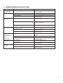
9 BREAKDOWNS AND SOLUTIONS
PROBLEM
Excessive and/or
abnormal noise
Excessive vibration
POSSIBLE CAUSE
Internal problem
Seeping of lubricant
from seals
Seals worn or damaged
Excessive heat
Gearbox not installed correctly
Weak coupling structure
Internal problem
Seals stiffened after prolonged time in storage
Clean the area and check for seeping after a
few hours of operation
Damaged seats
Restore the seats
Lack of lubricating oil
Apply lubricating oil
High thermal power
Contact the DINAMIC OIL S.p.A. technical
assistance service.
Contact the DINAMIC OIL S.p.A. technical
assistance service.
Check the coupling between the motor and the
gearbox
Insufficient lubrication
With the motor
switched on, the
slow shaft of the
gearbox
does not turn
Motor not fitted correctly
Parking brake will
not release
Lack of pressure
Jammed brake
Internal problem
Internal problem
Parking brake will
not apply
SOLUTION
Contact the DINAMIC OIL S.p.A. technical
assistance service.
Check the fastening
Strengthen the structure
Contact the DINAMIC OIL S.p.A. technical
assistance service.
Contact the DINAMIC OIL S.p.A. technical
assistance service.
Residual pressure in brake
Worn plate
Check the hydraulic circuit
Contact the DINAMIC OIL S.p.A. technical
assistance service.
Check the hydraulic circuit
Contact the DINAMIC OIL S.p.A. technical
assistance service.
Check the hydraulic circuit
Contact the DINAMIC OIL S.p.A. technical
assistance service.
76
10 DISMANTLING AND DISPOSAL
Before scrapping the gearbox, it needs to be rendered unusable and emptied of lubricant, remembering that used oil
has a serious impact on the environment.
The gearbox must be dismantled by expert operators, adhering to the applicable laws on occupational health and
safety and environmental protection.
Non-biodegradable products must not be disposed of into the environment under any circumstances.
Disassembled and disused gearboxes produce the following waste: iron, aluminium, cast iron, lubricant, plastic,
copper and bronze.
The gearbox parts must be disposed of according to the selective sorting standards in force in the country where the
disposal takes place.
For countries in the European Community, with the issue of Commission decision 2000/532/EC, subsequently
amended by decisions 2001/118/EC and 2001/19/EC from the Commission and 2001/573/EC from the Council, new
community provisions have been introduced regarding waste classification.
Do not attempt to reuse parts or components which may seem to be complete after they have undergone
checks and tests and/or replacements by specialist personnel and declared no longer fit for use.
77