1
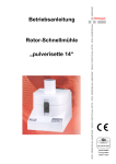
Operating Manual Variable Speed Rotor Mill "pulverisette 14" Fritsch GmbH Manufacturers of Laboratory Instruments Industriestraße 8 D - 55743 Idar-Oberstein - Germany Phone: Telefax: E-Mail: Internet: +49 (0)6784/ 70-0 + 49 (0)6784/ 70-11 [email protected] http://www.FRITSCH.de Fritsch GmbH, Laboratory Machines was awarded certification on 24 June 1994 by the TÜV-Zertifizierungsgemeinschaft e.V. Proof of fulfilment of the requirements of DIN EN ISO 9001 by Fritsch GmbH was given by means of an audit. The enclosed attestation of conformity outlines the standards which the high-speed rotor mill "pulverisette14" fulfils in order to carry the CE symbol. Instrument number 14.3000.00 Valid for serial number 1001 Edition 01/2005 Index 001 checked and released Table of contents Page 1 General / Introduction..............................................................1 1.1 1.2 1.3 Operating manual instructions.............................................................. 1 Explanation of the symbols used on the machine and in the operating manual ........................................................................ 2 Short description of the machine.......................................................... 3 1.3.1 1.3.2 1.3.3 Areas of application ......................................................................................... 3 Operating procedure ........................................................................................ 4 Drive motor and speed control ......................................................................... 4 1.4 Technical data ...................................................................................... 5 2 Operational safety....................................................................6 2.1 2.2 2.3 2.4 2.5 General safety instructions................................................................... 6 Operating personnel ............................................................................. 7 Safety equipment.................................................................................. 7 Hazard points ....................................................................................... 8 Electrical safety .................................................................................... 8 3 Installation ................................................................................9 3.1 3.2 3.3 3.4 3.5 3.6 Unpacking............................................................................................. 9 Transportation ...................................................................................... 9 Setting up.............................................................................................. 9 Ambient requirements .......................................................................... 9 Electrical connection........................................................................... 10 Initial switch-on / performance check ................................................. 11 4 Working with the mill .............................................................12 4.1 4.2 4.3 4.4 4.5 4.6 4.7 4.8 4.9 4.10 4.11 4.12 4.13 Impact rotor ........................................................................................ 12 Sieving ring ......................................................................................... 13 Inserting the grinding components ..................................................... 14 Grinding .............................................................................................. 15 Removing the milling parts ................................................................. 16 Grinding with collecting basin with outlet and retrofitting kit............... 16 Grinding with external cooling ............................................................ 17 Grinding with non-ferrous grinding set ............................................... 17 Continual feeding of grinding material................................................ 18 Grinding with the impact rotor insert................................................... 19 Grinding with the retrofitting kit for pin mills ....................................... 19 Influencing factors during grinding ..................................................... 20 Control panel ...................................................................................... 20 5 Cleaning ..................................................................................21 5.1 5.2 Cleaning the grinding chamber .......................................................... 21 Cleaning the intake filter ..................................................................... 21 6 Maintenance ...........................................................................22 6.1 6.2 6.3 6.4 Drive motor ......................................................................................... 22 Safety.................................................................................................. 22 Electronics .......................................................................................... 22 Machine .............................................................................................. 22 7 8 9 Warranty..................................................................................23 Checklist for rectifying faults................................................23 Examples ................................................................................24 „pulverisette 14“ 1 General / Introduction 1.1 Operating manual instructions • The copyright of these technical documents belongs to Fritsch GmbH, Laboratory Instruments. • Reprinting and reproduction of this operating manual is only allowed with the permission of Fritsch GmbH, Laboratory Instruments. • Study the operating manual carefully. • Operating personnel must be acquainted with the contents of the operating manual. • Please follow the safety instructions. • The high-speed rotor mill has been designed with operational safety in mind, however residual dangers cannot be ruled out. The instructions in this manual must be followed in order to avoid injury to the operators. • The symbols on the right-hand side indicate the hazards mentioned in the text. • Some symbols can also be found on the machine itself and warn of possible risks. Warning symbols are indicated by a surrounding triangle. • This operating manual is not a complete technical description. Only elements required for operation and service maintenance are described. „pulverisette 14“ page 1 Caution ! Pay attention to operating manual 1.2 Explanation of the symbols used on the machine and in the operating manual Danger! Warning of hazardous point Pay attention to operating manual Danger! Mains voltage Danger! Risk of explosions Danger! Hot surface Danger! Flammable materials Use protective gloves! Use ear protection! Use eye protection! 1.3 „pulverisette 14“ page 2 1.4 Short description of the machine 1.4.1 Areas of application The "pulverisette 14“ is a high-speed rotor mill used for rapid crushing of soft to medium-hard samples such as, for example: plants drugs chemicals chemical pulp wood dragees fertilizers filling materials roots tablets foodstuffs chalk leaves textiles wheat kaolin needles spices leather feed pellets soils coal After embrittling with liquid nitrogen: artificial resin foils plastics (PVC, PP, PE) The extremely high-speed rotor mill enables crushing of tough or ductile, temperature sensitive samples. Even slightly greasy or damp samples can be crushed without embrittlement by "freezing". By adding liquid nitrogen, samples that are extremely difficult to grind (for example, soft PVC foils) can be brought to analysis fineness. A titanium rotor and sieve are used for "non-ferrous" grinding. Corresponding to that, the grinding chamber that is normally manufactured from rust-free chrome nickel steel is coated in PTFE, which is relatively resistant to abrasions. The grinding insert of pure titanium may only be used for “soft materials”. Hard substances damage the sieve ring. „pulverisette 14“ page 3 1.4.2 Operating procedure The rapid crushing effect of the high-speed rotor mill "pulverisette 14" results from the extremely high speed of the rotor, which is made of rust-free, hardened steel. With a peripheral speed of up to 92 m sec-1, its impact energy is in the same range as that of pin mills, which are known for their high grinding performance. In addition, the sharp-edged teeth of the rotor work in combination with the inserted sieve to cut the sample by shearing – similar to rapid running cutting mills. The ground sample is collected in a rust-free collecting basin or filter sack after passing through the sieve. The grinding material sample is fed into the grinding chamber via a hopper where it is projected outwards by the high speed of the rotor. Here it comes into contact with the impact rotor. It is then crushed and discharged through the sieving ring with a defined grain size into the collecting basin. A collecting basin with a flange-mounted filter sack (optional retrofitting kit) is used for larger amounts or for materials which are more sensitive to heat. The sample is cooled by a strong air current, resulting from the turbine-like effect of the rotor, and is directly discharged. The electromagnetic vibration dosing channel "laborette 24" is connected to the high-speed rotor mill for continuous dosage of a sample and the free end of the feed channel is placed over the entry hopper of the high-speed rotor mill. The feed amount can be controlled by the user manually, so that the correct sample amount for optimum crushing is always released. If an excessive amount of ground sample is added, the dosing channel is automatically switched off and then on again. 1.4.3 Drive motor and speed control A maintenance-free rotary current is used for the drive motor, which is operated via a frequency converter. The speed of the rotor can be pre-selected in increments of 1000 rpm in the range of 6000-20000 1/min by pressing the keys marked (+) or (-), allowing it to be adapted to the requirements of the sample grinding. The speed is adjusted according to each load situation. „pulverisette 14“ page 4 1.5 Technical data Dimensions and weight Dimensions: 431 x 310 x 478 mm (height x width x depth) Weight: 23 kg (net) 26 kg (gross) Working noise The noise level equals up to approx. 85dB (A). The value fluctuates greatly depending on the speed and grinding material as well as sieving ring perforation and number of rotor ribs. The noise level rises above 90db (A) if an open system is used such as the flange-mounted filter sack. In this case, a louder noise can be heard caused by the flowing air current. Voltage The machine can be operated at two levels of voltage: • single-phase alternating voltage 100-120V ± 10% as well as • single-phase alternating voltage 200-240V ± 10%. Transient excess voltages are permissible in accordance with overload voltage category II. (see also chapter on 3.5 Electrical connection) Current consumption The maximum power consumption is approx. 10 A. Power consumption The maximum power consumption is approx. 1kW. Electric fuses • Fuse-link at the back on the machine (mains voltage supply): 2 x10 A T • Fuse-link at the back of the machine 2 x 0.4AT Material • Feed particle size maximum approx. 10 mm • Feed amount maximum 200 ml Final fineness The final fineness depends on the inserted sieving ring and is between 0.08 mm and 6.0 mm. „pulverisette 14“ page 5 2 Operational safety 2.1 General safety instructions • Read the operating manual carefully. • The high-speed rotor mill may only be used for the purposes described in chapter 1.4.1 Areas of application. • We recommend that a safety logbook should be kept in which all work (service, repairs etc.) carried out on the machine should be entered. • Use only original accessories and original spare parts. The safety of the machine is impaired if this instruction is not followed. Read operating manual carefully. • Do not continue to use damaged accessories. • Operating personnel must be acquainted with the contents of the operating manual. For this reason it is essential that – among other things - the operating manual is kept near the machine at all times. • When open, the protection level of the machine is IP 20, which means that water and particles <12mm can penetrate within the machine. When cleaning (see chapter 5 Cleaning) and removing the milling parts (see chapter 4.5 Removing the milling parts), attention should be paid to this point. • Do not remove instructive labels or signs. • Do not deactivate safety devices. • Unauthorised changes to the machine lead to the loss of Fritch’s attestation of conformity to European directives as well as the loss of the warranty. • Wear protective gloves! The collecting basin and the grinding components can be very hot after grinding. Grinding parts such as rotors and sieves or the collection container may have sharp edges. Safe and undamaged gloves must be worn during cleaning work in particular. To avoid the risk of cutting oneself on the sieve rings, sieves with reinforcement rings can be used. These have no sharp metal edges. Wear protective gloves! Wear protective glasses! • Wear protective glasses! Excess pressure can build up during grinding with liquid nitrogen. Danger of splashing! All other laboratory regulations concerning handling of liquid nitrogen must be followed and only specially trained personnel may do this work. • Wear ear protection! The noise level is above 85dB(A) • Do not allow the high-speed rotor mill to grind for more than half an hour without cooling phases. Danger of overheating! • Operating personnel must always operate the machine with safety in mind. • All threshold limit values according to current safety requirements must be followed; if necessary, a ventilator must be provided or the machine must be operated under an extractor outlet. „pulverisette 14“ page 6 Wear ear protection • When grinding oxidable materials (e.g. metals or coal), there is a risk of instantaneous combustion (dust explosion) if the material exceeds a certain fineness. The fine material can be absorbed through a filter in the back of the machine and could ignite on electric components. It is therefore necessary to take special safety precautions when grinding such material and the work must be supervised by a specialised person. • When grinding electrically conductive materials, the fine dust can be absorbed by the filter in the back of the machine and cause short circuiting. It is therefore necessary to take special safety precautions and to pay special attention to cleanliness when grinding such material. • The high-speed rotor mill is not explosion protected and is not designed to grind explosive materials. • Do not run the high-speed rotor mill unsupervised. 2.2 Operating personnel • • 2.3 The high-speed rotor mill may only be operated by authorised personnel and maintenance and repairs may only be carried out by trained specialists. People with health problems or under the influence of medication, drugs, alcohol or exhaustion must not operate the high-speed rotor mill. Safety equipment Safety equipment must be used in accordance with the regulations and must not be rendered inoperative or be removed. All safety equipment must be checked regularly for completeness and function, see the chapter 6 Maintenance on. The hood must be closed for operation. The hood is locked: • when the machine is disconnected • during operation The hood can only be opened when the mill's drive motor has come to a standstill. „pulverisette 14“ page 7 Danger: risk of explosion Opening the hood when disconnected from the power supply 1. Pull out the plug and unscrew the entire connecting terminal plate with filter unit in the back (7 screws). Open lock with a male triangular wrench by turning to the right. 2. The hood can now be opened. 3. Now the high-speed rotor mill cannot be switched on. To do so, the safety lock must be activated by a left-hand turn of the male triangular wrench and the hood closed. The motor can only be activated when the lid lock is closed by pressing the [ START ] - switch. When the [ STOP ] - switch is pressed, an electronic brake brakes the motor within approx. 1015 seconds. You can only open the hood once the hood lock has been released by the motor's speed sensor. 2.4 Hazard points • • • • • 2.5 Risk of crushing when closing the hood! Risk of crushing when removing and installing the collecting basin! Collecting basin can get very hot! Never operate the machine without sieving ring, collecting basin and lid. If a sieving ring is not desired, the sieving ring substitute no. 44.1110.00 must be used. Danger of cutting oneself on grinding parts such as rotors and sieves or the collection container. These may have sharp edges. To avoid the risk of cutting oneself on the sieve rings, sieves with reinforcement rings can be used. These have no sharp metal edges. Electrical safety General • The main switch disconnects the machine from the mains via two pins. • Switch off the mains switch if the high-speed rotor mill is "out of operation" for a longer period of time (e.g. over night). Protection against restart Following a power failure during operation or after the mains switch has been switched off, the hood is locked. Once the power supply returns, the hood lock is opened. However, the highspeed rotor mill does not resume operation for safety reasons. Overload fuse (see Checklist for rectifying faults) One of the tasks of the microcontroller is to monitor power consumption of the motor and to switch off the motor after 10 seconds of overload. The motor is started by pressing the [ START ] switch after rectifying the fault. In the event of excessive heating of the drive motor, the machine switches off. The machine switches off if the drive is blocked. „pulverisette 14“ page 8 Caution! 3 Installation 3.1 Unpacking • Pull out the nails which fix the hood to the transport pallet. The hood is either a wooden box or a cardboard carton, which has been slipped over the transport pallet. • Lift the hood from the transport pallet. • Compare the contents of the delivery with your order. 3.2 Transportation • To carry, grip under the housing edge. 3.3 Setting up Place the high-speed rotor mill on an even, stable surface. It is not necessary to fix it in place. You can adjust the height of the rubber feet of the high-speed rotor mill in order to balance out any unevenness. • Take care that the high-speed rotor mill is easily accessible. There must be sufficient room for the mains switch on the back of the machine to be reached. • Keep the air inlet via filters in the back and air outlet via air ducts on the sides free. Danger of overheating! 3.4 Ambient requirements • The machine may only be operated indoors. • The surrounding air must not contain electrically conductive dusts. • Room temperature must be between 5 - 40°C. • Height up to 2000m sea level • Maximum relative humidity 80% for temperatures up to 31°C, linearly decreasing to 50% relative humidity at 40°C. • Contamination grade 2 in accordance with IEC 664. „pulverisette 14“ page 9 Danger: mains voltage 3.5 Electrical connection Before connecting the high-speed rotor mill, check the voltage set by the voltage selector switch at the back of the machine with the values of your mains power supply. The slit in the switch shaft must point to the voltage value of the mains power supply in question. 100-120 and 200-/240 V alternating current with protective conductor; fuse max. 16 A Before connection, compare the voltage and current indicated on the serial plate with the mains power supply in question. Single-phase alternating voltage with protective conductor (see chapter 1.5 Technical data). Changes or adjustments to the connecting cable may only be carried out by assigned specialists. „pulverisette 14“ page 10 3.6 Initial switch-on / performance check The machine may be switched on only after all work described in the chapter 3 on Installation has been carried out. To switch on 1. Connect the machine to the mains power supply. 2. Switch the machine on using the power switch at the back of machine. 3. The displays light up, the electric lock is opened shortly afterwards. 4. Grip under the lock latch and pull forward; open hood. 5. Lift up the lid of the grinding basin. 6. Remove the sieve and rotor. 7. Remove the collecting basin and place it on a flat surface. 8. Close hood. 9. Set speed to 6000 rpm on the control panel. 10. Press START on control panel. 11. The hood is locked electrically and the mill runs at the preselected speed. 12. Increase speed up to 20000 rpm with (+) key and decrease it to again to 6000 rpm with the (-) key. To switch off 1. Press STOP switch on control panel 2. After a short period of time (after the mill has come to a standstill), the hood can be unlocked and opened. „pulverisette 14“ page 11 4 Working with the mill 4.1 Impact rotor The impact rotors are made of rust-free, hardened special steel – the 12-rib-rotor is available in pure titanium as a special accessory for non-ferrous grinding. (A rotor with 12 ribs has proven itself as a standard rotor in many cases.) 8-rib-rotor The rotor with 8 ribs enables rapid fine grinding of materials with feed material grain size < 25 mm (longest length) or of fibrous material (order no. 44.4080.10). You can remove the interior hopper to feed in the material to be ground. The 8-rib-rotor is also suitable for pre-crushing (or coarse crushing). To do so, it is operated with the sieving ring substitute (no. 44.1110.00) and possibly without the interior hopper as well. 12-rib-rotor The rotor with 12 ribs enables rapid fine grinding of materials with feed material grain size < 15 mm (longest length). (Special steel: order no. 44.4120.10; titanium: order no. 44.4120.32) You can remove the interior hopper to feed in the material to be ground. This rotor is also suitable for pre- or coarse crushing. 24-rib-rotor The rotor with 24 ribs (order no. 44.4240.10) enables rapid fine grinding of all materials with feed material grain size < 5 mm (longest length). When using the retrofitting kit (order no. 14.3510.00), this rotor offers the highest air throughput, speeding up grinding, improving cooling and therefore helping protect heat-sensitive material to be ground. „pulverisette 14“ page 12 4.2 Sieving ring The final fineness of the ground material is determined by the choice of sieving ring. For available sieving ring sizes, see service manual. As a rule, the final fineness of the ground material depends on the diameter of the holes indicated by the sieving ring. In normal cases, use the sieving ring with trapezoidal perforation, the directional arrow displayed on it pointing upwards Ï. In this case, particles can be found in the ground material which are larger than determined by the hole diameter. If you would also like to achieve a high fine percentage, insert the sieving ring with the directional arrow pointing down Ð. In this case, the standard is that approx. 2/3 of the feed material is ground finer than 1/2 of the hole diameter. When grinding without a sieving ring, the sieving ring substitute (44.1110.10) must be used so that the distance between the lid and the rotor is ensured. „pulverisette 14“ page 13 4.3 Inserting the grinding components 1 2 3 4 5 6 motor Labyrinth disk rotor sieve ring collecting pan lid for collecting pan Assemble the grinding parts in the device in the following order: 1. Place the collecting pan (5) on the labyrinth disk (2). The labyrinth disk is clamped and centered with an o-ring, which is to be pressed down firmly until the level of the labyrinth disk rests on the motor flange. 2. Now insert the rotor (3) (see chapter Fehler! Verweisquelle konnte nicht gefunden werden. Fehler! Verweisquelle konnte nicht gefunden werden.). Guide the rotor on the motor shaft in such a manner that the countersunk groove at the lower end of the rotor shaft points in the direction of the levelled side of the motor shaft. Warning! Do not tilt while setting up on the motor shaft. The rotor must glide lightly on to the motor shaft and it should be possible to turn it after setting it up (possibly grease a little). 3. Insert the sieving ring (4) (see chapter Fehler! Verweisquelle konnte nicht gefunden werden. Fehler! Verweisquelle konnte nicht gefunden werden.). If no sieving ring is desired, use the replacement for sieving ring with order no. 44.1110.10. 4. Close it completely with the lid (6) (the center disk should be centered on the sieving ring in the center of the lid). 5. Now close the hood of the device and fasten the entire assembly with the clamping lock. The clamping lock must offer a fair amount of resistance when closed and must snap in place. The hood now presses with the sealing ring around the feed funnel onto the centring disc in the lid of the collecting basin. This pressure is transferred via the sieving ring to the labyrinth seal so that the sieving ring and the labyrinth seal are held tightly in place. „pulverisette 14“ page 14 The resistance when closing the clamping lock determines the pressure with which the sieving ring is held in place. If the clamping lock cannot be closed, the centring disc in the lid of the collecting basin is not central on the sieving ring. This can be corrected by moving the lid to one side. When the grinding material is no larger than 8 mm, the accompanying small interior hopper (order no. 14.2480.10) with an internal diameter of 13mm can be inserted. This leads to a strong reduction in air noises. Other interior hoppers with 10mm (order no. 14.2470.10) and 20mm (order no. 14.2490.10) internal diameters can be inserted. The smaller the internal diameter, the lower the noise levels when grinding. Caution: when opening the hood, the small interior hopper can fall out to the rear when the hood is fully opened. The machine may only be operated when all parts have been fitted. If parts are forgotten, damage to the machine can result. 4.4 Grinding After you have closed the high-speed rotor mill as described under 4.3 paragraph 0, you can continue as follows. 1. Switch on the machine using the main switch on the back. 2. Set the desired speed by pressing the (+) or (-) buttons 3. Press the button [ START ] the high-speed rotor mill starts up. 4. Wait until the mill has warmed up to the selected speed. 5. Carefully feed the grinding material in small quantities into the hopper 6. Once grinding is completed, press the [ STOP ] button. 7. Once the motor has come to a standstill, open the clamping lock and the hood. „pulverisette 14“ page 15 4.5 Removing the milling parts 1. Lift up the lid and use a brush to brush the grinding material off the rotor and from the inner edge of the collecting basin to the outside. This prevents the grinding material from falling down into the device through the central cooling operning. If grinding material nevertheless falls in, it does not immediately land in the device, but must still be sucked away with a vacuum immediately after removal of the sample (see section 5.1 Cleaning the grinding chamber). 2. Remove the collecting basin with sample. 3. Remove the sieving ring and rotor Important: It is important that the sieving ring and rotor are removed only after removing the sample because incompletely fragmented sample may still be present on both parts. This could in some circumstances mix with the ground sample and compromise the grinding results. 4. Remove the labyrinth disk. Since the labyrinth disk is clamped and centered with an o-ring, it may offer some resistance while removing. 5. Clean the parts before the next grinding (see section 5.1 Cleaning the grinding chamber). 4.6 Grinding with collecting basin with outlet and retrofitting kit The retrofitting kit for large quantities order no. 14.3510.00 (see service manual) is made up of: • Collecting basin with outlet, • Tensioning ring with tube bend, • Nylon support bag and • Paper filter bag We recommend the use of the retrofitting kit when you 1. want to grind larger quantities: As a result of the centrifugal effect of the impact rotor and the increased air throughput the grinding material is output and collected in the filter bag, or when you 2. want to grind temperature-sensitive materials: The increased air flow cools the grinding material and the time for grinding, and with it the dwell time of the material in the grinding chamber, is reduced. The high-speed rotor mill is set up as described under point 4.3 Place the paper filter in the nylon support bag and clamp it with the tensioning ring on the plastic flange. Place the tube bend up to the stop in the plastic part on the collecting basin. An O-ring in the plastic part seals off the tube. For easier assembly the end of the tube can be coated with some soap or oil. The tube must be pointing horizontally to the left and must fit through the opening on the left-hand side of the hood. First, it may be necessary to remove the small cover plate on the left-hand side of the hood. „pulverisette 14“ page 16 4.7 Grinding with external cooling With certain grinding materials, the crushing process can be favourably influenced by applying cooling agents before grinding, e.g. animal body parts or special plastics can be made brittle by dipping them in liquid nitrogen or freezing them in the deepfreezer before grinding. The grinding material should be protected against condensation water – e.g. a PVC bag could be used to keep the grinding material dry during cooling and before grinding. For grinding materials that are especially sensitive to temperature changes, we recommend additional cooling using liquid nitrogen. This can be added directly to the grinding material in the feed funnel. Caution: When using liquid nitrogen or dry ice: wear protective glasses and suitable thermal gloves Observe all regulations relating to the use of liquid nitrogen Caution: When grinding larger quantities (> 20 g) with external cooling, you must always use the retrofitting kit. You can also use so-called dry ice (solid carbon dioxide) for cooling. You should remember, however, that dry ice often contains frozen condensation water on the surface, which, amongst other things, can clog up or contaminate the sieving ring. 4.8 Grinding with non-ferrous grinding set If you must avoid even the smallest amount of iron during grinding, use the non-ferrous grinding set (order no. 14.3700.00). The set consists of • a 12-rib-rotor made of titanium (99.8% titanium), • a sieve insert 0.5 mm, made of titanium, • a collecting basin coated with PTFE and • a lid coated with PTFE. Simply interchange the collecting basin and lid. However, when using the non-ferrous grinding set, remember that the hardness and abrasion resistance of titanium is considerably lower than that of hardened special steel. The Teflon coating of the collecting basin and lid also only offers reduced resistance. (Point 1.4.1) The trumpet-shaped interior hopper made of stainless steel must be removed. „pulverisette 14“ page 17 4.9 Continual feeding of grinding material Use the vibration dosing channel "laborette 24" for feeding larger amounts of pourable material. Place the dosing channel on a stand next to the high-speed mill, so that the channel end is over the hopper. For electricity supply, connect the vibration dosing channel to the socket on the back of the high-speed mill. If the motor is overloaded, feeding is interrupted and automatically switched on again when the material has been pro-cessed and the motor is running at rated load again. The flow of the grinding material to the channel is set using the dosing channel control. The material flow from the hopper onto the feed channel of the "laborette 24" must be adapted to the material's flowing characteristics. Adjust the distance between the hopper and the channel by sliding the hopper up and down, so that the "correct" amount is fed. If too much material is supplied, the feed channel's automatic cut-out switches off too often; in this case, slide the hopper down slightly. If too little material is supplied, the load display constantly remains in the lowest range; in this case, slide the hopper slightly up. The connecting plug "L24-II“ on the back of the machine is for operation of future generations of dosing channels. „pulverisette 14“ page 18 4.10 Grinding with the impact rotor insert In order to carry out a grinding procedure similar to the one in a hammer bar mill, an insert with impact blades and outlying sieving ring with 1.0 mm trapezoidal perforation is available.(See service manual spare parts list 14.3850.00) The rotor with its 8 teeth runs closely next to the beater blades, which heightens the shearing effect on the material. This causes more rapid coarse crushing of dry materials. The temperature load of the materials is also considerably decreased during fine grinding. The best results were achieved during grinding experiments with the 8-rib-rotor and a 1.0 mm sieving ring, but any other, possibly already existing, rotor can be used. You can find other sieve sizes as well in the spare parts list 14.3850.00 in the service manual. If you would like to use an already existing rotor, you only need to order the beater blade insert 44.1121.10 and a matching sieving ring from the spare parts list. Caution: the normal sieving rings do not fit !! Use of the impact rotor insert is the same as for normal grinding tools. The sieving ring is only substituted by the impact rotor insert with outlying sieving ring. The O-ring seals the sieving ring against the lid of the collecting basin. First, the sieving ring is pulled over the impact rotor insert and then the O-ring is pressed into the groove. The 12-rib-rotor or 24-rib-rotor can be used as well as the 8-ribrotor. You can find the order numbers of the various sieving rings on the spare parts drawing. 4.11 Grinding with the retrofitting kit for pin mills With the help of this retrofitting kit, the rotor mill can be converted into a sieveless pin mill. However, in order to ensure the distance and centring between rotating and fixed pin disc, a spacer (substitute for sieving ring) must be fitted. Assembly can be seen in the spare parts drawing 14.2600.00. The equipment is used in the same way as for a normal rotor or impact rotor insert. The pin mill works best of all as an open system with the retrofitting kit for larger amounts no. 14.3510.00. But it functions as a closed system with a normal collecting basin as well. „pulverisette 14“ page 19 4.12 Influencing factors during grinding Feeding material to be ground The smaller the dosage of fed material is, the higher the fine fraction and grinding time. Mechanical and temperature loads of the mill are reduced. Speed Higher speeds reduce grinding time and increase the fine fraction. The mechanical and temperature loads of the mill increase exponentially with high speeds. Hole size of the sieves The finer the sieve perforation is, the longer the grinding time; finer perforation reduces the noise level. Cooling Good cooling (e.g. by using the filter system or material suction) always has a positive effect on grinding and mill. 4.13 Control panel - When the mill is switched on, the display value of the last grinding process appears - Timer: Range "P“, "1“-"99“ min, whereas "P“ represents permanent operation - Speed: Range "6“-"20“ (x1000 rpm), can be set in increments of 1000 - Load: lights up when the motor is overloaded with too much material - Temperature: switched off when in the normal range - It flashes when temperatures are increased; the current grinding procedure can be completed; a new start is only possible after a cooling period - It is permanently lit when temperatures are excessive; the motor is switched off. - If the temperature sensor is not functioning correctly, it is permanently lit as soon as the mill is switched on. „pulverisette 14“ page 20 5 Cleaning 5.1 Cleaning the grinding chamber The type and frequency of thorough cleaning depends on the materials to be ground and their final fineness. We recommend adapting the cleaning intervals to the use of the high-speed rotor mill following regular inspections in the beginning. You must carefully and completely remove any material residue under the labyrinth seal and in the area of the motor bearings – if necessary, use a paint or vacuum cleaner brush. You must thoroughly clean the collecting basin, rotor, sieve and labyrinth seal outside of the high-speed rotor mill – they may be brushed down with water or cleaned in the ultrasonic bath "laborette 17". For cleaning the interior hopper can be removed by turning and moving up. For remount do the same in inverse order. When cleaning the grinding components, take care to clean all guide surfaces with sliding movements. These surfaces can also be lightly greased. Caution while cleaning the grinding parts: The rotor and sheet metal parts such as sieves and the collection container may have sharp edges. Safe and undamaged gloves must be worn. To avoid the risk of cutting oneself on the sieve rings, sieves with reinforcement rings can be used. These have no sharp metal edges. 5.2 Cleaning the intake filter The intake opening for machine cooling air at the back of the high-speed mill is protected by a filter mat, so that only relatively dust-free cooling air is drawn into the machine. Maintenance of this intake filter is vital for the life of the machine! Inspect the intake filter regularly and if necessary, rinse it under running water or replace it with a new one. A contaminated, clogged up intake filter can damage the drive motor as a result of insufficient cooling. „pulverisette 14“ page 21 6 Maintenance 6.1 Drive motor The three-phase motor does not require maintenance. 6.2 Safety 6.3 Before starting work, check the tumbler and, in particular, the slit for the actuator for dirt or soiling. Always keep the tumbler clean and free from dust. Check that the actuator fits correctly into the tumbler. Before starting work, open the hood until the actuator is no longer engaged in the tumbler and simulate a start test with open hood. If the machine does start, switch off at once, decommission the machine and renew the tumbler. Electronics The electronics do not require maintenance. 6.4 Machine Apart from regular cleaning, the machine requires no servicing. The bearings of the rotating components are equipped with permanent lubrication. The most important aspect of maintenance is regular cleaning: The entire machine must be cleaned in line with the regulations of the employer's insurance association against occupational accidents (VBG 4) – in particular when the machine is being operated in a dusty environment or when dusty grinding material is being processed. Before beginning maintenance work, remove the mains plug and secure the machine to prevent it being switched on again unintentionally! Put up a warning sign to indicate that maintenance work is being carried out. Function Task Test Safety lock Hood lock Is the closed hood held Each time closed when the main switch before use is off? Drive motor Permanent lubrication Bearing play After 4000 hrs. or once a year Fan, filter mats Cooling of grinding chamber and electronics Function, clean when clogged 2 x each year „pulverisette 14“ Service interval page 22 Danger! Mains voltage 7 Warranty The warranty card accompanying this delivery must be completely filled in and returned to the supplier in order for the warranty to come into force. The company Fritsch GmbH, Idar-Oberstein and its "Application Technology Laboratory" or the corresponding state representatives will gladly offer help and advice. It is necessary to name the serial number imprinted on the nameplate with any enquiries. 8 Checklist for rectifying faults Fault Displays do not light up POWER SUPPLY does not light up START button is pressed but mill fails to start Mill comes to a standstill Hood cannot be opened Grinding material emitted Noisy running with heavy vibrations „pulverisette 14“ Possible cause No mains connection Remedy Connect mains plug Main switch off Machine fuses blown Switch on main switch Check machine fuse Fuse insert on back of machine 2 x 10 A T and 2 x 0.4 A TT Allow mill to cool down Machine overheated Safety lock has been opened manually Electrical fault on machine Shut down due to thermal overloading of the drive Drive blocked See chapter 2.3 on Safety equipment Contact customer service Leave the machine to cool down and select a lower speed Rectify fault in grinding chamber Speed sensor defective Contact customer service Mains connection is Insert mains plug missing Main switch Switch on mains switch Machine fuse Check machine fuse Fuse insert on back of machine 2 x10 A T Sealing ring defective Clean or replace sealing or dirty ring Motor bearing defect, Check motor and grinding balance on grinding rotor rotor page 23 9 Examples The following examples from the Applications Lab at Fritsch GmbH provide instructions on combining grinding fixtures and on the optimum use of the high-speed rotor mill. Grinding material Qty. (gr.) Rotor Polyvinyl alcohol 20g 12 0.12 Trapez. 2 Polyvinyl alcohol 50g 12 1.00 Trapez. 1 Polyester yarn 4g 12 4.00 Round 1 Teflon (2 mm) 500g 24 0.50 Trapez. 20 Rubber granule 10g 12 1.00 Trapez. 5 Glass fibre 10g 8 0.12 Trapez. 2 Wool felt 30g 12 1.00 Trapez. 2 Cotton 25g 8 0.50 Trapez. 5 Almonds 60g 12 1.00 Trapez. 1 Almonds 80g 12 2.00 Round 3 Corn 15g 12 1.00 Trapez. 3 Corn 140g 12 1.00 Round 3 Cocoa 600g 8 6.00 Round 5 Hops 35g 12 0.20 Trapez. 5 Carrots 50g 24 1.00 Trapez. 2 Dried plants 30g 12 0.08 Trapez. 15 Bones 10g 12 1.00 Trapez. 0.5 Calf teeth 20g 12 1.00 Trapez. 3 Pellets 50g 12 0.20 Trapez. 2 Plaster 250g 12 0.50 Trapez. 2 Fertilizers 800g 24 0.50 Trapez. 20 Phosphate 200g 24 0.12 Trapez. 10 Coke 200g 8 1.00 Round 3 Aluminium oxide 20g 12 0.50 Trapez. 0.3 Sediment 50g 12 0.20 Trapez. 2 Sludge(dry) 10g 24 0.20 Trapez. 3 „pulverisette 14“ Sieve ring Time (min.) page 24