1
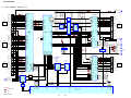
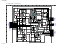
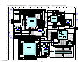
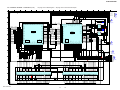
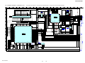
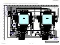
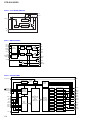
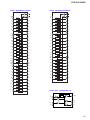
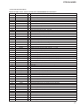
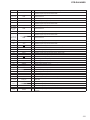
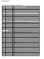
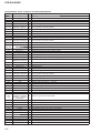
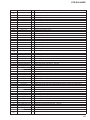
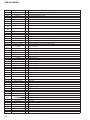
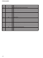
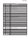
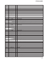
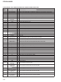
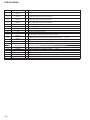
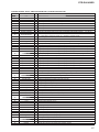
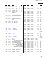
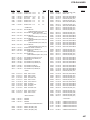
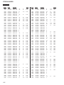
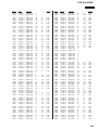
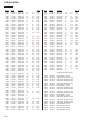
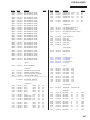
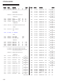
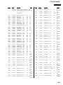
STR-DA5400ES
DSP BOARD IC5208 MB91F353APMT-GE1 (DSP CONTROLLER)
Pin No.
Pin Name
I/O
Description
PCM audio signal (digital input) input from the digital audio interface receiver or HDMI receiver
1
RDATA0
I
2 to 8
-
-
Not used
9
DSP2_SIB_SEL
O
Data selection signal output to the data selector
10
P_ERROR
I
PLL lock error signal and data error flag input from the DSP1
11
DSP1_SPIDS
O
Serial data latch pulse signal output to the DSP1
12
DSP1_RESET
O
Reset signal output to the DSP1 and flash memory
13, 14
DSP1_BOOTCFG0,
DSP1_BOOTCFG1
O
Boot mode setting signal output to the DSP1
15, 16
-
-
Not used
17
SF2_DSP2_MAS
I
Master/slave mode selection signal input from the DSP2
18, 19
-
-
Not used
20
SF2_CPU_CE
O
Chip enable signal output to the serial flash
21
DSP2_SPIDS
O
Serial data latch pulse signal output to the DSP2
22
DSP2_RESET
O
Reset signal output to the DSP2
23, 24
-
-
Not used
25, 26
DSP2_BOOTCFG0,
DSP2_BOOTCFG1
O
Boot mode setting signal output to the DSP2
"L": reset
"L": reset
27 to 35
-
-
Not used
36
DRST_TRG
O
Programming end flag output to the system controller
37 to 39
-
-
Not used
40
VSS
-
41
SDA
I/O
Two-way I2C data bus with the system controller
Two-way I2C clock bus with the system controller
Ground terminal
42
SCL
I/O
43
VSS
-
Ground terminal
44
VCC
-
Power supply terminal (+3.3V)
45 to 47
-
-
Not used
48
RD
O
Read strobe signal output terminal
Not used
49
WR0
O
Write strobe signal output terminal
Not used
50, 51
-
-
Not used
Programming mode setting signal input from the system controller
52
MD2
I
53, 54
MD1, MD0
I
Programming mode setting signal input terminal
55
XRESET
I
Reset signal input from the system controller
Power supply terminal (+3.3V)
56
VCC
-
57
XOUT
O
System clock output terminal (12.5 MHz)
58
XIN
I
System clock input terminal (12.5 MHz)
59
VSS
-
Ground terminal
60 to 62
-
-
Not used
63
MD_BUSY
I
Busy signal input from the system controller
64
DM_BUSY
O
Busy signal output to the system controller
65
DM_INT
O
Interrupt request signal output terminal
66 to 69
-
-
Not used
70, 71
PN0, PN2
-
Not used
72 to 75
-
-
Not used
Not used
"L": reset
Not used
76
VSS
-
Ground terminal
77
VCC
-
Power supply terminal (+3.3V)
78 to 80
-
-
Not used
81
INT0
I
Interrupt request signal input terminal
82
MD_INT
I
Interrupt request signal input from the system controller
83
DSP1_INT
I
Interrupt request signal input from the DSP1
84
DSP2_INT
I
Interrupt request signal input from the DSP2
85, 86
INT4, INT5
I
Interrupt request signal input terminal
87, 88
-
-
Not used
89
MD_DATA
I
Serial data input terminal
90
DM_DATA
O
Serial data output terminal
91
SCK0
O
Serial data transfer clock signal output terminal
134
Not used
Not used
Not used
Not used
Not used