1
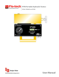
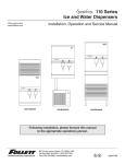
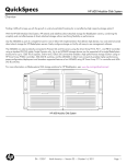
25 and 50 Series
Ice and Water Dispenser
Order parts online
www.follettice.com
Operation, Service and Parts Manual
Service Number 5024400 and Above
C25T5A/W
C25R5A/W
C50R5A/W
C50T5A/W
H25R5A/W
H25T5A/W
H50T5A/W
H50R5A/W
801 Church Lane • PO Box D, Easton, PA 18044
Toll free (800) 523-9361 • (888) 2-FOLLETT
(610) 252-7301 • Fax (610) 250-0696 • www.follettice.com
F255A/W
F505A/W
®
U® L
207933R03
Welcome to Follett
Follett ice dispensers enjoy a well-deserved reputation for excellent performance, long-term reliability and outstanding
after-the-sale support. To ensure that your dispenser delivers this high performance, we ask that you review the first two
pages of this manual to understand the operation and requirements of your new dispenser. Pages 4 - 11 are for use by
service technicians maintaining the unit. Should you have any questions or require technical help at any time, please call
our technical service group at (800) 523-9361 or (888) 2-FOLLETT or (610) 252-7301.
Operation
Before you begin
Check your paperwork to determine which model you have. Follett model numbers are designed to provide information
about the type and capacity of Follett ice dispensing equipment. Following is an explanation of model numbers:
C50T5A
2 3 4 5
1
!
1. Dispenser configuration – C = countertop, H = wall mount, F = freestanding
2. Approximate storage capacity in lbs
3. Icemaker location – R = remote icemaker; T = integral icemaker in top of cabinet.
Note: No letter is used to indicate icemaker located in base of freestanding units.
4. Icemaker capacity – 5 = 400 lbs/day, R22 refrigerant
5. Condenser type – A = air-cooled, W = water-cooled
Important cautions
• Dispenser bin area contains mechanical, moving parts. Keep hands and arms clear of this area at
all times. If access to this area is required, power to unit must be disconnected first.
• A Follett QC4-FL4S water filter system (order #AFSYSTMFL4S) in icemaker inlet water line is
recommended.
• Ice is slippery. Maintain counters and floors around dispenser in a clean and ice-free condition.
• Ice is food. Follow recommended cleaning instructions to maintain cleanliness of delivered ice.
• Countertop dispensers that sit on legs (not bolted to counter) can be inadvertently moved. Care should be
taken when operating and cleaning to avoid accidents.
Electrical specifications
Freestanding models and models with integral icemakers
Basic electrical
115/60/1 Total system 13.0 amps, max. fuse size 20 amps
Alternate electrical 230/50/1 Total system 6.8 amps, max. fuse size 15 amps
Models with remote icemakers
Models with remote icemakers require separate circuits and disconnects for icemaker and dispenser.
Basic electrical
115/60/1 Icemaker 11.0 amps, max. fuse size 20 amps
Dispenser 2.0 amps, max. fuse size 15 amps
Alternate electrical 230/50/1 Icemaker 6.0 amps, dispenser .8 amps, max. fuse size 15 amps each
All models must be hard-wired. Equipment ground required. Electric disconnects required within 10 ft (3m) of dispenser.
One disconnect each for dispenser and icemaker for all 25/50 series dispensers with remote icemaker.
Ambient specifications
Air Temp
Water Temp
Water Pressure
100° F/38°C Max.
90°F/32°C Max.
70 P.S.I. Max.
50°F/10°C Min.
40°F/4°C Min.
10 P.S.I. Min.
Plumbing
C25/50 with
H25/50 with
C25/50 with
H25/50 with
F25/50
remote icemaker remote icemaker integral icemaker integral icemaker
Dispenser drain
3/4" FPT
3/4" ID
3/4" FPT
3/4" ID
3/4" FPT
Icemaker drain
1/2" MPT
1/2" MPT
–
–
3/8" FPT
Water inlet
1/4" FPT
1/4" FPT
3/8" FPT
3/8" FPT
3/8" FPT
Cond. inlet – w/c only
3/8" FPT
3/8" FPT
1/2" FPT
1/2" FPT
3/8" FPT
Cond. drain – w/c only
1/2" FPT
1/2" FPT
1/2" FPT
1/2" FPT
1/2" FPT
Note: Water shut-off recommended within 10 feet (3m) of dispenser.
Drain to be hard piped and insulated and maintain at least 1/4" per foot (6mm per 304mm run) of slope.
2
How the dispenser works
Follett’s 25 and 50 automatic load ice dispensers receive ice from Follett's 400 lb/day icemaker located in the
dispenser base, in the cabinet top or in a remote location up to 20 feet (6 meters) away. Ice produced is stored in the
bin section of the dispenser. On lever and push-button dispensers, when the dispense lever or button is pushed, the
ice dispense solenoid is energized. This opens the gate and activates the dispense motor, causing the wheel to turn.
This moves ice to the dispense chute where it drops by gravity into the container held below the chute.
In Follett’s continuous icemaking process, water freezes to the inside walls of the evaporator. A rotating stainless
auger carries the ice to the top of the evaporator where it is compressed and extruded through an outlet port. The ice
is then pushed through a tube to the dispenser bin. When the storage area is full, a bin stat opens and shuts the
icemaker off.
A level fill circuit maximizes the fill in the bin by rotating the wheel at intervals until the bin is completely filled. When
the bin is filled, a bin stat shuts off the icemaker to avoid overfilling the bin. The icemaker will restart after 20 min. if the
bin is calling for ice.
How the SensorSAFE™ accessory works
Follett’s SensorSAFE accessory maximizes sanitation and minimizes the possibility of cross-contamination by
eliminating physical contact between the cup or container and dispenser. Sensors in the panel use reflected infra-red
light to detect the presence of the container and send a signal to a control board which then activates the appropriate
components for ice or water dispensing. The SensorSAFE package includes a cleaning switch under the left side of
the front cover which temporarily shuts off dispensing to allow cleaning of the panel and lenses. If the switch is not
turned back on after cleaning, the dispenser automatically resets after two minutes for normal operation. SensorSAFE
also includes a time limit safety feature which automatically stops ice dispensing after one minute of continuous
dispensing. Dispensing can be resumed by moving the container away from the dispenser and returning it to the
activation zone.
How the chilled water accessory works
Follett’s chilled water accessory uses ice from the dispenser’s storage hopper to chill incoming water supplied to the
water station. The water chiller assembly is located in the dispenser cabinet under the storage hopper. As ice is
dispensed, or the wheel motor is energized during the level fill cycle, ice is automatically fed into the water chiller
assembly to chill the water coil inside the assembly.
To start-up and operate dispenser
Refer to the 25/50 Series Installation Manual (and Icemaker Installation Manual, form #206428, if unit is equipped with
a remote icemaker) packed with equipment for cleaning and start-up instructions before operating unit.
Cleaning
Follett recommends the periodic cleaning schedule below to ensure the quality of ice provided. Use only
recommended cleaning solutions. Do not use solvents, abrasive cleaners,metal scrapers or sharp objects.
!
Warning - Always disconnect power to dispenser and icemaker before cleaning.
Solution A: Prepare cleaning solution (200 ppm of available chlorine content) of Ecolab Mikro-chlor Cleaner or
equal chlorinated detergent. Solution temperature must be 75˚ to 125˚F (24˚ to 52˚C).
Solution B: Prepare sanitizing solution (50 ppm of available chlorine content) of Ecolab Mikro-chlor Cleaner or equal
chlorinated detergent. Solution temperature must be 75˚ to 125˚F (24˚ to 52˚C).
Weekly cleaning – dispenser grille and drain pan
1. Remove grille and wash with Solution A. Rinse thoroughly.
2. Pour 1 cup (284ml) household bleach into drain pan, followed by 1 gallon (3.8L) of hot tap water to flush drains.
SensorSAFE dispensers:
Deactivate dispenser by depressing and releasing clean switch located on left side of unit under top front cover.
Clean lens using a soft cloth and mild, non-abrasive cleaner. Reactivate dispenser by depressing and releasing
clean switch a second time.
Quarterly cleaning - dispenser hopper
1. Remove all ice from dispenser bin.
2. Remove center thumbnut on dispense wheel in bottom of bin and ice baffle at front of bin area.
3. Tilt rear of dispense wheel up and lift to remove.
3
4. Remove dispense mechanism.
5. Wipe lid, wheel, baffle, inside of storage area and dispense mechanism with damp cloth wrung out in Solution A.
!
6.
7.
8.
9.
10.
To avoid possible damage to motor assembly, use a damp cloth only. Do not allow water to
run through center hole in bottom of bin area.
Rinse all above items with damp cloth rinsed and wrung out in clear water.
Sanitize all above items with damp cloth wrung out in Solution B. Do not rinse.
Pour 1 cup (284ml) household bleach into drain pan, followed by 1 gallon (3.8L) of hot tap water to flush drains.
See Dispense Wheel Removal section for proper spacing of baffle and reinstall parts.
If unit is equipped with chilled water accessory, also see below.
If dispenser is equipped with chilled water accessory:
1. Remove two (2) screws securing splash panel and lay splash panel on dispenser drain pan.
2. Disconnect 3/4" drain line from bottom of chilled water canister.
3. Loosen (do not remove) screw securing front bracket of chilled water canister to bottom of dispenser hopper.
4. Rotate canister to left to release front bracket, then pull canister forward to disengage rear bracket.
5. Remove chilled water coil from canister and clean with cloth wrung out in Solution A.
6. Wipe inside of chilled water canister with cloth wrung out in Solution A.
7. Rinse all above items with damp cloth wrung out in clear water.
8. Sanitize all above items with damp cloth wrung out in Solution B. Do not rinse.
9. Reinstall chilled water coil into canister (rubber alignment grommet on coil tubing must be located outside chilled
water canister to hold coil securely against canister wall).
10. Reinstall chilled water assembly on dispenser and tighten screw securing front bracket.
11. Reconnect 3/4" drain line to chilled water canister.
12. Reinstall splash panel and top front cover.
13. Restore power and test operation.
Quarterly cleaning of icemaker system
Units with icemakers require icemaker cleaning at least every 3 months, and more often if local water conditions
dictate. Failure to clean icemaker will result in decreased performance and potential damage to icemaker. Refer to
Icemaker Operation and Service Manual for specific cleaning instructions.
Service
Troubleshooting
!
Disconnect power to dispenser and icemaker before putting hands or arms in storage area
or attempting any repair or service to equipment.
Before calling for service:
• Check that there is ice in dispenser bin area
• Check that congealed cubes are not causing a jam
Symptom
1. Does not dispense
ice
• Check that all switches and circuit breakers are on
• Check that all drains are clear
Possible cause
a.
b.
c.
d.
e.
f.
Solution
Power switch off or faulty.
Faulty dispense switch.
Wheel motor malfunction.
Drive chain off.
Sprocket key missing.
Faulty dispense solenoid.
a.
b.
c.
d.
e.
f.
4
Check switch. Turn on or replace if faulty.
Replace switch.
Check motor and replace as required.
Reinstall chain.
Install key and tighten sprocket.
Check solenoid and replace if faulty.
Troubleshooting, cont.
Symptom
Solution
Possible cause
2. Does not dispense
water
a. Dispense switch faulty.
b. Faulty water solenoid.
c. Solenoid plugged by debris.
a. Check switch and replace if faulty.
b. Check solenoid and replace if faulty.
c. Remove and clean valve.
3. Water runs
continuously
a. Dispense switch contacts burned shut.
b. Debris preventing valve from closing.
a. Check switch and replace if faulty.
b. Remove and clean valve.
4. Dispense wheel rotates a. Dispense switch contacts burned shut.
continuously
b. Faulty timer supplying power to pin #1 at
all times.
c. Welded contacts on level fill relay.
a. Replace dispense switch.
b. Replace timer.
c. Replace relay.
5. Icemaker runs
continuously
a. Check for proper positioning. If stat does
not open when ice is placed on capillary
tube, replace stat.
b. Check that icemaker receives bin signal
from dispenser.
a. Faulty or incorrectly positioned bin stat.
b. Incorrect field wiring.
Troubleshooting SensorSAFE board and sensors
Problem: Does not dispense ice and/or water
ACTION
PWR
Check LEDs on control
board
Place cup under drop
zone
LED STATUS
CLN
ICE/WTR
SOLUTION
OFF
OFF
OFF
Check circuit breakers and power switch. Restore
power or replace defective switch.
ON
ON
OFF
Depress clean switch located under left side of front
cover to return board to normal operation.
ON
OFF
OFF
Troubleshoot appropriate lens/sensor and replace if
required. (see Lens/Sensor Troubleshooting).
ON
OFF
ON
Verify power on appropriate output terminal (WTR,
SOL, or WM) on control board and replace board if
required. If board tests okay, troubleshoot
appropriate dispenser component (see page 3).
Problem: dispenses ice and/or water continuously
ACTION
PWR
LED STATUS
CLN
ICE/WTR
SOLUTION
ON
OFF
ON
Troubleshoot appropriate lens/sensor and replace if
required (see Lens/sensor troubleshooting).
ON
OFF
OFF
If there is power on any output terminal (WTR, SOL,
or WM) on control board, replace board.
5
Board guide
LEDs, when illuminated, indicate the following: PWR (board power), CLN (cleaning, no dispensing cycle), ICE (ice
dispensing activated), WTR (water dispensing activated).
Terminals: LI (incoming power, hot), L2 (neutral terminals), WTR (power terminal for water solenoid), SOL (power
terminal for dispense gate solenoid), WM (power terminal for wheelmotor), CLN (terminals for clean cycle switch).
Lens/sensor troubleshooting
Turn dispenser power switch off. Remove splash panel. Disconnect wires from output (WTR, SOL, WM) terminal(s) on
board. Gently remove appropriate sensor/mounting block assembly from panel by moving block sideways until edge of
block clears retaining tab of panel. Inspect lens and sensor assembly for foreign material and remove using non-abrasive
cleaner. Turn dispenser power on and test sensor by moving hands through activation area (no closer than 3/16"/1.9mm)
in front of sensor. If LED on board turns on and off, sensor is working properly and dispenser may be reassembled. If
LED does not come on, switch sensor leads on board and retest. If the opposite LED comes on, board is defective and
must be replaced. If LED does not come on sensor is defective and must be replaced.
Troubleshooting lever models
Dispense chute removal
1. Remove stainless dispenser front cover.
2. Slide plastic dispense chute cover up and out to remove.
3. Pull out four (4) white plastic fasteners and remove dispense chute and bracket assembly.
Dispense wheel removal and reinstallation
Models with integral icemakers (in top of dispenser) require removal of icemaker before removing wheel.
1. Remove all ice from storage area of dispenser.
2. Remove center thumbnut from dispense wheel.
3. Remove thumbnuts holding baffle inside bin and remove baffle.
4. Tilt rear of wheel up and lift off motor drive shaft.
5. After reinstalling wheel, secure baffle loosely with thumbnuts, but
do not tighten.
6. Place a 1/16" (1.6mm) spacer against wheel and allow baffle to drop
until it touches spacer.
Baffle
7. Tighten thumbnuts and remove spacer.
Dispenser
front
Drive bar removal
1/16" (1.6mm)
spacer
1. Remove dispense wheel from dispenser (see above).
2. Pull drive bar out of its channel in bottom of wheel.
Side view wheel section
Wheel motor removal
1. Remove dispense wheel and dispense assembly (see above).
2. Remove two (2) screws at top of front splash panel and two (2) screws
at bottom of panel, pull bottom of panel forward and remove. (On units with serial number 28788 and above,
disconnect dispense switch wires and remove drain tube from splash panel before removing panel.)
3. Disconnect wires on motor and remove phillips head screw clip holding wires to motor channel.
4. Remove four (4) bolts (7/16" socket) holding motor channel assembly to bottom of dispenser.
5. Remove motor and channel together as one assembly.
6
Wiring diagrams
How unit works — lever models
The dispense wheel motor and ice dispense solenoid are energized through the power and ice dispense switches. The
water solenoid is energized through the power and water dispense switches. The icemaker receives the bin signal
through the power switch, the normally closed bin thermostat and the icemaker switch. The 25 and 50 series dispensers
are equipped with a level fill timer to maximize the fill in the ice storage area. While the bin level thermostat is calling for
ice, the level fill timer is energized. Every 18 minutes the timer energizes the level fill relay, rotating the wheel motor for 5
seconds. When ice builds up around the bin thermostat, the contacts open, cutting the bin signal to the icemaker.
BLACK
FROM
JUNCTION
BOX
POWER SUPPLY
POWER
SWITCH
BLACK
DISPENSE SWITCH
BLACK
BIN
T-STAT
BLACK
BLACK
PURPLE
WS
WATER SOLENOID
DISPENSE
DS SOLENOID WHITE
ORANGE
1
BLACK
BLACK
R1
WHITE
M
7
4
WHITE
WHEEL MOTOR
RED
BROWN
BIN SIGNAL
SWITCH
RED
LEVEL FILL
TIMER
18 MIN OFF
5 SEC ON
BIN SIGNAL
TO ICEMAKER
7
WHITE
1
2 3
BLACK
R1
WHITE
LEVEL RELAY
FROM
JUNCTION
BOX
How unit works — SensorSAFE models
SensorSAFE models provide “touchless” ice and water dispensing. When a container is placed within the
actuation zone below the ice or water chute on SensorSAFE dispenser models, an invisible, randomly-generated
infra-red signal is emitted, reflected off the container and detected by the sensor. The sensor then sends a signal
to the control board to activate the appropriate components to dispense ice or water. LED’s on the board indicate
when the board is receiving a signal from the sensors.
A safety, shut-off feature automatically shuts off dispensing after one minute of continuous activation. Dispensing
can be restarted by moving the container away and then returning it to the actuation zone.
Dispensing can be temporarily suspended for cleaning by depressing and releasing the clean switch, located
under the left side of the top front cover. Depressing and releasing the button a second time will return the
dispenser to normal operating state. If the clean switch is not depressed a second time, the dispenser will
automatically resume normal dispense operation (CLN LED goes out) after two minutes. An LED on the control
board will light to indicate that the dispensing has been suspended by activation of the clean switch.
WHITE
8
Thermostat locations – C25T5A/W, H25T5A/W, C50T5A/W, H50T5A/W
hand bend
cap tube
end to
approx. 45˚
as shown in
Detail A–A.
Detail A–A
----
---
A
---
Approx.
3/4" (1.9cm)
A-
--
45˚
bend
NC
bin thermostat
Thermostat locations – C25R5A/W, H25R5A/W, F255A/W
C50R5A/W, H50R5A/W, F505A/W
NC
bin thermostat
Ice transport tube replacement - C25T5A/W, H25T5A/W, C50T5A/W, H50T5A/W
!
If preparing tubing not supplied by Follett, dispenser
end of tube must be fitted with mounting pins as
shown in drawing at right.
1. Slip hose clamp on end of transport tube without pins, immerse this end
in cup of hot water to soften hose and push it on evaporator port of
icemaker.
2. Fasten tube on evaporator port with hose clamp, being sure that clamp
is positioned on evaporator side of flange. Tighten clamp.
3. Insert loose end of the ice tube into bracket on icemaker base as
shown in drawing.
4. Pull up on ice tube to seat the pins in bracket.
9
ice tube
ice tube
bracket
mounting pin
plate
gasket
icemaker
base
cap tube
bracket
ice
deflector
Ice transport tube replacement – models F255A/W, F505A/W, C25R5A/W, C50R5A/W
!
Correct installation of ice transport tube is critical to remote icemaker performance.
Replacement ice transport tubes for remote icemakers must be insulated and run continuously
from icemaker to dispenser with no dips or bends with a radius of less than 6"(153mm).
1. Remove top and rear access panel from dispenser (and lower front panel on freestanding unit).
2. Disconnect existing ice tube from engaging pin in ice storage bin and pull down through dispenser chase.
3. Disconnect opposite end of tube from icemaker.
4. Run end of new ice transport tube with 3/16" (5mm) hole through right hand knockout in back of dispenser or through
counter into bottom of dispenser, being careful to avoid any bends with less than 6" (153mm) radius.
5. Insert tube in internal chase in rear inside corner of dispenser (right side as you face rear of dispenser) and push up
into storage area.
6. Push the 3/16" hole near end of tube into pin on ice tube bracket (see drawing below).
Steps 7-8 for units with remote icemakers only
1"
(26mm)
engaging pin
7. Install supplied insulation to run of transport tube required
for your site, leaving approximately 2" (51mm) of tube
exposed at free end.
8. Check that insulated tube runs continuously to dispenser
capillary
tube
ice tube
bracket
with no dips.
3/16"
(5mm)
hole in
ice tube
ice
tube
Back wall
All units
9. Place free end of tube in a cup of hot water to soften, slip
New Style Bracket
supplied hose clamp onto tube and push tube onto exit
port of evaporator. DO NOT TWIST HOSE WHEN
SECURING TO EVAPORATOR.
10. Fasten tube on port with hose clamp, being sure that
.1875" (5mm)
dia. hole
clamp is positioned on evaporator side of flange.
11. Tighten clamp.
Section A – A
1"
(26mm)
A
10
A
Parts
8
11
2
5
2
1
10
4
3
7
9
6
Part #
501621
501622
501623
501624
502258
502260
502257
502259
501630
502250
502507
501100
501626
501627
501881
501825
501625
502082
501631
500089
502079
500376
502112
502100
502078
502433
502222
502268
501758
502225
502167
Description
Cover, front, with “ice” graphics, for models C25T5A/W and H25T5A/W
Cover, front, with “ice” graphics, for models C50T5A/W and H50T5A/W
Cover, front, with “ice” graphics, for models F255A/W, C25R5A/W and H25R5A/W
Cover, front, with “ice” graphics, for models F505A/W, C50R5A/W and H50R5A/W
Cover, front, for SensorSAFE models C25T5A/W and H25T5A/W
Cover, front, for SensorSAFE models C50T5A/W and H25T5A/W
Cover, front, for SensorSAFE models F255A/W, C25R5A/W and H25R5A/W
Cover, front, for SensorSAFE models F505A/W, C50R5A/W and H50R5A/W
Cover, lower section, stainless, for F25 and F50 freestanding units
Cover, dispense chute, SensorSAFE
Cover, dispense chute, lever
Knurled screws, front cover
Grille, plastic ventilation (for units with integral icemaker)
Filter, ventilation (behind ventilation grille on units with integral icemaker)
Drain pan, plastic
Grille, drain pan
Lid (freestanding models and all models with remote icemaker)
Rear panel, base stand, perforated
Leg kit, 4" (102mm), adjustable, for models with remote icemaker – set of 4
Leg kit, 6" (153mm), adjustable, for freestanding units – set of 4
Tubing, water station, thermoplastic, 1/4" OD
Strainer, water faucet and icemaker (models with integral icemaker)
Drain tube assembly
Mounting plate/fitting, water inlet
Fitting, plastic (includes sleeve and stem)
Tee, water inlet
Valve, water shut-off
Fitting, drain and mounting plate (dispensers with integral icemakers)
Base assembly, countertop dispenser (includes 501881 and 501825)
Assembly, water inlet, freestanding models (includes valve, tee and strainer)
Lid 25/50 (top mount models)
11
Reference #
1
1
2
2
Not shown
Not shown
Not shown
Not shown
3
Not shown
4
Not shown
5
Not shown
6
7
8
Not shown
Not shown
9
Not shown
Not shown
Not shown
Not shown
Not shown
Not shown
Not shown
Not shown
10
Not shown
11
Dispense chute and splash panel areas — lever models
8
2
1
13
3
14
12
6
5
9
4
5
11
10
9
7
Part #
502057
502356
502507
501829
502359
502247
502358
502248
502249
502357
502577
502355
502246
502262
502243
502576
501841
Description
Reference #
Fastener, dispense chute bracket
1
Tube, water station
2
Cover, dispense chute, lever operation (includes labels)
3
Switch, dispense, ice, lever actuated (includes 501841)
4
Switch, dispense, water, lever actuated (includes 501841)
5
Bracket, chute (includes fasteners 502057)
6
Lever, dispense
7
Chute, ice
8
Chute, water
9
Solenoid assy, water (includes 502243, 502356, 502246, 502355 and 502262) 120V, 60Hz
10
Solenoid assy, water (includes 502576, 502356, 502246, 502355 and 502262) 230V, 50Hz
10
Bracket, water solenoid and lever
11
Fitting, inlet, 1/8" MPT x 1/4" comp
12
Fitting, outlet, 1/8" MPT x 3/8" comp
13
Solenoid valve, water, 120 V, 60Hz
14
Solenoid valve, water, 230V, 50Hz
14
Boot, dispense switch button (mounts on 501829 switch)
Not shown
Electrical box (front view) — lever models
1
6
2
Part #
500514
501369
501375
501601
501700
501604
501321
501429
500006
500006
3
4
5
Description
Thermostat
Relay, level fill (auto load units only)
Relay, level fill, non-domestic units, 230V, 50Hz (auto load units only)
Timer, level fill (auto load units only)
Timer, level fill, non-domestic units, 230V, 50Hz (auto load units only)
Terminal block
Transformer (units with valves)
Transformer, non-domestic units, 230V, 50Hz (units with valves)
Switch (front), dispenser power
Switch (rear), icemaker bin signal
12
Reference #
1
2
2
3
3
4
5
5
6
6
Dispense chute and splash panel areas — SensorSAFE models
9
8
2
1
11
12
10
5
4
3
7
13
4
Part #
502057
502250
502248
502249
502247
502690
502253
502357
502577
502355
502356
502246
502262
502243
502576
502241
502239
502240
502255
501139
15
6
14
Description
Reference #
Fastener, dispense chute assembly
1
Cover, dispense chute, SensorSAFE
2
Chute, ice
3
Chute, water
4
Bracket, chute (includes fasteners 502057)
5
Sensor, lens
Not shown
Splash panel (includes (2) 502690)
6
Solenoid assy, water (incl. 502243, 502356, 502246, 502355 and 502262) 120V, 60Hz
7
Solenoid assy, water (incl. 502576, 502356, 502246, 502355 and 502262) 230V, 50Hz
7
Bracket, water solenoid and lever
8
Tube, water station
9
Fitting, inlet, 1/8" MPT x 1/4" comp
10
Fitting, outlet, 1/8" MPT x 3/8" comp
11
Solenoid valve, water, 120V, 60Hz
12
Solenoid valve, water, 230V, 50Hz
12
Assembly, sensor and mounting block (includes 502239 and 502240)
13
Block, sensor mounting
14
Sensor
15
Bracket, clean switch, SensorSAFE
Not shown
Clean switch, SensorSAFE
Not shown
13
Electrical box (front view) – SensorSAFE models
2
4
3
L1
GND
NEUTRAL
ICE
CLN
1
Part #
500514
501369
501601
500006
500006
502242
502255
501139
WTR
WTR SOL WM
5
Description
Thermostat, bin level
Relay, level fill
Timer, level fill
Switch (front), dispenser power
Switch (rear), icemaker bin signal
Control board, SensorSAFE
Bracket, clean switch, SensorSAFE
Clean switch, SensorSAFE
Wheel motor and drive system
Reference #
1
2
3
4
4
5
Not shown
Not shown
3
4
3
2
5
6
2
1
3
Part #
501861
501699
501026
501607
501618
501019
501619
501024
501319
501620
500799
502020
Description
Motor, wheel
Motor, wheel, non-domestic units, 230V, 50Hz
Washer, thrust
Fan blade, wheel motor
Bearing, motor assembly
Sprocket, wheel motor, 10T
Drive shaft (includes threaded rod and nut)
Bearing, drive shaft
Chain, 48 link
Sprocket, drive shaft, 25T
Connecting link, chain
Dispenser drive assembly (includes all of the above)
14
Reference #
1
1
2
Not shown
Not shown
Not shown
3
4
5
6
Not shown
Not shown
Hopper components
Top view – freestanding and remote units
Top view – all top mounted units
5
5
4
3
3
2
2
6
6
1
1
Side view
Dispense wheel – bottom
view all units
8, 9
Side view – all top mounted
units
10
7
9
Back wall
4
13
11
12
8
Part #
501608
501614
502821
501609
502056
501100
501612
501617
501616
501842
501795
501613
502522
502523
501176
502328
502329
502824
Description
Reference #
Baffle, ice
1
Wheel, dispense (includes drive bar, rotating agitator, threaded bar & rod)
2
Wheel, dispense (wheel only)
2
Agitator, rotating
3
Bracket, ice tube
4
Screw, knurled, rotating agitator
5
Rod, threaded (includes knurled nut)
6
Drive bar assembly (includes threaded rod and nut)
7
Ice deflector/cap tube bracket (units with top mounted icemaker)
8
Bracket, ice tube entry (units with top mounted icemakers)
9
Ice transport tube assembly (units with top mounted icemakers) – sold as 1.6 ft section
10
Screws, knurled
11
Ice transport tube (remote units) – 10 ft
12
Ice transport tube (remote units) – 20 ft
12
Ice transport tube insulation (remote units only) – sold by ft
Not shown
Ice transport tube assembly (model F505A)
Not shown
Ice transport tube assembly (model F255A/W and F505W)
Not shown
Gasket, ice entry
13
15
Solenoid dispense assembly
1
2
3
4
5
6
8
Part #
501830
502040
502039
502042
502054
502045
502038
501824
502043
7
Description
Solenoid, dispense 115V, 60HZ
Cotter pin
Linkage, solenoid (includes 502054 grommet)
Block, dispense gate
Grommet
Splash pan, gate assembly
Shoulder screw and washer
Spring, gate assembly
Gate assembly (includes reference numbers 1 through 8 above)
Reference #
1
2
3
4
5
6
7
8
1
3
2
4
5
Part #
502598
502599
502600
502601
502605
502604
502602
Description
Coil, chilled water (includes (2) 502599)
Fitting, water coil
Brackets, chilled water canister, pair (includes screws)
Canister, chilled water (includes 502600 and 502605)
Elbow, drain
Tee, drain
Assembly, chilled water (incl. reference numbers 1 through 5 above)
801 Church Lane • PO Box D, Easton, PA 18044
Toll free (800) 523-9361 • (888) 2-FOLLETT
(610) 252-7301 • Fax (610) 250-0696 • www.follettice.com
Reference #
1
2
3
4
5
Not shown
®
U® L
207933R03
10/02