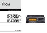
1
PFM6, PFM6BD and PFM8
Portable Hydraulic Testers
Installation & Operating Instructions
8635 Washington Avenue ■ Racine, WI 53406
Tel: 800-433-5263 or 262-639-6770
Fax: 800-245-3569 or 262-639-2267
E-Mail: [email protected]
www.flo-tech.com
Portable Hydraulic Testers
Installation & Operating Instructions
Table of Contents
Introduction ......................................................................................................................................................................4
Specifications
Material .....................................................................................................................................................................5
Performance .............................................................................................................................................................5
Calibration .................................................................................................................................................................6
Model Number Designations .....................................................................................................................................6
Dimensions ...............................................................................................................................................................7
Installation .......................................................................................................................................................................8
Operation .........................................................................................................................................................................8
Test Procedures
Standard Test Conditions ........................................................................................................................................10
Pump Test ............................................................................................................................................................... 11
"Tee" Test ................................................................................................................................................................ 11
Control Valve, Cylinder and Hydraulic Motor Test ...................................................................................................12
Relief Valve in Separate Housing............................................................................................................................13
Relief Valves ...........................................................................................................................................................13
Maintenance / Troubleshooting
Load Valve ..............................................................................................................................................................14
Flow ........................................................................................................................................................................14
Burst Discs ..............................................................................................................................................................14
Battery Replacement ..............................................................................................................................................17
Flow vs Pressure Drop Charts.......................................................................................................................................18
Hydraulic Formulas and Viscosity Information ....................................................................................................................19
Return Goods Authorization ..........................................................................................................................................20
Waste and Electronic Equipment (WEEE) Directive .....................................................................................................20
Warranty ........................................................................................................................................................................21
Form #FLIT 565 08/10
Page 3
Portable Hydraulic Testers
Installation & Operating Instructions
Introduction
Flo-tech Portable Hydraulic Testers are designed to provide fast diagnostic troubleshooting of hydraulic systems and
components. These compact, self-contained testers feature laboratory accuracy and provide flow, temperature, pressure
and optional power measurements simultaneously from one point.
Flo-tech offers three models, all available in a choice of up to 5 flow ranges and 3 port sizes:
PFM6 Digital Hydraulic Tester
Features:
•
•
•
•
•
•
•
Accuracy of ±1% of full flow range
3-1/2 digit LCD display for flow and temperature
Helical tube pressure gauge
One toggle switch to control power and select flow and temperature
Loading valve with fingertip control of pressure up to 6000 PSI (414 Bar)
Platinum resistive temperature sensor
Internal over pressure burst disc protection
PFM6BD Bi-directional Hydraulic Tester
Features:
•
•
•
•
•
•
•
•
•
Bi-directional testing
Low pressure drop
Accuracy of ±1% of full flow range
3-1/2 digit LCD display for flow and temperature
Helical tube pressure gauge
One toggle switch to control power and select flow and temperature
Loading valve with fingertip control of pressure up to 6000 PSI (414 Bar)
Platinum resistive temperature sensor
Internal over pressure burst disc protection
PFM8 Digital Hydraulic Tester & Dynamometer
Features:
•
•
•
•
•
•
•
•
Page 4
Accuracy of ±1% of full flow range
3-1/2 digit LCD displays
Digital pressure readings
Membrane switch to select flow, temperature, pressure or power
Front panel switch to select U.S. or metric readings
Loading valve with fingertip control of pressure up to 6000 PSI (414 Bar)
Platinum resistive temperature sensor
Internal over pressure burst disc protection
Form #FLIT 565 08/10
Portable Hydraulic Testers
Installation & Operating Instructions
Specifications
Material
Housing:
Turbine Rotor:
Rotor Supports:
Seals:
Ball Bearings:
Hub Cones:
Temperature Probe:
PFM6/8 Series Testers
Valve
for 15/30 Models:
for 60/85/200 Models:
Sleeve for 200 Model:
Poppet:
Straightening Sections
for 15/30 Models:
for 60/85/200 Models:
Cones:
PFM6BD Series Testers
Valve:
Spool/Sleeve:
Straightening Sections:
Cones:
Ports:
Magnetic Pick-up
Body:
Nut:
Electronic Case & Cover:
6013-T351 Anodized aluminum
T416 Stainless steel
6061-T6 Aluminum
Buna N standard
Viton® and EPR optional
440 C Stainless steel
6061-T6 Aluminum alloy
12L14 Steel, electroless nickel plate
Cold rolled steel body with 303 SS stem
12L14 steel body with 303 SS stem
D.O.M. steel tube
12L14 Steel, hardened
CA360 Brass
6061-T6 Aluminum
2024-T4 Aluminum
12L14 steel body with 303 SS stem
4340 Alloy steel, hardened
6061-T6 Aluminum
2024-T4 Aluminum
SAE Straight thread O-ring boss, female, J1926/1;
BSPP ISO1179
12L14 steel, electroless nickel plate
12L14 steel, electroless nickel plate
Cold rolled steel, zinc plate with
clear seal, epoxy black paint
Performance
Flow Accuracy:
Repeatability:
Pressure Rating:
Turbine Response:
Fluid Temperature:
Ambient Temperature:
Flow Readout:
Operating Pressure:
Pressure Drop:
Fluid Temperature:
Readout Accuracy:
Battery Type:
Form #FLIT 565 08/10
±1% of full scale
±0.2%
6000 PSI (414 Bar) maximum with a 3:1 safety factor
≤200 ms
-4 to +300 °F (-20 to +150 °C)
-4 to +131 °F (-20 to +55 °C)
Linearity and zero shift = ±1 digit
up to 6000 PSI (414 Bar, 41.4 MPa, 420 kg/cm2)
See ∆ P charts on page 18
up to 300 °F (150 °C)
±1 digit
AA size alkaline, ~50 hrs of service
Page 5
Portable Hydraulic Testers
Installation & Operating Instructions
Calibration
Testers are calibrated with a 32 cSt (150 SUS) hydraulic oil. Standard calibration is done using 5 points and is
traceable to NIST, ISO 9001. An optional 10 point calibration can be performed for increased accuracy.
Series/Model Number Designations
SERIES
MODEL
NUMBER *
NOMINAL
PORT SIZE
FLOW
RATE
POWER
HP (kW)
PFM6-15
F5080 (CE) - XXX
SAE 12
1 - 15 GPM
PFM6-30
F5079 (CE) - XXX
SAE 12
2 - 30 GPM
PFM6-60
F5078 (CE) - XXX
SAE 16
3 - 60 GPM
PFM6-85
F5077 (CE) - XXX
SAE 16
4 - 85 GPM
PFM6-200
F5076 (CE) - XXX
SAE 24
7 - 199.9 GPM
PFM6-15
F5110 (CE) - XXX
G 3/4
4 - 56 LPM
PFM6-30
F5111 (CE) - XXX
G 3/4
7.5 - 113.6 LPM
PFM6-60
F5112 (CE) - XXX
G1
12 - 227 LPM
PFM6-85
F5113 (CE) - XXX
G1
15 - 321 LPM
PFM6-200
F5114 (CE) - XXX
G 1-1/2
26 - 757 LPM
PFM6BD-60
F5082 (CE) - XXX
SAE 16
3 - 60 GPM / 12 - 227 LPM
PFM6BD-85
F5083 (CE) - XXX
SAE 16
4 - 85 GPM / 15 - 321 LPM
PFM6BD-200
F5084 (CE) - XXX
SAE 24
7 - 199.9 GPM / 26 - 757 LPM
PFM8-15
F5061
SAE 12
1 - 15 GPM / 4 - 56 LPM
52.5 (39)
PFM8-30
F5058
SAE 12
2 - 30 GPM / 7.5 - 113.6 LPM
105 (78)
PFM8-60
F5052
SAE 16
3 - 60 GPM / 12 - 227 LPM
210 (157)
PFM8-85
F5053
SAE 16
4 - 85 GPM / 15 - 321 LPM
298 (222)
PFM8-200
F5054
SAE 24
7 - 199.9 GPM / 26 - 757 LPM
700 (522)
* Replace XXX with PSI, BAR, KG/CM2 or MPA to specify complete model number.
Page 6
Form #FLIT 565 08/10
Portable Hydraulic Testers
Installation & Operating Instructions
Dimensions
SERIES
DIMENSIONS Length (A) × Depth (B) × Height (C)
INCHES
mm
WEIGHT
LBS (KG)
PFM6-15
11.3 × 3.5 × 9.8
287 × 89 × 249
13.85 (6.3)
PFM6-30
11.3 × 3.5 × 9.8
287 × 89 × 249
13.85 (6.3)
PFM6-60
11.5 × 3.5 × 9.8
292 × 89 × 249
16.50 (7.5)
PFM6-85
11.5 × 3.5 × 9.8
292 × 89 × 249
16.50 (7.5)
PFM6-200
12.3 × 4.0 × 10.3
311 × 101 × 262
20.00 (9.1)
PFM6BD-60
11.3 × 3.5 × 10.1
287 × 89 × 256
16.50 (7.5)
PFM6BD-85
11.3 × 3.5 × 10.1
287 × 89 × 256
16.50 (7.5)
PFM6BD-200
11.8 × 4.0 × 10.6
300 × 101 × 268
20.00 (9.1)
PFM8-15
11.3 × 3.5 × 9.8
287 × 89 × 249
13.85 (6.3)
PFM8-30
11.3 × 3.5 × 9.8
287 × 89 × 249
13.85 (6.3)
PFM8-60
11.5 × 3.5 × 9.8
292 × 89 × 249
16.50 (7.5)
PFM8-85
11.5 × 3.5 × 9.8
292 × 89 × 249
16.50 (7.5)
PFM8-200
12.3 × 4.0 × 10.3
311 × 101 × 262
20.00 (9.1)
2
1
C1 - PFM6 and PFM8 Series
C2 - PFM6BD Series
FIGURE 1 - Hydraulic Tester Dimension Illustration
Form #FLIT 565 08/10
Page 7
Portable Hydraulic Testers
Installation & Operating Instructions
CAUTION
Read instructions thoroughly before installing the tester. If you have any questions regarding product installation or
maintenance, call your local supplier or the factory for more information.
INSTALLATION
CAUTION
The information in this manual is for general application only. Any guidelines furnished by the manufacturer of the
machine’s hydraulic components should be followed. Specific systems may require specific test procedures.
Install the PFM6, PFM6BD or PFM8 tester at any location in the hydraulic circuit with the flow from “IN” to “OUT” as
marked near the ports of the flow meter. The “IN” and “OUT” ports on the PFM6BD indicate the primary flow direction.
It is advisable to keep any elbows, tees, valves, etc. at least 12 inches (31 cm) away from the inlet and outlet ports to
preserve the accuracy of the flow measurement. Use quick disconnect couplings for easy connections and to keep
tester sealed and clean when not in use.
Diagrams illustrating Typical Test Placements for the testers are located in the Test Procedures section beginning on
page 10.
OPERATION
WARNING
All testers are shipped with the loading valve in the closed position. The loading valve must be opened fully before
initiating flow and testing of the hydraulic circuit. Turn the loading valve handle counterclockwise to the fully open
position. Failure to open the loading valve fully can result in injury to personnel and/or damage to the equipment.
The PFM6 and PFM6BD testers utilize a 3 position, single toggle switch to turn on the power and to select to display
either flow or temperature readings. These models are factory calibrated for either U.S. or metric readings.
FIGURE 2 - PFM6 and PFM6BD Toggle Switch
The PFM8 testers can be changed in the field between U.S. and metric readings via a slide switch located in the center
of the front panel. Use a small pointed object to slide this switch to the desired position. See Figure 3 on page 9.
After the selecting U.S. or metric, power and display options are made via the membrane switches. When the “ON”
switch is pressed, pressure will show in the left display and flow in the right display. To view temperature in the right LCD,
simply press the “TEMP.” switch. To view Power in the left LCD, press the “PWR.” switch.
Page 8
Form #FLIT 565 08/10
Portable Hydraulic Testers
Installation & Operating Instructions
®
FIGURE 3 - PFM8 Slide and Membrane Switches
Flow is identified by the
symbol and the
the
symbol and kilowatt by a
symbol.
symbol indicates temperature. Horsepower readings will be followed by
NOTE: If no flow has been present for five minutes, the power saver circuit will automatically shut the PFM8 off.
Pressing the “ON” switch will restore power.
To prolong battery life on all testers, select the “OFF” option by returning the toggle switch to the “OFF” position on the
PFM6 and PFM6BD models or pressing “OFF” on the membrane switch of the PFM8 model when the tester is not being
used.
Once the tester has been installed, the pressure can be regulated by operation of the loading valve.
ALWAYS START WITH THE LOADING VALVE OPEN
WARNING
Turn the loading valve handle counterclockwise to open before starting machinery. Injury to personnel and/or damage
to the equipment can result if the loading valve is fully closed.
CAUTION
The PFM6BD is not designed for high pressure "deadhead" (loading valve fully closed) applications, in the reverse
direction. Usage under this condition could lead to loading valve failure. Under such conditions, maximum operating
pressure is limited to 2000 PSI (138 Bar).
The PFM6 and PFM8 testers are equipped with a poppet style loading valve. The PFM6BD testers utilize a spool design
loading valve to accommodate bi-directional flow. The spool design requires more turns to go from total open to total
close.
Form #FLIT 565 08/10
Page 9
Portable Hydraulic Testers
Installation & Operating Instructions
Pressure is displayed as follows:
PFM6
- the gauge indicates pressure at the inlet port
PFM6BD - the gauge indicates pressure at the inlet port dependent on the direction of flow
PFM8
- pressure is displayed on the LCD. A minimum of 200 PSI (14 kg/cm2) is required to activate the display.
PSI will increment in 10s (i.e. 200, 210, 220, etc.); kg/cm2, bars or MPa will increment in single units
(i.e. 141, 142, 143, etc.)
On all models, the battery voltage is affected by cold temperatures. Allow time for the circulating oil to warm the tester
before critical measurements are taken. On the PFM6 and PFM6BD, a LO BAT signal on the display indicates a low
battery condition. On the PFM8, a flashing colon (:) on the display indicates a low battery condition. Replace the
batteries with 4 “AA” alkaline batteries. See Battery Replacement on page 17.
Test Procedures
WARNING
All testers are shipped with the loading valve in the closed position. The loading valve must be opened fully before
initiating flow and testing of the hydraulic circuit. Turn the loading valve handle counterclockwise to the fully open
position. Failure to open the loading valve fully can result in injury to personnel and/or damage to the equipment.
CAUTION
The information in this manual is for general application only. Any information furnished by the manufacturer of the
machine’s hydraulic components should be followed. Specific systems may require specific test procedures.
General Information
The PFM6 and PFM6BD testers are designed to measure flow, pressure and temperature. The PFM8 testers are
also designed to measure power.
The power measurements are derived from the product of flow and pressure. When using a PFM6 or PFM6BD,
power can be calculated using the formulas on page 19.
Standard Test Conditions
1. Install the PFM tester as described in one of the following test procedures:
a.
b.
c.
d.
e.
Pump Test
“Tee” Test
Control Valve, Cylinder and Hydraulic Motor Test
Relief Valves in Separate Housings
Relief Valves
2. Open the loading valve fully by turning the handle counterclockwise.
3. Start the pump and adjust it to rated speed.
4. To raise the system temperature, close the tester loading valve to develop a pressure somewhat below the relief
valve pressure. Maintain until the desired temperature is reached.
5. Open the tester’s loading valve fully and proceed with the required test procedure.
6. The tester will display flow, pressure, temperature and power readings.
Page 10
Form #FLIT 565 08/10
Portable Hydraulic Testers
Installation & Operating Instructions
Pump Test
A tee must be installed between the pump discharge port and the return line to the tank. Be sure the fluid path is
only through the pump, the hydraulic test unit, and back to the tank.
FIGURE 4 - Pump Test
1. Plug the line to the control valve.
2. Open the tester loading valve fully to read maximum pump flow at zero pressure.
3. Close the loading valve to increase pressure from zero pressure to rated or maximum pump pressure to
determine pump condition.
4. The pump flow at rated pressure can now be checked against the pump manufacturer’s specifications. A
decrease in flow from zero pressure to maximum pressure indicates the pump condition. A pump that delivers
a constant low flow at zero pressure and at maximum pressure suggests suction problems.
“Tee” Test
A tee must be installed between the pump and control valve and connected to the “IN” port of the PFM tester. The
“OUT” port of the tester is connected to the tank. Pumps and relief valves can be isolated from the system and
checked with the “Tee” Test.
FIGURE 5 - “Tee” Test
Form #FLIT 565 08/10
Page 11
Portable Hydraulic Testers
Installation & Operating Instructions
WARNING
Increase pressure slowly. The relief valve may now be isolated from the hydraulic circuit, and system pressures higher
than the relief valve setting can result in injury to personnel and/or damage to the equipment.
1.
Pump Test
a. Plug the line to the control valve.
b. Open the tester loading valve fully to read maximum pump flow at zero pressure.
c.
Close the loading valve to increase pressure from zero pressure to rated or maximum pump pressure to
determine pump condition.
d. The pump flow at rated pressure can now be checked against the pump manufacturer’s specifications.
A decrease in flow from zero pressure to maximum pressure indicates the pump condition. A pump that
delivers a constant low flow at zero pressure and at maximum pressure suggests suction problems.
2. Relief Valve Test (For relief valve in separate housing, see page 13)
a. Put a control valve into a power output mode with the output flow blocked, such as a cylinder at the end of
its stroke.
b. Close the tester loading valve while viewing the pressure. Pressure will increase until the relief valve opens.
Record the pressure at this point. Repeat to check the relief valve adjustment.
Control Valve, Cylinder and Hydraulic Motor Test
FIGURE 6 - Control Valve, Cylinder and Hydraulic Motor Test (PFM6BD)
Page 12
Form #FLIT 565 08/10
Portable Hydraulic Testers
Installation & Operating Instructions
1. Put one control valve in an operating position. (Only one control valve should be in an operating position at any
one time.)
2. Slowly close the tester loading valve to achieve the pressure obtained in Step 3 under Pump Test or Step 1.c.
under "Tee" Test and record the flow. Repeat for all operating positions of all control valves.
a. If all components are in good operating condition, pressure and flow measurements should be the same as
in Step 3 of the Pump Test.
b. If a decrease in flow in any control valve position is noted, leakage is indicated. See Step 3 below for the
test routine to determine which control valve is at fault.
c.
If the decrease in flow is the same with the control valve(s) in all positions, it indicates that the relief valve
is at fault. (Note: This can also indicate some other leak is present in the control valve such as a defective
casting, damaged seals, or worn valve position detents - but always check the relief valve FIRST.)
3. To locate the fault in the control valve, cylinder or motor, disconnect cylinder and plug connection.
a. Place the control valve handle in the position where greatest decrease of flow was noted.
b. Close the tester loading valve to achieve the test pressure and record the flow.
c.
If the same decrease in flow is noted as in test performed in Step 2.b. above, then the control valve is at
fault. HOWEVER, if the flow readings are now higher and comparable to the other control valves, then a
faulty cylinder or motor is indicated.
Relief Valve in Separate Housing
1. Install the tester in a "Tee" Test configuration to the line connecting the pump and relief valve. Plug any extra
outlets.
2. Close the tester loading valve and watch the pressure and flow.
a. Reconnect the control valve to the tee. Put a control valve into a power output mode with the output flow
blocked, such as a cylinder at the end of its stroke.
b. Close the tester loading valve while watching the pressure. Pressure will increase until the relief valve
opens. Record the pressure at this point. Repeat to check the relief valve adjustment.
Relief Valves
Often relief valves will start to open before they reach their full pressure flow settings. This can be noted by comparing
the pressure and flow rate readings made in Step 3 under "Tee" Test. Any great decrease in flow rate from tests made
in Step 3 under "Tee" Test indicates a faulty relief valve.
Form #FLIT 565 08/10
Page 13
Portable Hydraulic Testers
Installation & Operating Instructions
MAINTENANCE / TROUBLESHOOTING
The PFM testers are designed to give years of trouble-free service. However, if trouble is suspected, a few simple
checks can be made.
Load Valve
If the valve fails to load the system, remove the valve body and check for foreign material, worn parts or seals.
Flow
The absence of any flow reading may indicate a blockage of the turbine. Remove the retaining ring from the inlet port
and carefully remove the turbine assembly. Remove any material that may be preventing easy rotation of the rotor.
Reassemble and attempt a flow reading again. If the tester still fails to indicate flow, it is recommended to return the
tester to the factory. For return procedures, see the Return Goods Authorization section of the manual on page 20.
Burst Discs and Burst Disc Bodies
The burst discs are designed to rupture at a specified pressure. The PFM6 and PFM8 testers have a single burst disc
that by-passes flow around the loading valve when ruptured. The PFM6BD testers provide protection from excessive
pressure in either direction with two internal burst discs that when ruptured by-pass flow around the loading valve. If
rupture occurs, the burst discs must be replaced.
WARNING
If you do not have the proper tools to accomplish this task, it is highly recommended that you return the tester(s) to the
factory for replacement of the burst disc housing and the burst discs. Injury to personnel and/or damage to equipment
may result if the burst discs are installed improperly.
The following tools and parts will be needed:
• ⅝" open end box wrench
• 0-80 (or greater) pound-inch torque wrench
• Burst discs
PFM6
- P.N. F1614-7500
(1 each)
PFM6BD - P.N. F1614-7500
(2 each)
PFM8
- P.N. F1614-7500
(1 each)
• Optional
O-Ring
- P.N. F3137-015
(1 each)
Backup Ring - P.N. F1015-015
(1 each)
Page 14
Form #FLIT 565 08/10
Portable Hydraulic Testers
Installation & Operating Instructions
A. Burst Disc Procedure for PFM6 and PFM8 Testers
1. Position the tester block to expose the internal burst disc body as shown in Figure 7.
Burst Disc Body (1)
Backup Ring (1)
O-Ring (1)
Burst Disc (1)
FIGURE 7 - PFM6 and PFM8 Burst Disc
2. Loosen the burst disc body from the flow meter block.
3. Remove the burst disc body from the flow meter block.
4. Remove the ruptured burst disc from the flow meter block and discard.
5. Clean out the burst disc port. Remove any debris from the sealing surfaces.
6. Rotate the tester to face the burst disc port upwards and drop in a new burst disc. Make sure it lies flat on the sealing
surface entrance. Lubricate the O-ring on the burst disc housing and insert it back into the block. Tighten the burst
disc housing down to form the disc against the sealing surface.
7. Using a torque wrench, tighten the burst disc body in the block to 35 foot-pounds (50.8 Nm).
CAUTION
Do not over torque the burst disc housing. Applying too much torque will damage the burst disc and cause the disc
to rupture prematurely.
Form #FLIT 565 08/10
Page 15
Portable Hydraulic Testers
Installation & Operating Instructions
B. Burst Disc Procedure for PFM6BD
1. Position the PFM6BD to expose the internal burst disc body as shown in Figure 8.
Burst Disc (1of 2)
Support Ring (1)
Burst Disc (2 of 2)
O-Ring (1)
Backup Ring (1)
Burst Disc Body (1)
FIGURE 8 - PFM6BD Burst Discs
2. Loosen the burst disc body from the flow meter block.
3. Remove the burst disc body from the flow meter block.
4. Remove the ruptured burst discs from the flow meter block and discard. Retain the support ring.
5. Clean out the burst disc port and the support ring. Remove any debris from the sealing surfaces.
6. Rotate the tester to face the burst disc port upwards and drop in a new burst disc. Make sure it lies flat on the
sealing surface entrance. Drop in the support ring and follow it with the second burst disc. Lubricate the O-ring on
the burst disc housing and insert it back into the block. Tighten the burst disc housing down to form the disc against
the sealing surfaces.
7. Using a torque wrench, tighten the burst disc body in the block to 60 foot-pounds (81.4 Nm).
CAUTION
Do not over torque the burst disc housing. Applying too much torque will damage the burst disc and cause the disc
to rupture prematurely.
Page 16
Form #FLIT 565 08/10
Portable Hydraulic Testers
Installation & Operating Instructions
Battery Replacement
All PFM testers utilize four AA size alkaline batteries. These batteries will normally provide approximately 50 hours of
service before a low battery condition is indicated. On the PFM6 and PFM6BD, a LO BAT signal on the display indicates
a low battery condition. On the PFM8, a flashing colon (:) on the display indicates a low battery condition. When a low
battery condition has been displayed, immediately remove discharged batteries from the tester to prevent battery holder
corrosion.
To change the batteries, remove the 4 screws on the cover assembly. Pull the cover slowly upward to clear the internal
components. The batteries are located on the bottom of the case. See Figure 9. When installing the new batteries,
ensure that they are centered in the holder and making contact at both ends. Replace the cover and secure the 4
screws.
FIGURE 9 - Battery Replacement
Form #FLIT 565 08/10
Page 17
Portable Hydraulic Testers
Installation & Operating Instructions
Flow vs Pressure Drop Charts – ∆P Captured Using Loading Valves
PFM6 -15, PFM8 -15
50
40
30
20
0
5
10
FLOW GPM
40
30
20
0
10
20
30
40
FLOW GPM
50
60
0
10
20
FLOW GPM
30
40
PFM6 - 85, PFM8 - 85
100
80
60
40
0
70
PFM6 - 200, PFM8 - 200
0
10
20
30
40
25
20
15
10
50 60
FLOW GPM
70
80
90
100
PFM6BD - 60
120
PRESSURE DROP PSI
30
PRESSURE DROP PSI
10
20
10
100
80
FORWARD
REVERSE
60
40
20
5
0
0
20
40
60
80
0
100 120 140 160 180 200 220
FLOW GPM
PFM6BD - 85
10
20
50
40
FORWARD
REVERSE
30
20
30
40
FLOW GPM
50
60
70
PFM6BD - 200
40
PRESSURE DROP PSI
60
PRESSURE DROP PSI
15
120
50
0
20
0
20
PRESSURE DROP PSI
PRESSURE DROP PSI
15
PFM6 -60, PFM8 -60
60
0
25
5
10
0
PFM6 - 30, PFM8 - 30
30
PRESSURE DROP PSI
PRESSURE DROP PSI
60
35
30
25
FORWARD
REVERSE
20
15
10
10
0
5
0
Page 18
10
20
30
40
50
60
FLOW GPM
70
80
90
100
0
0
20
40
60
80
100 120 140 160 180 200 220
FLOW GPM
Form #FLIT 565 08/10
Portable Hydraulic Testers
Installation & Operating Instructions
Hydraulic Formulas and Viscosity Information
Flow Rate Formulas
Frequency (Hz)
=
K × GPM
60
GPM
=
Hz × 60
K
K factor (K)
=
Hz × 60
GPM
Time Base (TB)
=
GPM
Hz
Flow Rate Related Formulas
Valve Cv Factor =
Cylinder Velocity =
Flow Rate (GPM) × √Fluid Specific Gravity
√∆P across valve (PSI)
0.3208 × Flow Rate (GPM)
Net Cylinder Area (in²)
Fluid Motor Torque =
Flow Rate (GPM) × Pressure (PSIG) × 36.77
Rotational Speed
Power Calculations
H.P. =
GPM × PSI
1714
H.P. =
liters/min × Bar
447.4
kW =
liters/min × Bar
600
Fluid Viscosity Conversion Table
Fluid viscosity used to calibrate
Testers and Sensors.
±1% Viscosity Range for Flo-tech Testers
and Sensors is 25 to 500 SUS
►
►
►
Saybolt Universal
Seconds (SUS)
ISO-VG
CentiStoke
CentiPoise ¹
Typical Brands/Liquids at 100 °F
31
2
1.0
0.876
Water
35
3
2.5
2.19
-
40
5
4.2
3.68
-
45
5/7
5.9
5.17
-
50
7
7.5
6.57
Kerosene
55
7/10
8.8
7.71
Atlantic Richfield/Duro 55 Hydraulic Oil
60
10
10.5
9.20
Monsanto/Skydrol - 500 A
70
10/15
13.2
11.56
Mobil/Aero HFA Hydraulic Oil
80
15
15.7
13.75
No. 4 Fuel Oil
90
22
18.2
15.94
Stauffer Chemical/Fyrquel 90
100
22
20.6
18.05
Conoco/Syncon Synthetic AW Hydraulic Oil
150
32
32.0
28.03
Mobil/DTE 24 Hydraulic Oil
200
46
43.2
37.84
Citco/Glycol FR-40XD (Oil in Water)
300
68
65.0
56.94
SAE 20 Crankcase Oil
400
68/100
86.0
75.34
Sunoco/Sunvis 41 Hydraulic Oil
500
100
108
94.61
SAE 30 Crankcase Oil
750
150
162
141.91
SAE 40 Crankcase Oil
1000
220
216
189.22
Mobil/Paper Machine Oil - Type K
1500
320
323
282.95
SAE 50 Crankcase Oil
2000
460
431
377.56
Amoco/American Industrial Oil - No. 460
3000
680
648
567.65
SAE 140 Gear Oil
4000
1000
862
755.11
SAE 250 Gear Oil
¹ CentiPoise are given for oil of 0.876 specific gravity. Relationship: CentiStokes × Specific Gravity = CentiPoise
Form #FLIT 565 08/10
Page 19
Portable Hydraulic Testers
Installation & Operating Instructions
Return Goods Authorization
When returning equipment for service, a Returned Goods Authorization (RGA) number must be obtained
from our Service Department. Please contact them by phone at 800-433-5263 or 262-639-6770 or by e-mail
to [email protected].
All returns go to the following address and must include the RGA number on the outside of the box:
Flo-tech
Division of Racine Federated Inc.
8635 Washington Avenue
Racine, WI 53406-3738 USA
Attn: RGA # xxx-xxxx
Waste and Electronic Equipment (WEEE) Directive
In the European Union, this label indicates that this product should not be disposed of with household
waste. It should be deposited at an appropriate facility to enable recovery and recycling.
For information on how to recycle this product responsibly in your country, please visit:
www.racinefed.com/recycle/
Page 20
Form #FLIT 565 08/10
Portable Hydraulic Testers
Installation & Operating Instructions
Flo-tech
Division of Racine Federated Inc.
Limited Warranty and Disclaimer
Flo-tech, Division of Racine Federated Inc. warrants to the end purchaser, for a period of one year from
the date of shipment from the factory, that all flow meters manufactured by it are free from defects in
materials and workmanship. This warranty does not cover products that have been damaged due to
misapplication, abuse, lack of maintenance, or improper installation. Flo-tech’s obligation under this
warranty is limited to the repair or replacement of a defective product, at no charge to the end purchaser,
if the product is inspected by Flo-tech and found to be defective. Repair or replacement is at Flo-tech’s
discretion. A returned goods authorization (RGA) number must be obtained from Flo-tech before any
product may be returned for warranty repair or replacement. The product must be thoroughly cleaned
and any process chemicals removed before it will be accepted for return.
The purchaser must determine the applicability of the product for its desired use and assumes all risks
in connection therewith. Flo-tech assumes no responsibility or liability for any omissions or errors in
connection with the use of its products. Flo-tech will under no circumstances be liable for any incidental,
consequential, contingent or special damages or loss to any person or property arising out of the failure
of any product, component or accessory.
All expressed or implied warranties, including the implied warranty of merchantability and the
implied warranty of fitness for a particular purpose or application are expressly disclaimed and
shall not apply to any products sold or services rendered by Flo-tech.
The above warranty supersedes and is in lieu of all other warranties, either expressed or implied and
all other obligations or liabilities. No agent or representative has any authority to alter the terms of this
warranty in any way.
Form #FLIT 565 08/10
Page 21
Portable Hydraulic Testers
Installation & Operating Instructions
NOTES
Page 22
Form #FLIT 565 08/10
8635 Washington Avenue ▪ Racine, WI 53406-3738
flo-tech.com
Tel: 800-433-5263 or 262-639-6770
Fax: 800-245-3569 or 262-639-2267
E-Mail: [email protected]
Materials and specifications subject to change without notice.
FLO-CHECK is a registered trademark of Racine Federated Inc.
Flo-tech is a trademark of Racine Federated Inc.
VITON is a registered trademark of DuPont Dow Elastomers.
UL is a registered trademark of Underwriters Laboratories.
© 2010 Racine Federated Inc.
All rights reserved.
Printed in USA
Form #FLIT 565 08/10