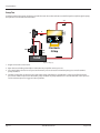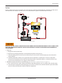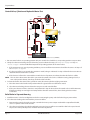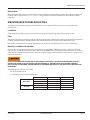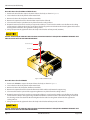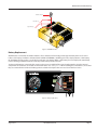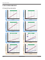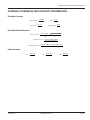
1
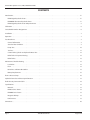
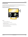
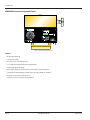
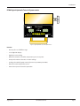
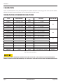
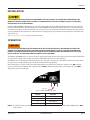
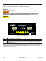
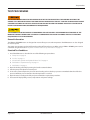
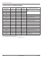
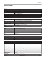
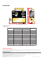
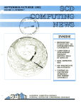
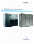
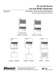
PFM Portable Hydraulic Testers
PFM6, PFM6BD and PFM8
TUR-UM-00730-EN-02 (August 2014)
User Manual
PFM Portable Hydraulic Testers, PFM6, PFM6BD and PFM8
CONTENTS
Introduction . . . . . . . . . . . . . . . . . . . . . . . . . . . . . . . . . . . . . . . . . . . . . . . . . . . . . . . . . . . . . . . . . . . . . . . . . iii
PFM6 Digital Hydraulic Tester . . . . . . . . . . . . . . . . . . . . . . . . . . . . . . . . . . . . . . . . . . . . . . . . . . . . . . . . . . . iii
PFM6BD Bi-directional Hydraulic Tester . . . . . . . . . . . . . . . . . . . . . . . . . . . . . . . . . . . . . . . . . . . . . . . . . . . . iv
PFM8 Digital Hydraulic Tester & Dynamometer . . . . . . . . . . . . . . . . . . . . . . . . . . . . . . . . . . . . . . . . . . . . . . . . 5
Calibration . . . . . . . . . . . . . . . . . . . . . . . . . . . . . . . . . . . . . . . . . . . . . . . . . . . . . . . . . . . . . . . . . . . . . . . . . . 6
Series/Model Number Designations . . . . . . . . . . . . . . . . . . . . . . . . . . . . . . . . . . . . . . . . . . . . . . . . . . . . . . . . . .6
Installation . . . . . . . . . . . . . . . . . . . . . . . . . . . . . . . . . . . . . . . . . . . . . . . . . . . . . . . . . . . . . . . . . . . . . . . . . . 7
Operation . . . . . . . . . . . . . . . . . . . . . . . . . . . . . . . . . . . . . . . . . . . . . . . . . . . . . . . . . . . . . . . . . . . . . . . . . . .7
Test Procedures . . . . . . . . . . . . . . . . . . . . . . . . . . . . . . . . . . . . . . . . . . . . . . . . . . . . . . . . . . . . . . . . . . . . . . . 9
General Information . . . . . . . . . . . . . . . . . . . . . . . . . . . . . . . . . . . . . . . . . . . . . . . . . . . . . . . . . . . . . . . . . 9
Standard Test Conditions . . . . . . . . . . . . . . . . . . . . . . . . . . . . . . . . . . . . . . . . . . . . . . . . . . . . . . . . . . . . . . 9
Pump Test . . . . . . . . . . . . . . . . . . . . . . . . . . . . . . . . . . . . . . . . . . . . . . . . . . . . . . . . . . . . . . . . . . . . . . . 10
Tee Test . . . . . . . . . . . . . . . . . . . . . . . . . . . . . . . . . . . . . . . . . . . . . . . . . . . . . . . . . . . . . . . . . . . . . . . . 11
Control Valve, Cylinder and Hydraulic Motor Test . . . . . . . . . . . . . . . . . . . . . . . . . . . . . . . . . . . . . . . . . . . . . . 12
Relief Valve in Separate Housing . . . . . . . . . . . . . . . . . . . . . . . . . . . . . . . . . . . . . . . . . . . . . . . . . . . . . . . . . 12
Relief Valves . . . . . . . . . . . . . . . . . . . . . . . . . . . . . . . . . . . . . . . . . . . . . . . . . . . . . . . . . . . . . . . . . . . . . . 13
Maintenance/Troubleshooting . . . . . . . . . . . . . . . . . . . . . . . . . . . . . . . . . . . . . . . . . . . . . . . . . . . . . . . . . . . . 13
Load Valve . . . . . . . . . . . . . . . . . . . . . . . . . . . . . . . . . . . . . . . . . . . . . . . . . . . . . . . . . . . . . . . . . . . . . . . 13
Flow . . . . . . . . . . . . . . . . . . . . . . . . . . . . . . . . . . . . . . . . . . . . . . . . . . . . . . . . . . . . . . . . . . . . . . . . . . . 13
Burst Discs and Burst Disc Bodies . . . . . . . . . . . . . . . . . . . . . . . . . . . . . . . . . . . . . . . . . . . . . . . . . . . . . . . . 13
Battery Replacement . . . . . . . . . . . . . . . . . . . . . . . . . . . . . . . . . . . . . . . . . . . . . . . . . . . . . . . . . . . . . . . . 15
Flow vs Pressure Drop . . . . . . . . . . . . . . . . . . . . . . . . . . . . . . . . . . . . . . . . . . . . . . . . . . . . . . . . . . . . . . . . . . 16
Hydraulic Formulas and Viscosity Information . . . . . . . . . . . . . . . . . . . . . . . . . . . . . . . . . . . . . . . . . . . . . . . . . . . 17
Fluid Viscosity Conversion Table . . . . . . . . . . . . . . . . . . . . . . . . . . . . . . . . . . . . . . . . . . . . . . . . . . . . . . . . . . . . 18
Specifications . . . . . . . . . . . . . . . . . . . . . . . . . . . . . . . . . . . . . . . . . . . . . . . . . . . . . . . . . . . . . . . . . . . . . . . 19
Material . . . . . . . . . . . . . . . . . . . . . . . . . . . . . . . . . . . . . . . . . . . . . . . . . . . . . . . . . . . . . . . . . . . . . . . . 19
PFM6/8 Series Testers . . . . . . . . . . . . . . . . . . . . . . . . . . . . . . . . . . . . . . . . . . . . . . . . . . . . . . . . . . . . . . . . 19
PFM6BD Series Testers . . . . . . . . . . . . . . . . . . . . . . . . . . . . . . . . . . . . . . . . . . . . . . . . . . . . . . . . . . . . . . . 19
Magnetic Pick-Up . . . . . . . . . . . . . . . . . . . . . . . . . . . . . . . . . . . . . . . . . . . . . . . . . . . . . . . . . . . . . . . . . . 19
Performance . . . . . . . . . . . . . . . . . . . . . . . . . . . . . . . . . . . . . . . . . . . . . . . . . . . . . . . . . . . . . . . . . . . . . 19
Dimensions . . . . . . . . . . . . . . . . . . . . . . . . . . . . . . . . . . . . . . . . . . . . . . . . . . . . . . . . . . . . . . . . . . . . . . . . . 20
Page ii
TUR-UM-00730-EN-02
August 2014
User Manual
INTRODUCTION
Flo-tech Portable Hydraulic Testers are designed to provide fast diagnostic troubleshooting of hydraulic systems and
components. These compact, self-contained testers feature laboratory accuracy and provide flow, temperature, pressure and
optional power measurements simultaneously from one point.
Flo-tech offers three models, all available in up to five flow ranges and three port sizes.
PFM6 Digital Hydraulic Tester
Figure 1: Digital hydraulic tester
Features
• Accuracy of ±1% of full flow range
• 3-1/2 digit LCD display for flow and temperature
• Helical tube pressure gauge
• One toggle switch to control power and select flow and temperature
• Loading valve with fingertip control of pressure up to 6000 psi (414 Bar)
• Platinum resistive temperature sensor
• Internal over-pressure burst disc protection
August 2014
TUR-UM-00730-EN-02
Page iii
Introduction
PFM6BD Bi-directional Hydraulic Tester
Figure 2: Bi-directional hydraulic tester
Features
• Bi-directional testing
• Low pressure drop
• Accuracy of ±1% of full flow range
• 3-1/2 digit LCD display for flow and temperature
• Helical tube pressure gauge
• One toggle switch to control power and select flow and temperature
• Loading valve with fingertip control of pressure up to 6000 psi (414 Bar)
• Platinum resistive temperature sensor
• Internal over-pressure burst disc protection
Page 4
TUR-UM-00730-EN-02
August 2014
Introduction
PFM8 Digital Hydraulic Tester & Dynamometer
Flo-check
TM
U.S.
PRESSURE
METRIC
LOW -
EMP
PFM
GPM, l/min - F°, C°
- H.P., - kW
PWR
OPEN LOAD VALVE BEFORE
OPERATING
DO NOT STAND IN FRONT OF
PRESSURE RELIEF DISC VENT
PRESS
ON
OFF
LOW
EMP
AUTO SHUT-OFF 5 MINUTES
WHEN NO FLOW
FLASHING LO-BAT?
REPLACE BATTERIES.
INDICATES DISPLAY
OVER RANGE.
Figure 3: Digital hydraulic tester and dynamometer
Features
• Accuracy of ±1% of full flow range
• 3-1/2 digit LCD displays
• Digital pressure readings
• Membrane switch to select flow, temperature, pressure or power
• Front panel switch to select U.S. or metric readings
• Loading valve with fingertip control of pressure up to 6000 psi (414 Bar)
• Platinum resistive temperature sensor
• Internal over-pressure burst disc protection
August 2014
TUR-UM-00730-EN-02
Page 5
Calibration
CALIBRATION
Testers are calibrated with a 32 cSt (150 SUS) hydraulic oil. Standard calibration is done using 5 points and is traceable to NIST,
ISO 9001. An optional 10 point calibration can be performed for increased accuracy.
SERIES/MODEL NUMBER DESIGNATIONS
Series
Model Number *
Nominal Port
Size
Flow Rate
PFM6-15
F5080 (CE) - XXX
SAE 12
1…15 GPM
PFM6-30
F5079 (CE) - XXX
SAE 12
2…30 GPM
PFM6-60
F5078 (CE) - XXX
SAE 16
3…60 GPM
PFM6-85
F5077 (CE) - XXX
SAE 16
4…85 GPM
PFM6-200
F5076 (CE) - XXX
SAE 24
7…199.9 GPM
PFM6-15
F5110 (CE) - XXX
G 3/4
4…56 LPM
PFM6-30
F5111 (CE) - XXX
G 3/4
7.5…113.6 LPM
PFM6-60
F5112 (CE) - XXX
G1
12…227 LPM
PFM6-85
F5113 (CE) - XXX
G1
15…321 LPM
PFM6-200
F5114 (CE) - XXX
G 1-1/2
26…757 LPM
PFM6BD-60
F5082 (CE) - XXX
SAE 16
3…60 GPM / 12…227 LPM
PFM6BD-85
F5083 (CE) - XXX
SAE 16
4…85 GPM / 15…321 LPM
PFM6BD-200
F5084 (CE) - XXX
SAE 24
7…199.9 GPM / 26…757 LPM
PFM8-15
F5061
SAE 12
1…15 GPM / 4…56 LPM
52.5 (39)
PFM8-30
F5058
SAE 12
2…30 GPM / 7.5…113.6 LPM
105 (78)
PFM8-60
F5052
SAE 16
3…60 GPM / 12…227 LPM
210 (157)
PFM8-85
F5053
SAE 16
4…85 GPM / 15…321 LPM
98 (222)
PFM8-200
F5054
SAE 24
7…199.9 GPM / 26…757 LPM
700 (522)
Power HP (kW)
N/A
N/A
N/A
* Replace XXX with Psi, BAR, KG/CM2 or MPA to specify complete model number.
Table 1: Model number designations
READ INSTRUCTIONS THOROUGHLY BEFORE INSTALLING THE TESTER. IF YOU HAVE ANY QUESTIONS REGARDING
PRODUCT INSTALLATION OR MAINTENANCE, CALL YOUR LOCAL SUPPLIER OR THE FACTORY FOR MORE INFORMATION.
Page 6
TUR-UM-00730-EN-02
August 2014
Installation
INSTALLATION
THE INFORMATION IN THIS MANUAL IS FOR GENERAL APPLICATION ONLY. ANY GUIDELINES FURNISHED BY THE
MANUFACTURER OF THE MACHINE’S HYDRAULIC COMPONENTS SHOULD BE FOLLOWED. SPECIFIC SYSTEMS MAY
REQUIRE SPECIFIC TEST PROCEDURES.
Install the PFM6, PFM6BD or PFM8 tester at any location in the hydraulic circuit with the flow from IN to OUT as marked near
the ports of the flow meter. The IN and OUT ports on the PFM6BD indicate the primary flow direction. It is advisable to keep
any elbows, tees, valves, or other obstructions, at least 12 inches (31 cm) away from the inlet and outlet ports to preserve the
accuracy of the flow measurement. Use quick disconnect couplings for easy connections and to keep tester sealed and clean
when not in use.
See "Test Procedures" on page 9 for typical test placement.
OPERATION
ALL TESTERS ARE SHIPPED WITH THE LOADING VALVE IN THE CLOSED POSITION. THE LOADING VALVE MUST BE
OPENED FULLY BEFORE INITIATING FLOW AND TESTING OF THE HYDRAULIC CIRCUIT. TURN THE LOADING VALVE
HANDLE COUNTERCLOCKWISE TO THE FULLY OPEN POSITION. FAILURE TO OPEN THE LOADING VALVE FULLY CAN
RESULT IN INJURY TO PERSONNEL AND/OR DAMAGE TO THE EQUIPMENT.
The PFM6 and PFM6BD testers use a three position, single toggle switch to turn on the power and select to display either flow
or temperature readings. These models are factory calibrated for either U.S. or metric readings.
The PFM8 testers can be changed in the field between U.S. and metric readings via a slide switch located in the center of the
front panel. Use a small pointed object to slide this switch to the desired position.
After selecting U.S. or metric, select power and display options are made via the membrane switches. Press ON to display
pressure on the left side and flow on the right side. Press TEMP to display the temperature on the right side. Press PWR to
display the power on the left side.
Toggle Switch
Figure 4: PFM6 and PFM6BD toggle switch
Display
Function
F
Flow
T (stylized)
Temperature
H
Horsepower
P
Kilowatt
NNOTE: If no flow has been present for five minutes, the power saver circuit will automatically shut the PFM8 off. Press ON to
restore power.
August 2014
TUR-UM-00730-EN-02
Page 7
Operation
To prolong battery life on all testers, turn off the tester when the tester is not being used. Either return the toggle switch to
the OFF position on the PFM6 and PFM6BD models, or press OFF on the PFM8 model.
Once the tester has been installed, the pressure can be regulated by operation of the loading valve.
IIMPORTAN
Always start with the loading valve open.
TURN THE LOADING VALVE HANDLE COUNTERCLOCKWISE TO OPEN BEFORE STARTING MACHINERY. INJURY TO
PERSONNEL AND/OR DAMAGE TO THE EQUIPMENT CAN RESULT IF THE LOADING VALVE IS FULLY CLOSED.
THE PFM6BD IS NOT DESIGNED FOR HIGH PRESSURE “DEADHEAD” (LOADING VALVE FULLY CLOSED) APPLICATIONS
IN THE REVERSE DIRECTION. USAGE UNDER THIS CONDITION COULD LEAD TO LOADING VALVE FAILURE. UNDER SUCH
CONDITIONS, MAXIMUM OPERATING PRESSURE IS LIMITED TO 2000 PSI (138 BAR).
The PFM6 and PFM8 testers are equipped with a poppet style loading valve. The PFM6BD testers use a spool design loading
valve to accommodate bi-directional flow. The spool design requires more turns to go from total open to total close.
Flo-check
TM
U.S.
PRESSURE
METRIC
LOW -
EMP
PFM
GPM, l/min - F°, C°
- H.P., - kW
PWR
OPEN LOAD VALVE BEFORE
OPERATING
DO NOT STAND IN FRONT OF
PRESSURE RELIEF DISC VENT
PRESS
ON
OFF
LOW
EMP
AUTO SHUT-OFF 5 MINUTES
WHEN NO FLOW
FLASHING LO-BAT?
REPLACE BATTERIES.
INDICATES DISPLAY
OVER RANGE.
Figure 5: PFM8 slide and membrane switches
Pressure is displayed as follows:
PFM6
The gauge indicates pressure at the inlet port
PFM6BD
The gauge indicates pressure at the inlet port dependent on the direction of flow
PFM8
The pressure is displayed on the LCD. A minimum of 200 psi (14 kg/cm2) is required to activate the display. The
psi will increment in 10s (for example 200, 210, 220); kg/cm2, bars or MPA will increment in single units (for
example 141, 142, 143, etc.)
On all models, the battery voltage is affected by cold temperatures. Allow time for the circulating oil to warm the tester before
critical measurements are taken. On the PFM6 and PFM6BD, a LO BAT signal on the display indicates a low battery condition.
On the PFM8, a flashing colon on the display indicates a low battery condition. Replace the batteries with four AA alkaline
batteries. See "Battery Replacement" on page 15.
Page 8
TUR-UM-00730-EN-02
August 2014
Test procedures
TEST PROCEDURES
ALL TESTERS ARE SHIPPED WITH THE LOADING VALVE IN THE CLOSED POSITION. THE LOADING VALVE MUST BE
OPENED FULLY BEFORE INITIATING FLOW AND TESTING THE HYDRAULIC CIRCUIT. TURN THE LOADING VALVE HANDLE
COUNTERCLOCKWISE TO THE FULLY OPEN POSITION. FAILURE TO OPEN THE LOADING VALVE FULLY CAN RESULT IN
INJURY TO PERSONNEL AND/OR DAMAGE TO THE EQUIPMENT.
THE INFORMATION IN THIS MANUAL IS FOR GENERAL APPLICATION ONLY. ANY INFORMATION FURNISHED BY THE
MANUFACTURER OF THE MACHINE’S HYDRAULIC COMPONENTS SHOULD BE FOLLOWED. SPECIFIC SYSTEMS MAY
REQUIRE SPECIFIC TEST PROCEDURES.
General Information
The PFM6 and PFM6BD testers are designed to measure flow, pressure and temperature. The PFM8 testers are also designed
to measure power.
The power measurements are derived from the product of flow and pressure. When using a PFM6 or PFM6BD, power can be
calculated using the formulas in “Hydraulic Formulas and Viscosity Information” on page 17.
Standard Test Conditions
1. Install the PFM tester as described in one of the following test procedures:
a. “Pump Test” on page 10
b. “Tee Test” on page 11
c. “Control Valve, Cylinder and Hydraulic Motor Test” on page 12
d. “Relief Valve in Separate Housing” on page 12
e. “Relief Valves” on page 13
2. Open the loading valve fully by turning the handle counterclockwise.
3. Start the pump and adjust it to rated speed.
4. To raise the system temperature, close the tester loading valve to develop a pressure somewhat below the relief valve
pressure. Maintain pressure until the desired temperature is reached.
5. Open the tester’s loading valve fully and proceed with the required test procedure.
6. The tester will display flow, pressure, temperature and power readings.
August 2014
TUR-UM-00730-EN-02
Page 9
Test procedures
Pump Test
Install tee between the pump discharge port and the return line to the tank. Be sure the fluid path is only through the pump,
the hydraulic test unit and back to the tank.
OUT
IN
TEE
DO NOT STAND IN FRONT OF
PRESSURE RELIEF DISK VENT.
by HEDLAND
RACINE, WI. USA
INDICATES DISPLAY
OVER RANGE.
OPEN LOAD VALVE BEFORE
STARTING MACHINERY.
PUMP
RELIEF
VALVE
OFF
Flo-check
PFM
FLOW
TEMP
Flo-check
PFM
TANK
Figure 6: Pump test
1. Plug the line to the control valve.
2. Open the tester loading valve fully to read maximum pump flow at zero pressure.
3. Close the loading valve to increase pressure from zero pressure to rated or maximum pump pressure to determine
pump condition.
4. Check the pump flow at rated pressure against the pump manufacturer’s specifications. A decrease in flow from zero
pressure to maximum pressure indicates the pump condition. A pump that delivers a constant low flow at zero pressure
and at maximum pressure suggests suction problems.
Page 10
TUR-UM-00730-EN-02
August 2014
Test procedures
Tee Test
Install tee between the pump and control valve. Connect the tee to the IN port of the PFM tester. The OUT port of the tester is
connected to the tank. Pumps and relief valves can be isolated from the system and checked with the Tee Test.
OUT
OUT
CONTROL
VALVE
IN
TEE
DO NOT STAND IN FRONT OF
PRESSURE RELIEF DISK VENT.
by HEDLAND
RACINE, WI. USA
INDICATES DISPLAY
OVER RANGE.
OPEN LOAD VALVE BEFORE
STARTING MACHINERY.
PUMP
RELIEF
VALVE
OFF
Flo-check
PFM
FLOW
TEMP
Flo-check
PFM
TANK
Figure 7: Tee test
INCREASE PRESSURE SLOWLY. THE RELIEF VALVE MAY NOW BE ISOLATED FROM THE HYDRAULIC CIRCUIT, AND SYSTEM
PRESSURES HIGHER THAN THE RELIEF VALVE SETTING CAN RESULT IN INJURY TO PERSONNEL AND/OR DAMAGE TO
THE EQUIPMENT.
1. Pump Test
a. Plug the line to the control valve.
b. Open the tester loading valve fully to read maximum pump flow at zero pressure.
c. Close the loading valve to increase pressure from zero pressure to rated or maximum pump pressure to determine
pump condition.
d. Check the pump flow at rated pressure against the pump manufacturer’s specifications. A decrease in flow from
zero pressure to maximum pressure indicates the pump condition. A pump that delivers a constant low flow at zero
pressure and at maximum pressure suggests suction problems.
2. Relief Valve Test (for relief valve in separate housing, see “Relief Valve in Separate Housing” on page 12.)
a. Put a control valve into a power output mode with the output flow blocked, such as a cylinder at the end of its stroke.
b. Close the tester loading valve while viewing the pressure. Pressure will increase until the relief valve opens. Record the
pressure at this point. Repeat to check the relief valve adjustment.
August 2014
TUR-UM-00730-EN-02
Page 11
Test procedures
Control Valve, Cylinder and Hydraulic Motor Test
IN / OUT
OUT
HYDRAULIC
MOTOR
CONTROL
VALVE
TEE
DO NOT STAND IN FRONT OF
PRESSURE RELIEF DISK VENT.
by HEDLAND
RACINE, WI. USA
INDICATES DISPLAY
OVER RANGE.
OPEN LOAD VALVE BEFORE
STARTING MACHINERY.
OFF
Flo-check
PFM BD
FLOW
TEMP
Flo-check
PFM BD
PUMP
RELIEF
VALVE
TANK
Figure 8: Control valve, cylinder and hydraulic motor test (PFM6BD)
1. Put one control valve in an operating position. Only one control valve should be in an operating position at any one time.
2. Slowly close the tester loading valve to achieve the pressure obtained in step 3 of “Pump Test” on page 10 or Step 1c.
“Tee Test” on page 11 and record the flow. Repeat for all operating positions of all control valves.
a. If all components are in good operating condition, pressure and flow measurements should be the same as in Step 3 of
the “Pump Test” on page 10.
b. If a decrease in flow in any control valve position is noted, leakage is indicated. See Step 3 below for the test routine to
determine which control valve is at fault.
c. If the decrease in flow is the same with the control valve in all positions, it indicates that the relief valve is at fault.
NNOTE: This can also indicate some other leak is present in the control valve such as a defective casting, damaged seals, or
worn valve position detents, but always check the relief valve first.
3. To locate the fault in the control valve, cylinder or motor, disconnect cylinder and plug connection.
a. Place the control valve handle in the position where the greatest decrease of flow was noted.
b. Close the tester loading valve to achieve the test pressure and record the flow.
c. If the same decrease in flow is noted as in test performed in Step 2b above, then the control valve is at fault. However,
if the flow readings are now higher and comparable to the other control valves, then a faulty cylinder or motor
is indicated.
Relief Valve in Separate Housing
1. Install the tester in a Tee Test configuration to the line connecting the pump and relief valve. Plug any extra outlets.
2. Close the tester loading valve and watch the pressure and flow.
a. Reconnect the control valve to the tee. Put a control valve into a power output mode with the output flow blocked,
such as a cylinder at the end of its stroke.
b. Close the tester loading valve while watching the pressure. Pressure will increase until the relief valve opens. Record
the pressure at this point. Repeat to check the relief valve adjustment.
Page 12
TUR-UM-00730-EN-02
August 2014
Maintenance/troubleshooting
Relief Valves
Often relief valves will start to open before they reach their full pressure flow settings. Compare the pressure and flow rate
readings made in Step 3 under “Tee Test” on page 11. Any great decrease in flow rate from those tests indicates a faulty
relief valve.
MAINTENANCE/TROUBLESHOOTING
The PFM testers are designed to give years of trouble-free service. However, if there is an issue, you can make a few
simple checks.
Load Valve
If the valve fails to load the system, remove the valve body and check for foreign material, worn parts or seals.
Flow
The absence of any flow reading may indicate a blockage of the turbine. Remove the retaining ring from the inlet port and
carefully remove the turbine assembly. Remove any material that may be preventing easy rotation of the rotor.
Reassemble and attempt a flow reading again. If the tester still fails to indicate flow, return the tester to the factory.
Burst Discs and Burst Disc Bodies
The burst discs are designed to rupture at a specified pressure. The PFM6 and PFM8 testers have a single burst disc that
bypasses flow around the loading valve when ruptured. The PFM6BD testers provide protection from excessive pressure in
either direction with two internal burst discs that, when ruptured, bypass flow around the loading valve. If a rupture occurs,
replace the burst discs.
IF YOU DO NOT HAVE THE PROPER TOOLS TO ACCOMPLISH THIS TASK, IT IS HIGHLY RECOMMENDED THAT YOU
RETURN THE TESTER(S) TO THE FACTORY FOR REPLACEMENT OF THE BURST DISC HOUSING AND THE BURST
DISCS. INJURY TO PERSONNEL AND/OR DAMAGE TO EQUIPMENT MAY RESULT IF THE BURST DISCS ARE INSTALLED
IMPROPERLY.
The following tools and parts are needed:
• 5/8" open end box wrench
• 0…80 (or greater) pound-inch torque wrench
Burst discs
Optional
August 2014
Description
PFM6
PFM6BD
PFM8
O-ring
Backup ring
Part Number
F1614-7500
F1614-7500
F1614-7500
F3137-015
F1015-015
TUR-UM-00730-EN-02
Quantity
1
2
1
1
1
Page 13
Maintenance/troubleshooting
Burst Disc Procedure for PFM6 and PFM8 Testers
Position the tester block to expose the internal burst disc body as shown in Figure 10.
Loosen the burst disc body from the flow meter block.
Remove the burst disc body from the flow meter block.
Remove the ruptured burst disc from the flow meter block and discard.
Clean out the burst disc port. Remove any debris from the sealing surfaces.
Rotate the tester to face the burst disc port upwards and drop in a new burst disc. Make sure it lies flat on the sealing
surface entrance. Lubricate the O-ring on the burst disc housing and insert it back into the block. Tighten the burst disc
housing down to form the disc against the sealing surface.
7. Using a torque wrench, tighten the burst disc body in the block to 35 foot-pounds (50.8 Nm).
1.
2.
3.
4.
5.
6.
DO NOT OVER TORQUE THE BURST DISC HOUSING. APPLYING TOO MUCH TORQUE WILL DAMAGE THE BURST DISC
AND CAUSE THE DISC TO RUPTURE PREMATURELY.
Burst Disc Body (1)
Burst Disc (1)
Figure 9: PFM6 and PFM8 burst disc
Burst Disc Procedure for PFM6BD
Position the PFM6BD to expose the internal burst disc body as shown in Figure 11.
Loosen the burst disc body from the flow meter block.
Remove the burst disc body from the flow meter block.
Remove the ruptured burst discs from the flow meter block and discard. Retain the support ring.
Clean out the burst disc port and the support ring. Remove any debris from the sealing surfaces.
Rotate the tester to face the burst disc port upwards and drop in a new burst disc. Make sure it lies flat on the sealing
surface entrance. Drop in the support ring and follow it with the second burst disc. Lubricate the O-ring on the burst
disc housing and insert it back into the block. Tighten the burst disc housing down to form the disc against the
sealing surfaces.
7. Using a torque wrench, tighten the burst disc body in the block to 60 foot-pounds (81.4 Nm).
1.
2.
3.
4.
5.
6.
DO NOT OVER TORQUE THE BURST DISC HOUSING. APPLYING TOO MUCH TORQUE WILL DAMAGE THE BURST DISC
AND CAUSE THE DISC TO RUPTURE PREMATURELY.
Page 14
TUR-UM-00730-EN-02
August 2014
Maintenance/troubleshooting
Burst Disc Body (1)
Burst Disc (2)
Support Ring (1)
Figure 10: PFM6BD burst discs
Battery Replacement
All PFM testers use four AA size alkaline batteries. These batteries will normally provide approximately 50 hours of service
before a low battery condition is indicated. On the PFM6 and PFM6BD, a LO BAT signal on the display indicates a low battery.
On the PFM8, a flashing colon (:) on the display indicates a low battery. When a low battery has been displayed, immediately
remove discharged batteries from the tester to prevent battery holder corrosion.
To change the batteries, remove the four screws on the cover assembly. Pull the cover slowly upward to clear the internal
components. The batteries are located on the bottom of the case. See Figure 12. When installing the new batteries, ensure that
they are centered in the holder and making contact at both ends. Replace the cover and secure the four screws.
ALKALINE BATTERY
AA
1.5 VOLTS
CAUTION DO NOT CONNECT IMPROPERLY
CHANGE OR DISPOSE OF IN FIRE. BATTERY
MAY EXPLODE OR LEAK. MADE IN U.S.A.
ALKALINE BATTERY
AA
1.5 VOLTS
CAUTION DO NOT CONNECT IMPROPERLY
CHANGE OR DISPOSE OF IN FIRE. BATTERY
MAY EXPLODE OR LEAK. MADE IN U.S.A.
AA
1.5 VOLTS
CAUTION DO NOT CONNECT IMPROPERLY
CHANGE OR DISPOSE OF IN FIRE. BATTERY
MAY EXPLODE OR LEAK. MADE IN U.S.A.
AA
1.5 VOLTS
CAUTION DO NOT CONNECT IMPROPERLY
CHANGE OR DISPOSE OF IN FIRE. BATTERY
MAY EXPLODE OR LEAK. MADE IN U.S.A.
ALKALINE BATTERY
ALKALINE BATTERY
Figure 11: Battery replacement
August 2014
TUR-UM-00730-EN-02
Page 15
Flow vs pressure drop
FLOW VS PRESSURE DROP
ΔP Captured Using Loading Valves
60
30
PFM6-15, PFM8-15
PFM6-30, PFM8-30
25
PRESSURE DROP, PSI
PRESSURE DROP, PSI
50
40
30
20
10
0
0
5
10
15
20
15
10
5
0
20
0
10
20
FLOW, GPM
60
PFM6-85, PFM8-85
100
PRESSURE DROP, PSI
PRESSURE DROP, PSI
50
40
30
20
10
0
10
20
30
40
50
60
80
60
40
20
0
70
0
10
20
30
FLOW, GPM
PRESSURE DROP, PSI
PRESSURE DROP, PSI
70
80
90
100
20
15
10
5
0
20
40
60
80
Reverse
60
40
20
0
80 100 120 140 160 180 200 220
Forward
0
10
20
FLOW, GPM
30
40
50
60
70
FLOW, GPM
60
40
PFM6BD-85
50
PFM6BD-200
35
Forward
Forward
30
PRESSURE DROP, PSI
PRESSURE DROP, PSI
60
PFM6BD-60
100
25
40
Reverse
30
20
10
25
Reverse
20
15
10
5
0
10
20
30
40
50
60
70
80
90
100
0
FLOW, GPM
Page 16
50
120
PFM6-200, PFM8-200
0
40
FLOW, GPM
30
0
40
120
PFM6-60, PFM8-60
0
30
FLOW, GPM
0
20
40
60
80 100 120 140 160 180 200 220
FLOW, GPM
TUR-UM-00730-EN-02
August 2014
Hydraulic formulas and viscosity information
HYDRAULIC FORMULAS AND VISCOSITY INFORMATION
Flow Rate Formulas
Frequency (Hz) =
K-Factor (K) =
K x GPM
60
GPM =
Hz × 60
GPM
Hz × 60
K
Time Base (TB) =
GPM
Hz
Flow Rate Related Formulas
Valve C V Factor =
Flow Rate (GPM) × Fluid Specific Gravity
∆P Across Valve (PSI)
Cylinder Velocity =
Fluid Mortor Torque =
0.3208 x Flow Rate (GPM)
Net Cylinder Arrea (in2 )
Flow Rate (GPM) × Pressure (PSIG) × 36.77
Rotational Speed
Power Formulas
H.P. =
August 2014
LPM x Bar
447.4
H.P. =
LPM x Bar
447.4
TUR-UM-00730-EN-02
kW =
LPM x Bar
600
Page 17
Fluid viscosity conversion table
FLUID VISCOSITY CONVERSION TABLE
Saybolt Universal
Seconds (SUS)
ISO-VG
CentiStoke
CentiPoise¹
31
2
1.0
0.876
35
3
2.5
2.19
40
5
4.2
3.68
45
5/7
5.9
5.17
50
7
7.5
6.57
Kerosene
55
7/10
8.8
7.71
Atlantic Richfield/Duro 55 Hydraulic Oil
60
10
10.5
9.20
Monsanto/Skydrol - 500 A
70
10/15
13.2
11.56
Mobil/Aero HFA Hydraulic Oil
80
15
15.7
13.75
No. 4 Fuel Oil
90
22
18.2
15.94
Stauffer Chemical/Fyrquel 90
100
22
20.6
18.05
Conoco/Syncon Synthetic AW Hydraulic Oil
2
150
32
32.0
28.03
Mobil/DTE 24 Hydraulic Oil
200
46
43.2
37.84
Citco/Glycol FR-40XD (Oil in Water)
300
68
65.0
56.94
SAE 20 Crankcase Oil
400
68/100
86.0
75.34
Sunoco/Sunvis 41 Hydraulic Oil
500
100
108
94.61
SAE 30 Crankcase Oil
750
150
162
141.91
SAE 40 Crankcase Oil
1000
220
216
189.22
Mobil/Paper Machine Oil - Type K
1500
320
323
282.95
SAE 50 Crankcase Oil
2000
460
431
377.56
Amoco/American Industrial Oil - No. 460
3000
680
648
567.65
SAE 140 Gear Oil
4000
1000
862
755.11
SAE 250 Gear Oil
Typical Brands/Liquids at 100 °F
Water
—
¹ CentiPoise are given for oil of 0.876 specific gravity. Relationship: CentiStokes × Specific Gravity = CentiPoise
2
Fluid viscosity used to calibrate Testers and Sensors
* ±1% Viscosity Range for Flo-Tech Testers and Sensors is 25 to 500 SUS
Table 2: Viscosity conversion
Page 18
TUR-UM-00730-EN-02
August 2014
Specifications
SPECIFICATIONS
Material
Housing
Turbine Rotor
Rotor Supports
Seals
Ball Bearings
Hub Cones
Temperature Probe
6013-T351 Anodized aluminum
T416 Stainless steel
6061-T6 Aluminum
Buna N standard
Viton® and EPR optional
440 C Stainless steel
6061-T6 Aluminum alloy
12L14 Steel, electroless nickel plate
PFM6/8 Series Testers
Valve
Sleeve for 200 Model
Poppet
Straightening Sections
Cones
Cold rolled steel body with 303 SS stem (for 15/30 Models)
12L14 steel body with 303 SS stem (for 60/85/200 Models)
D.O.M. steel tube
12L14 steel, hardened
CA360 Brass (for 15/30 Models)
6061-T6 Aluminum (for 60/85/200 Models)
2024-T4 Aluminum
PFM6BD Series Testers
Valve
Sleeve for 200 Model
Poppet
Straightening Sections
Cones
12L14 steel body with 303 SS stem
4340 Alloy steel, hardened
6061-T6 Aluminum
2024-T4 Aluminum
SAE Straight thread O-ring boss, female, J1926/1;
BSPP ISO1179
Magnetic Pick-Up
Body
Nut
Electronic Case Cover
12L14 steel, electroless nickel plate
12L14 steel, electroless nickel plate
Cold rolled steel, zinc plate with clear seal, epoxy black paint
Performance
Flow Accuracy
Repeatability
Pressure Rating
Turbine Response
Fluid Temperature
Ambient Temperature
Flow Readout
Operating Pressure
Pressure Drop
Fluid Temperature
Readout Accuracy
Battery Type
August 2014
±1% of full scale
±0.2%
6000 Psi (414 Bar) maximum with a 3:1 safety factor
≤200 ms
–4…300 °F (–20…150 °C)
–4…131 °F (–20…55 °C)
Linearity and zero shift = ±1 digit
Up to 6000 psi (414 Bar, 41.4 MPa, 420 kg/cm2)
See “ΔP Captured Using Loading Valves” on page 16
Up to 300 °F (150 °C)
±1 digit
AA size alkaline, ~50 hr of service
TUR-UM-00730-EN-02
Page 19
DIMENSIONS
C2 C1
A
B
Figure 12: Hydraulic tester dimension illustration
C1 - PFM6 and PFM8 Series
C2 - PFM6BD Series
Series
PFM6-15
PFM6-30
PFM6-60
PFM6-85
PFM6-200
PFM6BD-60
PFM6BD-85
PFM6BD-200
PFM8-15
PFM8-30
PFM8-60
PFM8-85
PFM8-200
Dimensions Length (A) × Depth (B) × Height (C)
inches
mm
11.3 × 3.6 × 10.3
11.3 × 3.6 × 10.3
11.5 × 3.6 × 10.3
11.5 × 3.6 × 10.3
12.3 × 4.1 × 10.8
11.3 × 3.6 × 10.4
11.3 × 3.5 × 10.4
11.8 × 4.1 × 10.9
11.3 × 3.6 × 10.3
11.3 × 3.6 × 10.3
11.5 × 3.6 × 10.4
11.5 × 3.6 × 10.4
12.3 × 4.1 × 10.9
287 × 92 × 262
287 × 92 × 262
292 × 92 × 262
292 × 92 × 262
311 × 105 × 275
287 × 92 × 265
287 × 92 × 265
300 × 105 × 277
287 × 92 × 262
287 × 92 × 262
292 × 92 × 265
292 × 92 × 265
11 × 105 × 277
Weight Lb (kg)
13.85 (6.3)
13.85 (6.3)
16.50 (7.5)
16.50 (7.5)
20.00 (9.1)
16.50 (7.5)
16.50 (7.5)
20.00 (9.1)
13.85 (6.3)
13.85 (6.3)
16.50 (7.5)
16.50 (7.5)
20.00 (9.1)
Table 3: Dimensions
Control. Manage. Optimize.
Dynasonics is a registered trademark of Badger Meter, Inc. Other trademarks appearing in this document are the property of their respective entities. Due to continuous research,
product improvements and enhancements, Badger Meter reserves the right to change product or system specifications without notice, except to the extent an outstanding
contractual obligation exists. © 2014 Badger Meter, Inc. All rights reserved.
www.badgermeter.com
The Americas | Badger Meter | 4545 West Brown Deer Rd | PO Box 245036 | Milwaukee, WI 53224-9536 | 800-876-3837 | 414-355-0400
México | Badger Meter de las Americas, S.A. de C.V. | Pedro Luis Ogazón N°32 | Esq. Angelina N°24 | Colonia Guadalupe Inn | CP 01050 | México, DF | México | +52-55-5662-0882
Europe, Middle East and Africa | Badger Meter Europa GmbH | Nurtinger Str 76 | 72639 Neuffen | Germany | +49-7025-9208-0
Europe, Middle East Branch Office | Badger Meter Europe | PO Box 341442 | Dubai Silicon Oasis, Head Quarter Building, Wing C, Office #C209 | Dubai / UAE | +971-4-371 2503
Czech Republic | Badger Meter Czech Republic s.r.o. | Maříkova 2082/26 | 621 00 Brno, Czech Republic | +420-5-41420411
Slovakia | Badger Meter Slovakia s.r.o. | Racianska 109/B | 831 02 Bratislava, Slovakia | +421-2-44 63 83 01
Asia Pacific | Badger Meter | 80 Marine Parade Rd | 21-06 Parkway Parade | Singapore 449269 | +65-63464836
Legacy Document Number: 05-TUR-UM-00193-EN
China | Badger Meter | 7-1202 | 99 Hangzhong Road | Minhang District | Shanghai | China 201101 | +86-21-5763 5412