1
DC33
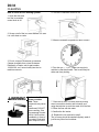
TO INSTALL: Plumbing
Built In Pump Model:
9. Flush water line. Place flare nut on inlet water
line and flare the end of the copper tube.
1. Place ice machine in front of installed location.
Adjust leg levelers to approximately correct
position.
10. Attach flare nut to the male flare on the inlet
water valve.
2. Remove kickplate and control box cover.
11. Turn on the water supply, and make sure that
the ice machine is plugged in and the power is on.
3. Route water inlet line from wall through ice
machine to the front.
12. Pour a couple of quarts of water into the
storage bin, the drain pump should start and pump
water out. Check for leaks.
4. Locate coil of plastic tubing shipped in ice
storage bin.
5. Connect tubing to discharge port of drain pump
and route drain line from back of cabinet to drain
connection point.
13. Replace kickplate and control box cover.
14. Level the cabinet left to right.
ALL PLUMBING MUST MEET LOCAL CODES
Note: Usually an air gap is required by local codes
between the ice machine drain tube and the drain
receptacle.
6. If electrical outlet for ice machine is behind the
cabinet, plug in the ice machine now.
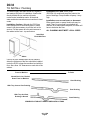
THE DC33 WILL FIT IN A SPACE
151⁄4" WIDE X 333⁄4" HIGH.
THE DEPTH OF THE CABINET IS 22" TO
THE FRONT EDGE OF THE HANDLE.
7. Push ice machine into installed position.
8. Cut off water inlet line at required length.
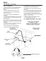
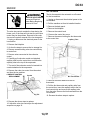
WATER AND DRAIN
INSTALLATION
Air Gap Device
(Where Required)
Drain
Connection
Drain Tube From
Back Of Machine
Water Shut Off
Valve
Water Filter
(Recommended)
Water Inlet Connection
July 1994
Page 8