1
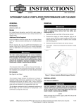
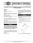
-J05717
REV. 2015-04-14
SCREAMIN' EAGLE STAGE 1 KIT FOR EFI MODELS
GENERAL
Kit Number
3.
Remove fuel tank. Refer to Section 4, FUEL SYSTEM, in
service manual.
4.
Remove and discard support induction module bracket
(B).
29400129
Models
INSTALLATION
For model fitment information, see P&A Retail Catalog or the
Parts and Accessories section of www.harley-davidson.com
(English only).
Install Air Cleaner
Additional Parts Required
Proper installation of this kit requires the use of Digital Technician™ at a Harley-Davidson dealer.
This kit requires the separate purchase of Air
Cleaner/Degreaser (99883-88T) which is available from a
Harley-Davidson dealer.
This kit requires the separate purchase of Loctite® 243 Medium
Strength Threadlocker and Sealant - Blue (Part Number 9964297)
The element in this kit is specifically designed for use with
the OE (original equipment) cover. Using this kit with an
air cleaner cover other than the OE cover could lead to
failure of the element faceplate. The kit may be used in
conjunction with other H-D accessory covers provided the
appropriate adapter recommended in those kits is used.
If the element faceplate fails the cover could detach possibly distracting the rider which could result in death or
serious injury. (00400b)
NOTE
The rider's safety depends upon the correct installation
of this kit. Use the appropriate service manual procedures.
If the procedure is not within your capabilities or you do
not have the correct tools, have a Harley-Davidson dealer
perform the installation. Improper installation of this kit
could result in death or serious injury. (00333a)
When servicing the air cleaner, apply Loctite® 243 (blue) 9964297 to threads of all fasteners.
1.
See Figure 1. Peel the protective strip off the gasket (6)
and place the adhesive side onto the backplate (11). Align
to the equally spaced screw holes, and position the gasket
carefully before firmly pressing the gasket into place.
2.
This instruction sheet references service manual information.
A service manual for your model motorcycle is required for this
installation and is available from a Harley-Davidson dealer.
Install two O-rings (5) from kit in grooves around breather
screw holes on induction module side of backplate
assembly. Install two O-rings (5) from kit in grooves in
underside of head of breather screws (7).
3.
Insert new breather screws (7) through the backplate (11).
Kit Contents
4.
Apply Loctite 243 (blue) to breather screw threads and
mating tapped holes in cylinder head.
NOTES
5.
Thread screws into cylinder head but do not tighten.
This Stage 1 kit is intended for High Performance applications
only. This engine related performance part is legal for sale or
use in California on pollution controlled motor vehicles. Engine
related performance parts are intended for the experienced
rider only.
6.
Thread backplate screws (3) all the way through the
backplate (2) until the screw threads are exposed on back
side of backplate. Apply Loctite 243 (blue) to backplate
screw threads.
7.
Thread backplate screws into induction module. Do not
tighten completely at this time.
8.
Thread air cleaner element mounting studs (1) into the
backplate (11). Do not tighten completely at this time.
9.
NOTE
See Figure 1 and Table 1.
The air cleaner contained in this kit is designed to perform with
this kit only. Any other combination of components is not confirmed legal for street use.
REMOVAL
1.
Remove main fuse. Refer to main fuse in service manual.
Alternately tighten two breather screws (7) to 120-144 inlbs (13.6-16.3 Nm).
2.
See Figure 1 and Table 1. Remove stock air cleaner cover
(A). Discard remaining parts.
10. Tighten three backplate screws (3) to 55-60 in-lbs (6.26.8 Nm).
-J05717
Many Harley-Davidson® Parts & Accessories are made of plastics and metals which can be recycled.
Please dispose of materials responsibly.
1 of 3
11. Tighten three element mounting studs (1) to 55-60 in-lbs
(6.2-6.8 Nm).
9.
Install Air Cleaner Element and Cover
NOTES
Align air cleaner adapter (9) then assemble and tighten
the air cleaner cover screw (8) securely 36-60 in-lbs (4.18.0 Nm).
Final Assembly
This is a dry air filter. Do not apply oil to the filter element.
1.
Whenever the air cleaner cover is installed, apply Loctite 243
(blue) to the air cleaner cover screw (B).
Recalibrate ECM
1.
2.
3.
See Figure 1. Secure air filter element (2) to air cleaner
mounting studs (1) using screws (4). Tighten screws to
55-60 in-lbs (6.2-6.8 Nm).
Carefully remove and discard the original air cleaner cover
insert from air cleaner (12). Remove any residual adhesive
on the cover with mineral spirits.
To verify surface cleanliness, clean the insert area with a
mixture of 50 to 70% isopropyl alcohol and 30 to 50%
distilled water. Allow to dry thoroughly.
NOTE
The air cleaner cover insert in this kit utilizes 3M™ Dual Lock™
Reclosable tape which can be separated and pressed back
together for service access to the air cleaner cover screw.
4.
Peel liner from adhesive backing of air cleaner cover insert
(12). Position insert over air cleaner cover (A) without
touching adhesive on cover surface. Line up insert with
recess in air cleaner cover.
5.
Press air cleaner cover insert firmly against the cover all
around, and hold pressure for 30 seconds. After releasing
pressure, avoid direct contact with the insert for about 20
minutes.
You must recalibrate the ECM when installing this kit.
Failure to properly recalibrate the ECM can result in severe
engine damage. (00399b)
Download the new ECM calibration using the Digital Technician™ at a Harley-Davidson dealer.
MAINTENANCE
Air Cleaner Element Maintenance
NOTES
This is a dry air filter (2). Do not apply oil to the filter element.
When servicing the air cleaner, apply Loctite 243 (blue) to
threads of all fasteners.
1.
See Figure 1. Remove air cleaner and inspect the filter
element (2) every 5000 mi (8000 km) or more often under
dusty conditions.
2.
Clean filter element as follows:
NOTES
Allow at least 24 hours after applying the insert before exposing
the area to vigorous washing, strong water spray, or extreme
weather. The adhesive bond will increase to maximum strength
after about 72 hours at normal room temperatures.
6.
Insert adapter spacer (10) into air cleaner adapter (9).
7.
Carefully pry air cleaner insert (12) off of the air cleaner
cover to access the air cleaner cover mounting screw hole.
8.
Align air cleaner adapter (9) with air filter element channel
and mounting screws. Set adapter into place, ensuring
adapter rib fits fully into element channel.
-J05717
Install main fuse.
3.
a.
Remove and wash element by immersing it, on edge,
in a shallow pan containing enough Air
Cleaner/Degreaser to cover no more than 3/4 the
depth of the filter pleats. Do not let dirty solution get
inside the element. Carefully "roll" the element in the
solution around its perimeter until the entire outer
surface of the filter pleats has been soaked.
b.
Remove filter element from cleaner/degreaser and
allow five minutes for the cleaner to dissolve the dirt.
c.
From the inside out, rinse the element with cold water.
Shake off excess water, and allow the element to air
dry. Do not dry with compressed air.
Install air cleaner insert (12).
2 of 3
SERVICE PARTS
is07833
B
1
6
5
11
9
7
3
A
10
2
4
8
12
Figure 1. STAGE I AIR CLEANER
Table 1. Service Parts Table
Item
Description (Quantity)
Part Number
1
Mounting stud, element (3)
8250
2
Air filter element
29244-08
3
Screw, hex socket button head cap (3)
869
4
Large flange screw (3)
3563
5
O-ring #2-113 (4)
11292
6
Gasket throttle body
29241-08
7
Breather screw
29267-08A
8
Air cleaner cover screw
29327-94
9
Air cleaner cover adapter
29400159
10
Spacer, air cleaner cover adapter
29400161
11
Back plate, ETC
29000099
12
A-C cover insert
61300299
Items mentioned in text, but not included in kit:
A
Air cleaner cover
B
Induction module bracket (remove and discard)
-J05717
3 of 3