1
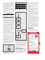
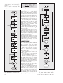
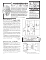
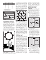
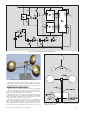
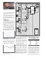
LISTING 3
DATA 01111110
DATA 10110000
DATA 21101101
DATA C1001110
DATA c0001101
DATA D0000000
DATA d0111101
DATA K0000000
DATA k0000000
DATA “ 0000000”
DATA “^1100011”
Fig.15. Example of PC screen during
digit control.
Consequently, do not switch on the PIC
unit until you see the screen now being discussed. When you have switched on the
PIC, then enter the number of digits to be
controlled and press <ENTER>.
The program then enters its full operational mode, first drawing on screen the
same number of boxes as the number of
digits specified. These boxes represent the
7-segment digits and display the same
characters.
Next the program sends data for numeral 8 to all digits required. It then sends a
reset command to the PIC, resetting it for
Digit 1, after which it sends data to clear all
required digits, again followed by a reset
command.
This action has three functions, to synchronise the PIC with the computer’s
order of digits, to prime the PIC so that it
knows which segments are in which state,
and thirdly to clear any existing display
data.
In the latter context it is worth recognising that the segments can be set by
hand without damaging them. They are
only balanced on light-duty pivots, freely
responding to the electromagnetic fields
generated by their coils. It is quite possible that someone could have set them by
hand to random positions. (In a “field”
situation, it is advisable to enclose the
digits to prevent this happening – and of
course to protect them from the
“elements”.)
From this point onwards, pressing any
recognised key causes the data to be displayed sequentially, with the count returning to zero (Digit 1) after the final digit (or
on pressing <ENTER> as described
earlier). An example PC screen display is
shown in Fig.15.
PC CONTROL DATA
OPTIONS
Because of the greater variety of segment codes that can be generated via the
PC than with the keypad, there is the
option to program the PC software with
any segment combination required.
The data is held in a look-up table
which can be added to by readers who
have QBasic or QuickBASIC resident on
their PC. The data is held as in the format
extract example shown in Listing 3, in the
bit order of segments ABCDEFG (the
opposite order used by the PIC software’s
table).
332
When the program
is started, all data
statements are “Read”
and analysed. The first character in each
data string holds the keyboard character
that represents the following 7-bit segment
data. Its ASCII value is taken and the
remaining seven bits in the data are stored
in a string array, seg$(x), at the address
corresponding to the ASCII value.
For example, in the first case,
“01111110”, the leading “0” is the first
character. Its ASCII value is 48 and so the
rest of the data string (“1111110”) is stored
at string array position seg$(48). In the
fourth case, “C” is the character, having the
ASCII value 67, so its 7-bit string data is
stored at seg$(67).
Note that some data statements have had
to be enclosed in quotes so that the program recognises the associated character
correctly (the last character in the above
list cause the “degrees” symbol to be displayed when the “^” is pressed (as in
20oC). The one before it is for the space bar
(turns off all segments in a digit).
You will see instances where the character may be in upper or lower case, and in
some cases both. If the value following the
character contains one or more “1”s, the
equivalent character can be generated on a
7-segment display. In the other cases, all
zeros, the character cannot be formed
using a 7-segment display.
If a character is not included in the table,
a value of zero is returned if its key is
pressed. All unacceptable keypresses are
ignored.
ALLOCATING
SEGMENTS
For such “unacceptable” keys, however, a
segment or PIC control code can be allocated separately. For instance, the program allocates the code “00000001” when the
<ENTER> key (ASCII 13) is pressed. The
PIC has been programed to recognise this bit
combination as the command to reset the
digit number count to Digit 1, in a similar
way to that in which it responds when the
“D” key on the 4 × 4 data keypad is pressed.
You could, for example, allocate specific codes for the PC’s forwards/backwards
cursor keys. The PIC could then be told to
step the digit count value backwards or
forwards without causing the display data
to change. Then, on pressing another key,
its character would be displayed at the new
digit address.
Such a facility would be of help in a display having many digits and where only
one or two might need to be changed at any
time. This would remove the need to key in
data for all digits in the full display when
only a few might need changing.
Another option open to those who are
familiar with QB programming is to write
a code routine that allows a string of characters to be entered via the keyboard as a
sentence (using INPUT instead of
INKEY$). This would not be transmitted
to the PIC until the <ENTER> key had
been pressed. Each character would then
be sent automatically in sequence to successive digits as required.
SETTING PULSE
LENGTH
So far the discussion has assumed that
the length of the control pulse that activates
the segment coils is correct. Setting preset
VR1 earlier to a fully clockwise position
sets the length to the maximum design
limit. It is likely that the pulse can be shortened, so speeding segment changes.
The simple data sheet received indicated
that a pulse length of about 0·25 seconds
was required. Experiments with the digits
showed that it could be much shorter.
Although there was a slight variation in
minimum operational pulse length for the
various segments, the requirements were
typically found to be about 70 milliseconds, but cannot be guaranteed in other
assemblies (hence the need for user-adjustment rather than specifying the length as
an accurate timing within the software).
A 70ms pulse length is generated with
preset VR1 at a roughly midway setting.
The maximum pulse length that can be set
is about twice that. These figures are based
on the PIC being run at 4MHz.
Once you have ascertained the correct
response of the segments using a long
pulse set via VR1, it is worth experimenting to find the lowest VR1 setting at which
the segments will respond. This will speed
the rate at which the displays can be
changed.
The digits will not respond if the resistance is set too low. An intermediate stage
may also be found in which some digits
respond but not others. Avoid setting VR1
to a nil resistance position which will overload RA4 when it is in output-low mode
(the PIC is internally protected against
brief overloads – but do not sustain this
condition).
It is worth noting that the software has
also been written to speed segment
changing. The status of each segment is
recorded in the PIC’s memory. When a new
character is to be displayed on a particular
digit, the digit’s current segment status is
checked against the segment requirement
for the new character. If any segments
match, they are ignored by the output routine, so saving one pulse duration – which
can be a significant saving when many
digits are in use.
SCHMITT PULSING
This now brings us to a software/hardware aspect that has not been used before
in an EPE project – analogue control of
frequency via a digital input.
You are no doubt familiar with the type
of circuit in which a single Schmitt trigger
inverter is used with a resistor and capacitor in order to generate a frequency (an RC
oscillator). The technique used in Big Digit
is similar.
The PIC16F84 has a Schmitt trigger
input, pin RA4. Referring to Fig.7, the
Everyday Practical Electronics, May 2002