1
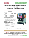
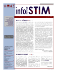
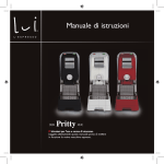
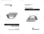
Please refer to the Lancer web site (www.lancercorp.com) for
information relating to Lancer Installation and Service Manuals,
Instruction Sheets, Technical Bulletins, Service Bulletins, etc.
INSTALLATION AND SERVICE MANUAL
FOR
MDS - 8000
MODULAR DISPENSING SYSTEM
This Manual supersedes Installation and Service Manual 28-0621/03, dated 07/31/97.
6655 LANCER BLVD. • SAN ANTONIO, TEXAS 78219 USA • (210) 310-7000
FAX SALES
• NORTH AMERICA – 210-310-7245 • INTERNATIONAL SALES – 210-310-7242 • CUSTOMER SERVICE – 210-310-7242 •
• LATIN AMERICA – 210-310-7245 • EUROPE – 32-2-755-2399 • PACIFIC – 61-8-8268-1978 •
FAX ENGINEERING: • 210-310-7096
"Lancer" is the registered trademark of Lancer • Copyright — 1999 by Lancer, all rights reserved.
DATE:
03/10/99
P.N. 28–0621/04
TABLE OF CONTENTS ......................................................................................................................................i
1. INSTALLATION ...........................................................................................................................................1
1.1 COUNTER SELECTION ....................................................................................................................1
1.2 PROVIDING CLEARANCE ................................................................................................................1
1.3 WATER REQUIREMENTS.................................................................................................................1
1.4 CARBON DIOXIDE (CO2) REQUIREMENTS....................................................................................1
1.5 ELECTRICAL REQUIREMENTS .......................................................................................................1
1.6 DRAIN REQUIREMENTS ..................................................................................................................1
1.7 SEALING THE DISPENSER TO THE COUNTER.............................................................................1
1.8 REQUIRED TOOLS FOR INSTALLATION ........................................................................................2
1.9 RECEIVING........................................................................................................................................2
1.10 UNPACKING ......................................................................................................................................2
2. ASSEMBLING THE DISPENSER..........................................................................................................2-15
3. ILLUSTRATIONS AND PARTS LISTINGS ...............................................................................................16
3.1 TEMPLATE, CUTOUT, COUNTER, RH ICE DISPENSER (NO BASE) ..........................................16
3.2 TEMPLATE, CUTOUT, COUNTER, LH ICE DISPENSER (NO BASE) ...........................................17
3.3 WRAPPER ASSEMBLY ..............................................................................................................18-19
3.4 MARQUEE AND LIGHT BOX ASSEMBLY .................................................................................20-21
3.5 SHROUD ASSEMBLY.................................................................................................................22-23
i
1. INSTALLATION
1.1 COUNTER SELECTION
A. Select a location close to a properly grounded electrical outlet (see Section 1.5, Electrical
Requirements) and water supply that meet the requirements outlined below.
B. Counter location must be able to support a minimum of 600 pounds (272 kg) per MDS unit.
NOTE
If two (2) systems are installed, the counter must be able to support 1,200 pounds (544 kg).
C. Counter cutouts, required for installation of unit, are shown in Sections 3.1 and 3.2. Full size
templates are provided with the MDS Kit.
1.2 PROVIDING CLEARANCE
WARNING
FAILURE TO MAINTAIN PROPER AIR CLEARANCE WILL CAUSE THE COMPRESSOR TO
OVERHEAT AND WILL RESULT IN PREMATURE COMPONENT FAILURE.
Condenser air is drawn in the top front of the unit and discharged out the top back of the unit. A
minimum of 15 inches (38.1 cm) clearance must be maintained over the top of the unit.
1.3 WATER REQUIREMENTS
CAUTION
IF WATER SOURCE EXCEEDS 50 PSIG (3.52 KG/CM2), A WATER REGULATOR ASSEMBLY
MUST BE USED TO LIMIT WATER PRESSURE TO 50 PSIG (3.52 KG/CM2). FAILURE TO USE
REGULATOR WILL RESULT IN IMPROPER PERFORMANCE OF DISPENSER.
This dispenser incorporates a built-in cold carbonator. There are three (3) water inlets to the
dispenser. Two (2) (plain water circuits) supply water to the non-carbonated drinks and one (1)
(prechill circuit) supplies the carbonator pump.
A. Plain Water Circuit Requirements
Minimum flowing pressure of 40 PSIG (2.81 kg/cm2, 2.75 BAR).
B. Prechill Water Circuit Requirements
Minimum flowing pressure of 25 PSIG (1.76 kg/cm2, 1.72 BAR).
Maximum static pressure of 50 PSIG (3.52 kg/cm2, 4.13 BAR).
1.4 CARBON DIOXIDE (CO2) REQUIREMENTS
Operating pressure: 75 PSIG (5.27 kg/cm2, 5.18 BAR).
1.5 ELECTRICAL REQUIREMENTS
WARNING
ALL ELECTRICAL CIRCUITS MUST MEET LOCAL BUILDING CODES.
DISPENSER MUST BE SUPPLIED WITH A SEPARATE ELECTRICAL CIRCUIT.
EACH DRINK
The drink dispenser must have an independent 115 Volt, 60 Hz, 20 Amp grounded circuit. The ice
dispenser should be connected per the manufacturer’s recommendations.
NOTE
The Ice Dispenser Installation Manual can be found in the ice bin.
1.6 DRAIN REQUIREMENTS
A drain connection should be located within three (3) feet of the dispenser.
1.7 SEALING THE DISPENSER TO THE COUNTER
The equipment should be permanently sealed to the counter using Lancer Sealant (PN 15-0010),
or equivalent.
1
1.8 REQUIRED TOOLS FOR INSTALLATION
The following tools will be required for installation:
A.
B.
C.
D.
E.
1.9
Screw Driver, Flat Head
Screw Driver, Phillips Head
Wrench, 7/16 inch
Beverage Tubing Cutter
Oetiker Clamp Crimper
RECEIVING
Each kit is thoroughly inspected before shipment. At time of shipment, the carrier accepts the unit(s)
and any claim for damages must be made with the carrier. Upon receiving unit(s) from the
delivering carrier, carefully inspect carton(s) for visible indication(s) of damage. If damage exists,
have carrier note same on bill of lading and file a claim with the carrier.
1.10 UNPACKING
A.
B.
C.
D.
E.
Carefully cut steel band and remove.
Remove top portion of carton by lifting up.
Remove accessory kit and loose parts from top packaging.
Remove top inner carton, pad and corners.
Using proper lifting techniques, lift unit up by plywood shipping base, and remove lower portion
of carton.
F. Inspect unit for concealed damage. If evident, notify delivering carrier and file a claim against
same.
G. Remove plywood shipping base from unit by locating unit so that one side is off the counter top
or table, allowing access to screws on the bottom of the plywood shipping base.
NOTE
If unit is to be transported, it is advisable to leave unit secured to plywood shipping base.
2. ASSEMBLING THE DISPENSER
STEP 1
A. To form the outer shell of the dispenser, position the left panel next to the back panel. Carefully
align the clips on each panel (see photo 1). Lift the left panel slightly and drop onto back panel
so that clips mate. Repeat the procedure to attach the right panel to the back panel (see
photo 2).
Photo 1
Photo 2
2
B. Prior to attaching the base plate to the partially completed shell, ensure that the left and right
panels are slightly spread open (see photo 3) to accommodate the base plate. Carefully align
the base plate to the side and back panels (see photo 4).
C. Secure the base plate to the panels with two screws (see photo 5) at the bottom, front of the left
and right hand panels.
Photo 3
Photo 4
STEP 2
A.
Place the two (2) “sliders” into temporary positions on the base plate (see photo 6). The
purpose of the sliders is to ease the installation of the dispenser unit into the frame. This will
keep the screw heads on the bottom of the dispenser from prematurely seating into the holes
on the base plate, until the proper time for final alignment.
B.
The sliders will be removed in a following step.
Photo 6
Photo 5
3
STEP 3
A.
Position the Dispenser unit near the dispenser shell. Due to the weight of the dispenser, it is
recommended that two persons lift the dispenser into the shell.
STEP 4
A.
Using proper lifting techniques, carefully lift the dispenser (see photo 7) and place into the shell.
B.
Insuring that the two sliders remain aligned, slide the dispenser unit into the shell.
STEP 5
A.
Lifting the dispenser unit slightly, carefully pull the “sliders” out of the shell (see photo 8).
B.
Slightly joggling the dispenser unit, insure that the screw heads on the bottom of the dispenser
have properly aligned and seated into the holes on the base plate.
C.
Save the “sliders” with the shipping carton in the event that the dispenser unit needs to be
removed and reinstalled.
Photo 7
Photo 8
STEP 6
A.
Prepare the ice dispenser unit for installation into the shell of the dispenser. Please note, in
photo 10, that the water bracket has been attached with four (4) screws.
STEP 7
A.
Using proper lifting techniques, lift the ice dispenser into the shell (see photo 10).
Photo 9
Photo 10
4
STEP 8
A.
Install splash plate bracket (see photo 11).
STEP 9
A.
Lift the bonnet to the top of the dispenser unit and align this part to the top of the dispenser (see
photo 12).
Photo 11
Photo 12
Photo 13
5
STEP 10
A.
Loosen but do not remove the four (4) screws securing the front plate (see photo 14).
STEP 11
A.
Remove the front plate from the notches (see photo 15).
Photo 15
Photo 14
STEP 12
A.
Connect wiring harness from the bonnet to the “AC” outlet (see photo 16) identified on the
dispenser unit.
STEP 13
A.
Plug in wiring harness to the key lock (see photo 17).
Photo 16
Photo 17
6
STEP 14
A.
Install front support (see photo 18). Secure with six (six) screws by installing the first two screws
in the top positions (see photo 19).
Photo 19
Photo 18
STEP 15
A.
Install marquee gas shocks (left and right) (see photo 20). Secure each to bracket with one (1)
shoulder screw each.
B.
At this time, securely tighten the six (6) screws from the preceding step, securing the front
support to the bracket. Insure that the bracket and the front support are evenly aligned.
STEP 16
A.
Install gas shocks (left and right) which will hold the light box (see photo 21). Secure each to
bracket with one (1) shoulder screw each.
Photo 20
Photo 21
7
STEP 17
A.
Install the light box by very carefully dropping and sliding it onto the brackets (see photo 22).
STEP 18
A.
Install two (2) hinge retainers (see photo 23).
B.
Secure each hinge retainer with two (2) screws (see photo 24).
Photo 22
Photo 23
STEP 19
A.
Secure left and right gas spring supports to light box using one (1) shoulder screw for each side
(see photo 25).
Photo 24
Photo 25
8
STEP 20
A.
Plug in wiring harness for light box to the dispenser front plate cover (see photo 26).
Photo 26
STEP 21
A.
Install bottom valve shroud bracket (see photo 27).
B.
Secure with four (4) screws, two (2) at each end of the shroud (see photo 28). At this time,
screws should only be finger snug as the shroud and screws will be adjusted in a later step.
Photo 28
Photo 27
9
STEP 22
A.
Install right hand (RH) splash plate bracket to dispenser (see photo 29). Secure with two (2)
screws.
Photo 29
STEP 23
A.
Install shroud assembly for valves (see photo 30).
B.
Attach shroud assembly with two (2) shoulder bolts (see photo 31).
C.
With the shroud open, install left and right latch pins. (see photo 32 and 33, next page.)
Photo 31
Photo 30
10
Photo 33
Photo 32
STEP 24
A.
Connect wiring harnesses to each of the six (6) valves (see photo 34).
B.
Connect wiring harness to the ice dispenser.
NOTE:
Ensure wiring harnesses are properly connected.
STEP 25
A.
Close valve shroud (see photo 35).
Photo 35
Photo 34
11
STEP 26
A.
Install splash plate to unit by sliding it up and inserting it into tabs at the top (see photo 36).
B.
Secure with two screws (see photo 37). Handtighten screws only at this step.
Photo 37
Photo 36
STEP 27
A.
Install cup rest to splash plate (see photo 38 and 39). Secure with six (6) screws.
Photo 39
Photo 38
12
STEP 28
A.
Install cup rest (see photo 40).
Photo 41
Photo 40
STEP 29
A.
Attach marquee to brackets (see photo 42).
Photo 42
13
STEP 30
A.
Install hinge retainers to secure marquee to brackets (see photo 43 and 44).
Photo 43
Photo 44
STEP 31
A.
Attach marquee to gas shocks (see photo 45).
B.
Close marquee.
STEP 32
A.
Slightly loosen the screws securing the marquee (see photo 46).
B.
The marquee should self-align.
C.
Secure screws attaching the marquee.
Photo 45
Photo 46
14
STEP 33
A.
Lift latch (both sides) to unlock valve shroud (see photo 47).
B.
Slide valve shroud out partially.
STEP 34
A.
Adjust shroud alignment to eliminate gap on each side (see photo 48).
B.
Securely tighten the screws.
Photo 47
Photo 48
Photo 49
15
2"
(5.080 cm)
2 3/4"
(6.985 cm)
16
3" (7.620 cm)
FOLD ALONG THIS LINE AND PLACE AGAINST EDGE OF DRAIN PLAN
TYPICAL, TWO PLACES,
R = 5/8"
4 3/4" (12.065 cm)
CUT OUT
THIS AREA
TYPICAL, TWO PLACES,
R = 1"
NOTE: FULL SIZE TEMPLATE IS PROVIDED WITH INSTALLATION KIT
CUT OUT THIS AREA
20"
(50.800 cm)
32 1/4"
(81.915 cm)
OUTLINE OF MDS 8000 UNIT
40 1/2"
(102.870 cm)
23 1/8"
(58.738 cm)
3.1
TEMPLATE FOR COUNTER TOP CUTOUT FOR
MDS 8000 WITH RIGHT-HAND ICE DISPENSER (NO BASE)
3. ILLUSTRATIONS AND PARTS LISTINGS
TEMPLATE, CUTOUT, COUNTER, RH ICE DISPENSER (NO BASE)
23 1/8"
(58.738 cm)
17
TYPICAL, TWO PLACES,
R = 5/8"
CUT OUT
THIS AREA
CUT OUT THIS AREA
20"
(50.800 cm)
32 1/4"
(81.915 cm)
NOTE: FULL SIZE TEMPLATE IS PROVIDED WITH INSTALLATION KIT
FOLD ALONG THIS LINE AND PLACE AGAINST EDGE OF DRAIN PLAN
4 3/4" (12.065 cm)
3" (7.620 cm)
TYPICAL, TWO PLACES,
R = 1"
OUTLINE OF MDS 8000 UNIT
40 1/2"
(102.870 cm)
2 3/4"
(6.985 cm)
2"
(5.080 cm)
TEMPLATE FOR COUNTER TOP CUTOUT FOR
MDS 8000 WITH LEFT-HAND ICE DISPENSER (NO BASE)
3.2
TEMPLATE, CUTOUT, COUNTER, LH ICE DISPENSER (NO BASE)
23
22
20
19
24
16
14
18
15
17
21
5
18
19
24
3
SIX VALVE, RIGHT HAND ICE DISPENSER ILLUSTRATED
13
W
A
T
E
R
12
11
10
9
8
7
6
25
4
1
26
OPTIONAL FOR UNITS
WITH DRAIN PANS
27
2
3.3
WRAPPER ASSEMBLY
3.3
WRAPPER ASSEMBLY (CONTINUED)
ITEM PART NO.
DESCRIPTION
1
R2
R3
4
5
6
-
Wrapper, Back Side
Wrapper, Right Side
Wrapper, Left Side
Base Frame Assembly, Universal
Bracket Assy, Splash Plate, Left
Bracket Assy, Splash Plate, Right
Bracket Assy, Spash Plate,
Universal, 40 Inch Base
Bracket Assy, Spash Plate,
40 Inch Base
Elbow, Swivel, Hose Assy
Seal, Washer, 7/16 Inch, 20M Flare
Nut, 7/16 - 20 x 0.250, SST
Bracket, Water Valve,
Right Ice Dispenser
Bracket, Water Valve,
Left Ice Dispenser
Spacer, Water Valve
Water Valve
Handle
Pin, Handle
Decal, Water Valve
Hinge, End Support
Hinge, Center
Front Brace, Sub Assy
Label, Wiring Diagram
Label, Plumbing Diagram, 6 Valve
Label, Plumbing Diagram, 8 Valve
Shocks, Gas, 20 Pound
Splash Plate Assy, RH, Ice Dispense
Splash Plate Assy, LH, Ice Dispense
Splash Plate Assy, RH, 40 Inch
Splash Plate Assy, LH, 40 Inch
Thumb Screw, Splash Plate
Frame, Cup Rest, 6 Valve
Frame, Cup Rest, 8 Valve
Frame, Cup Rest, 6 Valve,
40 Inch Base
Frame, Cup Rest, 8 Valve,
40 Inch Base
Cup Rest, Wire, Target, 6 Valve
Cup Rest, Wire, Target, 8 Valve
Screw, Shoulder
Drip Tray Assy, 40 Inch Base (Optional
for Units with Drain Pans)
Cuprest, Wire, 40 Inch Base (Optional
for Units with Drain Pans)
Base Assy, 40 Inch (Optional for Units
with Drain Pans)
51-5564
51-5570/01
51-5571/01
51-5602
51-5580
51-5318
51-5381
-
51-5383
7
8
9
10
01-0424
05-0011
04-0002/01
30-6506
-
30-6529
11
12
RR13
14
15
16
17
18
19
20
21
22
-
04-1041
19-0346
05-1403
03-0280
06-1720
30-7119
30-7120
51-5316
06-1717
06-1716
06-1393
81-0508
51-5315
51-5335
51-5342
51-5377
04-1042
30-6524
30-6568
30-6547
-
30-6668
23
24
25
23-1074
23-1075
04-1053
51-5339
26 23-1081
27 51-5338
R in margin indicates revision or change.
19
2
5
6
1
3
4
3
10
7
8
9
11
12
15
19
14
16
13
17
BA
LL
AS
T
18
3.4
MARQUEE AND LIGHT BOX ASSEMBLY
20
3.4
MARQUEE AND LIGHT BOX ASSEMBLY (CONTINUED)
ITEM PART NO.
DESCRIPTION
1
2
3
4
R5
6
7
8
9
10
11
12
R13
14
15
16
17
18
19
Marquee, Graphic Rails
Hinge Assy, Marquee
Lens, Marquee
Graphics, Marquee, Thirst On Ice
Bearing, Support, Marquee
Extrusion, F-Channel
Frame Assembly, Marquee
Lamp, 36 Inch, 30W, Daylight
Socket
Housing, Light Box
Hinge Assy, Light Box
Ballast, 115V/60HZ
Ballast, 230V/50HZ
Ballast, 220V/60HZ
Label, Wiring Diagram, Lightbox
Brace Assy, Light Box
Cover, Wiring, Left
Bracket, Strain Relief
Cover, Wiring, Right
Bracket Assy, Gas Shock, Right
Bracket Assy, Gas Shock, Left
05-1559
51-5574
27-0050
06-1723-02
10-0390/01
05-1331
51-5309
12-0262
12-0119
30-6494
51-5576
12-0129
12-0169
12-0282
06-1796
51-5317
30-7328
30-7327
30-7329
51-5333
51-5321
NOTE: R in margin indicates revision.
21
22
1
R
SO
D
ON
A
LY
T
W A
2
6
7
3
4
5
13
14
15
18
SIX VALVE, RIGHT HAND ICE DISPENSER ILLUSTRATED
8
9
10
11
16
12
17
3.5
SHROUD ASSEMBLY
E
3.5
SHROUD ASSEMBLY (CONTINUED)
ITEM PART NO.
1
2
3
4
5
6
7
8
9
10
11
12
13
14
15
06-1676
06-1674
06-1770
06-1677
06-1755
06-1754
06-1746
06-1753
06-1761
06-1765/01
06-1745
06-1767
06-1769
06-1772
06-1773
06-1774
06-1775
06-1756
06-1744
06-1675
06-1776
06-1750
06-1759
06-1679
05-1213
12-0259
05-1214/01
02-0502
12-0216
06-1681
05-1563
05-1553
05-1549
05-1551
12-0199
10-0502
05-1564
05-1554
05-1550
05-1552
10-0501
30-7145
51-5310
04-1053
16
51-5320
-
51-5334
-
51-5350
-
51-5352
17
18
30-6501
30-6500
DESCRIPTION
Label, Coca-Cola Classic
Label, Diet Coke
Label, Caffeine Free Diet Coke
Label, Sprite
Label, Cherry Coke
Label, Diet Sprite
Label, Nestea Unsweetened Iced Tea
Label, Nestea Sweetened Iced Tea
Label, Nestea Lemon Iced Tea
Label, Hi-C Fruit Punch
Label, Hi-C Pink Lemonade
Label, Hi-C Orange
Label, Fanta Orange
Label, Fanta Grape
Label, Fanta Fruit Punch
Label, Fanta Red Cream Soda
Label, Fanta Strawberry
Label, Barq's Root Beer
Label, Minute Maid Orange
Label, Mr. Pibb
Label, Fresca
Label, Mello Yello
Label, Dr.Pepper
Label, Ice
Housing, Bottle Cap
Switch, Bottle Cap Button
Holder, Switch, Ribbed
Gasket, Bottle Cap Button
Boot, Splash Proof
Decal, Soda Water Only
Shroud, Right Ice, 6 Valve
Shroud, Left Ice, 6 Valve
Shroud, Right Ice, 8 Valve
Shroud, Left Ice, 8 Valve
Switch, Soda Water Only
Knob, Slide
Slide, Shroud, Right Ice, 6 Valve
Slide, Shroud, Left Ice, 6 Valve
Slide, Shroud, Right Ice, 8 Valve
Slide, Shroud, Left Ice, 8 Valve
Bearing, Slide
Bracket, Shroud, Slide
Frame Assy, Shroud
Screw, Shoulder, Gas Shocks and
Valve Cover
Bracket Assy, Valve Cover, 6 Valve,
Right Ice
Bracket Assy, Valve Cover, 6 Valve,
Left Ice
Bracket Assy, Valve Cover, 8 Valve,
Right Ice
Bracket Assy, Valve Cover, 8 Valve,
Left Ice
Pin, Latch, Left
Pin, Latch, Right
23
NOTES
24
Directory of USA - Canada Offices,
International Offices, and Authorized Distributors
(Continued from previous page)
EcuaLancer S.A. - Ecuador
Lancer Sales Company
Contact: Luciano Lopez
Sector Las Acacias
Luis De Beethoven #958
Y Capitan Rafael Ramos
Quito, Ecuador
Phone: 593-22-401-598, 400-937, 406-418
FAX: 593-22-400-535
e-mail: [email protected]
Lancer Authorized Distributors
Eximport & Barter Co. - Caribbean
2101 S.W. 56th Terrace
Hollywood, FL 33023 USA
Phone: (954) 967-9999
FAX: (954) 967-9900
e-mail: [email protected]
PromoVen, S.A. - Argentina
Contact: Rafael Mendoza
Juncal 858 - Piso 3 Depto. “L”
(1062) Buenos Aires
Argentina
Phone: (54.11)4394.7654
FAX: (54.11)4394.1193
e-mail: [email protected]
Bras Sulamericana LTDA. - Brasil
Contact: Fabio Queiroz
Rua. Dr. Ladislau Retti, 1400
Parque Alexandre
Cotia Sao Paulo - Brasil
CEP: 06714-150
Phone: 55-11-4612-1122
FAX: 55-11-4612-2219
e-mail: [email protected]
Lancer Chile Ltda. - Chile
Contact: Heriberto Concha
Vicuna Mackenna 3019, San Joaquin
Santiago, Chile
Phone: 56-2-552-1657
FAX: 56-2-552-1961
e-mail: [email protected]
Lancer Pacific
International Sales
6655 Lancer Blvd.
San Antonio, TX 78219
Phone: (210) 310-7000
FAX: (210) 310-7242
1-800-729-1500
e-mail: [email protected]
Australia
Lancer Pacific Pty Ltd
5 Toogood Avenue
Beverley 5009
South Australia
Phone: 61-8-8268-1388
FAX: 61-8-8268-1978
e-mail: [email protected]
[email protected]
(for Fountain)
[email protected]
(for Beer)
Lancer Pacific Pty Ltd
7 Slough Avenue
Silverwater 2128
New South Wales
Australia
Phone: 61-2-9648-6840
FAX: 61-2-9648-6850
e-mail: [email protected]
(Managing Director)
[email protected]
(NSW State Manger)
Lancer Pacific Pty Ltd
55 Keele Street
Collingwood 3066
Victoria
Australia
Phone: 61-3-8415-1920
FAX: 61-3-8415-1929
e-mail: [email protected]
Lancer Pacific Pty Ltd
Unit 31, 284 Musgrave Drive
Coopers Plains 4108
Queensland
Australia
Phone: 61-7-3274-5700
FAX: 61-7-3875-1805
e-mail: [email protected]
New Zealand
Lancer Pacific Ltd
9 O’Rorke Street
Onehunga, Auckland
New Zealand
Phone: 64-9-634-3612
Mobile Phone: 64-21-745-389
FAX: 64-9-634-1472
e-mail: [email protected]
[email protected]
Lancer Asia
(Continued)
Freser (MALAYSIA) SDN. BHD. - Malaysia
No. 31, Jalan TPP 5/13, Taman
Perindustrian Puchong, Seksyen 5,
47100 Puchong, Selangor, Malaysia
Phone: 60-3-8061-6666
FAX: 60-3-8062-1007
e-mail: [email protected]
R.B.P. Industrial Sales Inc - Philippines
Unit 20, Facilities Centre Bldg.
548 Shaw Blvd
Mandaluyong City, Philippines
Phone: 632-531-1215/1221/1289
FAX: 632-531-1271
e-mail: [email protected]
Freser (S) Pte Ltd - Singapore
Blk 998 Toa Payoh North
#04-12/14
Singapore 318993
Phone: 65-6352-0943
FAX: 65-6352-8594
e-mail: [email protected]
Freser International Corporation - Taiwan
No. 76, Gui-Sui Street
Taipei 103, Taiwan R.O.C.
Phone: 886-2-2553-1555
FAX: 886-2-2553-2742
e-mail: [email protected]
Freser (Thailand) Co Ltd - Thailand
3/15 Moo 3, Soi Ruammitr
Tivanont Road, Banmai
Pakkred, Nonthaburi, 11120
Thailand
Phone: 662-961-9543
FAX: 662-961-9550
e-mail: [email protected]
Hong Kong
1001 Technology Plaza
651 King’s Road
North Point
Hong Kong
Patrick Co - Area Manager - Asia
Phone: 852-2214-9195
Rob Burdock - Senior Director - Asia
Phone: 852-2214-9196
FAX: 852-2214-9448
e-mail: [email protected]
[email protected]
Lancer - Indian Sub-Continent
Lancer Authorized Distributors
Shanghai Freser International Co Ltd. China
1856, Hu Tai Road
Shanghai, 200436, China
Phone: 86-21-5650-3555
FAX: 86-21-5650-2666
e-mail: [email protected]
India
Shabbir Shafiqui - Area Manager
India and Sub-Continent
B-7, Pannalal Silk Mill Compounds
78, LBS Marg, Bhandup (W)
Mumbai 400-078, India
Phone: 91-22-2561-6665
Cel No.: 91-98-2029-5252
FAX: 91-22-5637-4018
e-mail: [email protected]
Lancer Authorized Distributors
Freser (HK) Company Ltd - Hong Kong
Flat A, 24/F., Houston Industrial Bldg.
32-40 Wang Lung Street
Tsuen Wan, N. T., Hong Kong
Phone: 852-2408-2595
FAX: 852-2408-2605
e-mail: [email protected]
Western Refrigeration Ltd - India
B-7, Pannalal Silk Mill Compounds
78 L.B.S. Marg, Bhandup (W)
Mumbai 400-078, India
Phone: 91-22-2561-6665
FAX: 91-22-2562-2257
e-mail: [email protected]
P.T. Dikarunia Sejahtera - Indonesia
JI. Gelong Baru Tengah #1A, Tomang
Jakarta, Barat 11440, Indonesia
Phone: 62-21-5694-3242
62-21-5437-2534
FAX: 62-21-5694-3242
e-mail: [email protected]
Bengal Marketing Company - Bangladesh
Skylark Point (6th Floor)
Room #G-2
24/A Bijoy Nagar,
Dhaka-1000, Bangladesh
Phone: 880-2-934-2987
FAX: 880-2-935-0127
e-mail: [email protected]
Hayakawa Sanki - Japan
Hayakawa Sanki, Inc.
1-13-13, Kayaba-cho
Nihonbashi, Chuo-ku
Tokyo, 103-0025
Japan
Phone: 03-5651-1481
FAX: 03-5651-1445
e-mail: [email protected]
Tahoe Corporation - Korea
Tahoe Corporation
2FL, 835-66 Yocksam-dong
Kangnam-Ku
Seoul, Korea
Phone: 82-2-557-5612, -5614
FAX: 82-2-557-5615
e-mail: [email protected]
Dynamic Equipment - Pakistan
Dynamic Equipment and Controls (Pvt.) Ltd.
F-1/23, Canal Cottages, Block-D.
New Muslim Town.
Lahore. Pakistan.
Phone: 0092-42-583-6737
0092-42-583-6787
FAX: 0092-42-586-7924
e-mail: [email protected]
[email protected]
25
Directory of USA - Canada Offices,
International Offices, and Authorized Distributors
Corporate Office
6655 Lancer Blvd. • San Antonio, Texas 78219 • 210-310-7000 • 1-800-729-1500 • FAX 210-310-7250
Lancer USA
Manufacturing Locations
Foster Road Facilities
6655 Lancer Blvd
San Antonio, TX 78219
Phone: (210) 310-7000
MFG FAX: (210) 310-7088
ENG FAX: (210) 310-7096
ACCT FAX: (210) 310-7091
PURCH FAX: (210) 310-7094
Lancer FBD
5620 Business Park
San Antonio, TX 78218
Phone: (210) 666-0544
FAX: (210) 666-2044
Lancer Ice Link
6655 Lancer Blvd
San Antonio, TX 78219
Phone: (210) 310-7174
FAX: (210) 310-7245
Remanufacturing
6655 Lancer Blvd
San Antonio, TX 78219
Phone: (210) 310-7256
FAX: (210) 310-7261
1-800-729-1550
Lancer North America
USA - Canada Sales
6655 Lancer Blvd.
San Antonio, TX 78219
Phone: (210) 310-7000
SALES FAX: (210) 310-7245
CUSTOMER SERVICE FAX: (210) 310-7250
1-800-729-1500
Georgia Office
1125 Northmeadow Parkway, Suite 116
Roswell, GA 30076
Phone: (770) 343-8828
FAX: (770) 475-8646
1-800-729-1750
Lancer Authorized Distributors
Advanced Beverage Solutions (ABS)
100 N. Gary Avenue, Suite C
Roselle, IL 60172
Phone: (847) 524-1707
(877) 814-2271
FAX: (847) 524-1710
www.absone.com
Bevco
6900 Camille Avenue
Oklahoma City, OK 73149
Phone: (405) 672-7770
FAX: (405) 672-7443
e-mail: [email protected]
Joe Kirwan Company
119 White Oak Lane
Old Bridge, NJ 08857
Phone: (732) 679-1900
FAX: (732) 679-9236
e-mail: [email protected]
L & M Beverage Equipment Co. Inc.
12510 Santa Fe Trail Drive
Lenexa, KS 66215
Phone: (913) 888-8988
FAX: (913) 888-9137
e-mail: [email protected]
(Update #48 - as of January 13, 2004)
Ernest F. Mariani Company
614 West 600 South
Salt Lake City, UT 84104
Phone: (801) 359-3744
FAX: (801) 531-9615
e-mail: [email protected], or
[email protected]
Intercom - Spain
Intercom
Avda. Concha Espina 8
28036 Madrid Spain
Phone: 34-91-564 6900
FAX: 34-91-564 3065
e-mail: [email protected]
Mark Powers & Company, Inc.
P.O. Box 72
1821 Henry Street
Guntersville, AL 35976
Phone: (256) 582-6620
FAX: (256) 582-8533
e-mail: [email protected]
Lancer Russia
Maurer Supply, Inc.
843 Rainier Avenue South
Seattle, WA 98144
Phone: (206) 323-8640
FAX: (206) 323-9286
e-mail: [email protected]
Simgo Ltd.
5122 Timberlea Blvd.
Mississauga, Ontario L4W 2S5
Canada
Phone: 905-602-5800
FAX: 905-602-5804
e-mail: [email protected]
Simgo (B.C.) Ltd.
16-8125 - 130th Street
Surrey, B.C. V3W 7X4
Canada
Phone: 604-590-4022
FAX: 604-590-1601
Lancer Europe
Belgium - European Central Office
Lancer Europe, S.A.
Mechelsesteenweg 592
B-1930 Zaventem
Belgium
Phone: 32-2-755-2390
FAX: 32-2-755-2399
e-mail: [email protected]
England
Managing Director
Contact: Paul Haskayne
Lancer G.B. Llp.
Unit 9 Prosperity Court, Midpoint 18
Middlewich CW10 OGD
Cheshire, United Kingdom.
Phone: 441606837711
FAX: +441606832705
e-mail: [email protected]
17 Bembridge Gardens
Ruislip, Middlesex
HA4 7ER, England
Phone: 44-1895672667
FAX: 44-1895637537
e-mail: [email protected]
Hungary
H-2100 Gödöllõ
Isaszegi út 67
Hungary
Phone: 36-28-417-179
FAX: 36-28416-881
e-mail: [email protected]
Lancer Authorized Distributors
Complete Beverage Services, Ltd.
Republic of Ireland and Northern Ireland
Gortrush Industrial Estate
Omagh County Tyrone
Northern Ireland
Office: 44-1662 250 008
FAX: 44-1662-252-991
26
Lancer International Sales, Inc.
Representation Office
Kashirskoe shosse, 65 (1), Office 505
Moscow 115583 Russia
Mail: Moscow, 115551, Mail Box #2, Russia
Mobile Phone: 7-095-991-7778
Office Phone: 7-095-727-4063
Office FAX: 7-095-727-4064
e-mail: [email protected]
Lancer Middle East / Africa
Elsayed Moniem - Technical Manager
Lancer Middle East/Africa
7 Mubarak Street
East Ain Shams 11311
Cairo, Egypt
Phone/FAX: 2-02-49-35-395
Mobile Phone (GSM): 2-010-500-4007
e-mail: [email protected]
Lancer Authorized Distributor
DispenseTech - South Africa
P.O. Box 17495
Sunward Park, 1470
South Africa
Phone: 27-11-397-7455
FAX: 27-11-397-7648
e-mail: [email protected]
Lancer Latin America
Latin America Sales
6655 Lancer Blvd.
San Antonio, TX 78219
Phone: (210) 310-7000
FAX: (210) 310-7245
1-800-729-1500
e-mail: [email protected]
Lancer de México, S.A. de C.V.
Contact: Gerardo Canales
Calle Lerdo De Tejada #544 PTE.
Col. Las Villas
San Nicolas De Los Garza, N.L.
Monterrey, N. L., México C.P. 66422
Phone: (52)-81-83-52-85-32
Phone: (52)-81-83-52-85-34
Phone: (52)-81-83-52-53-60
FAX: (52)-81-83-32-54-10
e-mail: [email protected]
Lancer de México, S.A. de C.V.
Branch Office, Mexico City
Contact: Carlos Lopez
Lancer de Mexico S.A. de C.V.
Sucursal Mexico D.F.
Calle: Centeotl No. 112
Colonia: La Preciosa
Delegacion: Azcapotzalco
Mexico D.F. C.P. 02460
Phone: (52)-55-53-53-89-28
Phone: (52)-55-53-53-89-26
Phone: (52)-55-53-53-88-60
Phone: (52)-55-53-53-88-21
FAX: (52)-55-53-52-46-30
e-mail: [email protected]
(Continued on reverse)