1
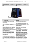
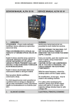
MG-001-03 PEGAS 160 E SERVICE MANUAL
SERVISNÍ MANUÁL PEGAS
160 E
1.
VAROVÁNÍ
UPOZORNĚNÍ – Pouze osoba splňující
kvalifikaci danou zákonem je oprávněna
opravovat stroj.
PŘED OTEVŘENÍM KRYTU STROJE JEJ
ODPOJTE VYTAŽENÍM SÍŤOVÉ VIDLICE ZE
SÍTĚ.
Každé 4 měsíce otevřete stroj a jemně ho
vyfoukejte stlačeným suchým vzduchem
POZOR, NEPOUŽÍVEJTE STLAČENÝ
VZDUCH O PŘÍLIŠ VYSOKÉM TLAKU, ABY
NEDOŠLO K MECHANICKÉMU POŠKOZENÍ
ELEKTROSOUČÁSTEK.
Každé 4 měsíce zkontrolujte řádný stav
svařovacích kabelů a síťových kabelů.
Není povolena žádná modifikace
svařovacího stroje.
Pro Vaši bezpečnost je nutné posečkat se
sundáním krytu ze stroje po odpojení ze sítě
po dobu minimálně 5 minut, kdy klesne
napětí na kondenzátorech na hodnotu pod
36 V.
ALFA IN a. s. © 2008
page 1
SERVICE MANUAL PEGAS
160 E
WARNING
NOTE Only trained personnel are
permitted to work inside the machine.
BEFORE OPENING THE MACHINE, CUT
OFF ITS ELECTRICAL POWER BY
REMOVING THE PLUG FROM THE
MAINS SUPPLY SOCKET.
Every six months, open the machine and
clean it inside, using compressed
dehumidified air.
CAUTION. DO NOT USE COMPRESSED
AIR AT TOO HIGH A PRESSURE. YOU
COULD DAMAGE THE ELECTRONIC
COMPONENTS.
With the same frequency, check the
welding cables and the supply cables.
No modification, of any type, may be
made to the welding machine.
For safety while maintaining the
machine, please shut off the supply
power and wait for 5 minutes, until
capacity voltage already drops to safe
voltage 36V.
SERVISNÍ TECHNICKÁ DOKUMENTACE
MG-001-03 PEGAS 160 E SERVICE MANUAL
2.
BLOKOVÉ SCHÉMA
ALFA IN a. s. © 2008
page 2
ELECTRICAL PRINCIPLE DRAWING
SERVISNÍ TECHNICKÁ DOKUMENTACE
MG-001-03 PEGAS 160 E SERVICE MANUAL
3.
NÁHRADNÍ DÍLY
Pos. Item No
page 3
SPARE PARTS
Popis
Description
Quantity
1
8.301.015
Kryt horní Pegas 160E
Cover upper Pegas 160E
1
2
7.232.729
Vypínač hlavní 30A Pegas
Switch ON/OFF 30A Pegas
1
3
7.154.402
Kabel přívodní Pegas
Mains Cable Pegas
1
ALFA IN a. s. © 2008
SERVISNÍ TECHNICKÁ DOKUMENTACE
MG-001-03 PEGAS 160 E SERVICE MANUAL
4
8.068.987-D Panel zadní Pegas 160 E
5
7.720.005
6
page 4
Back Panel PEGAS 160 E
1
Ventilátor PEGAS 160
Fan
1
7.411.010
Usměrňovač PEGAS 160 E
Rectifier Bridge
1
7
7.425.632
Tranzistor IGBT Discrete PEGAS 160 E Discrete IGBT
8
6.185.026-B Trafo hlavní Pegas
Main transformer Pegas
1
9
5.496.613-H PCB řídící Pegas 160E
Control pcb Pegas 160E
1
10
5.496.165-J
PCB silová Pegas 160E (10+22)
Main board Pegas 160E (10+22)
1
10
5.AAA.160E
PCB silová P160E kompl. (Obsahuje
položky 6-8+10+21-29)
PCB Power P160E compl. (Contains
Items 6-8+10+21-29)
1
10
5.AAR.160E
PCB silová P160E kompl. Repas
(Obsahuje položky 6-8+10+21-29)
PCB Power P160E compl. Repair
(Contains Items 6-8+10+21-29)
1
11
8.713.003
Izolace Pegas 160E
Inaulation Pegas 160 E
2
12
Front plastic panel Pegas
1
Front Panel Film 160E
1
14
Panel přední Pegas 160-200E
8.069.987
8.103.016Štítek panelový Pegas 160E
PE
7.458.033-B Knoflík Pegas
Knob Pegas
1
15
7.557.031
Rubber cap Pegas
1
16
7.152.313
Quick Connector Pegas 35-70
2
Front PCB (Contains Items 17-20)
1
Diode LED 5mm Green
1
13
Čepička gumová Pegas
4
18
Rychlospojka Pegas 35-70
PCB přední PEGAS (Obsahuje položky
5.496.872-A
17-20)
Dioda LED 5mm zelená
7.401.107
18
7.401.106
Dioda LED 5mm červená
Diode LED 5mm Red
1
19
7.456.148
Potenciometr 10K
Potenciometer 10k
1
20
7.222.013-B Přepínač KNX Pegas
Swith Pegas
1
21
6.271.003-B Tlumivka Pegas
Inductance Pegas
1
22
7.460.810
Kondenzátor kapacitní PEGAS 160
Capacitance
6
23
7.321.002
Sonda Hull 200A Pegas
Hull inductance 200A Pegas
1
24
8.425.025
Chladič 3 Pegas
Heat sink 3 Pegas
1
25
8.425.023
Chladič 1 Pegas
Heat sink 1 Pegas
1
26
8.123.637
Držák chladiče Pegas
Holder for heat sink Pegas
3
27
8.425.024
Chladič 2 Pegas
Heat sink 2 Pegas
1
28
7.231.275
Termostat PEGAS 160 E
Thermo switch
1
29
7.421.541
Dioda PEGAS 160 E
Diode
6
30
8.055.987
Kryt spodní Pegas 160E
Ground Pegas 160E
1
31
7.406.219
IO TC 4420 CPA
ICTC4420
2
17
4.
ZÁVADY - ŘEŠENÍ
Poř.
Závada
1
Stroj je zapnutý, ventilátor funguje, LED
zapnutí nesvítí
2
Stroj je zapnutý, LED zapnutí svítí,
ventilátor neběží.
ALFA IN a. s. © 2008
Příčina
Řešení
LED nebo její připojení je
vadné.
Silová PCB je vadná.
Překážka rotace ventilátor.
Motor ventilátor poškozen.
Opravte připojení nebo vyměňte
LED Pr3
Opravte nebo vyměňte PCB Pr2
Odstraňte
Vyměňte ventilátor
SERVISNÍ TECHNICKÁ DOKUMENTACE
MG-001-03 PEGAS 160 E SERVICE MANUAL
page 5
Není napětí v síti
Zkontrolujte, jestli je v síti napětí.
3
Stroj je zapnutý, LED zapnutí nesvítí,
ventilátor neběží.
Přepětí nebo podpětí v síti.
Zkontrolujte síťové napětí.
4
Žádné napětí na prázdno
Závada generátor.
5
Žádný svařovací proud na svorkách
Svařovací kabely nejsou
připojeny do konektorů.
Poškozený svařovací
Zkontrolujte hlavní obvod Pr1 a
Pr2
Připojte svařovací kabely do
rychlospojek na stroji.
Vyměňte nebo opravte svařovací
kabel.
kabel.
Zemnící kabel není připojen
nebo je špatně připojen.
6
Obtížně se zapaluje oblouk nebo dochází k
lepení elektrody.
Špatně utažené svařovací
kabely.
Svařenec je znečištěn
olejem nebo prachem.
MMA/TIG výběr je špatný.
7
8
9
Nestabilní svařovací oblouk.
Svařovací proud nelze nastavit.
Penetrace tavné lázně nedostačující.
ARC FORCE nastaveno
příliš nízké.
Poškozený potenciometr
předního panelu.
Svařovací proud je
nastaven příliš nízko.
ARC FORCE nastaveno
příliš nízké.
Nepříznivý vliv průvanu
Zkontrolujte zemnící kabel
Zkontrolujte utažení svařovacích
kabelů.
Očistěte svařenec.
Vyberte MMA svařování.
Zvyšte ARC FORCE.
Opravte nebo vyměňte
potenciometr.
Zvyšte svařovací proud
Zvyšte ARC FORCE.
Použijte zástěnu.
Změňte úhle uchycení elektroda
Excentrická elektroda
Vyměňte elektrodu
Nahněte elektrodu proti směru
magnetického vlivu.
10
Nestabilní oblouk
Vliv magnetismu
Změňte pozici zemnícího kabelu
nebo přidejte zemnící kabel na
opačnou stranu svařence.
11
Přehřátí
Stroj
zatížen
Ochrana
přepětí
Nestandardní
proud na
hlavním
obvodu.
LED ALARM svítí
příliš
Počkejte, až se stroj vychladí
Otestujte a opravte hlavní obvod
PCB (Pr1)
TROUBLESHOOTING
Troubles
S/N
1
2
Turn on the power source, and fan works,
but the power light is not on.
Turn on the power source, and the power
light is on, but fan doesn’t work
ALFA IN a. s. © 2008
Reasons
The power light damaged or
connection is not good
Power PCB failures
There is something in the
fan
Solutions
Test and repair the inside circuit
of power light Pr3
Repair or change power PCB
Pr2
Clear out
SERVISNÍ TECHNICKÁ DOKUMENTACE
MG-001-03 PEGAS 160 E SERVICE MANUAL
page 6
The fan motor damaged
No input voltage
Change fan motor
Check whether there is input
voltage
3
Turn on the power source, and the power
light is not on, and fan doesn’t work
Overvoltage (Input voltage
Check input voltage
is too much or not)
4
5
No no-load voltage output
No current output in the welding
There is trouble inside the
machine
Welding cable is not
connected with the two
output of the welder.
Welding cable is broken
Earth cable is not connected
or loosen
The plug loosen or connect
not well
Oil or dust covered the
6
Not easy to start arc in the welding, or easy
to cause sticking
workpiece
MMA/TIG welding selection
is wrong
7
The arc is not stable in the welding process
8
The welding current can not be
adjusted
9
The penetration of molten pool is not
enough(MMA)
The arc force is too small
The welding current
potentiometer in the front
panel connection not so
good or damaged
The welding current
adjusted too low
The arc force adjusted too
small
Airflow disturbance
Check the main circuit, Pr1 and
Pr2
Connect the welding cable to the
welder’s output
Wrap, repair or change the
welding cable
Check the earth clamp
Check and tighten the plug
Check and clear out
Selecting the MMA welding
Increase the arc force
Repair or change the
potentiometer
Increase the welding current
Increase the arc force
Use the shelter from airflow
Adjust the electrode angle
The electrode eccentricity
Change the electrode
Incline the electrode to the
opposite way of the magnetic
10
Arc blow
blow
Magnetic effect
Change the position of earth
clamp or add earth cable in the
two side of workpiece
Use the short arc operation
11
The alarm light is on
Over heat
protection
ALFA IN a. s. © 2008
Over
welding
current
Working
time too
long
Induce the welding current output
Induce the duty cycle (interval
work)
SERVISNÍ TECHNICKÁ DOKUMENTACE
MG-001-03 PEGAS 160 E SERVICE MANUAL
page 7
Over current
protection
5.
KONTROLA SILOVÉ PCB
Nástroj: standardní multimetr nastavený do
pozice “kontrola diod“.
Všechny komponenty proměřte nejdříve podle
řádku 1 tabulky a po té podle řádku 2.
ALFA IN a. s. © 2008
Unusual
current in
the main
circuit
Test and repair the main circuit
and drive PCB (Pr1)
CHECKING THE POWER PCB
Tool: standard multimeter set to the position
“Diode“
Measure all the components firstly
according line 1 and then according line 2
of the table.
SERVISNÍ TECHNICKÁ DOKUMENTACE
MG-001-03 PEGAS 160 E SERVICE MANUAL
ALFA IN a. s. © 2008
page 8
SERVISNÍ TECHNICKÁ DOKUMENTACE
MG-001-03 PEGAS 160 E SERVICE MANUAL
page 9
5.1 Měření tranzistorů T1, T2, T5 a T6
Line
Červený hrot/Red tester
1
Checking the transistors T1, T2, T5 a
T6
Černý hrot/Black tester
G
E
2
E
Pokud je jakákoli naměřená hodnota mimo
uvedený rozsah, je potřeba vyměnit vždy celý
pár tranzistorů (T1-T2 nebo T4-T5).
1. Součástku odletujte z PCB,
2. odšroubujte z chladiče,
3. odstraňte cín odsátím z otvorů PCB
4. očistěte chladič od teplovodné pasty
lihem,
5. naneste teplovodnou pastu na novou
součástku,
6. přišroubujte k chladiči
7. a zaletujte součástku k PCB
5.2 Měření diod D1 až D6
Line
Červený hrot/Red tester
1
0,20-0,25
G
0,20-0,25
It is always necessary to exchange a
complete couple of transistors (T1-T2 or T4T5) if any measured value is out of the
range.
1. Unsolder the component from
the PCB,
2. unscrew that from the heat sink,
3. suck away the tin from the holes in
the PCB
4. wipe off the heat transmitting paste
from the heat sink by means of spirit
5. spread on the new component the
heat transmitting paste,
6. screw the new component on
the heat sink,
7. solder the new component on the
PCB
Checking the diodes D1 – D6
Černý hrot/Black tester
A
2
K
Pokud je jakákoli naměřená hodnota mimo
uvedený rozsah je potřeba vyměnit vždy celý
pár diod (D1-D2, D3-D4 nebo D5-D6).
1. Součástku odletujte z PCB,
2. odšroubujte z PCB,
3. odstraňte cín odsátím z otvorů PCB
4. očistěte PCB od teplovodné pasty lihem,
5. naneste teplovodnou pastu na novou
součástku,
6. přišroubujte k PCB
7. a zaletujte součástku k PCB
ALFA IN a. s. © 2008
Hodnota/Value
K
Hodnota/Value
0,30-0,37
A
OL
It is always necessary to exchange a
complete couple of diodes (D1-D2, D3-D4
or D5-D6) if ony measured value is out of
the range.
1. Unsolder the component from
the PCB,
2. unscrew that from the PCB,
3. suck away the tin from the holes in
the PCB
4. wipe off the heat transmitting paste
from the PCB by means of spirit
5. spread on the new component the
heat transmitting paste,
6. screw the new component on
the PCB,
SERVISNÍ TECHNICKÁ DOKUMENTACE
MG-001-03 PEGAS 160 E SERVICE MANUAL
page 10
7. solder the new component on the
PCB
6.
DOPORUČENÉ NÁHRADNÍ DÍLY NA
SKLAD NA 100 KS ZAKOUPENÝCH
PEGASŮ 160 E
Kod
7.421.541
7.406.219
7.425.632
7.460.810
5.496.872-A
5.496.613-H
7.231.275
7.411.010
7.720.005
Worked out:
Název
Dioda PEGAS 160 E
IC TC 4420 CPA
IGBT Discrete PEGAS 160 E
Odpor kapacitní PEGAS 160
PCB přední PEGAS 160 E
PCB řídící PEGAS 160 E
Termostat PEGAS 160 E
Usměrňovač PEGAS 160 E
Ventilátor PEGAS 160
PAM/VH
23/1/2008
ALFA IN a. s. © 2008
Inspected:
RECOMEDED QUANTITY OF SPARE
PARTS FOR 100 PCS OF PURCHASED
PEGASES 160 E
Description
Diode
IC TC 4420 CPA
Discrete IGBT
Capacitance
Front PCB
Control board
Thermo switch
Rectifier Bridge
Fan
VH 23/1/2008
Quantity
12
4
8
8
2
2
2
2
2
Approved:
VH 23/1/2008
SERVISNÍ TECHNICKÁ DOKUMENTACE