1
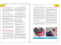
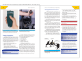
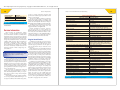
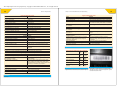
This sample chapter is for review purposes only. Copyright © The Goodheart-Willcox Co., Inc. All rights reserved.
C
H
A
P
T
E
R
1
3
Preventive Maintenance
and Troubleshooting
Learning Objectives
Key Terms
After studying this chapter, you will be able to:
compression gauge
compression test
coolant hydrometer
differential pressure test
digital tachometer
filler plug
hot spots
loaded oil
•
Perform preventive maintenance on various
engine systems, including the crankcase
breather, air cleaner, and muffler.
•
Keep engines clean.
•
Change the oil in a four-cycle engine.
•
Prepare an engine for storage.
•
Describe systematic troubleshooting.
•
Use manufacturer’s service manuals to
determine engine specifications and explain
why this information is necessary when
servicing a small engine.
Preventive Maintenance
S
E
C
T
I
O
N
4
Engine Service
Chapter 13. Preventive Maintenance and Troubleshooting
Chapter 14. Fuel System Service
Chapter 15. Ignition and Electrical System Service
Chapter 16. Engine Disassembly and Inspection
Chapter 17. Cylinder, Crankshaft, and Piston Service
Chapter 18. Camshaft and Valve Train Service
Chapter 19. Engine Reassembly and Break-In
Certain maintenance tasks must be performed
regularly to keep an engine working properly.
These tasks come under the heading of preventive
maintenance, because they help prevent premature engine wear and other engine problems.
Engine Cleaning
Cleaning a small air-cooled engine periodically
can help prevent overheating. For proper cooling
action, air must pass across the extended metal
surfaces (cooling fins) of the cylinder block and
cylinder head. If the cooling fins are insulated by
dirt, leaves, and/or grass clippings, engine parts
will retain most of the combustion heat. Parts will
expand, probably distort, and possibly seize. Therefore, all finned surfaces should be cleaned regularly.
optical tachometer
owner’s manual
preventive maintenance
reverse flushing
service manual
systematic
troubleshooting
thread chaser
Methods for cleaning small air-cooled engines
vary. Begin by removing any shrouds or engine
covers obstructing the cooling fins. You can then
blow debris from the fins with compressed air and
use a cleaning solvent to remove any remaining dirt
and oil. See Figure 13-1. Alternately, you can scrape
the dirty areas with a piece of wood and wipe them
with a clean cloth. Various multipurpose spray
cleaners are suitable for use on small engines.
Warning
When using compressed air, be extremely careful
where you direct the blast of air. Wear safety goggles.
Never direct the air blast toward skin or clothing.
In addition to cleaning cooling fins, be sure to
clean the engine crankcase area. This area also transfers a great deal of engine heat to the surrounding
air. A coating of dirt or oil will insulate the crankcase
and may contribute to engine overheating.
243
This sample chapter is for review purposes only. Copyright © The Goodheart-Willcox Co., Inc. All rights reserved.
244
Section 4 Engine Service
Figure 13-1.
This chain saw engine is being cleaned with
compressed air.
Figure 13-2.
Checking the oil is an important part of preventive
maintenance.
245
Chapter 13 Preventive Maintenance and Troubleshooting
The small engine manufacturer will recommend
oil changes at intervals based on hours of running
time. A new engine should have the first oil drained
after only a few hours of operation to remove any
metallic particles from the crankcase. After that, the
time specified may vary from 10–50 hours.
Engine oil does not wear out. It always remains
slippery. However, oil used for many hours of engine
operation becomes contaminated with dirt particles,
soot, sludge, varnish-forming materials, metal particles, water, corrosive acids, and gasoline. These contaminants eventually render the oil useless. The harm
they cause outweighs the lubricating quality of the oil.
The time interval for oil changes is selected so
that the oil never reaches a loaded level of contamination. Loaded oil cannot absorb any more contaminants and still be an effective lubricant. When
oil reaches a loaded condition, varnish deposits
begin to form on the piston and rings, and sludge
collects in the crankcase.
Note
Some
S
ome engines
engin
ines do
do nott have
h e an oilil drain
d i plug.
l
Oil mustt
be
b
e drained
drrain
ned through
throug
gh the filler
lle
er hole on these engines.
Clean the dirt from the drain plug area and
then remove the plug with a proper wrench,
Figure 13-5. Allow the oil to drain for approximately five minutes to remove as much contaminated oil as possible. See Figure 13-6. If the drain
hole is located on the side or top of the engine, tilt
the engine toward the drain hole if possible. When
draining is complete, replace the drain plug.
Checking Oil Level and Condition
Crankcase oil in four-cycle engines should be
checked periodically. Preferably, it should be checked
each time fuel is added. The engine manufacturer
provides a means of visually inspecting the level and
condition of the oil. Use the type and viscosity grade
of oil recommended by the manufacturer and maintain it at the proper operating level.
To check the oil level in engines equipped with
a dipstick, withdraw the dipstick and wipe it dry.
Reinsert the dipstick as far as it will go. Withdraw
it a second time and observe the oil level on the
dipstick. See Figure 13-2.
The markings on dipsticks may vary, but all will
have a Low (Add) mark and a Full mark. Add oil if the
level is at or below the Low mark. Do not run the engine
with oil showing above the Full mark on the dipstick. If
the crankcase oil level is high, drain some oil.
Changing Oil
Changing engine oil is not difficult. Begin by
running the engine until it is thoroughly warmed
up. Warm oil will drain more completely, and more
contaminants will be removed if the oil is agitated.
Turn off the engine and disconnect the spark
plug. The oil drain plug is located at a low point
on the crankcase, usually along the outside edge of
the base. See Figure 13-4.
Socket
Figure 13-5.
This technician is using a socket and ratchet to
remove the drain plug. The plug should be turned
counterclockwise for removal.
Plug
Figure 13-3.
A screwdriver can be used to remove the type of oil
filler plug shown here.
Caution
Overfi
O
verfifilli
lling
ing th
the
he crankcase
crrankcase
e with oil can foul plugs and
ccause
ause the engine
eng
gine
e to
o use
e too much oil.
Some small gasoline engines do not have dipsticks. Instead, they have a filler plug that threads
into the filler hole to seal out dirt and seal in the oil.
Figure 13-3 shows the proper method of loosening
one type of filler plug. When the plug is removed,
the oil level should be at the top of the filler hole or
to a mark just inside the filler hole.
If the engine oil level drops at an excessive rate
(requires the addition of oil frequently), look for
the cause. Refer to a troubleshooting chart for the
particular engine at hand. Troubleshooting charts
are covered later in this chapter. Typical causes of
excess oil consumption are external leaks, worn oil
seals around the crankshaft, worn valve guides,
worn piston rings, or a hot running engine.
The color of used oil is not always an accurate indication of its condition. Additives in the oil may change
its color without decreasing its lubricating qualities.
Drain plug
Drain plug
Figure 13-4.
Figure 13-6.
The oil drain plug is located at a low point in the
crankcase to permit oil to drain completely.
It may take several minutes for all the old oil to drain
from the engine.
This sample chapter is for review purposes only. Copyright © The Goodheart-Willcox Co., Inc. All rights reserved.
246
Section 4 Engine Service
If the engine is equipped with a disposable oil
filter, replace the filter each time the oil is changed.
To prevent oil leaks, always coat the filter’s O-ring
seal with a light coat of clean oil before installing
the filter. See Figure 13-7.
Before putting fresh oil in the engine, clean
the filler opening, funnel, and the top of the oil
container. Be sure to use the type, viscosity grade,
and quantity of oil recommended by the manufacturer. Pour the oil in the engine’s crankcase and
then check the level. See Figure 13-8. If the oil level
is correct, replace the filler cap and reconnect the
spark plug lead to the spark plug.
Gasket
Start the engine and allow it to run for a few
minutes. Then stop the engine and recheck the
oil level. Add oil as necessary. Finally, inspect the
drain plug and oil filter for oil leaks.
Lubricating Cables and Linkage
Oil filter
Clean the area around the filler opening, as well as the
funnel, before adding oil.
Spark plug
If any oil is left in the oil container, cap the container
tightly to prevent condensation or contamination.
Many
M
anyy m
manufacturers
anu
ufa
acturrers recom
recommend
mmend silicone-based
llubricants
ubriccan
nts fo
or use
e on cables and linkages. Unlike
for
petroleum-based
p
etro
oleu
um-b
based products, these lubricants will not
attract
they
applied.
a
ttra
act dirt
dirt after
after th
hey are ap
pplied.
Figure 13-8.
Housing
After
After cchanging
ha
angin
ng the
the oil, wash
wash oily rags or dispose of
th
hem properly.
properlyy. Storing
Storring them
th
hem may cause spontaneous
them
ccombustion.
ombustio
on. Spontaneous
Spo
onta
aneo
ous combustion occurs when
ccombustible
ombustib
ble
e material
matterial self-ignites.
Note
A typical disposable oil filter. To prevent leaks, apply a
light film of oil around the O-ring seal before installation.
Cable
Caution
Engine cables and linkage should be lubricated periodically to ensure smooth operation
and reduce the chances of binding and premature
wear. Linkage (throttle linkage, governor linkage,
etc.) can generally be lubricated by spraying it with
an appropriate lubricant.
Figure 13-7.
247
Chapter 13 Preventive Maintenance and Troubleshooting
To lubricate cables (throttle cable, engine bale,
etc.), place a few drops of the recommended lubricant between the cable and its housing at the highest end of the cable. Allow the lubricant to run down
between the cable and housing. Lubricant should
flow out of the low end of the cable. If it does not,
add a few more drops of lubricant and allow it to run
down the cable. Continue this process until clean
lubricant flows from the bottom end of the cable.
If desired, spray lubricant can be used to lubricate the cable. Simply spray the lube between the
cable and the housing, and watch for it to exit at
the low end of the cable. See Figure 13-9.
Some manufacturers produce a tool that provides a leak-proof connection between the tube
from a can of spray lubricant and the cable. When
this tool is used, the lubricant is forced under pressure through the cable, making lubricating cables
fast and easy. This type of tool is especially helpful when lubricating cables that run horizontally
rather than vertically.
Spray lubricant
Boot
Figure 13-9.
Figure 13-10.
Lubricant can be sprayed between the cable and the
housing.
When removing a spark plug wire from the plug, pull
on the boot only. Do not pull on the wire itself.
Wire-type
feeler gauge
Spark Plug Service
The spark plug should periodically be removed
for inspection and cleaned or replaced. Begin by
using compressed air to blow dirt away from the
base of the spark plug. Remove the spark plug wire
from the plug by pulling on the wire’s insulating boot
only. Do not pull on the wire itself. See Figure 13-10.
Install a deep spark plug socket on the plug
and carefully turn the ratchet handle counterclockwise. Unscrew the spark plug and remove it
from the cylinder head.
Carefully examine the electrode end of the
plug. The electrodes and ceramic insulator should
be dry. An insulator or electrodes that are wet with
fuel or oil may be a sign of serious engine problems. A dry insulator that has a beige or gray/tan
color indicates that the engine is in good condition.
Next, examine the electrodes for any erosion, burning, or carbon fouling. Refer to Spark Plug Condition
chart in the Appendix of this text.
If the spark plug insulator and electrodes
appear to be good (no evidence of fouling or
wear), the plug can be reinstalled. If not, install a
new plug of the correct type. Refer to the manufacturer’s technical service manuals for the proper
replacement spark plug.
Check the electrode gap with a wire-type feeler
gauge, Figure 13-11. The engine service manual
Figure 13-11.
A wire-type feeler gauge is being used to check spark
plug gap.
will specify the proper gap setting. If the gap is too
large, carefully bend the outer electrode toward the
center electrode until the gap is correct. Use the gap
setting tool.
Before installing the spark plug, clean the
external ceramic insulator by wiping it with a clean
cloth. Condensation can cause flashover (sparking
externally) and erratic running if the insulator has
a coating of dirt on it. If the metal base is rusty,
This sample chapter is for review purposes only. Copyright © The Goodheart-Willcox Co., Inc. All rights reserved.
248
clean it on a wire wheel or with a wire brush. If the
threads are dirty, they should be wiped clean or
wire brushed before inserting the plug back into
the spark plug hole. The gasket should be in good
condition or replaced with a new one.
Insert the spark plug in the spark plug hole and
turn it clockwise by hand until it stops. Be careful
not to cross thread the spark plug in the hole. If the
plug will not turn, do not force it. Remove it and
examine the threads in the hole. If they are damaged, a thread chaser (special thread tapping tool)
may be needed to clean and correct the threads.
If the spark plug turns smoothly by hand until
it seats, tighten the plug with a torque wrench to
13–15 lb ft. Do not overtighten.
Examine the spark plug wire for deterioration
before reinstalling it on the spark plug. Heat and
dirt can make the insulation brittle and insulation cracking can occur. Cracked wire insulation
can allow arcing to metallic parts of the engine
and cause hard starting and erratic running. Oilor fuel-soaked wires will leak current and cause
weak firing of the plug. The insulating boot should
be dry and in good condition.
Section 4 Engine Service
Air cleaner receptacle
A
Cloth
B
Air cleaner cover
C
Figure 13-12.
The cover on this air cleaner housing is held in place
by a screw.
Oil-wetted
air cleaner
D
Figure13-14.
The sequence for servicing a foam-type filter element is
shown. A—Wash the foam element thoroughly in liquid
detergent and water. B—Wrap the foam in cloth and
squeeze it dry. C—Saturate the foam with clean oil.
D—Squeeze out the excess oil.
Cover
Filter element
Figure 13-15.
The pleated paper should face the outside of the air
cleaner receptacle (away from the engine).
Pleated paper
filter
Caution
Never
N
ever use
use compressed
com
mpresssed
d air
i to
t clean
l
the
th paper fifilter
filt
lter
b
ecause the
e air
air ccan
an
n dam
mage the filter element. The
because
damage
damaged
lter may
d
amaged fifilter
may
y not prevent
prevent fine dirt from entering
the
engine.
th
he e
ngin
ne.
Air Cleaner Service
The air cleaner should be cleaned before each
season of operation and at regular intervals thereafter. Under severe dust conditions, air filters
should be cleaned more often. A plugged air filter
can cause hard starting, loss of power, and spark
plug fouling.
Three types of air cleaners widely used in
small gasoline engines are the oil-wetted (plastic
foam element) type, the dry type (pleated paper
element), and the dual-element type. Each has a
different method of cleaning and servicing.
Begin by removing the screw, wing nut, or
other fastening device to uncover the air cleaner
element. See Figure 13-12.
When servicing an oil-wetted filter element,
the element can be pulled from the receptacle after
the cover is removed. See Figure 13-13. Be careful
not to drop any dirt into the carburetor throat during this procedure.
To clean the element, wash it in liquid detergent
and water. Then rinse the element in clear water.
After washing the element, wrap it in dry cloth
and squeeze it dry. Absorbent toweling works well
for this procedure.
249
Chapter 13 Preventive Maintenance and Troubleshooting
Figure 13-13.
After the cover is removed, the element can be pulled
from the receptacle.
The plastic foam should be saturated with clean
engine oil. After saturating the element, squeeze
excess oil out of the foam. See Figure 13-14. Finally,
reassemble the air filter unit. Follow any special
instructions found in the owner’s manual for the
specific engine and filter.
Most dry-type air filter elements (pleated
paper) are designed to be thrown away when they
become dirty. Nevertheless, you can clean a pleated
paper filter element by tapping it on a flat surface
to dislodge light accumulations of dirt. However, if
the element will not tap clean, it must be replaced.
When installing a pleated paper-type air filter element, the pleated paper should face the
external side of the air cleaner receptacle. See
Figure 13-15.
Engines designed to be used in dusty conditions
may have dual-element air cleaners. Dual-element
air cleaners use a plastic foam filter pre-cleaner
that is mounted over a pleated paper filter element.
See Figure 13-16. When servicing this type of filter, the pre-cleaner can be washed in detergent and
water and squeezed dry, Figure 13-17. Some precleaners must be oiled after they are cleaned. The
paper filter element should be cleaned by shaking
or replaced.
Every engine to be serviced or repaired should
have its air cleaner examined. If the air cleaner element or cartridge is damaged or shows signs of
restriction, replace it. Worn or damaged mounting
gaskets and air cleaner gaskets should be replaced
to prevent dirt and dust from entering the engine
through an improper seal around the filter.
Pre-cleaner
Figure 13-16.
In a dual-element air cleaner, the pre-cleaner must be
removed before the pleated paper filter can be serviced.
Crankcase Breather Service
If the small gasoline engine has a crankcase
breather, the breather assembly should be removed
and cleaned periodically. The breather is located
over the valve stem chamber. It is held in place
with two or more screws.
To inspect the breather, remove the screws and
the breather assembly. The breather contains a reed
This sample chapter is for review purposes only. Copyright © The Goodheart-Willcox Co., Inc. All rights reserved.
250
Section 4 Engine Service
This is the task of the exhaust system, which, in
small gasoline engines, mainly consists of exhaust
port(s) and a small muffler.
A muffler is designed to reduce noise and
allow exhaust gases to escape. When it becomes
clogged with carbon soot, gases cannot get out of
the combustion chamber quickly enough to allow
fresh air and fuel to enter. This causes a loss in
engine power, along with a tendency to overheat.
If clogging is suspected with a sealed muffler,
install a new muffler and check for improved engine
efficiency. See Figure 13-19. If a muffler is designed
to be taken apart, it can be disassembled and cleaned
in a solvent to remove soot and other debris.
Figure 13-17.
The foam pre-cleaner can be washed in detergent and
water and squeezed dry.
Locking tab
valve similar to the one shown in Figure 13-18.
The valve allows outward airflow only.
Inspect the valve to make sure it is not damaged or distorted. If it is, the breather assembly
must be replaced. If applicable, see that the drain
hole in the body of the assembly is open. This hole
permits accumulated oil to return to engine. After
all components have been inspected, replace damaged gaskets, reinstall the assembly on the engine,
and tighten the screws.
Muffler Service
A
An engine takes in large quantities of air mixed
with fuel, and then burns the mixture. Unless the
engine readily rids itself of the by-products of
combustion, its efficiency will be greatly reduced.
B
Valve
Drain hole
Figure 13-18.
Crankcase breather elements need periodic
inspection. The function of the reed valve is to allow air
to leave the crankcase, but prevent it from entering.
Figure 13-19.
Locking tabs are often used to prevent muffler fasteners
from loosening. A—Before attempting to remove the
fasteners, use a screwdriver to bend the tabs out of the
way. B—Once tabs are bent down, a wrench can be used
to remove the fasteners securing the muffler to the engine.
251
Chapter 13 Preventive Maintenance and Troubleshooting
Battery Service
The battery in a small engine–powered implement may be either a maintenance-free battery or
a conventional lead-acid battery. Check the manufacturer’s service information to determine which
type is being used.
The maintenance-free battery should not be
replaced with a conventional lead-acid battery.
The electrical system is designed exclusively for a
maintenance-free battery and the electrical system
will not work properly with a conventional leadacid battery.
Conventional lead-acid batteries need occasional additions of distilled water to keep the electrolyte level above the plates. Fill to the level shown
on the case of the battery. Use a bulb syringe to add
water and do not overfill. Maintenance-free batteries do not need to have fluid added and should not
have the sealed caps removed.
Removing, servicing, charging, or installing
a battery must be done carefully to avoid spilling
any electrolyte.
Batteries produce hydrogen gas, which is very
explosive. Keep batteries away from sparks, flame,
etc. Charging and using a battery should be done
in a well-ventilated space. Batteries electrolyte
contains sulfuric acid, which can cause serious
burns to the skin, eyes, or clothing if contact is
made. Always wear eye protection when working
with batteries.
Batteries are secured in a battery box, tray, or
similar device and securely fastened to the implement. The battery is held in position to resist being
thrown about during operation. A loose battery
would quickly result in a cracked case. This could
cause serious damage to the implement and possible injury to the user. When servicing the battery,
make sure the battery hold-down is tight and in
good condition.
Corrosion at the battery terminals and cable
connectors is not uncommon. See Figure 13-20.
The corrosion should be cleaned from the terminals. To clean the terminals, proceed as follows:
1. Remove the battery cable from the terminal.
2. Use a solution of baking soda and water
to wash the cable connectors and battery
terminals. (One teaspoon of baking soda to
one cup of water).
3. Use a stiff brush to remove the corrosion from
the cable connectors and battery terminals,
Figure 13-21.
Corroded terminal
Figure 13-20.
This battery terminal and cable connection is
extremely corroded.
Figure 13-21.
A parts brush, old toothbrush, or other stiff-bristle brush
should be used to remove the corrosion from the cable
connectors and battery terminals.
4. Rinse the battery and connectors with clear
water and dry the battery case and terminals
with absorbent cloths, Figure 13-22.
5. Coat the terminals with a waterproof
dielectric grease to prevent further corrosion.
6. Reinstall the battery cables on the battery
terminals. In negative-ground systems, the
positive cable should be connected before the
negative cable.
Charge a battery only when it needs it. Normally, the alternator driven by the engine keeps
the battery charged. If the battery is old and does
not crank the engine, it should be tested and possibly replaced with a new one. A battery that
This sample chapter is for review purposes only. Copyright © The Goodheart-Willcox Co., Inc. All rights reserved.
252
Figure 13-22.
After cleaning, rinse the battery, terminals, and cable
connectors with clear water.
is low on fluid will not take a full charge. This
battery will eventually overheat the plates and
fail completely. Sulfated plates will cause battery failure also. Refer to the Batteries section in
Chapter 15 of this text for detailed information on
charging batteries.
Pressurized Liquid Cooling
System Service
The pressurized liquid cooling systems used
in small engines require maintenance similar to
that employed in the automobile engine. Because
the combination of water and metal sometimes
produces harmful chemical reactions that attack
the water jacket, antifreeze containing a chemical
rust inhibitor should be added whenever a system is drained and refilled. If rust and scale are
allowed to form and accumulate, the walls of the
water jacket will become insulated. This will cause
engine heat to be retained rather than removed.
Scale settling to the bottom may plug water
passages in the cylinder block and clog water tubes
in the radiator. Without free circulation of water,
the engine will run hot even when the thermostat
is open. Local hot spots can occur in the engine
when the passages in the block are obstructed.
In severe cases, water may boil inside the
block, and the steam will prevent water from
contacting and cooling inner walls. Then, serious
overheating and damage to parts of the engine
are bound to occur.
Section 4 Engine Service
The cooling fi ns that surround the tubes of
the radiator should be kept clean for efficient
heat transfer. Compressed air or pressurized
water will remove any accumulations that might
prevent air from passing through the fi ns and
across the tubes. To remove debris, direct the
flow of air or water in the opposite direction of
normal airflow.
Engine blocks and radiators may be cleaned
periodically by reverse flushing the system with
pressurized water. Disconnect the hoses from the
radiator and the block. Force clean water through
the block or the radiator in the direction opposite
that of normal circulation. This will push loose
sediment out. Continue flushing until the water
runs clear. Flushing should be done with the
engine stopped and cool. To remove additional
rust clinging to inner surfaces, use a commercial
cooling system rust remover. Follow the manufacturer’s instructions.
When adding coolant, mix water and antifreeze as specified by the manufacturer. In most
cases, a mixture that contains 50% water and 50%
antifreeze is recommended. Never use just water.
The 50/50 mixture will prevent the coolant from
freezing in cold weather. It will also increase the
boiling point of the coolant.
Always check the strength of the coolant before
the cold season begins. Weak coolant can freeze,
causing damage to the engine block and radiator.
Coolant strength can be checked with a device
known as a coolant hydrometer. See Figure 13-23.
To use the hydrometer, simply place the pickup
tube in the engine coolant and squeeze the bulb to
draw coolant into the hydrometer. Most hydrometers contain small balls that float in the coolant. The
number of balls that float indicates the strength of
the coolant. Some hydrometers have a pointer that
indicates coolant strength on a scale printed on the
body of the tester.
253
Chapter 13 Preventive Maintenance and Troubleshooting
Figure 13-23.
Coolant strength can be checked with a hydrometer.
Engines operated in saltwater are exposed to
extremely corrosive conditions. Exposed engine
parts require careful maintenance. Flush the cooling system with fresh water after each use. Rinse
the engine with freshwater and wipe all lower unit
parts with a clean, oily cloth. Ignition leads and
spark plug insulators should also be wiped frequently to prevent an accumulation of salt residue.
Begin by thoroughly cleaning the engine.
Layers of dirt and debris tend to hold moisture,
encouraging the formation of rust and corrosion.
Add fuel stabilizer to the fuel remaining in
the tank and fill the tank with fresh gasoline. See
Figure 13-24. Fuel stabilizer will help prevent fuel
breakdown and the formation of gum, varnish, and
corrosion in the fuel system. Start the engine and
let it run for a few minutes so stabilized fuel flows
through all parts of the fuel system. If fuel stabilizer
is not available, run the engine dry of fuel.
Next, drain the oil from the crankcase. Do not
refill it now. Place a tag on the engine that says No Oil.
Rotate the engine so the piston is at bottom of
the cylinder. Remove the spark plug and squirt
about one tablespoon of clean motor oil through
the spark plug hole with an oil can. Rotate the
engine slowly several times to distribute the oil on
the cylinder walls. Then replace the spark plug.
With the spark plug wire disconnected, use the
pull rope to rotate the engine slowly until compression resistance is felt. Then rotate the engine an
additional one-quarter turn to close off its ports.
This seals the cylinder and prevents moisture entry.
If possible, make sure the throttle is in the off
position and the choke is closed. Then store the
engine in a dry, clean area.
When removing the engine from storage, fill the
crankcase with the recommended type and amount
of fresh oil (four-stroke engine). Then remove the
spark plug and use the pull rope or starter to spin
the engine rapidly to remove excess oil from the cylinder. Clean or replace the spark plug. Then clean
and oil the air filter or replace cartridge if necessary.
Note
Outboard
O
utb
boarrd e
engines
ng
gines
s used in saltwater should be
immediately
rremoved
emoved
d from
fro
om the
e water im
mmediately after operation.
engine
IIff tthe
he
e en
ngine
e cannot
cann
not be removed,
rem
moved, tilt the gearcase out
off the
o
e water
waterr and rrinse
inse it with
h freshwater. (The gearcase
must
m
ustt be
e removed
rem
moved from the water
water when not in use.)
Maintaining Outboard Cooling
Systems
Outboard engine cooling systems can be
clogged with dirt, sand, or other debris. Flushing the internal cooling system of an outboard
engine is extremely important. Flushing is done
by attaching a freshwater hose to the water scoop
or by operating the engine in a barrel of freshwater
for several minutes.
Storing an Engine
Several precautions should be taken when storing an air-cooled engine for an extended period,
such as when storing an implement for the winter season. Proper storage procedures will help
ensure long engine life and easy starting the following season.
Figure 13-24.
Fuel stabilizer will help prevent fuel system problems.
This sample chapter is for review purposes only. Copyright © The Goodheart-Willcox Co., Inc. All rights reserved.
254
Section 4 Engine Service
If necessary, fill the fuel tank. If you are servicing a two-stroke engine, make sure the proper fueloil mixture is added to the tank. See Chapter 11 for
additional information on mixing oil and fuel.
Start the engine and let it idle until warm.
Adjust the idle speed if necessary. Increase the
engine speed in the normal manner. Make a brief
test run while listening to the engine and watching the condition of all parts.
Always take a systematic approach when troubleshooting small engines. Systematic troubleshooting
involves checking and/or testing one component after
another component until the problem is located and
corrected. There are two basic principles to keep in
mind when trying to pinpoint small engine problems:
• Check the easiest things first.
• Verify the fundamental operating requirements.
Storing Liquid-Cooled Engines
Check the Easiest Things First
In addition to the storage precautions covered previously, storing liquid-cooled engines for
lengthy periods, particularly during winter, calls
for special maintenance procedures. If the engine
has a pressurized system, the coolant must be
strong enough to protect against freezing at the
lowest possible temperatures.
If the engine will not be started at any time during storage, drain the cooling system completely.
Then, tag the engine to indicate its drained condition.
When storing outboard engines, remove all
plugs from the gearcase and drive shaft housing.
This allows accumulated water in the gearcase
and cooling system to drain off.
Failure to take this precaution when winterizing may result in a cracked cylinder block and/or
gearcase, plus possible damage to water channels
and tubes.
Rock the engine from side to side to make
certain all water has drained. Refill the gearcase
with the type of lubricant specified by the engine
manufacturer. Attend to all other lubrication recommendations made by the manufacturer for care
of the engine being stored.
Always start troubleshooting by checking for
the simplest, most probable problems first. If an
engine will not start, the problem could be something as simple as an empty fuel tank or a disconnected spark plug wire. Do not start working on
the carburetor or ignition system until you have
made a few basic checks to determine that a simple
remedy will not cure the problem.
Systematic Troubleshooting
Most small engine service and repair jobs can
be done without taking the entire engine apart.
If the engine will not start, is hard to start, runs
rough, or lacks power, troubleshooting may be
necessary. Troubleshooting is simply a number of
tests and steps you go through to find a problem.
Sometimes the cause of an engine problem is
easy to find. At other times, checking probable
causes requires a certain amount of reasoning and
the use of the process of elimination. Also, more
than one fault can exist at the same time, making it
harder to locate the trouble.
Verify the Fundamental
Operating Requirements
In order to start and run properly, an engine
must meet five fundamental operating requirements. These requirements include:
• Proper carburetion—Clean, fresh fuel must
be delivered in the correct proportion with
combustion air.
• Correct ignition system operation—A strong
ignition spark must be precisely timed for
best performance and efficiency.
• Adequate lubrication—The proper amount of
high-quality lubricating oil must reach critical
engine components.
• Sufficient cooling—An ample supply of
cooling air must reach engine.
• Proper compression—Compression should
have 30–45 psi minimum for starting and
90 psi minimum for efficient operation and
sufficient power.
Keep these operating requirements in mind when
troubleshooting small gas engines. Through the process of elimination, you can easily isolate problems.
For example, if an engine will not start but will spin
normally, you can eliminate lubrication system problems because the engine is not locked-up. By spinning the engine, you can also determine whether or
not it has sufficient compression. If the engine will
not start after it has cooled down, the cooling system
255
Chapter 13 Preventive Maintenance and Troubleshooting
can be eliminated as a potential problem. In a matter
of seconds, you have determined that your troubleshooting efforts should be concentrated in the areas
of carburetion and ignition.
The engine’s owner can also provide assistance with your troubleshooting efforts. Ask a few
questions about the engine’s performance before
it stopped. Relate the answers to the operating
requirements. For example, if an engine runs for
30-45 minutes and then stalls, you should ask if it
restarts immediately after it stops. If the answer
is yes, the problem is probably an ignition component that is intermittently experiencing heat-related
breakdown. If the engine must cool before it will
restart, vapor lock or sticking valves are possible
problems. If a metallic snap is evident in the engine
during the cooling period, the valves are likely to
be the problem. The time you spend to ask a few
pertinent questions can save a lot of time in the long
run by eliminating additional problem possibilities.
Checking RPM
When servicing small engines, it is often necessary to test or set maximum idle rpm or governor rpm. One way to do this is by using a device
that converts engine vibration from power pulses
to rpm. See Figure 13-25. To use this tool, place the
base of the instrument against the running engine.
Using the dial on the tool, move the thin wire in
or out of the instrument until the wire vibrates
into a fan pattern. Continue to move the wire in
or out until the fan pattern is as wide as possible.
When fan pattern is as wide as you can make it,
read the engine speed from the scale on the face of
the instrument.
A digital tachometer can also be used to check
engine rpm. See Figure 13-26. The lead from this
particular tachometer is simply wrapped around
the spark plug wire. The tachometer will display
engine rpm when the engine is running.
Another convenient and accurate method of measuring rpm is with a portable optical tachometer like
the one in Figure 13-27. Before using this type of
tachometer, a small piece of reflective tape is placed
on a rotating part of the engine such as the crankshaft, flywheel, or pulley. The optical tachometer
is aimed at the rotating part. The rpm is read on
the digital display in the window. This tachometer
can measure from 5–100,000 rpm at a distance up
to three feet and at an angle of 45°. These tachometers are small enough to fit in a pocket and weigh
only 6 ounces. This is a safe method of measuring engine rpm, because contact with a hot engine
is not necessary and a safe distance from moving
parts can be maintained.
Digital tachometer
RPM scale
Lead to spark plug wire
Vibrating wire
Figure 13-25.
Figure 13-26.
You can measure the speed of an engine through the
vibrations caused by power pulses of the piston.
A digital tachometer can be used to check engine rpm.
This sample chapter is for review purposes only. Copyright © The Goodheart-Willcox Co., Inc. All rights reserved.
256
Section 4 Engine Service
Testing Differential Pressure
Figure 13-27.
Figure 13-28.
This optical tachometer can measure rpm without
contacting the engine by aiming it at a rotating part that
has a reflective tape attached. (Monarch Instrument)
A compression test can indicate the condition of various
mechanical components of an engine.
Testing Compression
A cylinder compression test can be a first step
toward determining the condition of the upper major
mechanical parts of the engine. This test is especially
valuable if an engine lacks power, runs poorly, and
shows little or no improvement after fuel system and
ignition adjustments. To perform a compression test:
1. Run the engine until it is warm.
2. Disconnect all drives to the engine.
3. Open the choke and throttle valves wide.
4. Remove the air cleaner.
5. Remove the spark plug and insert the
compression gauge. See Figure 13-28.
6. Crank the engine as fast as possible and read
the gauge. Repeat the test to ensure accuracy.
Note
Engines
E
ngin
ness equipped
eq
quip
pped
d with compression
com
mpression release
ccamshafts
amssha
afts ma
may
ay have to be cranked in reverse rotation
obtain
tto
o ob
btain
n an
n accurate
accu
urate reading.
readiing.
An engine producing a compression less than
the minimum specified by the manufacturer usually has one or more of the following problems:
• Leaking cylinder head gasket.
• Warped cylinder head.
• Worn piston rings.
• Worn cylinder bore.
• Damaged piston.
• Burned or warped valves.
• Improper valve clearance.
• Broken or weak valve springs.
To determine whether the valves or rings are
at fault, pour a tablespoonful of SAE 30 oil into the
spark plug hole. Crank the engine several times to
spread the oil and repeat the compression test. The
heavy oil will temporarily seal leakage at the rings.
If the compression does not improve, the leakage
is due to problems with the valves, cylinder head,
or piston. This does not disprove a problem with
the rings; the engine may have worn rings in addition to its other problems. On the other hand, if the
compression is much higher than the original test,
the leakage is due solely to defective piston rings.
257
Chapter 13 Preventive Maintenance and Troubleshooting
A differential pressure test checks the condition of an engine by measuring leakage from
the cylinder to other parts of the engine. This test
device and procedure can identify a specific worn
or damaged component in the engine that may or
may not be directly related to the cylinder condition or rings. The device is designed so that specific leakages can be detected and isolated before
disassembling parts of the engine.
The differential pressure tester requires the
application of air pressure to the cylinder being
tested with the piston at top dead center on the
compression stroke.
A schematic diagram of the differential pressure tester is shown in Figure 13-29. As the regulated air pressure is applied to one side tester
with the air shutoff valve closed, both gauges will
read the same. However, when the air shutoff
valve is opened and leakage through the cylinder
increases, the cylinder pressure gauge will record
a proportionally lower reading.
The differential pressure test can be applied to
single cylinder engines or multiple cylinder engines.
Each cylinder is tested separately and in the same
manner. Use the following procedure to test:
1. Run engine until it is warmed up to provide
uniform lubrication to cylinder walls and rings.
2. Remove the spark plug wire(s) and spark plug(s).
Regulated
pressure gauge
Air shutoff
valve
Cylinder
pressure gauge
To air
compressor
Metering
orifice
Piston at
top dead
center
3. Rotate the engine crankshaft until the piston
of the cylinder being tested is at top dead
center of the compression stroke. Both valves
must be closed.
4. Install the holding fixture supplied with the
tester to prevent the crankshaft from turning
during the test.
5. Thread the adaptor into the spark plug hole.
6. Connect the adaptor on the rubber hose to the
quick disconnect fitting on the tester.
7. Connect an air source of at least 90 psi to the
tester adaptor.
Warning
Make sure all personnel and objects are clear of the
engine shaft, belts, pulleys, or other devices connected
to the engine shaft.
8. Slowly adjust the regulated pressure gauge on
the left with the regulator knob to read 80 psi.
9. The right-hand gauge indicates the relative
pressure of the cylinder being tested. Due to
standard engine clearances and normal wear,
no cylinder is expected to maintain a perfect
80 psi. Generally, a reading of 60 psi or above
is acceptable.
Note
Itt is imp
important
porttan
nt tha
that
at all cylinders
cylin
nders on multi-cylinder
engines
e
ngin
nes
s have
hav
ve a somewhat consistent reading. Good
should
jjudgment
udgm
men
nt sho
ould be used as
as to the allowable tolerance
between
b
etw
ween
n cylinders.
cyylin
nderrs. Recheck
Rechec
ck a cylinder that has a
that
rreading
eading tha
at iss signifi
sig
gnificantlyy lower (15 psi or more) than
second
tthe
he other
othe
er cylinder(s).
cyylin
nderr(s). If a se
econd reading is still low,
tthe
he cylinder
cylin
nderr should be suspected
susp
pected of being defective.
10. By listening for the sound of escaping air, you
can determine leakage points in the engine
and the cause of the low pressure reading. A
hissing at the carburetor intake indicates a
leaking intake valve, a hissing in the exhaust
suggests a leaking exhaust valve, and hissing
from the crankcase breather indicates leaking
piston rings. See Figure 13-30.
Note
Figure 13-29.
This schematic diagram shows a differential pressure
tester connected to an engine cylinder. (Eastern
Technology Corp.)
IIff tthe
he
e test
tes
st indicates
in
ndicate
es a valve problem, first check valve
clearance
c
learrancce to m
make
akke sure the
e valve is not being held
open
o
pen
n due
du
ue to
o in
inadequate
nade
equate cle
clearance.
earance.
This sample chapter is for review purposes only. Copyright © The Goodheart-Willcox Co., Inc. All rights reserved.
258
Section 4 Engine Service
Air Escaping from:
Indication:
carburetor intake
defective intake valve
exhaust system
defective exhaust valve
crankcase breather
defective piston rings
Figure 13-30.
The chart shows the location of air leaks and the
indicated defects.
Service Information
Before starting any maintenance, troubleshooting, or service procedures, the appropriate
service information should be consulted. Basic
maintenance and service information can often be
found in the owner’s manual provided with the
implement or the engine itself. The owner’s manual typically includes information on maintenance
schedules, fluid capacities, and part numbers for
maintenance components (filters, spark plugs,
etc.). It may also include very basic maintenance
and troubleshooting procedures. For example,
the owner’s manual may include instructions for
changing an engine air filter or diagnosing a nostart condition.
Note
Many
M
anyy engine
en
ngin
ne and
d implement manufacturers make
ccopies
opie
es of
of their
th
heir owner’s
ow
wner’s manual
man
nual available online. These
manuals
m
anu
ualss can
ca
an often
ofte
en be accessed
acce
essed free of charge.
A service manual contains more detailed information than the owner’s manual. Service manuals
are often published for each engine type a manufacturer produces. For example, one manufacturer
publishes a manual for all variations of the singlecylinder engines it produces, and another manual
for all two-cylinder engines it makes. Some companies publish service manuals for engines from a
variety of manufacturers.
Service manuals can generally be purchased
directly from engine manufacturers, as well as
from aftermarket publishers. Often, you can purchase service manuals at shops that sell engines
and engine parts.
Service manuals generally include comprehensive service procedures, detailed drawings of various engine assemblies, and troubleshooting charts,
as well as a variety of tolerances, clearances, and
specifications needed to properly troubleshoot and
service a specific engine.
The service procedures found in most manuals
list the steps to take in order to accomplish a task
effectively. The detailed drawings of assemblies and
systems are often exploded views that can help you
disassemble and reassemble parts in the right order.
Troubleshooting charts list the most common
engine troubles along with possible causes and
suggested remedies. See Figure 13-31.
Engine specifications, tolerances, and clearances are also given in a service manual. See
Figure 13-32. When tolerance specifications show
two values, the actual dimension must be somewhere between the two values. In Figure 13-32, for
example, the cylinder bore (diameter) must measure somewhere between 2.1260″ and 2.1265″.
Engine Identification
In addition to having the correct service information, it is important to identify the exact model
engine you are servicing. This will allow you to
locate the proper specifications for the engine. It
will also help ensure that you order the correct
repair parts.
Most engines have a model number displayed
on a sticker affixed to the engine housing or to the
engine itself. On some engines, the model number
is stamped into the engine block, the metal shroud,
or some other engine component. The model number will provide you with specific information
about the engine at hand. For example, it will generally provide you with information on crankshaft
orientation (vertical or horizontal), starter type
(recoil start or electric start), carburetor type, etc.
In addition to the model number, some manufacturers use ID numbers, serial numbers, or other
code numbers that convey additional information.
See Figure 13-33. These numbers may identify
unique features of the engine. For example, the
engine used on a certain model of lawnmower may
have a crankshaft with a special snout to accommodate the mower’s blade. The numbers may also
provide information on the date of engine manufacture, the location of the assembly plant, the
engine warranty, emissions control compliance,
etc. Information on interpreting model numbers,
as well as other engine identification numbers, can
be found in an appropriate service manual.
259
Chapter 13 Preventive Maintenance and Troubleshooting
Cause
Engine Troubleshooting Chart
Remedy
Engine fails to start or starts with difficulty
No fuel in tank.
Shut-off valve closed.
Obstructed fuel line.
Tank cap vent obstructed.
Water in fuel.
Engine overchoked.
Improper carburetor adjustment.
Loose or defective magneto wiring.
Faulty magneto.
Spark plug fouled.
Spark plug porcelain cracked.
Poor compression.
No spark at plug.
Fill tank with clean, fresh fuel.
Open valve.
Clean fuel screen and line. If necessary, remove and
clean carburetor.
Open vent in fuel tank cap.
Drain tank. Clean carburetor and fuel lines. Dry spark
plug and points. Fill tank with clean, fresh fuel.
Close fuel shut-off and pull starter until engine starts.
Reopen fuel shut-off for normal fuel flow.
Adjust carburetor.
Check magneto wiring for shorts or grounds; repair if
necessary.
Check timing, point gap; if necessary, overhaul magneto.
Clean and re-gap spark plug.
Replace spark plug.
Overhaul engine.
Disconnect ignition cut-off wire at the engine. Crank engine.
If spark at spark plug, ignition switch, or safety switch
interlock switch is inoperative. If no spark, check magneto.
Crankcase seals and/or gaskets leaking (two cycle only). Replace seals and/or gaskets.
Exhaust ports plugged (two cycle only).
Clean exhaust ports.
Engine knocks
Carbon in combustion chamber.
Remove cylinder head and clean carbon from head
and piston.
Loose or worn connecting rod.
Replace connecting rod.
Loose flywheel.
Check flywheel key and keyway; replace parts if
necessary. Tighten flywheel nut to proper torque.
Worn cylinder.
Replace cylinder.
Improper magneto timing.
Time magneto.
Engine misses under load
Spark plug fouled.
Clean and regap spark plug.
Spark plug porcelain cracked.
Replace spark plug.
Improper spark plug gap.
Pitted magneto breaker points.
Magneto breaker arm sluggish.
Faulty condenser.
Improper carburetor adjustment.
Improper valve clearance.
Weak valve spring.
Reed fouled or sluggish (two cycle only).
Crankcase seals leak (two cycle only).
Re-gap spark plug.
Replace pitted breaker points.
Clean and lubricate breaker point arm.
Check condenser on a tester; replace if defective.
Adjust carburetor.
Adjust valve clearance to recommended specifications.
Replace valve spring.
Clean or replace reed.
Replace worn crankcase seals.
Figure 13-31.
Typical troubleshooting chart for small gas engines.
(Continued)
This sample chapter is for review purposes only. Copyright © The Goodheart-Willcox Co., Inc. All rights reserved.
260
Section 4 Engine Service
Engine Troubleshooting Chart
Cause
Remedy
261
Chapter 13 Preventive Maintenance and Troubleshooting
Engine Troubleshooting Chart
Cause
Engine lacks power
Remedy
Engine uses excessive amount of oil (four cycle only)
Choke partially closed.
Open choke.
Engine speed too fast.
Using tachometer, adjust engine RPM to specifications.
Improper carburetor adjustment.
Adjust carburetor.
Oil level too high.
Magneto improperly timed.
Time magneto.
To check level, turn dipstick cap tightly into receptacle
for accurate level reading. Drain excess oil as needed.
Worn rings or piston.
Replace rings or piston.
Air cleaner fouled.
Clean air cleaner.
Lack of lubrication (four cycle only).
Fill crankcase to the proper level.
Valves leaking (four cycle only).
Grind valves and set to recommended specifications.
Reed fouled or sluggish (two cycle).
Clean or replace reed.
Improper amount of oil in fuel mixture (two cycle only).
Drain tank; fill with correct mixture.
Crankcase seals leak (two cycle only).
Replace worn crankcase seals.
Engine overheats
Oil filler cap loose or gasket damaged causing spillage Replace ring gasket under cap and tighten cap securely.
out of breather.
Breather mechanism damaged or dirty causing leakage.
Replace breather assembly.
Drain hole in breather box clogged causing oil to spill
out of breather.
Clean hole with wire to allow oil to return to crankcase.
Gaskets damaged or gasket surfaces nicked, causing
oil to leak out.
Clean and smooth gasket surfaces. Always use new
gaskets.
Valve guides worn excessively thus passing oil into
combustion chamber.
Ream valve guide oversize and install 1/32″ oversize
valve.
Engine improperly timed.
Time engine.
Carburetor improperly adjusted.
Adjust carburetor.
Cylinder wall worn or glazed, allowing oil to bypass
rings into combustion chamber. Piston rings and
grooves worn excessively.
Bore, hone, or deglaze cylinder as necessary.
Reinstall new rings, check land clearance, and correct
as necessary.
Airflow obstructed.
Remove any obstructions from air passages in shrouds.
Piston fit undersized.
Measure and replace piston as necessary.
Cooling fins clogged.
Clean cooling fins.
Piston oil control ring return holes clogged.
Remove oil control ring and clean return holes.
Excessive load on the engine.
Check operation of associated equipment; reduce
excessive load.
Oil passages obstructed.
Clean out all oil passages.
Carbon in combustion chamber.
Remove cylinder head and clean carbon from head
and piston.
Lack of lubrication (four cycle only).
Fill crankcase to proper level.
Improper amount of oil in fuel mixture (two cycle only).
Drain tank; fill with correct mixture.
Engine surges or runs unevenly
Figure 13-31.
Tolerances and Clearances for the J-321 Engine
Cylinder bore
Max.
Min.
2.1265″
2.1260″
Piston skirt diameter
Max.
Min.
2.1227″
2.1220″
Fuel tank cap vent hole clogged.
Open vent hole.
Governor parts sticking or binding.
Clean and, if necessary, repair governor parts.
Carburetor throttle linkage or throttle shaft and/or
butterfly binding or sticking.
Clean, lubricate, or adjust linkage and deburr throttle
shaft or butterfly.
Piston ring width
Max.
Min.
.0935″
.0925″
Intermittent spark or spark plug.
Disconnect ignition cut-off wire at the engine. Crank
engine. If spark, check ignition switch, safety switch,
and interlock switch. If no spark, check magneto. Check
wires for poor connections, cuts or breaks.
Piston pin diameter
Max.
Min.
.5001″
.4999″
Max.
Min.
.0045″
.0033″
Improper carburetor adjustment.
Dirty carburetor.
Adjust carburetor.
Engine not securely mounted.
Tighten loose mounting bolts.
Bent crankshaft.
Replace crankshaft.
Associated equipment out of balance.
Check associated equipment.
Continued.
Piston skirt to cylinder
clearance
.030″
Clean carburetor.
Engine vibrates excessively
Figure 13-31.
Spark plug gap
Figure 13-32.
Typical tolerance and clearance chart. (Jacobsen Mfg. Co.)
Figure 13-33.
Identification numbers found on an engine provide
valuable information. This sticker displays the engine’s
build date and serial number.
This sample chapter is for review purposes only. Copyright © The Goodheart-Willcox Co., Inc. All rights reserved.
262
Summary
Preventive maintenance involves tasks that
must be performed regularly to keep an engine
working properly. Cleaning a small air-cooled
engine periodically can help prevent overheating.
For proper cooling action, air must pass across
the metal surfaces of the cylinder block and cylinder head. If the cooling fins are insulated by
dirt, leaves, and/or grass clippings, engine parts
will retain most of the combustion heat. Parts will
expand, probably distort, and possibly seize.
Crankcase oil in four-cycle engines should
be checked periodically. The small engine manufacturer will recommend oil changes at intervals
based on hours of running time. The time specified may vary from 10–50 hours.
Engine cables and linkage should be lubricated
periodically to ensure smooth operation and reduce the chances of binding and premature wear.
Many manufacturers recommend silicone-based
lubricants for use on cables and linkages. Unlike
petroleum-based products, these lubricants will
not attract dirt after they are applied.
The spark plug should periodically be removed
for inspection and cleaned or replaced. Carefully
examine the electrode end of the plug. An insulator or electrodes that are wet with fuel or oil may
be a sign of serious engine problems. If the spark
plug insulator and electrodes appear to be good,
the plug can be reinstalled. Examine the spark
plug wire for deterioration before reinstalling it on
the spark plug. Heat and dirt can make the insulation brittle and insulation cracking can occur.
The air cleaner should be cleaned before each
season of operation and at regular intervals thereafter. A plugged air filter can cause hard starting,
loss of power, and spark plug fouling. The three
types of air cleaners widely used in small gasoline
engines are the oil-wetted type, the dry type, and
the dual-element type. Each has a different method of cleaning and servicing.
If the small gasoline engine has a crankcase
breather, the breather assembly should be removed
and cleaned periodically. The breather is located
over the valve stem chamber.
A muffler is designed to reduce noise and allow
exhaust gases to escape. When it becomes clogged,
gases cannot get out of the combustion chamber
quickly enough to allow fresh air and fuel to enter.
Section 4 Engine Service
This causes a loss in engine power, along with a
tendency to overheat.
The battery in a small engine–powered implement may be either a maintenance-free or a conventional lead-acid battery. Conventional lead-acid
batteries need occasional additions of distilled water to keep the electrolyte level above the plates.
Fill to the level shown on the case of the battery.
Corrosion at the battery terminals and cable connectors is not uncommon. The corrosion should be
cleaned from the terminals.
The pressurized liquid cooling systems used
in small engines require maintenance similar to
that employed in the automobile engine. Because
the combination of water and metal sometimes
produces harmful chemical reactions that attack
the water jacket, antifreeze containing a chemical
rust inhibitor should be added whenever a system
is drained and refilled. Outboard engine cooling
systems can be clogged with dirt, sand, or other
debris. Flushing the internal cooling system of an
outboard engine is extremely important.
Several precautions should be taken when
storing an air-cooled engine. Proper storage procedures will help ensure long engine life and
easy starting the following season. Storing liquidcooled engines for lengthy periods calls for special
maintenance procedures. If the engine has a pressurized system, the coolant must be strong enough
to protect against freezing at the lowest possible
temperatures.
If the engine will not start, is hard to start, runs
rough, or lacks power, troubleshooting may be
necessary. Troubleshooting is simply a number of
tests and steps you go through to find a problem.
In order to start and run properly, an engine must
meet five fundamental operating requirements.
These requirements include proper carburetion,
correct ignition system operation, adequate lubrication, sufficient cooling, and proper compression.
A cylinder compression test can be a first step
toward determining the condition of the upper
major mechanical parts of the engine. This test is
especially valuable if an engine lacks power, runs
poorly, and shows little or no improvement after
fuel system and ignition adjustments. A differential pressure test checks the condition of an engine
by measuring leakage from the cylinder to other
parts of the engine. This test device and procedure
can identify a specific worn or damaged component in the engine that may or may not be directly
related to the cylinder condition or rings.
263
Chapter 13 Preventive Maintenance and Troubleshooting
Before starting any maintenance, troubleshooting, or service procedures, the appropriate service
information should be consulted. Basic maintenance and service information can often be found
in the owner’s manual. A service manual contains
more detailed information than the owner’s manual. In addition to having the correct service information, it is important to identify the exact model
engine you are servicing. This will allow you to
locate the proper specifications for the engine. It
will also help ensure that you order the correct repair parts.
Review Questions
Answer the following questions on a separate
sheet of paper.
1. True or False? Preventive maintenance helps
protect against premature engine wear.
2. Keeping an engine clean can help prevent
.
3. True or False? Never run an engine if the oil
level is above full mark.
4. Although oil does not wear out, excess
make the oil useless.
.
5. When changing oil, the engine should be
A. cold
B. warm
C. running
D. None of the above.
6. Many manufacturers recommend using
-based lubricants on cables and linkages.
7. True or False? Most manufacturers recommend
replacing a carbon-fouled spark plug.
8. Name three problems caused by a plugged
air filter.
9. Why should you refrain from using
compressed air to clean a pleated paper air
filter element?
10. What two problems can be caused by a
clogged muffler?
11. True or False? All mufflers can be cleaned by
soaking them in solvent.
12. When storing an engine for an extended
period,
should be added to the gasoline
to prevent fuel breakdown and the buildup of
gum, varnish, and corrosion.
13. To prevent the formation of rust and scale,
should be
antifreeze containing a rust
used in the cooling system.
14. Outboard engines operated in saltwater are
exposed to
conditions.
15. When storing outboard engines, all plugs
should be removed from the
and
housing.
16. Systematic troubleshooting involves looking
for the
possible problem first.
17. In order to run properly, an engine must have
proper carburetion, correct ignition system
operation, adequate lubrication, sufficient
cooling, and
.
18. True or False? A compression test can be used
to determine the condition of the spark plug.
19. During a differential pressure test, air
leakage heard at the crankcase breather is an
.
indication of defective
20. Manufacturer’s service manuals contain
.
A. service procedures
B. troubleshooting charts
C. tolerance and clearance specifications
D. All of the above.
Suggested Activities
1. Perform preventive maintenance procedures
on several engines in your shop. Check the oil
level and condition. If necessary, change the oil
and the filter. Make sure the air filter element,
crankcase breather (if applicable), and cooling
fins are clean. If engine is equipped with a
water cooling system, check engine block and
radiator for signs of rust and corrosion.
2. Locate several malfunctioning engines. Try to
determine the cause of the problems using the
systematic troubleshooting method. Remember
the five fundamental operating requirements.
3. Perform a differential pressure test on an
engine and determine the condition of the
rings and valves.
4. Review several manufacturers’ service manuals.
Study trouble code charts and exploded-view
assembly drawings. Check maintenance
procedures for engines in your shop.
This sample chapter is for review purposes only. Copyright © The Goodheart-Willcox Co., Inc. All rights reserved.
264
Section 4 Engine Service
When equipment is being refueled or the fuel system is being serviced, care must be taken to minimize spillage.
(glennebo/Shutterstock)