1
This sample chapter is for review purposes only. Copyright © The Goodheart-Willcox Co., Inc. All rights reserved.
256
Section 4 Engine Service
Testing Differential Pressure
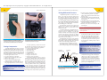
Figure 13-27.
Figure 13-28.
This optical tachometer can measure rpm without
contacting the engine by aiming it at a rotating part that
has a reflective tape attached. (Monarch Instrument)
A compression test can indicate the condition of various
mechanical components of an engine.
Testing Compression
A cylinder compression test can be a first step
toward determining the condition of the upper major
mechanical parts of the engine. This test is especially
valuable if an engine lacks power, runs poorly, and
shows little or no improvement after fuel system and
ignition adjustments. To perform a compression test:
1. Run the engine until it is warm.
2. Disconnect all drives to the engine.
3. Open the choke and throttle valves wide.
4. Remove the air cleaner.
5. Remove the spark plug and insert the
compression gauge. See Figure 13-28.
6. Crank the engine as fast as possible and read
the gauge. Repeat the test to ensure accuracy.
Note
Engines
E
ngin
ness equipped
eq
quip
pped
d with compression
com
mpression release
ccamshafts
amssha
afts ma
may
ay have to be cranked in reverse rotation
obtain
tto
o ob
btain
n an
n accurate
accu
urate reading.
readiing.
An engine producing a compression less than
the minimum specified by the manufacturer usually has one or more of the following problems:
• Leaking cylinder head gasket.
• Warped cylinder head.
• Worn piston rings.
• Worn cylinder bore.
• Damaged piston.
• Burned or warped valves.
• Improper valve clearance.
• Broken or weak valve springs.
To determine whether the valves or rings are
at fault, pour a tablespoonful of SAE 30 oil into the
spark plug hole. Crank the engine several times to
spread the oil and repeat the compression test. The
heavy oil will temporarily seal leakage at the rings.
If the compression does not improve, the leakage
is due to problems with the valves, cylinder head,
or piston. This does not disprove a problem with
the rings; the engine may have worn rings in addition to its other problems. On the other hand, if the
compression is much higher than the original test,
the leakage is due solely to defective piston rings.
257
Chapter 13 Preventive Maintenance and Troubleshooting
A differential pressure test checks the condition of an engine by measuring leakage from
the cylinder to other parts of the engine. This test
device and procedure can identify a specific worn
or damaged component in the engine that may or
may not be directly related to the cylinder condition or rings. The device is designed so that specific leakages can be detected and isolated before
disassembling parts of the engine.
The differential pressure tester requires the
application of air pressure to the cylinder being
tested with the piston at top dead center on the
compression stroke.
A schematic diagram of the differential pressure tester is shown in Figure 13-29. As the regulated air pressure is applied to one side tester
with the air shutoff valve closed, both gauges will
read the same. However, when the air shutoff
valve is opened and leakage through the cylinder
increases, the cylinder pressure gauge will record
a proportionally lower reading.
The differential pressure test can be applied to
single cylinder engines or multiple cylinder engines.
Each cylinder is tested separately and in the same
manner. Use the following procedure to test:
1. Run engine until it is warmed up to provide
uniform lubrication to cylinder walls and rings.
2. Remove the spark plug wire(s) and spark plug(s).
Regulated
pressure gauge
Air shutoff
valve
Cylinder
pressure gauge
To air
compressor
Metering
orifice
Piston at
top dead
center
3. Rotate the engine crankshaft until the piston
of the cylinder being tested is at top dead
center of the compression stroke. Both valves
must be closed.
4. Install the holding fixture supplied with the
tester to prevent the crankshaft from turning
during the test.
5. Thread the adaptor into the spark plug hole.
6. Connect the adaptor on the rubber hose to the
quick disconnect fitting on the tester.
7. Connect an air source of at least 90 psi to the
tester adaptor.
Warning
Make sure all personnel and objects are clear of the
engine shaft, belts, pulleys, or other devices connected
to the engine shaft.
8. Slowly adjust the regulated pressure gauge on
the left with the regulator knob to read 80 psi.
9. The right-hand gauge indicates the relative
pressure of the cylinder being tested. Due to
standard engine clearances and normal wear,
no cylinder is expected to maintain a perfect
80 psi. Generally, a reading of 60 psi or above
is acceptable.
Note
Itt is imp
important
porttan
nt tha
that
at all cylinders
cylin
nders on multi-cylinder
engines
e
ngin
nes
s have
hav
ve a somewhat consistent reading. Good
should
jjudgment
udgm
men
nt sho
ould be used as
as to the allowable tolerance
between
b
etw
ween
n cylinders.
cyylin
nderrs. Recheck
Rechec
ck a cylinder that has a
that
rreading
eading tha
at iss signifi
sig
gnificantlyy lower (15 psi or more) than
second
tthe
he other
othe
er cylinder(s).
cyylin
nderr(s). If a se
econd reading is still low,
tthe
he cylinder
cylin
nderr should be suspected
susp
pected of being defective.
10. By listening for the sound of escaping air, you
can determine leakage points in the engine
and the cause of the low pressure reading. A
hissing at the carburetor intake indicates a
leaking intake valve, a hissing in the exhaust
suggests a leaking exhaust valve, and hissing
from the crankcase breather indicates leaking
piston rings. See Figure 13-30.
Note
Figure 13-29.
This schematic diagram shows a differential pressure
tester connected to an engine cylinder. (Eastern
Technology Corp.)
IIff tthe
he
e test
tes
st indicates
in
ndicate
es a valve problem, first check valve
clearance
c
learrancce to m
make
akke sure the
e valve is not being held
open
o
pen
n due
du
ue to
o in
inadequate
nade
equate cle
clearance.
earance.