1
Attention: This manual is just a section from the complete Wall Oven
Service Manual. If you find that you require the complete service
manual, which includes exploded views and parts, use and care
information and installation instructions, please contact your Regional
Technical Manager.
Dacor Technical Service
Section 8 - Troubleshooting and Repair
Section 8 - Troubleshooting and Repair
Troubleshooting
Basic Troubleshooting Instructions
1. If the oven does not function properly, check for obvious problems first, such as the main power switch being
turned off, or the control panel being locked.
2. If the problem is not immediately obvious, consult the Physical Symptom Troubleshooting Guide in Appendix A.
3. If prompted by the troubleshooting guide to use the on-line diagnostics, follow the instructions below to access
the on-line diagnostics menu.
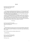
Using the On-line Diagnostics
Accessing the Diagnostics Home Screen
WARNING:
Surfaces inside the oven will become hot when certain diagnostics are running.
1
.,/
UPPER
ON/OFF
CANCEL
SECURE
START
LOWER
ON/OFF
TIMER
BACK
RECALL
S UPPER
BAKE
12:25 PM
PURE
PURE
CONV/SEAR CONVECTION
MAX
BROIL
T LOWER
7
GHI
DACOR
GUIDE
MAIN
MENU
7
PQRS
2
3
ABC
DEF
8
6
JKL
8
TUV
MNO
9
WXYZ
0
SPACE
#
x
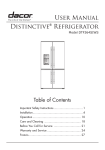
With the main power supply to the oven turned on, press and hold the CANCEL/SECURE and # keys at the
same time.
x
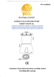
When the diagnostic password screen appears,
release the CANCEL/SECURE key (first) then the
# key.
x
Press the 7 key on the keypad repeatedly until the
letter S appears just below the words SERVICE ID
NUMBER.
x
Wait three (3) seconds.
x
Enter your service ID number. It is a minimum of
four digits long. Press ENTER.
x
The FACTORY AND SERVICE DIAGNOSTIC
HOME SCREEN appears.
x
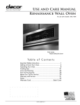
The FACTORY AND SERVICE DIAGNOSTIC
HOME SCREEN has five (5) options:
VERSION: Use this option to access
information about the software versions
programmed into the oven’s printed circuit
boards.
WARNING: ACCESS TO THE FOLLOWING SCREENS
IS LIMITED TO FACTORY AGENTS ONLY!
SERVICE ID NUMBER
S4567
EXIT
CLEAR
BACK
SPACE
ENTER
Diagnostic Password Screen
FACTORY AND SERVICE DIAGNOSTIC HOME SCREEN
SELECT AN OPERATION
EXIT
VERSION
MANUAL
DIAGNOSTIC
SERVICE
TEMP
FACTORY
TEMP
ERROR
CODES
Factory and Service Diagnostic Home Screen
Page 8-1
Dacor® Wall Oven Service Manual
MANUAL DIAGNOSTIC: Use this option to
diagnose problems with individual components
and cooking modes.
SERVICE TEMP: Use this option to modify
calibration of the various components in the
oven.
FACTORY TEMP: The base calibration settings
made at the factory. Dacor does not recommend
modifying these settings. Use the SERVICE
TEMP settings to modify the calibration of the
various cooking modes. The SERVICE TEMP
menu modifies the component calibrations based
on the FACTORY TEMP settings. If the
FACTORY TEMP settings are not tampered
with, a service technician can return the oven to
the factory settings by setting all the SERVICE
TEMP parameters to zero (0).
ERROR CODES: Use this option to view the last
twenty (20) error codes stored in the oven
controller.
FACTORY AND SERVICE DIAGNOSTIC HOME SCREEN
SELECT AN OPERATION
EXIT
VERSION
MANUAL
DIAGNOSTIC
SERVICE
TEMP
FACTORY
TEMP
ERROR
CODES
Factory and Service Diagnostic Home Screen
See the appropriate section on the following pages for a detailed description on how to use the above diagnostic
screens.
When done with the diagnostic screens, press CANCEL/SECURE, to return to the home screen.
Version Screen
Overview
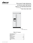
x
The center column contains information about the
software loaded into the oven controller (LOGIC
VERSION).
x
The left-hand column contains information about the
software loaded into the relay board of a single oven
or the upper relay board of a double oven.
x
The right-hand column contains information about
the software loaded into the relay board of the lower
relay board of a double oven.
IMPORTANT:
S UPPER
[1] U10 1001
[2] U10 EE BD
[3] U7 1001
[4] U7 EE 5D
LOGIC VERSION
1.0.0.2-D 27
USER CS: FEE14E45
U CS: 0
L CS: 0
T LOWER
[1] U10 1001
[2] U10 EE BD
[3] U7 1001
[4] U7 EE 5D
Version Screen
The versions and checksums for
the upper and lower relay
boards on a double oven must
match for the oven to work
properly.
Oven Controller Software (Center Column)
The logic (software) version of the oven controller
software is located in the second row of the center
column.
A
S UPPER
[1] U10 1001
A
[2] U10 EE BD
[3] U7 1001
[4] U7 EE 5D
LOGIC VERSION
1.0.0.2-D 27
USER CS: FEE14E45
U CS: 0
L CS: 0
T LOWER
[1] U10 1001
[2] U10 EE BD
[3] U7 1001
[4] U7 EE 5D
This information below the LOGIC VERSION has no
useful purpose for service.
Version Screen
Page 8-2
Section 8 - Troubleshooting and Repair
Single/Upper Relay Board Software (Left Column)
[1] The version of the software programmed into the
flash memory in processor U10 on the single/upper relay
board.
B
S UPPER
[1] U10 1001
[2] U10 EE BD
[3] U7 1001
[4] U7 EE 5D
[2] The checksum value of the software programmed
into the EEPROM memory in processor U10 on the
single/upper relay board.
[3] The version of the software programmed into the
flash memory in processor U7 on the (double) lower
relay board.
LOGIC VERSION
1.0.0.2-D 27
USER CS: FEE14E45
B0
U CS:
L CS: 0
T LOWER
[1] U10 1001
[2] U10 EE BD
[3] U7 1001
[4] U7 EE 5D
C
Version Screen
[4] The checksum value of the software programmed
into the EEPROM memory in processor U7 on the
(double) lower relay board.
Lower Relay Board Software (Right Column)
C
[1] The version of the software programmed into the
flash memory in processor U10 on the single/upper relay
board.
[2] The checksum value of the software programmed
into the EEPROM memory in processor U10 on the
single/upper relay board.
[3] The version of the software programmed into the
flash memory in processor U7 on the (double) lower
relay board.
[4] The checksum value of the software programmed
into the EEPROM memory in processor U7 on the
(double) lower relay board.
Page 8-3
Dacor® Wall Oven Service Manual
Manual Diagnostic Screen
The diagnostic screen offers four (4) options for
exercising the oven components in a manner that will
allow diagnosis of various types of failures:
MANUAL DIAGNOSTICS ALLOW SERVICER TO EXERCISE OVEN COMPONENTS
AND COOKING MODES INDIVIDUALLY WHILE MONITORING FEEDBACK OF
INPUTS AND BY VISUAL INSPECTION.
SELECT OUTPUTS, MODES 1, OR 2; PRESS NUMBER TO TURN ITEM ON.
CHANGE TO INPUTS SCREEN TO VIEW CONSTANT FEEDBACK.
EXIT
x
Outputs
x
Inputs
x
Modes 1
x
Modes 2
OUTPUTS
INPUTS
MODES 1
MODES 2
Manual Diagnostic Home Screen
See the following pages for a detailed description of
each option.
Outputs
This diagnostic mode allows the service technician to
turn each output component in the oven on by itself
while leaving all other output components off. To turn
one of the output components on:
x
Press the OUTPUTS key.
x
If servicing a double oven, select the upper or lower
oven (press UPPER ON/OFF or LOWER ON/OFF)
when prompted to do so.
x
The OUTPUTS diagnostic screen will appear.
x
To turn on a particular component, press the
appropriate number on the keypad. The display will
indicate the component that has been turned on.
Check to make sure the appropriate component is
functioning normally. Only one (1) output
component may be turned on at a time.
x
S UPPER
T LOWER
SELECT UPPER OR LOWER OVEN.
Press UPPER ON/OFF or LOWER ON/OFF
[1] BAKE INNER OFF
[2] BAKE OUTER OFF
[3] BROIL INNER OFF
[4] BROIL OUTER OFF
[5] CONVECT ELEMENT OFF
EXIT
OUTPUTS
INPUTS
[6] COOL FAN HI OFF
[7] COOL FAN LO OFF
[8] CONVECT FAN HI OFF
[9] CONVECT FAN LO OFF
[0] LATCH MOTOR OFF
MODES 1
MODES 2
Outputs Diagnostic Screen
To turn off an output component that is on, press
the appropriate number on the keypad.
Inputs
This diagnostic screen allows the service technician to
monitor all of the input components while stimulus is
applied.
[1] PROBE #1 A/D 98 0
[2] PROBE #1 A/D 8B 0
[3] PROBE #1 A/D 8F 0
[4] PROBE #1 A/D 199 CC
[5] MEAT PROBE A/D 0
EXIT
OUTPUTS
[6] HALL EFFECT SENSOR 0
[7] CAM SWITCH STATE CLOSED
[8] LOCK SWITCH STATE OPEN
[9] DOOR SWITCH STATE CLOSED
INPUTS
MODES 1
MODES 2
Inputs Diagnostic Screen
Page 8-4
Section 8 - Troubleshooting and Repair
Temperature Sensor
x
A hexadecimal number appears after each of the
temperature sensor entries. These numbers
represent the temperature detected by the sensor.
To determine if the temperature sensors are
working correctly:
[1] PROBE #1 A/D 98 0
[2] PROBE #1 A/D 8B 0
[3] PROBE #1 A/D 8F 0
[4] PROBE #1 A/D 199 CC
[5] MEAT PROBE A/D 0
EXIT
OUTPUTS
[6] HALL EFFECT SENSOR 0
[7] CAM SWITCH STATE CLOSED
[8] LOCK SWITCH STATE OPEN
[9] DOOR SWITCH STATE CLOSED
INPUTS
MODES 1
MODES 2
Close the oven door.
From the OUTPUTS screen, turn on the bake
element.
Press the INPUTS key. The hexadecimal
numbers after the probe 1, 2, and 3 entries on
the display should change in value to indicate a
rise in temperature. Probe #4 is not used.
Inputs Diagnostic Screen
Turn off the bake element.
Wiring Diagram Call-Out
Location
RTD1 (Probe #1)
RTD2 (Probe #2)
RTD3 (Probe #3)
(Probe #4)
Center Right
Center Left
Upper Right
Not Used
Table 8-1 Temperature Sensor Locations
Meat Probe
x
A hexadecimal number appears after the meat probe
entry on the display. The number represents the
temperature detected. To determine if the meat
probe is working correctly:
Plug the meat probe into the meat probe socket
and suspend it from one of the rack supports.
From the OUTPUTS screen, turn on the bake
element.
Press the INPUTS key. The hexadecimal
numbers after the MEAT PROBE entry on the
display should change in value to indicate a rise
in temperature.
Turn off the bake element.
Hall Effect Sensor (Cooling Fan Tachometer)
x
A number appears after the hall effect sensor entry
on the INPUTS screen. It is a read out of the
cooling fan speed. To determine if the cooling fan is
operating at the proper speed and that the hall
effect sensor is working:
From the OUTPUTS screen, turn on the cooling
fan at the LO setting.
Press the INPUTS key.
Take note of the number after the hall effect
sensor entry on the INPUTS screen.
Go to the OUTPUTS screen and change the
cooling fan speed to HI.
Page 8-5
Dacor® Wall Oven Service Manual
Press the INPUTS key.
The hall effect sensor reading should be at least
50 units higher than when the fan is on LO.
Cam and Lock Switches
The oven controller uses the cam and lock switches to
determine the position of the door latch during the selfclean process. To test the cam and lock switches:
Open the oven door.
[1] PROBE #1 A/D 98 0
[2] PROBE #1 A/D 8B 0
[3] PROBE #1 A/D 8F 0
[4] PROBE #1 A/D 199 CC
[5] MEAT PROBE A/D 0
EXIT
OUTPUTS
[6] HALL EFFECT SENSOR 0
[7] CAM SWITCH STATE CLOSED
[8] LOCK SWITCH STATE OPEN
[9] DOOR SWITCH STATE CLOSED
INPUTS
MODES 1
MODES 2
From the OUTPUTS screen, select the latch
motor.
Go to the INPUTS screen. Observe the door
latch while monitoring the cam or lock switch
entries.
Inputs Diagnostic Screen
The cam switch should be closed only when the
door latch is completely retracted.
The lock switch should be closed only when the
door latch is in the latched position.
Turn off the latch motor when the latch is
completely retracted.
WARNING:
Do not close the oven door
unless the door latch is
completely retracted.
Modes (1 and 2)
This diagnostic mode allows the service technician to set
the oven to a cooking mode without having to exit the
diagnostics to the home screen. To turn on one of the
oven cooking modes from the FACTORY AND
SERVICE DIAGNOSTICS HOME SCREEN:
x
Press the MODE 1 or MODE 2 key.
x
If servicing a double oven, select the upper or lower
oven.
x
The MODE diagnostics screen will appear. If the
desired oven mode does not appear on the display,
press the other mode key.
NOTE:
FRUITS OFF, VEGGIES OFF,
and MEATS OFF refer to the
three (3) dehydrate modes.
x
Press the appropriate number on the keypad to
select the desired mode of operation.
x
Check the oven operation according to the cycling
chart in Appendix C or the INPUTS screen.
x
To turn off the oven cooking mode, press the
appropriate number on the keypad.
Page 8-6
[1] BAKE OFF
[2] PURE CONVECTION OFF
[3] SURROUND BAKE OFF
[4] CONVECTION BAKE OFF
[5] SURR CONVECTION BAKE OFF
EXIT
OUTPUTS
INPUTS
[6] PURE CONV/SEAR OFF
[7] PURE CONVECTION OFF
[8] SURROUND ROAST OFF
[9] CONVECTION ROAST OFF
[0] SURR CONVECTION ROAST OFF
MODES 1
MODES 2
MODES 1 Diagnostic Screen
[1] BROIL OFF
[2] MAX BROIL OFF
[3] CONVECTION BROIL OFF
[4] DEFROST OFF
[5] PROOF OFF
EXIT
OUTPUTS
INPUTS
[6] FRUITS OFF
[7] VEGGIES OFF
[8] MEATS OFF
MODES 1
MODES 2
MODES 2 Diagnostic Screen
Section 8 - Troubleshooting and Repair
Service Temp Screen
The service temp screen allows the service technician to modify the calibration of the various oven cooking modes.
The settings on the SERVICE TEMP screen indicate the amount by which the factory calibration settings (see the
FACTORY TEMP screen) are raised or lowered. If the FACTORY TEMP calibration settings are not tampered with, a
service technician can return the oven to the factory settings by changing all the SERVICE TEMP settings back to
zero.
To set the SERVICE TEMP settings:
x
From the FACTORY AND SERVICE DIAGNOSTIC
HOME SCREEN, press the SERVICE TEMP key.
x
If a double oven is being serviced, select the upper
or lower oven (press UPPER ON/OFF or LOWER
ON/OFF) when prompted to do so.
x
A warning screen will appear. Press OK.
x
The SERVICE TEMP screen will appear. Additional
cooking mode settings can be viewed by pressing
the NEXT key.
Two (2) temperature settings appear at the end of each
cooking mode entry. For example [1] BAKE +10/+20.
The first number is the previous SERVICE TEMP
setting. The second number is the current SERVICE
TEMP setting. The current temperature setting becomes
the previous temperature setting when a new
temperature setting is entered. Press the RESET key, to
return all the current settings to the values of the
previous settings.
WARNING: CHANGES IN THIS AREA ARE IN ADDITION TO FACTORY CAL.
SETTINGS UNDER THE FACTORY TEMP CALIBRATION SCREEN.
USE THIS AREA TO DO FIELD ADJUSTMENTS TO FINE TUNE OVEN.
SELECT OK TO RETURN TO THE EDIT SCREEN.
SET SERVICE OFFSETS TO +0 TO RETRUN TO FACTORY DEFAULT.
PRESS OK TO CONTINUE
OK
SERVCE TEMP Warning Screen
[1] BAKE +0/+0
[2] PCONV BAKE +0/+0
[3] SURR BAKE +0/+0
[4] CONV BAKE +0/+0
[5] SCONV BAKE +0/+0
OK
+5qF
[6] PCONV/SEAR +0/+0
[7] PCONV ROAST +0/+0
[8] SURR ROAST +0/+0
[9] CONV ROAST +0/+0
[0] SCONV ROAST +0/+0
-5qF
RESET
NEXT
SERVICE TEMP Screen
To change the current setting for a particular mode:
x
Press mode number on the keypad.
x
Press the +5qF or -5qF keys repeatedly until the
desired temperature shift appears on the display.
The setting can be varied by up to +/- 35qF.
x
To make changes to additional cooking modes, press
the appropriate number on the keypad and enter the
temperature change in the same manner.
x
Press OK when done changing the temperature
settings. The temperature values entered will offset
the values in the FACTORY TEMP menu.
Factory Temp Screen
These are the base calibration settings made at the
factory. Dacor does not recommend modifying these
settings. If the FACTORY TEMP settings must be
changed, they are changed in the same manner as the
SERVICE TEMP settings.
Page 8-7
Dacor® Wall Oven Service Manual
Error Codes Screen
The ERROR CODES screen displays the twenty (20)
most recent error codes stored in the oven controller. To
access the ERROR CODES screen:
x
From the FACTORY AND SERVICE DIAGNOSTIC
HOME SCREEN, press the ERROR CODES key.
The most recent error code will appear in the number
[1] position on the display. When a new error code is
written to the oven controller, the new error code will
appear in the number [1] position.
Page 8-8
[1] U32 TEMP SENSOR
[2] U50 LATCH/DOOR
[3] U61 COOLING FAN
[4] NO ERRORS
[5] NO ERRORS
EXIT
[6] NO ERRORS
[7] NO ERRORS
[8] NO ERRORS
[9] NO ERRORS
[0] NO ERRORS
CLEAR ALL
ERROR CODES Screen
Section 8 - Troubleshooting and Repair
Component Access and Disassembly
WARNING:
Turn off the electrical power supply to the appliance prior to servicing it. Failure to disconnect
the power supply during service may result in an electrical shock or fire hazard.
Door Removal
WARNING:
On double ovens: Remove the lower door first. Otherwise, damage to the top of the lower
door may occur when the upper door is removed.
WARNING:
Do not attempt to disengage the hinge locks on the door while it is removed from the oven.
The hinge springs could release, causing personal injury.
WARNING:
Do not lift or carry the oven door by the door handle.
x
Open the oven door completely.
x
Pull the hinge locks forward on both hinges, until they
stop.
Hinge Lock
x
Raise the door so that it is at a 15° angle from the
front of the oven. Hold the door with one hand on
each side. Lift the door up and out.
See page 8-20 for door disassembly and repair
instructions.
Door Removal
Page 8-9
Dacor® Wall Oven Service Manual
Door Installation
WARNING:
Be sure that the notch on the bottom of each hinge rests on top of the lower lip of EACH
hinge receptacle before attempting to open the oven door. Failure to do so may cause the
door to fall off its hinges, resulting in personal injury or damage to the door.
WARNING:
Rotate the hinge locks toward front of the oven immediately after installation of the door.
Failure to do so may cause the door to fall off its hinges, resulting in personal injury or
damage to the door.
WARNING:
On double ovens: Install the upper door first. Otherwise, damage to the top of the lower
door may occur.
x
Grasp the oven door on opposite sides and hold it at a
15q angle from the front of the oven. Slide the hinges
A into the hinge openings B , resting the bottom of
the hinge arms C on the lower lip D of the hinge
receptacles. Continue to hold the door at a 15q angle with
one hand while pushing in on the each of the bottom
corners of the door. Push until the notch E on the
bottom of each hinge slips over the lower lip D of each
hinge receptacle.
x
Lower the door to the fully opened position.
x
Rotate the two hinge locks toward the oven.
x
Open and close the door completely to ensure that it is
properly installed.
x
Remove any protective plastic from the front of the oven
and any packaging from inside the oven.
Door Installation
B
A
E
D
C
Hinge
Hinge Opening and Receptacle
Page 8-10
Section 8 - Troubleshooting and Repair
Removing the Oven from the Wall
x
x
WARNING:
Use an appliance dolly to move the appliance when installing it or removing it from the wall
for service. Use of an appliance dolly will minimize the risk of personal injury as a result of
the oven tipping.
WARNING:
Hold the oven steady when removing it from the wall. Otherwise, the oven will have a
tendency to tip forward, increasing the risk of personal injury.
WARNING:
Do not use the door or the door handles to lift, carry, or move the oven. Personal injury may
result.
NOTE:
Not all service procedures require that the oven be removed from the wall. See the
appropriate procedure to determine if removal from the wall is necessary.
Remove the oven door(s) as described on page 8-9.
Due to the weight of this appliance, removing the
door(s) will significantly reduce the lifting load.
Removing the door(s) will also providing the
technician with a place to grip the oven when
removing it from the wall.
F
F
Remove the mounting screws that hold the oven in
place. The screws are located inside the door jams of
oven on the trim posts on both sides of the oven.
There are two possible locations F for the mounting
screws on the trim post G : facing the front of the
oven or facing in toward the oven chamber. Single
ovens are held in place by four (4) screws. Double
ovens are held in place by six (6) screws.
G
Oven Mounting Screw Locations
x
Remove the oven racks from the oven.
x
Pull the oven out of the wall toward you, using the
gripping points and side handles. Hold it steady as you
pull. Some service procedures only require that you
pull the oven out the few inches. Other service
procedures require that the oven be pulled completely
out of the wall. See the appropriate part replacement
procedure to determine how far to remove the oven
from the wall.
x
Gripping Point
To reinstall the oven, see the installation procedure on
page 3-13.
Handle
Gripping Point
Gripping Point
Gripping Points
Page 8-11
Dacor® Wall Oven Service Manual
Oven Chamber Components
Smoke Eliminator
WARNING:
NOTE:
Turn off the electrical power supply to the appliance prior to servicing it. Failure to disconnect
the power supply during service may result in an electrical shock or fire hazard.
Each oven chamber is equipped with two smoke eliminators. One is accessible from inside
the oven chamber, the other is located inside the chassis directly above the one inside the
oven chamber*. The smoke eliminator(s) located inside the oven chamber(s) can be replaced
without removing the oven from the wall. The chassis smoke eliminator(s) require that the
oven be removed from the wall to be replaced.
* There is one exception. There is no chassis smoke eliminator for the upper chamber of a
double oven.
x
Remove the oven door(s) as described on page 8-9.
x
Remove the oven racks from the oven chamber.
x
The oven chamber smoke eliminator A is located on
the ceiling of the oven chamber behind the broil
element, above the convection fan B .
x
Remove the three (3) screws that hold the smoke
eliminator in place. Be careful not to scratch the back
of the oven with the screwdriver during removal and
installation.
x
To install the smoke eliminator, fasten it in place with
the three (3) existing screws.
x
A
B
Reinstall the oven door(s) as described on page 8-10.
Smoke Eliminator on Oven Ceiling
Page 8-12
Section 8 - Troubleshooting and Repair
Convection Element and Fan
WARNING:
Turn off the electrical power supply to the appliance prior to servicing it. Failure to disconnect
the power supply during service may result in an electrical shock or fire hazard.
Convection Baffle Removal
x
Remove the oven door(s) as described on page 8-9.
x
Remove the oven racks from the oven chamber.
x
Remove the convection filter by lifting it up and out.
x
Remove the four (4) screws that hold the convection
baffle in place. The screws are located near the four
corners of the baffle at the back of the oven.
x
Remove the convection baffle.
Convection Baffle Screw Locations
Convection Element Disassembly
x
Remove the three (3) screws holding the convection
element in place.
Convection Element Screw Locations
x
Grasp the convection element at the base and pull it
out slowly with a gentle, rocking motion. Do not pull
the convection element out too quickly because the
wires that connect to the element could pull free
inside the oven wall.
x
Disconnect the wires from the terminals of the
element and remove it from the oven.
x
To replace the convection element:
Place the convection element in the oven and
attach the wires to the terminals.
Grasp the convection element at the base and
push it slowly back into place with a gentle
rocking motion.
Replace the three (3) mounting screws that hold
Convection Element Removal
Page 8-13
Dacor® Wall Oven Service Manual
the convection element in place.
Convection Fan Removal
x
To remove the convection fan, hold it with one hand
and turn the nut clockwise with a wrench.
x
When replacing the fan, make sure that the washer is
installed behind the fan blade before replacing the fan.
Use a wrench to tighten the nut counterclockwise.
Convection Fan Nut Removal
Convection Baffle Installation
x
Install the convection baffle against the back wall of
the oven with the large square hole C located on the
bottom left.
x
Replace the four (4) mounting screws that hold the
baffle in place.
x
Replace the convection filter.
x
Reinstall the oven door(s) as described on page 8-10.
x
Test the oven to ensure that repairs were properly
completed.
C
Convection Baffle Orientation
Page 8-14
Section 8 - Troubleshooting and Repair
Bake Element Assembly Removal
WARNING:
Turn off the electrical power supply to the appliance prior to servicing it. Failure to disconnect
the power supply during service may result in an electrical shock or fire hazard.
IMPORTANT:
The bake element wires must be properly labeled so that they can be connected to the same
terminal when the element is replaced. If the wires are not properly connected, the oven will
not function properly.
IMPORTANT:
When removing it from the oven, do not hold the bake element assembly by the wires.
Damage to the bake element terminals may result.
IMPORTANT:
Exercise caution when handling the bake element when it is removed from the oven. The
insulation around the edge of the bake element is fragile and can be damaged easily.
x
Remove the oven door(s) as described on page 8-9.
x
Remove the oven racks from the oven chamber.
x
Remove the eight (8) screws that hold the bake
element frame D in place on the floor of the oven.
x
Remove the bake element frame and glass
D
E.
E
Bake Element Components
x
If replacing the bake element F , pull it up and out of
the floor of the oven. Label the wires that connect to
the bake element terminals G . When reconnecting the
wires, make sure that the wires are connected to the
proper terminal.
x
If replacing the bake element glass, make sure that
the smooth side of the glass is facing up when placing
it in the oven.
x
When reassembling the bake element in the floor of
the oven, place the bake element glass inside the bake
element frame and place it over the top of the bake
element in the floor of the oven.
x
Hold the bake element frame in place with one hand
while replacing the eight (8) existing screws that hold
it in place.
x
Reinstall the oven door(s) as described on page 8-10.
x
Test the oven to ensure that repairs were properly
completed.
G
F
Bake Element Removal
Page 8-15
Dacor® Wall Oven Service Manual
Broil Element Assembly Removal
WARNING:
Turn off the electrical power supply to the appliance prior to servicing it. Failure to disconnect
the power supply during service may result in an electrical shock or fire hazard.
IMPORTANT:
The broil element wires must be properly labeled so that they can be connected to the same
terminal when the element is replaced. If the wires are not properly connected, the oven will
not function properly.
IMPORTANT:
When removing it from the oven, do not hold the broil element assembly by the wires.
Damage to the broil element terminals may result.
IMPORTANT:
Exercise caution when handling the broil element when the broil element assembly is
disassembled. The insulation around the edges of the broil element is fragile and can be
damaged easily.
x
Remove the oven door(s) as described on page 8-9.
x
Remove the oven racks from the oven chamber.
x
Holding the broil element assembly in place with one
hand, remove the eight (8) screws that hold it in place.
x
Gently lower the broil element out of the ceiling of the
oven chamber.
Broil Element Removal
x
Label the wires that connect to the broil element.
x
Gently remove the broil element wires from the
terminal block on the broil element assembly.
Broil Element Terminal Block
Page 8-16
Section 8 - Troubleshooting and Repair
x
Place the broil element assembly on a flat, padded
surface and remove the screws from each of the four
(4) corners.
Broil Element Disassembly
K
x
The broil element assembly separates into three (3)
components, the broil element H , the broil element
frame D , and the broil element glass J .
x
To reassemble the broil element assembly, use the
four (4) existing screws. The smooth side of the broil
element glass should face away from the broil
element. During reassembly, make sure that the broil
element terminals K and the smoke eliminator cutout
L are on the same side.
x
Place the broil element into the oven chamber with
the glass facing down and the terminals toward the
back of the oven.
H
J
D
L
Broil Element Components
x
Lift the back of the element up and reconnect the broil
element wires to the terminals on the broil element
assembly. Make sure that the wires are connected to
the proper terminals.
x
Insert the broil element assembly into the hole in the
oven ceiling while pushing the broil element wires into
the access hole toward the back.
x
Hold the broil element assembly in place with one
hand while replacing the eight (8) existing screws that
hold it in place.
x
Reinstall the oven door(s) as described on page 8-10.
x
Test the oven to ensure that repairs were properly
completed.
Connecting the Broil Element Wires
Page 8-17
Dacor® Wall Oven Service Manual
Temperature Sensor Removal
WARNING:
Turn off the electrical power supply to the appliance prior to servicing it. Failure to disconnect
the power supply during service may result in an electrical shock or fire hazard.
x
Remove the oven door(s) as described on page 8-9.
x
Remove the oven racks from the oven chamber.
Rack Support Removal
x
Remove the four (4) screws that hold the rack support
(on the appropriate side) in place. Be careful not to
scratch the inside surface of the oven when removing
it.
Rack Support Screw Removal
Temperature sensor removal
x
Remove the two (2) screws that hold the temperature
sensor M in place.
x
When removing the temperature sensor, pull the wires
attached to the sensor gently toward you through the
hole in the back of the oven to expose the connector.
Do not pull hard on the wires because the connector
may come loose inside the oven wall. Use a
screwdriver, if necessary, to move the insulation
around behind the hole to allow the connector to slide
out into the oven chamber.
Wiring Diagram Call-Out
Location
RTD1
RTD2
RTD3
Center Right
Center Left
Upper Right
M
Temperature Sensor (1 of 3 Inside Oven)
Table 8-2 Temperature Sensor Locations
x
Disconnect the temperature sensor wires at the
connector N and remove the temperature sensor.
x
When reinstalling the temperature sensor, gently push
the connector and excess wire through the access hole
and insulation at the back of the oven.
x
Tighten the temperature sensor into place with the
two (2) existing mounting screws.
N
Temperature Sensor Connector
Page 8-18
Section 8 - Troubleshooting and Repair
Rack Support Installation
IMPORTANT:
x
x
To prevent scratching of the oven and wall, replace the rack support only in the manner
specified below.
Insert the end of the rack support with the two (2)
vertical bars O first. Insert the rack support into the
oven at a 45° angle to the sidewall, placing the two
vertical bars behind the temperature sensor P .
Rotate the rack support into place, matching the four
(4) protruding pins Q on the rack support to the holes
R in the oven wall.
x
Mount the rack support in place using the four (4)
existing screws.
x
Reinstall the oven door(s) as described on page 8-10.
x
Test the oven to ensure that repairs were properly
completed.
Q
R
O
P
R
Rack Support Installation
Page 8-19
Dacor® Wall Oven Service Manual
Door Components
Door Gasket (seal)
x
Remove the oven door(s) as described on page 8-9.
x
Lay the door on a flat, padded surface with the door
gasket A facing up.
x
Remove the gasket by grasping sections of it and
pulling up.
x
Insert the self-locking tabs on the replacement gasket
into the holes on the oven door. Check to make sure
that all of the self-locking tabs are firmly in place by
pulling gently on the gasket.
x
Reinstall the oven door(s) as described on page 8-10.
A
Door Gasket Location
Door Handle
x
Remove the oven door(s) as described on page 8-9.
x
Lay the door on a flat, padded surface with the door
gasket facing up.
x
Remove the two (2) screws
the door.
x
Grasp the door with one hand and pull up. Pull the
door handle out from underneath.
x
To reinstall the door handle, grasp the door with one
hand and pull up. Hold the handle in position on the
front. Lower the door onto the padded surface.
x
Replace the two (2) screws in the top corners of the
door and tighten into place. Do not over-tighten the
screws, because the front door glass could crack.
x
Reinstall the oven door(s) as described on page 8-10.
Page 8-20
B
B
B
in the top corners of
Door Handle Screw Locations
Section 8 - Troubleshooting and Repair
Front Door Glass Assembly
WARNING: To prevent personal injury, use gloves
when handling glass components that
are broken or shattered.
x
Remove the oven door(s) as described on page 8-9.
x
Lay the door on a flat, padded surface with the door
gasket facing up.
x
Remove the two (2) screws B in the top corners of
the door and the two (2) inner screws C on the
bottom of the door.
B
B
NOTE: The outer screws D on the bottom of the
door are part of the hinge assembly.
C
C
D
x
x
Oven Door Screws Locations
Holding the door tightly with both hands, turn it over
and place it on the flat, padded surface with the front
door glass facing up. Be careful to hold the door
assembly tightly while turning it over, since the screws
that hold it together have been removed.
x
Grab the front door glass assembly with both hands
and remove it.
x
If the silicone door gaskets E require replacement,
replace them while the front door glass is removed.
x
Make sure that the door spacers F in the top corners
of the door are still in place before putting the front
door glass back into in place.
x
D
Grasp the top end of the door with one hand and pull
up. Pull the door handle out from underneath.
When replacing the front door glass assembly G , the
tabs on the bottom should rest inside of the tabs on
the door liner H .
x
Holding the door tightly with both hands, turn it over
and place it on the flat, padded surface with the door
gasket facing up.
x
To reinstall the door handle, grasp the top end of the
door with one hand and pull up. Hold the handle in
position on the front. Lower the door onto the padded
surface.
x
Replace the four (4) screws in the top corners and
bottom and of the door and tighten into place. Do not
over-tighten the screws because the door glass could
crack.
x
Reinstall the oven door(s) as described on page 8-10.
F
F
E
E
E
Door Gasket and Spacer Locations
G
E
H
Front Door Glass and Handle Reassembly
Page 8-21
Dacor® Wall Oven Service Manual
Door Switch Magnet and Hinges
x
Remove the oven door(s) as described on page 8-9.
x
Lay the door on a flat, padded surface with the door
gasket facing up.
x
Remove the two (2) screws B in the top corners of
the door and the two (2) inner screws C on the
bottom of the door.
B
B
NOTE: The two outer screws D on the bottom of
the door are part of the hinge assembly.
x
x
Grasp the top end of the door with one hand and pull
up. Pull the door handle out from underneath.
Holding the door tightly with both hands, turn it over
and place it on the flat, padded surface with the front
door glass facing up. Be careful to hold the door
assembly tightly while turning it over, since the screws
that hold it together have been removed.
x
Grab the front door glass assembly with both hands
and remove it.
x
If you are replacing the door magnet I (located in the
top right corner below the door spacer F ), use a
screwdriver to break the plastic tabs on the side of the
magnet that hold it in place. Push the old door magnet
assembly out through the back of the door assembly.
Insert the replacement door magnet into the door
magnet mounting hole and push it in until it locks
firmly into place.
C
C
D
D
Oven Door Screw Locations
F
I
I
B
Door Magnet and Door Spacer
x
If you are replacing one of the hinges, remove the
three (3) screws J that hold the hinge cover
plate K and the hinge L in place.
J
K
J
L
J
Door Hinge Screw Locations
Page 8-22
Section 8 - Troubleshooting and Repair
x
With the hinge cover plate removed, pry up the hinge
L with a screwdriver. Insert the replacement hinge
into place and install using the two (2) existing screws
that hold it in place. Replace the hinge cover plate and
the three (3) existing screws that hold it in place.
E
L
Hinge Removal
x
Make sure that the door spacers F in the top corners
of the door are in place before replacing the front door
glass assembly.
F
F
Door Spacer Placement
x
When replacing the front door glass assembly G , the
tabs on the bottom should rest inside of the tabs on
the door liner H .
x
Holding the door tightly with both hands, turn it over
and place it on the padded surface with the door
gasket facing up.
x
To reinstall the door handle, grasp the top end of the
door with one hand and pull up. Hold the handle in
position on the front. Lower the door onto the padded
surface.
x
Replace the four (4) screws in the top corners and
bottom and of the door and tighten into place. Do not
over-tighten the screws, because the door glass could
crack.
x
Reinstall the oven door(s) as described on page 8-10.
G
H
E
Front Door Glass Reassembly
Page 8-23
Dacor® Wall Oven Service Manual
Inner Door and Window Assembly
WARNING: To prevent personal injury, use gloves
when handling glass components that
are broken or shattered.
x
Remove the oven door(s) as described on page 8-9.
x
Lay the door on a flat, padded surface with the door
gasket facing up.
x
Remove the two (2) screws B in the top corners of
the door and the two (2) inner screws C on the
bottom of the door.
NOTE: The two outer screws D on the bottom of
the door are part of the hinge assembly.
B
B
C
C
D
D
Oven Door Screw Locations
x
x
Grasp the top end of the door with one hand and pull
up. Pull the door handle out from underneath.
Holding the door tightly with both hands, turn it over
and place it on the flat, padded surface with the front
door glass facing up. Be careful to hold the door
assembly tightly while turning it over, since the screws
that hold it together have been removed.
x
Grab the front door glass with both hands and remove
it.
x
Remove the six (6) screws N that hold the inner heat
shield O in place. Lift the outer heat shield up and out
towards the top of the door. Take care not to damage
the door magnet I .
I
O
N
N
N
N
Inner Heat Shield Screw Locations
x
Remove the three (3) screws P that hold the lower
outer heat shield in place. Lift the lower outer heat
shield up and out towards the top of the door.
x
Remove the five (5) remaining screws Q that hold the
upper outer heat shield in place. Lift up and remove
the upper outer heat shield toward the top of the
door. Take care not to damage the door magnet.
Q
Q
Q
Q
Q
P
P
P
Lower Outer and Outer Heat Shield
Screw Locations
Page 8-24
Section 8 - Troubleshooting and Repair
x
Push the glass window assembly out of the door liner
from the bottom and lift it out.
x
Replace the window glass assembly. The seam R in
the metal rim around the glass must be put toward
the top of the door.
x
Replace the upper outer heat shield and tighten into
place using the five (5) existing screws.
x
Replace the lower outer heat shield and tighten into
place using the three (3) existing screws.
x
Replace the inner heat shield and tighten into place
using the six (6) existing screws.
R
Inner Door Glass Assembly Removal
x
Make sure that the door spacers F in the top corners
of the door are in place before putting the
replacement door glass in place.
F
F
Door Spacer Placement
x
When replacing the front door glass assembly G , the
tabs on the bottom should rest inside of the tabs on
the door liner H .
x
Holding the door tightly with both hands, turn it over
and place it on the flat, padded surface with the door
gasket facing up.
x
To reinstall the door handle, grasp the top end of the
door with one hand and pull up. Hold the handle in
position on the front. Lower the door onto the padded
surface.
x
Replace the four (4) screws in the top corners and
bottom and of the door and tighten into place. Do not
over-tighten the screws, because the door glass could
crack.
x
Reinstall the oven door(s) as described on page 8-10.
G
H
Front Door Glass Reassembly
Page 8-25
Dacor® Wall Oven Service Manual
Control Panel
WARNING: Turn off the electrical power supply to the appliance prior to servicing it. Failure to disconnect the
power supply during service may result in an electrical shock or fire hazard.
WARNING: The control panel, power supply, and relay board assemblies in this oven contain electronic
components that are sensitive to electrostatic discharge (ESD). Wear a properly grounded
antistatic wrist strap when handling or servicing the printed circuit assemblies. Insert the ESD
sensitive circuit boards into antistatic bags before placing them on any surface other than the
oven chassis.
x
Remove the oven from the wall as specified on page
8-10.
x
Remove the four (4) screws from the top of the oven
immediately in back the control panel.
Screws on Top of Control Panel
x
Remove the six (6) screws from the bottom of the
control panel.
Screws on Bottom of Control Panel
x
Grab the sides of control panel with both hands and
pull it forward with a gentle rocking motion until it
comes loose from the front of the oven.
Control Panel Removal
Page 8-26
Section 8 - Troubleshooting and Repair
x
x
Disconnect the wires A from the back of the control
panel printed circuit board assembly.
A
When replacing the control panel, connect the wires
from the oven to the printed circuit board assembly
on the back of the control panel. Match the location
marked to on the connectors to the locations marked
on the printed circuit board. Single ovens have two
(2) connections, while double oven models have three
(3).
U
A
Control Panel Wiring
Oven Controller Removal
x
Remove the four (4) screws
controller C in place.
B
that hold the oven
B
B
B
B
C
Oven Controller Screw Locations
x
Remove both of the display flex connectors from the
two (2) sockets on the back of the oven controller
board.
x
Pull the oven controller off the back of the LED board
with a gentle rocking motion.
Display Flex Connections
Page 8-27
Dacor® Wall Oven Service Manual
LED Board Removal
x
Remove the four (4) screws that hold the LED board
on the back of the touch panel.
x
Remove the LED board from the back of the touch
panel.
LED Board Screw Locations
LCD Display Removal
The LCD display is mounted to the back of the LED board.
x
Pull out gently on the display while prying the six (6)
display retention clips loose on the other side of the
LED board.
Display Retention Clip Locations
x
Remove the display from the back of the LED board.
To reinstall the control panel:
x
Reassemble the control panel in the reverse order.
x
Install the control panel in its original position and
replace the ten (10) screws that hold it in place.
x
Reinstall the oven door(s) as described on page 8-10.
x
Test the oven to ensure that repairs were properly
completed.
x
Reinstall the oven as shown in the installation section
of this manual (see page 3-13).
LCD Display Removal
Page 8-28
Section 8 - Troubleshooting and Repair
Components Behind the Control Panel
WARNING:
Turn off the electrical power supply to the appliance prior to servicing it. Failure to disconnect
the power supply during service may result in an electrical shock or fire hazard.
Power Supply and Relay Boards
WARNING:
The control panel, power supply, and relay board assemblies in this wall oven contain
electronic components that are sensitive to electrostatic discharge or ESD. Wear a properly
grounded antistatic wrist strap when handling or servicing the printed circuit assemblies.
Insert the ESD sensitive circuit boards into antistatic bags before placing them on any surface
other than the oven chassis.
x
Remove the oven completely from the wall as specified
on page 8-10.
x
Remove the four (4) screws that hold the top access
panel in place on the top of the oven. Remove the
access panel.
x
When replacing the power supply A , or a relay board
B C , remove the connectors from the assembly being
replaced. Take note of the orientation of the power
supply or relay board in relation to the front of the
oven D before removal. A double oven has two relay
boards (lower B and upper C ) while a single oven
has only one on the left side of the chassis B .
Access Panel Removal
A
C
B
D
Power Supply and Relay Boards
Page 8-29
Dacor® Wall Oven Service Manual
x
To release the relay board or power supply, pinch the
end of the stand-offs with a pair of needle nose pliers
while gently pulling up on the printed circuit board.
IMPORTANT:
The switch on the top of the relay
board must be set to the correct
position for the oven to work
properly.
x
If replacing a relay board, set the switch (SW1) on top
of the board to “LOWER” or “UPPER” as appropriate.
On single ovens, set SW1 to “UPPER”. Place the board
in the same orientation as the board that was
removed.
x
If replacing the power supply board, install it in the
same orientation as the power supply that was
Circuit Board Removal
removed.
x
Reconnect the wiring harness according to the wiring
diagram (Appendix D). Make sure that all wires are
properly held in place by the wire clips inside the
access panel.
x
Holding the access panel with both hands, insert the
lip of the access panel underneath the back edge of
the access panel hole. Be careful not to pinch any of
the wires.
x
Secure the access panel in place with the four (4)
existing screws.
x
Reinstall the oven door(s) as described on page 8-10.
x
Test the oven to ensure that repairs were properly
completed.
x
Reinstall the oven as a shown in the installation
section of this manual (see page 3-13).
Page 8-30
Replacing the Access Panel
Section 8 - Troubleshooting and Repair
Door Latch and High Limit Switch
x
WARNING:
Accessing the door latch and high limit switch requires that oven's top panel be removed.
When the top panel is removed, the oven’s printed circuit assemblies are exposed. The
printed circuit assemblies contain electronic components that are sensitive to electrostatic
discharge or ESD. Wear a properly grounded anti-static wrist strap when touching or
servicing the printed circuit assemblies.
NOTE:
To replace the door latch or high limit switch on the bottom chamber of a double oven, see
page 8-49.
Remove the oven completely from the wall as specified
on page 8-10.
x
Remove the four (4) screws that hold the access panel
on the top of the oven in place and remove it
(reference page 8-29).
x
Remove the three (3) screws E that hold the door
latch access panel F in place. The door latch access
panel is located directly behind the control panel D .
x
Remove the door latch access panel and the wiring
harness G from one side of the door latch access
panel to allow access to the door latch and the high
limit switch.
E
D
G
F
E
E
x
If replacing the door latch:
Single/Top Door Latch Access Panel
Remove the two (2) screws that hold the door
latch in place just below the front of the control
panel.
Pull the door latch out of the door latch access
hole.
Label the wires and disconnect them from the
door latch.
Connect the replacement door latch to the wiring
harness, as labeled.
Insert the door latch back into the access hole and
line up the screws holes on the latch with the
mounting holes below the control panel.
Replace the two (2) screws that hold the door
latch in place on the front of the oven.
Door Latch Screw Locations
Page 8-31
Dacor® Wall Oven Service Manual
z
If replacing the high limit switch:
Remove the two (2) screws that hold the high
limit switch H in place. They removed through
access holes J next to the door latch access hole
I.
Pull the high limit switch out of the access hole.
Label and disconnect the wires.
J
Connect the replacement high limit switch to the
wiring harness as labeled.
J
H
Insert the replacement high limit switch into the
access hole and install it using the two (2)
existing screws.
x
Reattach the wiring harness to the door latch access
panel F . Make sure that the cable bushing is in place.
x
Attach the door latch access panel using the existing
three (3) screws.
x
Holding the access panel with both hands, insert the
lip of the access panel underneath the back edge of
the access panel hole. Be careful not to pinch any of
the wires.
x
Secure the access panel in place with the four (4)
existing screws.
x
Reinstall the oven door(s) as described on page 8-10.
x
Test the oven to ensure that repairs were properly
completed.
x
Reinstall the oven as a shown in the installation
section of this manual (see page 3-13).
F
High Limit Switch Screw Locations
Replacing the Access Panel
Page 8-32
I
Section 8 - Troubleshooting and Repair
Door Switch
WARNING:
Accessing the door switch requires that oven's top panel be removed. When the top panel is
removed, the oven’s printed circuit assemblies are exposed. The printed circuit assemblies
contain electronic components that are sensitive to electrostatic discharge or ESD. Wear a
properly grounded anti-static wrist strap when touching or servicing the printed circuit
assemblies.
NOTE:
For lower door switch removal
on a double oven, see page 851.
x
Remove the oven completely from the wall as
specified on page 8-10.
x
Remove the top cover K by removing the eighteen
(18) screws that hold it in place. It is NOT necessary
to remove the access panel L in the center of the
top cover.
x
L
K
Oven Top Panel and Access Panel
Remove the two (2) screws that connect the trim
panels to the control panel. Removal of the two (2)
control panel screws is required to allow the chassis to
be raised for access to the switch.
Control Panel Trim Post Screw Location
x
Remove the four (4) screws (2 on each side M ) that
hold the printed circuit chassis N to the top of the
oven.
M
M
N
Chassis Mounting Screw Locations
Page 8-33
Dacor® Wall Oven Service Manual
x
Hold the printed circuit chassis N up from the back of
the oven and reach underneath to disconnect the door
switch O from the wiring harness.
x
Use a screwdriver to break off the plastic tabs that
hold the switch in place.
x
Push the switch out through the front of the oven.
x
Insert the replacement switch, wires first, through the
front of the oven. Push in on the switch until it locks
firmly into place.
x
From the back side of the oven, reconnect the door
switch to the wiring harness.
x
Replace the four (4) screws that hold the chassis to
the top of the oven.
x
Replace the two (2) screws that connect the trim
posts to the control panel.
x
Replace the top cover.
x
Reinstall the oven door(s) as described on page 8-10.
x
Test the oven to ensure that repairs were properly
completed.
x
Reinstall the oven as a shown in the installation section
of this manual (see page 3-13).
N
O
Door Switch Location
Smoke Eliminator, Chassis, Single Oven
x
x
WARNING:
Accessing the chassis smoke eliminator requires that oven's top panel be removed. When the
top panel is removed, the oven’s printed circuit assemblies are exposed. The printed circuit
assemblies contain electronic components that are sensitive to electrostatic discharge or ESD.
Wear a properly grounded anti-static wrist strap when touching or servicing the printed
circuit assemblies.
NOTE:
For removal of the oven chamber smoke eliminator see page 8-12. For removal of the chassis
smoke eliminator for a double oven, see page 8-52.
Remove the oven completely from the wall as shown
on page 8-10.
K
L
Remove the top cover K by removing the eighteen
(18) screws that hold it in place. It is NOT necessary
to remove the access panel L in the center of the
top cover.
Oven Top Panel and Access Panel
Page 8-34
Section 8 - Troubleshooting and Repair
x
Remove the two (2) screws that hold the smoke
eliminator duct (cover) P in place.
P
Single /Top Upper Smoke Eliminator Duct (cover)
x
Remove the three (3) screws that hold the smoke
eliminator Q in place.
x
Install the replacement smoke eliminator using the
three (3) existing screws.
x
Replace the smoke eliminator duct (cover) using the
two (2) existing screws.
x
Replace the top cover.
x
Reinstall the oven door(s) as described on page 8-10.
x
Test the oven to ensure that repairs were properly
completed.
x
Reinstall the oven as a shown in the installation
section of this manual (see page 3-13).
Q
Single/Top Upper Smoke Eliminator
Page 8-35
Dacor® Wall Oven Service Manual
Components Behind the Side Panels
WARNING:
Turn off the electrical power supply to the appliance prior to servicing it. Failure to disconnect
the power supply during service may result in an electrical shock or fire hazard.
Light Fixtures
WARNING:
To prevent electrical shock and/or personal injury, make certain that the oven and light
bulb(s) are cool and that power to the oven has been turned off at the main power supply
before replacing the light bulb(s).
WARNING:
Always ensure that the lens cover is in place when using the oven. The lens cover protects
the bulbs from breakage that can be caused by high temperatures or being bumped.
WARNING:
Accessing the light fixture wiring requires that oven's top panel be removed. When the top
panel is removed, the oven’s printed circuit assemblies are exposed. The printed circuit
assemblies contain electronic components that are sensitive to electrostatic discharge or ESD.
Wear a properly grounded antistatic wrist strap when touching or servicing the printed circuit
assemblies.
IMPORTANT:
Do not touch the halogen light
bulbs with your fingers. Hand oils
will stick to the bulb and cause it
to burn out faster than normal.
Use a glove when handling them.
NOTE:
Light bulb replacement is
considered to be a homeowner
maintenance operation.
x
Remove the oven completely from the wall as
specified on page 8-10.
x
Remove the trim post from the same side of the oven
as the light fixture requiring service:
Remove the screw that attaches the top of the
trim post to the bottom of the control panel.
Control Panel Trim Post Screw Location
Page 8-36
Section 8 - Troubleshooting and Repair
Remove the screws that attach the trim post to
the side of the oven. On a single oven there are
three (3), on a double oven there are six (6).
Trim Post Side Screws
x
Remove the ten (10) screws that hold the case side
cover in place on the same side of the oven as the
light fixture requiring service. If you are servicing a
double oven, you need only remove the side panel for
the oven chamber with the light fixture that requires
service.
Case Side Cover Screw Locations
x
Remove the top panel A by removing the eighteen
(18) screws that hold it in place. It is NOT necessary
to remove the access panel B in the center of the top
panel.
A
B
Oven Top Panel and Access Panel
Page 8-37
Dacor® Wall Oven Service Manual
The wires for the light fixtures (and the meat probe
socket) run up the side of the oven chamber behind the
case side covers.
Single ovens and upper double oven:
Expose the connector for the light fixture by
pushing the connector through the floor of the
chassis and pulling the wires out through the
access hole in the side of the oven chamber.
Remove the bushing on the floor of the oven to
make it easier to push the connector out of the
chassis.
Lower double oven:
Expose the connector for the light fixture by
pulling the wires out through the access hole in
the side of the oven chamber.
x
Light Fixture Connector
Remove the four (4) screws that hold the rack support
in place in front of the light fixture being serviced. Be
careful not to scratch the inside surface of the oven
when removing the rack support.
Rack Support Screw Locations
Page 8-38
Section 8 - Troubleshooting and Repair
IMPORTANT:
Use the lens stick with caution.
Do not cause uneven stress on
the lens.
x
Gently insert the pointed end of the lens pry stick
(Dacor Part No. 62974), supplied with the oven, under
the center edge of the lens. Hold your hand under the
lens for support, then pull it straight out.
x
Using a glove, pull the light bulb straight out of the
light socket (do not turn).
x
Using a glove, insert the bulb into the replacement
light fixture socket. If replacing the bulb, use only
Dacor light bulb Part No. 92317.
x
Using a screwdriver, pry the locking tabs toward the
back of the old light fixture forward. Prying the tabs
forward will allow the fixture to be removed from the
oven wall.
x
Pull the light fixture out of the hole in the side of the
oven, pulling the wire and connector with it. Use a
screwdriver, if necessary, to move the insulation
around behind the hole to allow the connector to slide
out of the wall into the oven chamber.
x
Gently push the connector and wire attached to the
replacement light fixture through the hole and
insulation in the wall of the oven. Use a screwdriver, if
necessary, to move the insulation around behind the
hole to allow the connector to pass through to the
outside of the oven chamber.
x
Reconnect the light fixture wiring to the connector on
the side of the oven. Push the light fixture connector
back into the access hole.
Light Fixture Lens Removal
Light Fixture Tabs
Single ovens and upper double oven:
Pull the light fixture connector up into the chassis.
If necessary, reposition the meat probe connector
in the same way. Replace the wire bushing.
WARNING:
x
On single and upper double
ovens, the light fixture (and meat
probe) connectors must be pulled
up into the chassis to prevent
restriction of airflow.
Light Fixture Removal
Reinstall the lens cover by aligning the cover over the
Page 8-39
Dacor® Wall Oven Service Manual
opening and gently pressing it into its original position.
Be sure that the side of the lens cover with the cutout
is toward the front of the oven, by the light socket.
IMPORTANT:
x
x
To prevent scratching of the oven
and wall, replace the rack support
only in the manner specified
below.
Insert the end of the rack support with the two (2)
vertical bars first C . Insert the rack support into the
oven at a 45° angle to the sidewall, placing the two
(2) vertical bars behind the temperature sensor D .
Rotate the rack support into place, matching the four
(4) protruding pins E on the rack support to the holes
F on the side of the oven wall.
x
Mount the rack support in place using the four (4)
existing screws.
x
Reinstall the side panel using the ten (10) existing
screws.
x
Replace the top cover.
x
Reinstall the oven door(s) as described on page 8-10.
x
Test the oven to ensure that repairs were properly
completed.
x
Replace the trim post using the existing screws. One of
the screws is inserted through the top of the trim post
into the control panel. A single oven has three (3)
screws holding the side of the trim post in place, while
a double oven has six (6) screws holding the side of
the trim post in place.
x
Reinstall the oven as a shown in the installation section
of this manual (see page 3-13).
Page 8-40
E
F
C
D
F
Rack Support Installation
Section 8 - Troubleshooting and Repair
Meat Probe Socket
WARNING:
Accessing the meat probe socket wiring requires that oven's top panel be removed. When
the top panel is removed, the oven’s printed circuit assemblies are exposed. The printed
circuit assemblies contain electronic components that are sensitive to electrostatic discharge
or ESD. Wear a properly grounded antistatic wrist strap when touching or servicing the
printed circuit assemblies.
x
Remove the oven completely from the wall as specified
on page 8-10.
x
Remove the trim post from the left side of the oven
(as you face the front):
Remove the screw that attaches the top of the
trim post to the bottom of the control panel.
Control Panel Trim Post Screw Location
Remove the screws that attach the trim post to the
left side cover of the oven. On a single oven there
are three (3), on a double oven there are six (6).
Trim Post Side Screws
Page 8-41
Dacor® Wall Oven Service Manual
x
Remove the ten (10) screws that hold the left case
side cover in place. If you are servicing a double oven,
you need only remove the side panel for the oven
chamber with the meat probe socket that requires
service.
x
Remove the top panel A by removing the eighteen
(18) screws that hold it in place. It is NOT necessary
to remove the access panel B in the center of the top
panel.
Case Side Cover Screw Locations
x
The wires for the meat probe socket run up the left
side (along with the light fixture wires) of the oven
behind the left case side cover.
A
B
Oven Top Panel and Access Panel
Single ovens and upper double oven:
Expose the connector for the meat probe socket
by pushing the connector through the floor of the
chassis and pulling the wires out through the
access hole in the side of the oven chamber.
Remove the bushing on the floor of the oven to
make it easier to push the connector out of the
chassis.
Lower double oven:
Expose the connector for the meat probe socket
by pulling the wires out through the access hole in
the side of the oven chamber.
x
Disconnect the meat probe wires from the connector.
Page 8-42
Meat Probe and Light Fixture Connectors
Section 8 - Troubleshooting and Repair
x
Using a 3/8” nut driver, remove the nut that holds the
meat probe socket in place.
Meat Probe Socket Nut
x
Push the meat probe socket through the insulation
and wire access hole in the wall of the oven. Use a
screwdriver, if necessary, to move the insulation
around behind the hole to allow the socket to pass
through to the outside of the oven chamber.
x
From the outside of the oven, push the replacement
meat probe socket through the wire access hole and
insulation in the wall of the oven. Guide the threaded
end of the socket into the meat probe socket
mounting hole. Use a screwdriver, if necessary, to
move the insulation around behind the hole to allow
the socket through from the outside of the oven
chamber.
x
Reconnect the meat probe wiring to the connector on
the side of the oven. Push the meat probe connector
back into the access hole.
Meat Probe Socket Removal
Single ovens and upper double oven:
Pull the meat probe connector up into the chassis.
Reposition the light fixture connector in the same
way. Replace the wire bushing.
WARNING: On single and upper double ovens,
the meat probe (and light fixture)
connectors must be pulled up into
the chassis to prevent restriction
of airflow.
x
Replace the bushing on the floor of the chassis.
x
Reinstall the case side cover using the ten (10) existing
screws.
x
Replace the top cover.
x
Reinstall the oven door(s) as described on page 8-10.
x
Test the oven to ensure that repairs were properly
completed.
Page 8-43
Dacor® Wall Oven Service Manual
x
Replace the trim post using the existing screws. One of
the screws is inserted through the top of the trim post
into the control panel. The remaining screws attach the
trim post to the side of the oven. A single oven has
three (3) screws holding the side of the trim post in
place, while a double oven has six (6) screws holding
the side of the trim post in place.
x
Reinstall the oven as a shown in the installation section
of this manual (see page 3-13).
Page 8-44
Section 8 - Troubleshooting and Repair
Components Behind the Back Cover
WARNING:
Turn off the electrical power
supply to the appliance prior to
servicing it. Failure to disconnect
the power supply during service
may result in an electrical shock
or fire hazard.
A
Removing the Back Cover
B
x
Remove the oven completely from the wall as
specified on page 8-10.
x
Remove the screws from the back cover A . Some of
the screws that hold the cover in place are located
around sides B . See Table 8-3 for the number and
location of screws.
Number of
Screws in:
Single
Oven
Double
Oven
Back Cover
Left Side of Back Cover*
Right Side of Back Cover*
14
2
4
21
6
7
* Facing the Back of the Oven
Table 8-3 Back Cover Screws
Back Cover
Back Cover Removal
Page 8-45
Dacor® Wall Oven Service Manual
Convection Fan (motor)
x
Remove the convection fan blade from inside the
oven. See convection fan (blade) removal on page 813.
x
With the convection fan and back cover removed (see
page 8-45), disconnect the three (3) power wires
connected to the fan motor C .
Terminal
Wire Color
Low (L)
High (H)
Neutral (N)
Orange
Brown
Yellow
Table 8-4 Convection Fan Wiring
C
x
Remove the three (3) screws D that hold the
convection fan motor in place.
x
To reinstall the convection fan assembly:
Convection Fan Motor Terminals
E
Place the convection fan against the back wall of
the oven with the electrical terminals E facing up.
Attach the fan motor to the back of the oven using
the three (3) existing screws.
Attach the fan motor wires to the three (3)
terminals on the fan motor according to Table 8-4.
Reinstall the convection fan and reinstall the
convection baffle. Be sure that the convection
baffle is in the correct orientation (large square
hole on the bottom left, see page 8-14).
x
Replace the back cover.
x
Reinstall the oven door(s) as described on page 8-10.
x
Test the oven to ensure that repairs were properly
completed.
x
Reinstall the oven as a shown in the installation section
of this manual (see page 3-13).
Page 8-46
D
D
D
Convection Fan Assembly
Section 8 - Troubleshooting and Repair
Cooling Fan (blower)
x
WARNING:
Accessing the cooling fan for a single oven or upper double oven requires that oven's top panel
be removed. When the top panel is removed, the oven’s printed circuit assemblies are exposed.
The printed circuit assemblies contain electronic components that are sensitive to electrostatic
discharge or ESD. Wear a properly grounded antistatic wrist strap when touching or servicing
the printed circuit assemblies.
NOTE:
The following steps do not apply to
the lower cooling fan on a double
oven. For removal of the lower
cooling fan on a double oven, see
page 8-48.
G
F
Remove the top panel F by removing the eighteen
(18) screws that hold it in place. It is NOT necessary
to remove the access panel G in the center of the top
panel.
Oven Top Panel and Access Panel
With the back cover removed (see page 8-45), disconnect
the tachometer connector H and the three (3) power
wires I that are connected to the motor.
Terminal
Wire Color
1
2
3
White
Black
Blue
I
H
Table 8-5 Cooling Fan Wiring
x
Remove the four (4) screws J at the base of the
blower. Remove the cooling fan assembly.
x
To reinstall the cooling fan assembly:
Inspect the fan first. Make sure the fan spins
freely. The fan blades must be straight and not
dented, so that there is no vibration when
spinning.
I
Cooling Fan Motor Terminals
Line up the four (4) screw holes on the blower
with the mounting holes in the exhaust ducts that
hold the cooling fan assembly in place. The motor
should be on the left side, as you face the back of
the oven. Insert the four (4) existing screws into
the holes and tighten into place.
J
Plug the tachometer connector into the
tachometer receptacle on the motor.
Connect the three (3) power wires to the terminals
on the cooling fan assembly according to Table
8-5.
x
Replace the back and top covers.
x
Reinstall the oven door(s) as described on page 8-10.
x
Test the oven to ensure that repairs were properly
completed.
J
Cooling Fan Assembly Screw Locations
Page 8-47
Dacor® Wall Oven Service Manual
x
Reinstall the oven as a shown in the installation
section of this manual (see page 3-13).
Lower Cooling Fan (blower)
NOTE:
x
The following procedure applies only to
the removal of the lower cooling fan on a
double oven.
I
With the back cover removed (see page 8-45),
disconnect the tachometer connector H and the three
(3) power wires I from the motor.
Terminal
Wire Color
1
2
3
White
Black
Blue
H
I
Table 8-6 Cooling Fan Wiring
x
Remove the two (2) screws that hold the lower left
exhaust duct K and the four (4) screws that hold the
lower right exhaust duct L in place.
x
Grasp the lower cooling fan assembly M with both
hands. Push the assembly to the left, then pull out to
remove.
x
If replacing the cooling fan assembly, remove the
screws N that attach the exhaust ducts to the blower
assembly and install them on the replacement cooling
fan assembly.
x
To reinstall the cooling fan assembly:
Inspect the fan first. Make sure the fan spins
freely. The fan blades must be straight and not
dented, so that there is no vibration when
spinning.
Line up the six (6) mounting holes on the exhaust
ducts with the screw holes on the back of the
oven.
Secure the cooling fan assembly in place, using
the existing screws to re-attach the exhaust ducts
to the back of the oven.
Lower Cooling Fan Motor Terminals
M
N
N
K
L
Plug the tachometer connector into the
tachometer receptacle on the motor.
Connect the three (3) power wires to the
terminals on the cooling fan assembly according
to Table 8-6.
x
Replace the back cover.
x
Reinstall the oven door(s) as described on page 8-10.
x
Test the oven to ensure that repairs were properly
completed.
x
Reinstall the oven as a shown in the installation
section of this manual (see page 3-13).
Page 8-48
Lower Cooling Fan Assembly Screw Locations
Section 8 - Troubleshooting and Repair
High Limit Switch, Double Oven, Bottom
NOTE: To replace the high limit switch on a single
oven or the upper chamber of a double
oven see page 8-31.
O
x
After removing the oven’s back cover, remove the
lower cooling fan (see page 8-48).
x
Using a ratchet and a T-20 Torx head, reach into the
space between the upper and lower oven chambers
and remove the two (2) screws hold the high limit
switch O in place.
x
Using the wiring harness attached to the high limit
switch, pull the high limit switch out of the back of the
oven.
x
Disconnect the wires from the high limit switch.
x
To reinstall high limit switch:
Lower High Limit Switch Location
Connect the wires on the wiring harness to the
high limit switch.
Use the wiring harness to push the high limit
switch into place between the oven chambers.
Line the mounting holes on the high limit switch
up with the screw holes in the oven chamber.
x
Using a ratchet and a T-20 Torx head, install the two
(2) screws hold the high limit switch in place.
x
Replace the lower cooling fan.
x
Replace the back cover.
x
Reinstall the oven door(s) as described on page 8-10.
x
Test the oven to ensure that repairs were properly
completed.
x
Reinstall the oven as a shown in the installation
section of this manual (see page 3-13).
Page 8-49
Dacor® Wall Oven Service Manual
Bottom Door Latch, Double Oven
NOTE:
To remove the door latch on a single
oven or the upper chamber of a double
oven, see page 8-31.
x
After removing the oven’s back cover, remove the
lower cooling fan assembly (see page 8-48).
x
Remove the two (2) screws that hold the lower door
latch in place. The screws are located just above the
lower oven chamber on either side of the door latch
slot.
x
From the back side of the oven, use the wiring
harness attached to the door latch P to pull it out of
the back of the oven.
x
Label and disconnect the wires from the door latch.
Connect the wiring harness to the replacement door
latch.
x
When reinstalling the door latch:
Lower Door Latch Screw Locations
P
Push the door latch into position through the back
of the oven using the wiring harness to maneuver
it into place. Line the screw holes up with the
mounting holes on the front of the oven above the
lower oven chamber.
Replace the two (2) screws that hold the door
latch in place.
Reinstall the lower cooling fan.
x
Replace the back cover.
x
Reinstall the oven door(s) as described on page 8-10.
x
Test the oven to ensure that repairs were properly
completed.
x
Reinstall the oven as a shown in the installation section
of this manual (see page 3-13).
Page 8-50
Lower Door Latch Location
Section 8 - Troubleshooting and Repair
Door Switch, Lower, Double Oven
NOTE:
To remove the door switch on a single
oven or the upper chamber of a double
oven, see page 8-33.
x
After removing the oven’s back cover, remove the
lower cooling fan assembly (see page 8-48).
x
Reaching in through the back of the oven, disconnect
the door switch Q from the wiring harness.
x
Reaching in through the back of the oven, use a
screwdriver to break off the plastic tabs that hold the
switch in place.
x
Push the switch out through the front of the oven.
x
Insert the replacement switch, wires first, through the
front of the oven. Push in on the switch until it locks
firmly into place.
x
From the back side of the oven, reconnect the door
switch to the wiring harness.
x
Reinstall the lower cooling fan.
x
Replace the back cover.
x
Reinstall the oven door(s) as described on page 8-10.
x
Test the oven to ensure that repairs were properly
completed.
x
Reinstall the oven as a shown in the installation
section of this manual (see page 3-13).
Q
Lower Door Switch Location
Page 8-51
Page 9-24
Oven will not heat.
Two tone coloration of
LCD.
Keys not lit.
Display not visible. The
LCD display is dark but
the keys are lit.
Symptom
No action performed
when keys pressed.
(cont)
Oven set for delay timed
cooking.
1) Turn breaker off then on
to see if reset of oven
resolves issue otherwise,
2) call for service.
Replace glass/touch panel
assembly.
Call for service.
Call for service.
Call for service.
Replace logic board.
Replace jumper on pins 2
and 12 of J3 on logic board.
Replace LCD.
Replace LED board.
Replace LED board.
Functions still available. Call
for service to replace.
Call for service.
Press any key on control
Press any key on control
panel or open door to wake. panel or open door to wake.
Increase setting of one or
more colors above "0".
Increase setting of one or
more colors above "0".
Replace glass/touch panel
Call for service.
assembly.
Press any key on control
Press any key on control
panel or open door to wake. panel or open door to wake.
User Actions/ Solutions
Solution
Oven will turn on
Oven will turn on
Oven will turn on
automatically at preset time. automatically at preset time. automatically at preset time.
Press CANCEL/SECURE to Press CANCEL/SECURE to Press CANCEL/SECURE to
return to normal operation. return to normal operation. return to normal operation.
Cause or Source
Troubleshooting Checks
CANCEL/SECURE key
failure (See C02 TOUCH
PANEL error code). Cancel
Cycle power for reset.
redundancy: indicates that
one of the cancel key input
lines has opened or shorted.
Replace logic board, check
Bad touch panel board.
to see if issue is resolved.
Controller is in "sleep"
Press any key on control
mode.
panel or open door to wake.
Controller custom color is
Increase setting of one or
set to "0" Red, "0" Blue, "0"
more colors above "0".
Green.
Software compatibility
Check software versions for
issues.
compatibility.
If connector is present on J3
Missing jumper on J3 of
verify that a jumper is
logic board.
present on pins 2 and 12.
Replace LCD to verify that
LCD is bad.
old one was bad.
Controller is in "sleep"
Press any key on control
mode.
panel or open door to wake.
If LED board replacement
LED board bad. See C78
did not resolve issue then
LIGHT error code.
replace logic board.
Visual check of LCD display
will show one half of the
Some LEDs bad.
screen to be a different color
than the other.
Dacor® Wall Oven Service Manual
Symptom
Oven will not heat.
(cont)
High limit switch has
tripped.
Some modes such as
PROOF have low
temperature settings
(100 F).
Many errors will prevent
oven operation for safety
purposes. See error code
trouble shooting guide.
Wrong oven is selected.
Broil elements and
convection fan will turn off if
oven door is open.
Verify door is closed.
Check mode setting.
Service and clear error
codes.
Replace high limit switch.
Check mode setting.
Check display for error
codes.
Manually turn on element
and check for relay closure
then check for current draw
and element heat.
Verify proper oven selection Verify proper oven selection
for expected cell heating.
for expected cell heating.
Verify door is closed.
Call for service.
Check display for error codes
and call for service.
Check mode setting.
On double oven, verify
correct oven is selected.
Verify door is closed.
Troubleshooting Checks
Solution
User Actions/ Solutions
Check to see that the
Relay board switch in wrong switches are in the correct
Set switches correctly.
Call for service.
position?
position for each relay
board.
Check for software
Replace relay board or logic
Software incompatible.
Call for service.
compatibility.
board as needed.
Check elements at
connection to relay boards
Replace elements or if
Open heating element.
Call for service.
(J1, J13, J14). Then check
needed replace harness.
elements at harness
connection point.
Check double line break
Double line break is open.
Replace relay board.
Call for service.
connection on S19
If START is not pressed
Check oven mode setting
Check oven mode setting
Check oven mode setting
oven will not begin cooking
and press START.
and press START.
and press START.
mode.
Cause or Source
Appendix A – Physical Symptom Troubleshooting Guide
Page 9-25
Page 9-26
Troubleshooting Checks
Solution
User Actions/ Solutions
Check oven by simulating
door closed by placing a
If BROIL element does not
magnet against the door
turn on, replace switch in
Call for service.
switch on the oven frame
oven frame only.
below the bumper on the
right side of the oven frame.
See set clock in use and care
Set clock.
Set clock.
manual.
Press any key on control
Press any key on control
Press any key on control
Oven’s sleep feature is on. panel or open door to cause panel or open door to cause panel or open door to cause
the display to light up.
the display to light up.
the display to light up.
Time of day not set.
Door switch is operating
incorrectly and oven is in
BROIL mode.
Cause or Source
Oven lights will not
work.
Oven will start to self-clean Oven will start to self-clean Oven will start to self-clean
at preset time. Press
at preset time. Press
at preset time. Press
CANCEL/SECURE to return CANCEL/SECURE to return CANCEL/SECURE to return
to normal operation.
to normal operation.
to normal operation.
Double ovens only: Other
Turn off other oven.
Turn off other oven.
Turn off other oven.
oven is on.
Oven light disabled
See enable light section.
See enable light section.
See enable light section.
Oven is in the SELF CLEAN Wait for completion of self- Wait for completion of self- Wait for completion of selfcycle.
clean cycle.
clean cycle.
clean cycle.
Ovens SABBATH feature is
Press CANCEL/SECURE. Press CANCEL/SECURE. Press CANCEL/SECURE.
enabled.
Light bulb(s) burned out.
Replace light bulb(s).
Replace Light bulb(s).
Replace light bulb(s).
Oven set for delay timed
cleaning.
Clock disabled.
See restoring clock.
See restoring clock.
See restoring clock.
Oven does not self-clean. Door not shut tight ("close
Check for obstructions. Close Check for obstructions. Close Check for obstructions. Close
oven door" message
door tightly.
door tightly.
door tightly.
displayed).
Correct source of error and Correct source of error and Check for error codes and
Error code displayed.
clear error codes.
clear error codes.
call for service.
No time is displayed or
the time is incorrect.
Symptom
Oven will not heat.
(cont)
Dacor® Wall Oven Service Manual
Logic board resetting.
Symptom
Door will not open.
Troubleshooting Checks
Check display.
1) If display indicates SELF
CLEAN, wait for display to
indicate Door Unlocked to
open door.
2) Check display for DOOR
LOCKED OVEN COOLING.
Solution
Bad logic board.
If continuous resets/reboots
are occurring, replace logic
board.
If error code is cleared and
returns and connections are
Bad relay board.
good then replace relay
board(s).
Relay board switch in wrong Check the relay boards for
position.
correct switch settings.
Communication loss (relay
Verify communication line
board does not see logic
connections (J7-J23, J80J23)
board). See C72 COMM
between relay and logic
ERROR. Loose or improper
boards are solidly
connection between logic
connected.
and relay boards.
Latch motor failure.
Set switches correctly.
Replace relay board.
Replace logic board.
Connect cables properly.
Check for power to motor
1) "Tweak" latch hook
(J17) and check for jammed
2) Replace latch motor
latch hook.
mechanism.
Check signals at connections
Replace latch motor
Latch motor switches failure.
(J18) and in service screens.
mechanism.
Verify J2P to J2L for logic
Check J2 connector and
board and J2P to J4 for relay
make sure the lines are not
J2 connector lines reversed.
board are proper and solidly
reversed.
connected.
Adjust controller or pins to
J3 connector on logic board
Check to see if J3 is
prevent touching and/or put
shorting to chassis.
touching chassis.
a boot over the connector.
Check display.
1) If display indicates SELF
Oven is in SELF CLEAN or CLEAN, wait for display to
self-clean cycle has ended indicate Door Unlocked to
and oven is cooling.
open door.
2) Check display for DOOR
LOCKED OVEN COOLING.
Cause or Source
Call for service.
Call for service.
Call for service.
Check display.
1) If display indicates SELF
CLEAN, wait for display to
indicate Door Unlocked to
open door.
2) Check display for DOOR
LOCKED OVEN COOLING.
User Actions/ Solutions
Appendix A – Physical Symptom Troubleshooting Guide
Page 9-27
Page 9-28
Inner Door Glass Broken.
Outer Door Glass Broken.
Cooling fan will not turn
off.
Cooling fan running at
wrong speed.
Elements have bad
cycling pattern.
Symptom
Power supply ticking.
Shipping damage.
Cold item placed on hot
glass.
Item dropped on window
pack.
Shipping damage.
Bad relay board.
Bad logic board.
Replace window pack.
Replace window pack.
Check packaging condition.
Question for incident details.
Question for incident details.
Replace relay board.
Replace logic board.
Replace door glass
assembly.
Replace window pack.
Check packaging condition.
If continuous resets/reboots
are occurring, replace logic
board.
If error code is cleared and
returns and connections are
good then replace relay
board(s).
Connect cables properly.
Replace relay boards for
proper software.
Check software compatibility
and check timing charts
Wrong software.
Communication loss (relay
Verify communication line
board does not see logic
connections (J7-J23, J8-J23)
board). See C72 COMM
between relay and logic
ERROR. Loose or improper
boards are solidly
connection between logic
connected.
and relay boards.
Wire fans properly.
Replace relay board.
Re-wire properly.
Wire correctly and set
connections solidly.
Solution
Check fan wiring.
Troubleshooting Checks
Verify J2P to J2L for logic
board and J2P to J4 for relay
board are proper and solidly
connected.
Check wiring against wiring
diagram.
Check software versions for
compatibility.
Fan high and low speed
connections are reverse
wired.
Wrong program version.
Wrong element wiring.
J2 connector lines are
reversed.
Cause or Source
Call for service.
Call for service.
Call for service.
Call for service.
Call for service.
Call for service.
Call for service.
Call for service.
Call for service.
Call for service.
User Actions/ Solutions
Dacor® Wall Oven Service Manual
Clock or timer does not
advance.
Symptom
Food is burnt or oven
bakes uneven.
Check HELP screen for
Check HELP screen for
Check HELP screen for
elements used during
elements used during
elements used during
cooking.
cooking.
cooking.
Check rack position. Change
rack position if too close.
Educate the customer on
DACOR GUIDE HELP
DACOR GUIDE HELP
rack positions and use of
screens and use and care
screens and use and care manuals and help screens as manual will provide tips on
well as DACOR GUIDE.
best rack positions to use.
manual will provide tips on
best rack positions to use.
Logic board/software
malfunction.
Stuck element (on).
Wrong element cycling.
Check power cycling chart
Replace relay or logic boards
and software version for
Call for service.
for proper software versions.
compatibility.
1) Verify that element turns
off during heating and
maintenance per power
Replace bad element
cycling chart.
(shorted element but not
blown), bad element wiring
2) Check for shorted
Call for service.
or relay board (relay stuck
condition at the element
connectors (J1, J13, J14, on
closed).
relay board) on wiring and
on board side.
1) Watch clock or timer
Make sure START is pressed
against a stopwatch.
when using TIMER. Call for
Replace logic board.
2) Make sure START is
service.
pressed when using TIMER.
Temperature setting too
Check temperature setting. Educate customer on setting Check temperature setting.
high for recipe or quantity of Verify temperature setting temperature and verifying it Verify temperature setting
food.
on the screen.
against recipe.
against recipe.
Food may be too close to
the heating elements.
Some food types are not
compatible with certain high
heat elements.
Troubleshooting Checks
Solution
User Actions/ Solutions
Educate customer to not put Verify food is not in oven
Food placed in oven during Check time food is inserted
food into oven during
during Pre-heat except for
pre-heat.
into oven.
preheat except for PURE
PURE CONVECTION
CONVECTION SEAR.
SEAR.
Verify cooking mode by
Educate customer to verify reading the cooking mode
Use of BROIL mode.
Check cooking mode.
line (middle left or middle
cooking mode.
right).
Cause or Source
Appendix A – Physical Symptom Troubleshooting Guide
Page 9-29
Page 9-30
Oven control running self
-clean but elements
don't heat at higher
temps. Then drop down
and begin heating again.
Symptom
Latch not locking.
Check door installation and
latch.
Latch to door alignment off.
Check high limit switch for
open line.
Verify that door is closed
properly and then call for
service.
Replace latch, or door to
ensure alignment and
latching.
N/A
U54 LATCH/DOOR
(upper/single)/L54
LATCH/DOOR (lower).
Bad high limit switch.
Call for service.
Replace relay board.
Verify switch state changes
properly in service screens.
Replace high limit switch.
Replace door switch.
Call for service.
Call for service.
Call for service.
U53 LATCH/DOOR
(upper/single)/L53
LATCH/DOOR (lower).
Replace latch motor
mechanism and then relay
board.
Check switch states at J18
on relay board.
U52 LATCH/DOOR
(upper/single)/L52
LATCH/DOOR (lower).
Solution
User Actions/ Solutions
Secure connections properly.
1) Check latch power wiring
If power supplied then
Latch not moving, no power.
at J20 on relay board.
replace latch motor
See U/L 55 LATCH/DOOR 2) If no power at connector
Call for service.
mechanism. If no power
error code.
check for system power to
supplied then replace relay
relay board from line 1.
board.
Check latch mechanism for Remove jammed condition
Latch not moving or
Call for service.
power supplied and freedom (possible "tweak" of latch
jammed.
of motion.
hook needed).
Door not closed or shut
Verify that door is closed
Close door properly.
Close door properly.
tight.
properly.
U50 LATCH/DOOR
Check the signal for open
(upper/single)/L50
and closed state through
Replace latch motor
Make sure door is closed
LATCH/DOOR (lower) activation at J18 pins 7, 9,
mechanism.
properly. Call for service.
Lock switch is bad.
and 10 on relay board.
Troubleshooting Checks
Cause or Source
Dacor® Wall Oven Service Manual
Meat probe in place but
not registering.
Symptom
Oven temperatures are
off or out of calibration.
Wrong identification of oven
configuration (27" versus Visual check against what is
Replace the glass/touch
listed in the VERSION
30", double versus single).
panel assembly.
See C76 or C77 CONFIG
screen for logic board.
ERROR error codes.
Verify temperatures with
thermocouple at center of
Enter offset in SERVICE
Altitude or environment
oven. Averaged values
TEMP under
affecting oven.
DIAGNOSTICS.
should be within +/- 10 °F
of target.
1) Check A/D screen for
valid readings while at room
temperature and while
Bad meat probe.
Replace meat probe.
holding in hand.
2) Check J20 on relay board
for open/short state.
1) Check A/D screen for
valid readings while at room
temperature and while
Open meat probe socket.
Replace meat probe socket.
holding in hand.
2) Check J20 on relay board
for open/short state.
Use without meat probe
settings. Call for service.
Troubleshooting Checks
Solution
User Actions/ Solutions
Check for good values in
Replace RTD or enter offset
RTD deteriorated but not
A/D screen for room
in SERVICE TEMP under
open or short.
temperature and move up
DIAGNOSTICS.
when heat source applied.
Hold fingers or other heat
source on probe one and Switch the wire connections
watch the A/D value change
in the back of the oven
RTD #1 and #3 cross-wired.
between probes one and
(in the inputs screen in
SERVICE DIAGNOSITCS)
three.
for probe one.
Software calibration values
Call for service. Use higher
missing/wrong or
Check software versions for
Replace logic board.
or
lower temperatures until
incompatible software
compatibility.
serviced.
versions.
Cause or Source
Appendix A – Physical Symptom Troubleshooting Guide
Page 9-31
Page 9-34
L20 OVER
TEMP (lower)
U20 OVER
TEMP (upper)
Displayed Error
Message
Sources
Checks
Solution
Software Logic
Description
(Schott)
Function
Availability/
Reset-ability
1) Verify probe
readings.
2) Verify
One or more
cycling/timing
temperature
Yes
charts.
probes are out of
3) Verify
tolerance.
calibration values
to software
2 minutes of
version.
center of oven
Cooking is
Run mode with
Put an
cavity
available after
Cook Ver.
thermocouple in appropriate offset temperatures
situational
temperature:
center of oven
Calibration of
into SERVICE
above the
temperatures
Center of cell
cell and watch
oven/mode has
TEMP in the
maximum
recover.
temperature over
that the values
shifted.
SERVICE
bounds. Door
Cleaning is not
610°F for 2
are averaging +/- DIAGNOSTICS locks and unlocks available until
minutes.
10qF of target.
area.
when the cavity
error code
temperature
cleared.
Run a cooking
reaches 375qF.
mode. After
Heating elements
Replace relay
preheat the
"stuck" on.
board.
elements should
cycle.
Verify that the
Replace
Software versions software in all the appropriate board
micros is
for upgraded
not compatible.
compatible.
software.
Description/
Failure
Criteria
Call for service.
User Actions/
Solutions
Dacor® Wall Oven Service Manual
L22 OVER
TEMP (lower)
U22 OVER
TEMP
(upper/single)
L21 OVER
TEMP (lower)
U21 OVER
TEMP
(upper/single)
Displayed Error
Message
Relays "stuck"
keeping the
elements on.
Sources
1) Verify probe
readings.
2) Verify
cycling/timing
charts.
3) Verify
calibration values
to software
version.
Checks
Temp amplifier
1) Verify that the
failure:
probe cables are
Probe 1 and
connected
probe 2 cannot
One of the
properly.
be more than
2) Verify
probes is out of
50°F apart when
temperature
calibration or bad
the oven is
probes are
without being
between 75°F
open or shorted. reading correctly
and 100°F on the
using A/D screen
rise during a
in SERVICE
cooking/cleaning
DIAGNOSTICS.
operation.
Clean over
temperature:
Cell center
temperature goes
over 890°F
during self-clean.
Description/
Failure
Criteria
Replace
temperature
probe.
Replace relay
board.
Solution
Software Logic
Function
Description
Availability/
(Schott)
Reset-ability
2 minutes of
center of oven
cavity
temperatures
above the
maximum
Cooking is
bounds. Door
available, selflocks upon
clean is NOT
entering selfavailable.
clean and unlocks
when the cavity
temperature
drops below
375qF.
Between the
center of oven
temp of 75 100°F, both
probe 1 and
probe 2 must be
within 50°F of
each other.
Cooking is
Between the
available, selfcenter of oven
clean is NOT
cavity temp of
available until
520°F and 600°F,
cleared.
both probe 1
cook and clean
amplifiers and
probe 2 cook and
clean amplifiers
must be within
50°F of each
other.
Call for service.
Call for service.
User Actions/
Solutions
Appendix B – Error Code Troubleshooting Guide
Page 9-35
Page 9-36
Description/
Failure
Criteria
Ambient
conditions
extreme (high
temp/high
humidity).
Sources
Checks
Solution
None. This is an
Question what unlikely condition.
conditions were If persistent then
at time of error.
replace relay
L23 OVER
board.
TEMP (lower)
Verify that the
exhaust area and
the inlet at the
bottom of each
Blocked airflow.
Clear blockages.
door and the
Ambient over
intake grill area
temperature:
are free from
Thermistor on
blockages.
relay board has
Run oven in a
registered over
normal mode and
80°F.
verify that
temperatures are
normal.
Bad thermistor on 1) If normal then Replace relay
relay board.
record issue and
board.
clear error.
2) If error
remains then
replace upper
relay board.
U24 OVER
Ambient
TEMP
Clear error and
temperature
Bad thermistor on
(upper/single)
check oven by
probe open:
Replace upper
relay board
running a basic
An A/D value of
relay board.
(stuck open).
cooking mode.
L24 OVER
0XF0 or higher is
registered.
TEMP (lower)
U23 OVER
TEMP
(upper/single)
Displayed Error
Message
Open probe
detected.
Ambient
temperature is
above 80°C.
Oven shuts down
with the cooling
fans set to high
speed until the
ambient
temperature falls
to 50°C. Five
excursions are
allowed before a
permanent error
occurs.
Software Logic
Description
(Schott)
User Actions/
Solutions
No functions
available.
Call for service.
1) Call for
customer service
line to report
occurrence.
2) Let oven
return to room
temperature.
3) Verify that
Functionality is
exhaust area,
returned upon inlet at bottom of
cooling to room door, and inlet
temperature
grill on top front
unless it happens of oven is not
more than 5
blocked.
times.
4) Press any key
to resume
service.
5) If it occurs
more than 5
times then the
oven will lock out
and they must
call for service.
Function
Availability/
Reset-ability
Dacor® Wall Oven Service Manual
L32 TEMP
SENSOR
(lower)
U32 TEMP
SENSOR
(upper/single)
L31 TEMP
SENSOR
(lower)
U31 TEMP
SENSOR
(upper/single)
L30 TEMP
SENSOR
(lower)
L25 OVER
TEMP (lower)
U30 TEMP
SENSOR
(upper/single)
U25 OVER
TEMP
(upper/single)
Displayed Error
Message
Replace upper
relay board.
Solution
Shorted probe
detected.
Software Logic
Description
(Schott)
No functions
available.
Function
Availability/
Reset-ability
Fatal error. 60
seconds of
1) Secure
Cooking and
continuous A/D
connection
cleaning available
values over
with some
Replace probe.
maximum
possible affects
3. Replace
bounds. Probe 1
on temperature.
harness.
is the primary
probe.
Fatal error. 60
1) Verify
Cooking available
1) Secure
seconds of
with some
connections at
connection
continuous A/D
possible affects
relay board.
2) Replace probe.
values over
on temperature
2) Verify probe
3) Replace
minimum bounds.
calibration,
state at probe
harness.
Probe 2 is the
cleaning not.
connector.
primary probe.
Fatal error. 60
1) Verify
seconds of
Cooking available
1) Secure
with some
connections at
continuous A/D
connection
possible affects
relay board.
values over
2) Replace probe.
on temperature
2) Verify probe
maximum
3) Replace
calibration,
state at probe
bounds. Probe 2
harness.
connector.
now becomes the cleaning not.
primary.
Clear error and
check oven by
running a basic
cooking mode.
Checks
Poor connection
1) Verify
at either the
Open probe 2:
connections at
board or in the
Probe A/D value
relay board. 2)
harness. Bad
2.
of 0X3F0 or
Verify probe state
probe (stuck
higher registered.
at probe
open). Bad wire
connector.
in harness.
Poor connection
at either the
Shorted probe 1:
board or in the
Probe A/D value
harness. Bad
of 0X0010 or
probe (stuck
lower registered.
open). Bad wire
in harness.
Poor connection
at either the
Open probe 1:
board or in the
Probe A/D value
harness. Bad
of 0X3F0 or
probe (stuck
higher registered.
open). Bad wire
in harness.
Description/
Failure
Sources
Criteria
Ambient
temperature
Bad thermistor on
probe shorted:
relay board
An A/D value of
(stuck closed).
0X10 or lower is
registered.
Call for service.
Can continue to
cook but be
aware of possible
calibration issues
on temperatures
(may cook a little
hotter or cooler
than normal).
Call for service.
Can continue to
cook but be
aware of possible
calibration issues
on temperatures
(may cook a little
hotter or cooler
than normal).
Call for service.
Can continue to
cook and selfclean, but be
aware of possible
calibration issues
on temperatures
(may cook a little
hotter or cooler
than normal).
Call for service.
User Actions/
Solutions
Appendix B – Error Code Troubleshooting Guide
Page 9-37
Page 9-38
L35 TEMP
SENSOR
(lower)
U35 TEMP
SENSOR
(upper/single)
L34 TEMP
SENSOR
(lower)
U34 TEMP
SENSOR
(upper/single)
L33 TEMP
SENSOR
(lower)
U33 TEMP
SENSOR
(upper/single)
Displayed Error
Message
Sources
Poor connection
at either the
Shorted probe 3:
board or in the
Probe A/D value
harness. Bad
of 0X0010 or
probe (stuck
lower registered.
open). Bad wire
in harness.
Poor connection
at either the
Open probe 3:
board or in the
Probe A/D value
harness. Bad
of 0X3F0 or
probe (stuck
higher registered.
open). Bad wire
in harness.
Poor connection
at either the
Shorted probe 2:
board or in the
Probe A/D value
harness. Bad
of 0X0010 or
probe (stuck
lower registered.
open). Bad wire
in harness.
Description/
Failure
Criteria
Solution
Software Logic
Description
(Schott)
Function
Availability/
Reset-ability
Fatal error. 60
1) Verify
1) Secure
seconds of
Cooking and
connections at
connection
continuous A/D cleaning available
relay board.
2) Replace probe.
values over
with some
2) Verify probe
3) Replace
minimum bounds. possible affects
state at probe
harness.
Probe 1 is the on temperature.
connector.
primary probe.
Fatal Error. 60
1) Verify
seconds of
1) Secure
Cooking and
connections at
continuous A/D
connection
cleaning available
relay board.
values over
with some
2) Replace probe.
2) Verify probe
maximum
possible affects
3) Replace
state at probe
bounds. Probe 1
on temperature.
harness.
connector.
is the primary
probe.
Fatal error. 60
1) Verify
1) Secure
seconds of
Cooking and
connections at
connection
continuous A/D cleaning available
relay board.
with some
2) Replace probe.
values over
2) Verify probe
3) Replace
minimum bounds. possible affects
state at probe
harness.
Probe 1 is the on temperature.
connector.
primary probe.
Checks
Call for service.
Can continue to
cook and selfclean, but be
aware of possible
calibration issues
on temperatures
(may cook a little
hotter or cooler
than normal).
Call for service.
Can continue to
cook and selfclean, but be
aware of possible
calibration issues
on temperatures
(may cook a little
hotter or cooler
than normal).
Call for service.
Can continue to
cook and selfclean, but be
aware of possible
calibration issues
on temperatures
(may cook a little
hotter or cooler
than normal).
User Actions/
Solutions
Dacor® Wall Oven Service Manual
All probes fail.
Description/
Failure
Criteria
All probes have
failed.
Bad relay board.
Poor connection
at relay board
J19.
Sources
Wiggler failure:
A comparator
circuit to verify
command states Bad relay board.
L40 RELAY
between logic
BOARD (lower) and relay boards
has failed.
U41 RELAY
A/D error:
BOARD
A watchdog
(upper/single)
circuit on the
Bad relay board.
relay board has
L41 RELAY
failed.
BOARD (lower)
U40 RELAY
BOARD
(upper/single)
N/A SOFTWARE
ONLY
Displayed Error
Message
N/A
1) Verify
connections at
relay board.
2) Verify probe
state at probe
connector.
1) Verify
connections at
relay board.
2) Verify probe
state at probe
connector.
1) Verify
connections at
relay board.
2) Verify probe
state at probe
connector.
Check
communication
lines make sure
all contacts are
touching and
plugged in
correctly.
Checks
No functions
available.
No functions
available.
An A/D
conversion should
not take more
than 2.5MS.
Replace relay
board.
No functions
available.
Function
Availability/
Reset-ability
Fatal error after
60 seconds.
Wiggler is not in
the proper state.
All probes show
an error
condition.
Software Logic
Description
(Schott)
Replace relay
board.
Replace probes.
Replace relay
board.
1) Secure
connection.
2) Replace
harness.
Solution
Call for service.
Call for service.
Call for service.
User Actions/
Solutions
Appendix B – Error Code Troubleshooting Guide
Page 9-39
Page 9-40
L43 RELAY
BOARD (lower)
U43 RELAY
BOARD
(upper/single)
L42 RELAY
BOARD (lower)
U42 RELAY
BOARD
(upper/single)
Displayed Error
Message
Sources
No ZC seen on
relay board.
N/A
Checks
Replace relay
board.
Solution
Verify that the
Secure
Bad connection connections are connections at
on S19 relay or
proper on S19
S19 and then
bad relay board. (double line break replace relay
relay).
board.
E2 checksum
failure on upper Bad relay board.
board.
Description/
Failure
Criteria
Loss of ZC on
upper board.
This error is
reversible.
No functions
available.
Software Logic
Function
Description
Availability/
(Schott)
Reset-ability
Calculated E2
checksum does
not agree with
the stored E2
checksum. On
power up, the
control
recalculates the
No functions
checksum 5 times
available.
before defaulting
to a fatal error.
Checksum
constantly
monitored if
power up
checksum test is
passed.
Call for service.
Call for service.
User Actions/
Solutions
Dacor® Wall Oven Service Manual
L50
LATCH/DOOR
(lower)
U50
LATCH/DOOR
(upper/single)
Displayed Error
Message
Latch lock failure:
80 seconds of
after a lock
command is sent
and no closure of
the lock switch is
detected.
Description/
Failure
Criteria
Solution
Lock switch is
bad.
Replace latch
motor
mechanism.
Check the signal
for open and
closed state
through
activation at J18
pins 7, 9, and 10
on relay board.
Motor is not
powered or is
jammed.
1) Verify door is
closed properly.
Try to fix
2) Check switch
alignment / door
states in service
closure issue.
screens (door and
lock).
Checks
Remove jam
condition (may
Check motor
need to "tweak"
actuation using latch hook) and
service screens. then replace latch
motor
mechanism.
Door not closed
properly or
alignment off to
not activate lock
switch when
closed.
Sources
Function
Availability/
Reset-ability
User Actions/
Solutions
Fatal error after
80 seconds. The
door lock switch Cooking available. Make sure door is
Cleaning NOT
closed properly.
is not detected
available.
Call for service.
for 80 seconds
while locking the
door.
Software Logic
Description
(Schott)
Appendix B – Error Code Troubleshooting Guide
Page 9-41
Page 9-42
Latch phase
failure:
80 seconds after
an unlock
command is sent
the phase switch
does not close.
Description/
Failure
Criteria
Phase switch is
bad.
Motor is not
powered or is
jammed.
Door not closed
properly or
alignment off,
does not activate
lock switch when
closed.
Sources
Solution
Remove jam
condition (may
Check motor
need to "tweak"
actuation using latch hook) and
service screens. then replace latch
motor
mechanism.
Check the signal
for open and
closed state
Replace latch
motor
through
mechanism.
activation at J18
pins 1, 2, and 3
on relay board.
1) Verify door is
closed properly.
Try to fix
2) Check switch
alignment / door
states in service
closure issue.
screens (door and
lock).
Checks
U52
LATCH/DOOR Redundant switch
failure:
(upper/single)
Replace latch
A double check
Bad switches or
Check switch
motor mechanism
L52
on the state of
possible bad relay states at J18 on
LATCH/DOOR
the switches
and then relay
board.
relay board.
(lower)
shows
board.
incompatible
states.
L51
LATCH/DOOR
(lower)
U51
LATCH/DOOR
(upper/single)
Displayed Error
Message
Function
Availability/
Reset-ability
User Actions/
Solutions
Fatal error after
80 seconds. Cam
switch N.O and
cam switch N.C.
Cooking available.
are not
Cleaning NOT
Call for service.
complementary.
available.
Latch switch N.O
and latch switch
N.C. are not
complementary.
Fatal error after
80 seconds. The
door unlock
Cooking available. Make sure door is
(Phase switch) is
Cleaning NOT
closed properly.
not detected for
available.
Call for service.
80 seconds while
un-locking the
door.
Software Logic
Description
(Schott)
Dacor® Wall Oven Service Manual
L55
LATCH/DOOR
(lower)
U55
LATCH/DOOR
(upper/single)
L54
LATCH/DOOR
(lower)
U54
LATCH/DOOR
(upper/single)
L53
LATCH/DOOR
(lower)
U53
LATCH/DOOR
(upper/single)
Displayed Error
Message
Latch motor
failure:
Power to motor is
not present or
too low for
operation.
Lock enable
failure:
Enable is active
below 440°F or
not active above
650°F.
Door switch
latching failure:
The door switch
is opened when
the lock switch is
closed.
Description/
Failure
Criteria
Checks
Replace Door
switch.
Solution
Function
Availability/
Reset-ability
User Actions/
Solutions
The oven door
opens during the
locking of the
door. Door lock Cooking available.
Cleaning NOT
Call for service.
returns to an
available.
unlocked state.
The error is reset
when the oven
door is closed.
Software Logic
Description
(Schott)
The lock enable
output remains
enabled when
probe 1
temperatures fall
Cooking available.
Replace relay
below 440°F or
Cleaning NOT
Call for service.
Bad relay board.
N/A
board.
does not disable
available.
the door lock
circuitry when
probe 1
temperatures
exceed 650°F.
Door motor
output is shorted
to 5 volts. The
Check power out Replace latch
Bad motor or bad
control counts
No functions
put on J17 pins 2 motor mechanism
Call for service.
relay board.
four revolutions
available.
and 4.
or relay board.
before indicating
a door motor
failure.
Door not closed
properly when
locked (possible
Verify switch
tampering or
state changes
bypassing by a
properly in
magnet or
holding the
service screens.
switch hook
during locking).
Bad door switch.
Sources
Appendix B – Error Code Troubleshooting Guide
Page 9-43
Page 9-44
L60 COOLING
FAN (lower)
U60 COOLING
FAN
(upper/single)
Displayed Error
Message
Checks
Solution
1) If operational,
and high speed or
Check fan speed
between 1 and
Blocked airflow. and operations in
50, clear any
service screens.
blockages in
airflow paths.
Sources
Software Logic
Description
(Schott)
2) If extremely
Cooling fan
high and no
Cooling fan
blockages, and tachometer (Hall
Check fan speed
failure:
Damaged or
no air movement, Effect Sensor)
and
operations in
Low speed has detached blades.
verify fan blades indicates an error
service screens.
either exceeded
are attached and by registering
750 or is below
values above 750
undamaged.
50 pulses per
or below 50
Replace fan.
second.
pulses per
If fan operates
Replace fan
Bad hall effect
second.
normal but
(which will
sensor.
readings are bad. replace HES).
If fan operates
normal but
readings are bad Replace relay
Bad relay board.
and there is a
board.
proper signal on
J21.
Description/
Failure
Criteria
No functions
available.
Function
Availability/
Reset-ability
Call for service.
User Actions/
Solutions
Dacor® Wall Oven Service Manual
Description/
Failure
Criteria
Checks
Solution
If operational,
and high speed or
Check fan speed
between 1 and
Blocked airflow. and operations in
50, clear any
service screens.
blockages in
airflow paths.
Sources
Software Logic
Description
(Schott)
1) If extremely
Cooling fan
high and no
Cooling fan
blockages, and tachometer (hall
Check fan speed
failure:
Damaged or
no air movement, effect sensor)
and
operations in
High speed has detached blades.
verify fan blades indicates an error
service screens.
either exceeded
are attached and by registering
750 or is below
values above 750
undamaged.
400 pulses per
or below 400
2) Replace fan.
second.
pulses per
If fan operates
Replace fan
Bad hall effect
second.
normal but
(which will
sensor.
readings are bad. replace HES).
If fan operates
normal but
readings are bad Replace relay
Bad relay board.
and there is a
board.
proper signal on
J21.
U70 COMM
Verify
Loose or
ERROR
communication
improper
(upper/single)
Logic board
line connections Connect cables
Loss of upper
connection
(J7-J23, J80J23) properly, then if detects a loss of
power board
between logic
L70 COMM
between relay
needed replace
one or more
communication. and relay boards,
ERROR (lower)
and logic boards
relay board.
power boards.
or bad relay
are solidly
board.
connected.
L61 COOLING
FAN (lower)
U61 COOLING
FAN
(upper/single)
Displayed Error
Message
Call for service.
Call for service.
No functions
available.
User Actions/
Solutions
No functions
available.
Function
Availability/
Reset-ability
Appendix B – Error Code Troubleshooting Guide
Page 9-45
Page 9-46
C72 COMM
ERROR
Displayed Error
Message
Sources
Checks
Solution
Software Logic
Description
(Schott)
Function
Availability/
Reset-ability
Verify
communication
Loose or
line connections
TWI
Fatal error after
improper
(J7-J23, J8-J23) Connect cables
(Communication)
60 seconds Power
connection
between relay
properly.
Error:
board will reset
between logic
and logic boards
No
the logic board
and relay boards.
are solidly
No functions
communication
every 5 - 10
connected.
available until
between logic
seconds for 60
If continuous
and relay boards
seconds. The communication is
resets/reboots
for at least 6
logic board will
re-established.
Replace logic
Upon new
seconds. Both Bad logic board. are occurring,
continue to talk
board.
replace logic
communication a
boards will
to the power
board.
continue to
board(s) until reboot will occur
attempt
communication is and the system
communication.
re-established. will be functional
If error code is
Logic board will
Cooling fan will
again.
cleared and
look for relay and
be turned on at
Replace relay
returns and
relay will keep Bad relay board.
high speed. This
board.
connections
are
sending reset
error is
good then replace
commands.
reversible.
relay board/s.
Description/
Failure
Criteria
1) If error code is
present but oven
is functional then
make a customer
service call to
report incident
and continue
using oven.
2) If continuous
resets/reboots
are occurring, call
for service.
User Actions/
Solutions
Dacor® Wall Oven Service Manual
C75 COMM
ERROR
C74 COMM
ERROR
C73 COMM
ERROR
Displayed Error
Message
Sources
Redundant
strobes on logic
board are not the
same.
E2 checksum
Failure on logic
board
Replace
Controller.
Solution
Software Logic
Description
(Schott)
N/A
Yes
The redundant
strobes to the
CANCELALL keys
are at different
states.
User saved data,
service, factory,
If re-entering
and preheat
allowed proper
operation then let offsets are lost
it continue. If this and defaults are
did not work or restored. An error
indication is
this is a repeat
call, replace logic displayed but a
key press will
board.
cancel the error.
The logic board
Correct wiring
must detect in
and switch state
the first 5
issues, then if
seconds after
1) Verify software needed replace power restoration
whether this
compatibility then relay board, and
lastly
replace
condition exists.
replace relay
logic board.
This error is
board.
reversible.
2) Verify software
compatibility then
replace relay
board.
Verify
communication
line connections
and board ID
switch settings.
Checks
Set new settings
and save a new
Error in reading SAVED GUIDE
or writing data, recipe. Then try
or bad EEPROM. to recall recipe
and revisit
settings.
Communication
cables (J7-J23,
J8-J23) have
Two possible
been switched or
failures:
not connected.
1) Only one
Upper/lower
power board is
switches are in
detected on a
wrong state.
double oven or
no power boards Bad relay board
detected on a
or software
single.
compatibility
2) Two uppers or
issue.
two lower boards
are connected to Bad logic board
or software
one logic board.
compatibility
issue.
Description/
Failure
Criteria
No
Cooking and
cleaning are
available but any
custom settings
or saved files
may be lost and
have been set to
factory default.
No functions
available.
Function
Availability/
Reset-ability
Call for service.
Call customer
service to report
incident, then
press key to
continue usage.
Attempt to set
new values for
user data
(ADDITIONAL
SETTINGS,
SAVED GUIDE,
etc.). If issues
continues to
occur call for
service.
Call for service.
User Actions/
Solutions
Appendix B – Error Code Troubleshooting Guide
Page 9-47
Page 9-48
C78 LIGHT
C77 CONFIG
C76 CONFIG
Displayed Error
Message
Display voltage
has dropped
below 15V.
Incorrect oven
style: 27/30.
Incorrect oven
type:
Single/Double.
Description/
Failure
Criteria
Checks
Solution
Software Logic
Function
Description
Availability/
(Schott)
Reset-ability
Displays error
after 3 seconds of
Wrong or
Replace
sensing an
unrecognized
No functions
N/A
glass/touchpad incorrect diode
diode
available.
assembly.
configuration.
configuration.
This error is
reversible.
Displays error
after 3 seconds of
Wrong or
Replace
sensing an
unrecognized
No functions
N/A
glass/touchpad incorrect diode
diode
available.
assembly.
configuration.
configuration.
This error is
reversible.
1) Replace LED 1) Replace LED
Bad LED board.
Displays error
board.
board.
after 3 seconds of
incorrect voltage
No functions
2) If LED board
detection. This
available.
replacement did
2) Replace logic
Bad logic board.
error is
not resolve issue
board.
reversible.
then replace logic
board.
Sources
Call for service.
Call for service.
Call for service.
User Actions/
Solutions
Dacor® Wall Oven Service Manual
C90 POWER
LOSS
L80 MEAT
PROBE (lower)
U80 MEAT
PROBE
(upper/single)
Displayed Error
Message
Power restored.
Shorted meat
probe:
An A/D value
above 0XF0 is
registered.
Description/
Failure
Criteria
Power
interruption.
Shorted socket or
wiring.
Bad meat probe
(shorted).
Food, moisture,
or other
substance is in
the socket or on
the oven
connection end of
the meat probe.
Sources
Solution
Software Logic
Description
(Schott)
Function
Availability/
Reset-ability
User Actions/
Solutions
Verify proper
operation with
new probe
(replace probe).
If fail with new Clean socket and
1) Verify oven
meat probe.
probe check
connection end of
wiring of housing
60 seconds of
Cooking and
meat probe is
to eliminate
continuous A/D
cleaning are
clean and no
shorting to sheet
values over the
available but food, moisture or
metal.
maximum
meat probe
other substance
bounds.
Meat
options will not
in is the meat
Use new meat
probe is disabled. be available.
probe socket.
probe to test for
Replace meat
2) Call for
correct values in
probe.
service.
the service
screens.
Test socket at
Replace meat
connector J20 on
probe socket.
relay board.
Press any key on
Power is
Cooking and
the control panel
interrupted and
cleaning
N/A
Continue.
to clear and run
restored.
available.
normally.
Checks
Appendix B – Error Code Troubleshooting Guide
Page 9-49
Page 9-52
ON
PREHEAT
PCONV SEAR
PREHEAT
OFF 20sec
ON 10sec
ON
CONV BROIL
ON
ON
OFF 20sec
ON 10sec
ON
MAX BROIL
BROIL
ON 20sec
OFF 10sec
OFF 15sec
ON 15sec
SCONV BAKE
ON 20sec
OFF 10sec
OFF 20sec
ON 10sec
ON
ON
ON 20sec
OFF 10sec
OFF 15sec
ON 15sec
ON
ON
ON 20sec
OFF 10sec
ON
BAKE
OUTER
ELEMENT
ON
OFF 20sec
ON 10sec
ON
Period= 30sec CYCLES
BROIL
INNER
ELEMENT
ON
PREHEAT
CONV BAKE
PREHEAT
SURR BAKE
PREHEAT
PCONV BAKE
PREHEAT
BAKE
PREHEAT
MODES:
COMPONENTS
BROIL
OUTER
ELEMENT
ON
ON
ON
OFF 25sec
ON 5sec
ON
ON
ON
OFF 25sec
ON 5sec
ON
BAKE
INNNER
ELEMENT
POWER CYCLING CHART
ON
ON 20sec
OFF 10sec
ON
ON
ON
CONVECTION
ELEMENT
HI
LO
HI
LO
LO
HI
LO
HI
HI
LO
HI
HI
CONVECTION
FAN
*
TEMP
DEPENDENT
LO
LO
LO
TEMP
DEPENDENT
TEMP
DEPENDENT
TEMP
DEPENDENT
TEMP
DEPENDENT
TEMP
DEPENDENT
TEMP
DEPENDENT
FAN
COOLING
Software Versions
Logic Version: 1.0.0.3-D 30
ACTIVE
ACTIVE
ACTIVE
ACTIVE
ACTIVE
ACTIVE
ACTIVE
ACTIVE
ACTIVE
ACTIVE
RELAY
**
DOUBLE
LINE
BREAK
U10: 1001
U10: EE AB
CLOSED
CLOSED
CLOSED
CLOSED
CLOSED
CLOSED
CLOSED
CLOSED
CLOSED
CLOSED
HIGH LIMIT
CUTOUT
SWITCH#
LOCK
MOTOR##
U7: 1001
U7: EE 49
Dacor® Wall Oven Service Manual
ON
ON
HI
ON 15sec
OFF 15sec
DEHYD MEAT
HOLD
SELF CLEAN
ON
ON
ON 5sec
OFF 25sec
HI
ON 15sec
OFF 15sec
DEHYD VEGGIE
PROOF
HI
ON 15sec
OFF 15sec
DEHYD FRUIT
LO
LO
ON 20sec
OFF 10sec
ON 15sec
OFF 15sec
OFF 10sec
ON 20sec
HI
LO
HI
HI
LO
CONVECTION
FAN
*
ACTIVE
ACTIVE
TEMP
DEPENDENT
TEMP
DEPENDENT
ACTIVE
ACTIVE
ACTIVE
ACTIVE
ACTIVE
ACTIVE
ACTIVE
ACTIVE
ACTIVE
RELAY
**
DOUBLE
LINE
BREAK
U10: 1001
U10: EE AB
TEMP
DEPENDENT
LO
LO
LO
TEMP
DEPENDENT
TEMP
DEPENDENT
TEMP
DEPENDENT
TEMP
DEPENDENT
TEMP
DEPENDENT
FAN
COOLING
Software Versions
Logic Version: 1.0.0.3-D 30
DEFROST
SCONV ROAST
ON 10sec
OFF 20sec
OFF 10secec
ON 20secec
PREHEAT
ON
OFF 10sec
ON 20sec
ON 10sec
OFF 20sec
ON 10sec
OFF 20sec
ON
CONVECTION
ELEMENT
ON 20sec
OFF 10sec
ON
ON
BAKE
INNNER
ELEMENT
CONV ROAST
ON 20sec
OFF 10sec
OFF 10sec
ON 20sec
BAKE
OUTER
ELEMENT
OFF 10sec
ON 20sec
OFF 10sec
ON 20sec
Period= 30sec CYCLES
BROIL
INNER
ELEMENT
PREHEAT
SURR ROAST
PREHEAT
PCONV ROAST
MODES:
COMPONENTS
BROIL
OUTER
ELEMENT
POWER CYCLING CHART
CLOSED
CLOSED
CLOSED
CLOSED
CLOSED
CLOSED
CLOSED
CLOSED
CLOSED
CLOSED
CLOSED
HIGH LIMIT
CUTOUT
SWITCH#
ACTIVE
LOCK
MOTOR##
U7: 1001
U7: EE 49
Appendix C – Voltage Level/Power Cycling Charts
Page 9-53