1
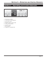
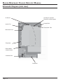
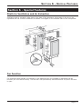
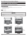
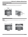
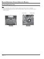
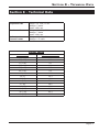
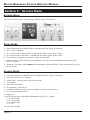
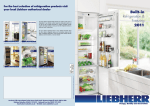
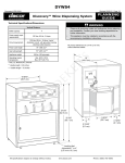
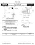
Service Manual
Beverage Cooler
Cover Model:
EF24
Please read all safety information before installing, operating, or repairing this appliance.
Service Manual
Beverage Cooler
Cover Model:
EF24
Service Information No.199/2006
TABLE
OF
CONTENTS
Section 1 - Operating and Control Elements ............. 1-1
Section 2 - Functions at a Glance ..............................2-1
Section 3 - Description of the Appliance (In Brief) ...3-1
Schematic Diagram (side view) ........................................... 3-2
Interior View of the Appliance with (e.g. WKUes 1753)........ 3-3
Section 4 - Control and Functional Components .....4-1
Section 5 - Refrigeration Circuit .................................5-1
Section 6 - Special Features .......................................6-1
Plinth for Ventilation and Air Extraction ............................... 6-1
Fan Function ........................................................................ 6-1
Section 7 - Assembly Instructions .............................7-1
Disassembling the Electronic Control System ..................... 7-1
Detaching Light Housing....................................................... 7-2
Disassembling the Sensors ................................................. 7-2
Disassembling the Fan ........................................................ 7-3
Section 8 - Technical Data .........................................8-1
Section 9 - Service Menu ...........................................9-1
Demo Mode ......................................................................... 9-1
Service Mode ....................................................................... 9-1
Sensor Test (temperature display) and Door
Contact Test ......................................................................... 9-2
Section 10 - Table of Error Codes ............................10-1
Section 11 - Customer Menu ....................................11-1
Child Proofing .................................................................... 11-1
Display Brightness ............................................................ 11-1
Changing the Unit for the Temperature Display
(°F -> °C) .......................................................................... 11-1
v
SECTION 1 - OPERATING
AND
CONTROL ELEMENTS
Section 1 - Operating and Control Elements
1. Temperature display
2. Temperature setting buttons
3. Alarm OFF button
4. ON/OFF button, interior light
5. Child proofing display
6. ON/OFF button
7. Fan operation
8. Display for ventilation ON
Page 1-1
DACOR BEVERAGE COOLER SERVICE MANUAL
Section 2 - Functions at a Glance
Control
Electronic control system
Temperature display
Digital
Temperature alarm
Visual and audible
Door alarm
Audible
Cooling
Dynamic
Defrosting
Automatic
Lighting
Fluorescent tube, permanent or when door is open
Refrigerating system
Standard compressor
Climate rating
SN – ST: +50°F to +100°F (+10°C to +38°C)
Self test
Start by button combination
Glass door
Interchangeable door hinges, k value 1.1
Activated charcoal filter
Can be changed from the inside
Suitable for installation
under worktop
Dynamic ventilation and air extraction in base
Height-adjustable
Height can be varied from 858 mm to 909 mm by adjustable feet
Page 2-1
SECTION 3 - DESCRIPTION
OF THE
APPLIANCE (IN BRIEF)
Section 3 - Description of the Appliance (In Brief)
•
The temperature can be set between +37°F and +68°F (+3 and +20°C).
•
The appliance has a compressor and a freely suspended rear wall evaporator.
•
A fan is fitted in the interior, above the evaporator. It takes in air from the front and blows it
downwards via the evaporator. Comparatively constant temperatures are attained by this means.
•
Defrosting is automatic.
•
On the ceiling is the interior light.
•
Unit ventilates and extracts air through the base. The base is closed at either side and at the rear.
Page 3-1
DACOR BEVERAGE COOLER SERVICE MANUAL
Schematic Diagram (side view)
Air Sensor
Housing for Light and
Electronic Control Wystem
Control PCB
Interior Fan
Fluorescent Tube
Back Wall Cover
Evaporator
Defrost Water
Channel Heater
Condenser Fan
Condenser
Page 3-2
SECTION 3 - DESCRIPTION
OF THE
APPLIANCE (IN BRIEF)
Interior View of the Appliance with (e.g. WKUes 1753)
Control PCB
Evaporator Cover/Air
Guide Cover
Air Sensor
Page 3-3
DACOR BEVERAGE COOLER SERVICE MANUAL
Section 4 - Control and Functional Components
Electronic control
system
6-series electronic control system – control panel PCB, power PCB
(microcontroller on power PCB)
Position: In light housing.
Setting range
+37°F to +68°F (+3°C to +20°C)
Display range
1°F to 99°F (-17°C to 38°C) - if fallen short of or exceeded, the value remains
The display is corrected with an offset value.
Temperature alarm
When:
The alarm is set off if the temperature falls short of or exceeds
the set value by 4K for longer than 20 minutes.
Audible:
4 beeps
The audible alarm can be acknowledged by means of
Alarm OFF button.
The audible alarm is suppressed during initial operation.
Visual:
Temperature display flashes.
When:
After the door has been open for 60 seconds.
Audible:
3 beeps.
The alarm can be acknowledged by means of Alarm OFF button.
Door alarm
The alarm is active again the next time the door switch is actuated.
Temperature
control
Depending on the set values and the respective sensor value, the
compressor is switched on and off.
Air sensor
Position:
On the upper side of the air guide cover.
Function:
Attends to switching the compressor on and off.
Defrosting
The evaporator defrosts during the cooling pauses
(without electric heater or similar)
Defrost water
channel heater
Position:
Adhesively affixed to the underside of the compartment liner.
Function:
• Permanently active (also when the appliance is switched off)
• Ensures that the drain does not freeze.
Interior fan
Position:
In the interior, above the evaporator.
Function:
• Attends to rapid cooling and steady temperatures
(see button combination for interior fan).
• When the compressor is at a standstill for longer than
40 minutes the fan runs permanently
(e.g. cool ambient temperature).
The fan is switched off when the door is open.
Button combination ON:
for interior fan
OFF:
The fan runs permanently.
Condenser fan
Position:
In the base, on the right.
Function:
Attends to the ventilation of the condenser and compressor
it runs in parallel with the compressor.
Page 4-1
The fan runs parallel with the compressor.
SECTION 4 - CONTROL
AND
FUNCTIONAL COMPONENTS
Control and Functional Components (continued)
Interior light
Position:
In light housing.
Function:
See Button for interior light
Button for interior
light
ON:
Interior light is permanently active.
OFF:
Interior light is active only when door is open.
Control Panel
Position:
Houses the light and electronic control system.
Function:
• switches interior fan off when door is open.
• switches interior light on when door is open.
On/Off button
Switches the entire appliance on and off.
Page 4-2
DACOR BEVERAGE COOLER SERVICE MANUAL
Section 5 - Refrigeration Circuit
Evaporator
Freely suspended rear wall evaporator
Condenser
Helical condenser (dynamically ventilated) + frame heating
Compressor
Standard compressor
Refrigerant
R134a
Page 5-1
SECTION 6 - SPECIAL FEATURES
Section 6 - Special Features
Plinth for Ventilation and Air Extraction
Ventilation and air extraction take place in the base of the appliance. A fan takes in the air on the
righthand side via a helical condenser and blows it out again on the lefthand side via the compressor.
Fan Function
For long-term wine storage, the humidity in the appliance can be increased by activating the fan
function (the LED button shines). The fan then runs permanently and switches off only when the door
is open.
Page 6-1
DACOR BEVERAGE COOLER SERVICE MANUAL
Section 7 - Assembly Instructions
Disassembling the Electronic Control System
Electronic control system:
1. Remove upper hinge pin and remove door.
2. Undo both fastening screws on the underside of the light housing, draw the housing
forwards and tip it downwards.
3. Disconnect cable.
PCBs:
1. Unclip PCB carrier.
2. Remove PCB and control PCB from PCB carrier.
To facilitate detaching the PCBs, the light housing can be pulled out in full and removed from
the appliance.
PCB Carrier
FIG. 7.1/1
Interior Light
FIG. 7.1/2
Control PCB
Power PCB
Control
Panel PCB
FIG. 7.1/3
Page 7-1
FIG. 7.1/4
SECTION 7 - ASSEMBLY INSTRUCTIONS
Detaching Light Housing
Light housing:
1. Hold light housing in a horizontal position and draw it out in a forward direction.
2. As soon as the stops strike the lugs, raise the housing a little and remove it.
Guiding Lugs
Stop
FIG. 7.2/1
FIG. 7.2/2
Disassembling the Sensors
Sensor:
1. Undo four (4) fastening screws and tip cover forwards (detach top couple of rails if necessary).
2. Remove sensor.
FIG. 7.3/1
FIG. 7.3/2
Page 7-2
DACOR BEVERAGE COOLER SERVICE MANUAL
Disassembling the Fan
Fan:
1. Place evaporator cover on rails or remove (detach top couple of rails if necessary).
2. Disconnect fan and pull from the holder. During assembly, make sure the absorber ring is
seated properly!
Plug Contact
FIG. 7.4/1
Page 7-3
Absorber Ring
FIG. 7.4/2
SECTION 8 - TECHNICAL DATA
Section 8 - Technical Data
Evaporator fan
Votage: 115 volts, 60 Hz.
Wattage: 5 watts
Speed: 1850 rpm
Condenser fan
Voltage: 115 volts, 60 Hz
Wattage: 7 watts
Speed: 1600 rpm
Defrost water
channel heater
Voltage: 115 volts, 60 Hz.
Wattage: 1.5 watts
Sensor Values
TEMPERATURE °F
(°C) RESISTANCE KOHM
95 (+35)
3.1
86 (+30)
3.8
77 (+25)
4.7
68 (+20)
5.9
59 (+15)
7.3
50 (+10)
9.3
41 (+5)
11.9
32 (0)
15.3
23 (-5)
19.8
14 (-10)
25.9
5 (-15)
34.1
-4 (-20)
45.3
-13 (-25)
60.8
-22 (-30)
82.3
-31 (-35)
112.8
Page 8-1
DACOR BEVERAGE COOLER SERVICE MANUAL
Section 9 - Service Menu
Service Menu
The service menu may be used only by customer service technicians.
Demo Mode
1. Press Light button and On/Off button simultaneously for three (3) seconds.
2. “d1” or “d0” in display.
3. d1 = demo mode is deactivated. To activate the demo mode, press “Light”.
4. d0 = demo mode is activated. To deactivate the demo mode, press “Light”.
5. If no change is wanted, do not press “Light” but “On/Off”.
6. When the demo mode is active, the compressor and fan are not activated.In the display 54°F
(12°C) is shown.
7. Attention: The demo mode cannot be deactivated by power OFF/ON. This is possible only via the
service menu.
Service Mode
1. Press Light button and On/Off button simultaneously for three (3) seconds.
2. Press “Up” once until “L” flashes.
3. Press “Light”, you are now in the service mode.
4. “rd” flashes.
5. Open and close door.
6. All segments / LEDs are lit.
7. Press all the buttons. Each press of a button is confirmed by a beep.
8. Two (2) seconds alarm tone.
9. Display L0.
10. All the loads can be individually addressed using “Up” or “Down”.
• L1: No load ON
• L2: Compressor
• L5: Interior light
• L7: Fan
11. End with “On/Off“.
Page 9-1
SECTION 9 - SERVICE MENU
Sensor Test (temperature display) and Door Contact Test
1. Press Light button and On/Off button simultaneously for three (3) seconds.
2. Press “Up” twice until “E” flashes.
3. Press “Light”.
4. The appliance is in sensor test mode and operates in the service mode.
5. All the sensor values and door contacts can be called with “Up” and “Down”.
• E1: Air sensor
• E9: Door contact (0 = door closed, 1 = door open)
6. End by pressing “On/Off” twice.
Page 9-2
DACOR BEVERAGE COOLER SERVICE MANUAL
Section 10 - Table of Error Codes
Table of Error Codes
F1
Air sensor
FE
EEPROM on the power PCB
FA, FC, FD, FE, FP
Only for factory testing. Not relevant for customer service.
F6, F7, F8, F9, SE
Only for factory testing. Not relevant for customer service.
If a sensor error is detected, the compressor is switched off.
Page 10-1
SECTION 11 - CUSTOMER MENU
Section 11 - Customer Menu
Customer Menu
In the customer menu the customer can activate the child proofing function, change the brightness of
the temperature display and alter the unit for the temperature display to °C.
Child Proofing
1. Press Light button for five (5) seconds.
2. “c” in display.
3. Press “Light”.
4. “c” in display and flashing “0” (child proofing deactivated) or “1” (child proofing activated).
5. The function wanted (c0 or c1) can be selected using “Up” and “Down”.
6. Confirm with “Light”.
7. When child proofing is active, the “Child proofing” symbol is lit in the display.
8. Change over to normal mode using “On/Off”.
Display Brightness
1. Press Light button for five (5) seconds.
2. “c” in display.
3. Press “Up” once-> “h” flashes
4. Press “Light”.
5. “h” in display and flashing “1” to “5” (5 = max. brightness).
6. Set the brightness wanted using “Up” and “Down”.
7. Confirm with “Light”.
8. Change over to normal mode using “On/Off”.
Changing the Unit for the Temperature Display (°F -> °C)
1. Press Light button for five (5) seconds.
2. “c” in display.
3. Press “Up” twice-> “°” flashes.
4. Press “Light”.
5. “°F” in display.
6. Change to “°C” using “Down”.
7. Confirm with “Light”.
8. “°” in display.
9. Change over to normal mode using “On/Off”.
Page 11-1