1
ASSEMBLY
AND
SERVICE MANUAL
FOR THE
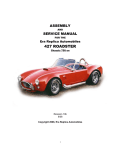
Era Replica Automobiles
427 ROADSTER
Chassis 758 on
Revision 10b
6/08
Copyright 2008, Era Replica Automobiles
1
SECTION A -PARTS NEEDED-
ENGINE
FORD FE SERIES
Remember! All piston engines have a limited torque spread.
If you decide to build a fire-breathing monster, expect to
suffer at the lower RPMs. Because the E.R.A. 427SC is light,
every hiccup is felt.
Very high octane gasoline is becoming scarce, and octane
boosters can be a pain to deal with. If you're going to do a lot
of street driving, use a conservative compression ratio: E.R.A.
turnkey cars are usually built with 9.5:1 or 10:1, maximum.
CID
Bore
Stroke
390
427
428
4.05"
4.23"
4.13"
3.78"
3.78"
3.98
BHP
net
320up
410 up
325+
Torque
net lb-ft
427
480
475
The original Cobra used the 427 CID "Side Oiler" engine in
the first cars intended for competition. The remaining cars
were equipped with a mix of 427s and 428 "Police
Interceptor" engines. Both engines are logical for use in an
"authentic" car. TheE.R.A. was designed around these
engines.
COOLING
Always use a thermostat in your system for street use. If the
engine fails to reach normal operating temperature, it may
affect driveability and lubrication. In warm climates, a
165°F to 180°F thermostat works the best. Use a restrictor
plate for racing conditions only.
The Ford FE series is not especially heavy, with the all-iron
version weighing only slightly more than 600 lbs. We have
seen complete engines with aluminum heads, intake
manifold (w/ 2 x 4bbl carbs) and water pump scale at 522
lbs. Simply adding an aluminum intake will bring the
weight on a stock 428 to 585 lbs.
The thermostat should be modified as shown on page 38.
EMISSIONS
Requirements vary from state to state. Most states require
that your car meet the specifications of the year of your
engine. Check with your local authorities. Side pipes with
catalytic converters are available but we have no experience
with them.
The best engine depends on your driving style and your
budget. If you are not experienced in the FE series engine,
be wary of building your own "exotic" engine. The FE
series is a bit quirky and you may make some very
expensive mistakes. Before you buy anything, get a good
Ford engine building book, available from Autobooks, etc.
Ford production of major 427 and 428 parts ceased in the
1980s. Fortunately, most FE engine parts are being
reproduced. You can still find original 428 cores that were
used in many full sized Fords. Using a vintage engine may
have an advantage when registering your car. When you
buy parts, keep the receipts. See Inspection, page 152.
In general, the 428 is much cheaper and easier to find than
the 427. The later vintage 428 Cobra Jet (CJ) or 428 Super
Cobra Jet (SCJ) engine is fine for all-around street use,
offering from 325HP to 425HP with very good low RPM
response and tractability. Most 428 cores can have their
performance “updated” by the addition of new heads from
Edelbrock and Shelby at reasonable cost. With an
appropriate intake manifold and carburetor, a 428 will put
out over 400 streetable bhp.
9
SECTION A -PARTS NEEDED-
REAR DRIVE/SUSPENSION ASSEMBLY
Jaguar-based Suspension
•
The E.R.A. 427SC is designed to use either the Jaguar rear
suspension (in an E.R.A. subframe) or a custom E.R.A.
suspension unit with outboard brakes. The E.R.A. unit is
available as a kit with with all our conversion parts ready for
your differential and brake parts, or as a complete assembly.
See page 43 for details.
JAG PARTS SELECTION
Custom ERA Rear Suspension
Dampers (coil-over shocks): All E.R.A. rear
suspensions require 4 dampers and coil springs (coil
over shock absorbers). Specifications are the same as
for stock Series II Jaguar XKE. XJ dampers cannot
be used. See page 23 for part numbers and page 53
for length specifications. Dampers with adjustable
spring seats and externally adjustable damping are
available from E.R.A.
USING THE E.R.A./JAG SUBFRAME:
The stock Jaguar XJ control arms and half-shafts will be
exchanged for shortened pieces when you buy the subframe
from us. Series II XKE parts will not have to be modified,
although Series III parts will.
See page 23 for application list.
The Jaguar differential is the same Salisbury unit that was
used in the original Cobra with only some casting changes. It
is adequate for 500+ BHP, and can be made even stronger by
using stub axle parts from Concours West. Gears wear is not
normally a problem even in well-used assemblies, but always
replace seals.
All XKE lower control arm mounting brackets (that bolt to
the sides of the differential) must be exchanged for XJ units.
All mounting bushings and hardware are included with the
E.R.A. subframe.
The vintage of the Jaguar differential is punched in the casting
at the lower right corner of the cover. The top number is the
year, the bottom number is a special code. (Translation: we
don't know what it's used for). A simple way to determine
whether a post-1980 unit will work is the presents of inboard
brakes. The later (inappropriate) assemblies have brakes
mounted on the hub carriers.
Do NOT replace the control arm roller and needle bearings
with aftermarket urethane bushings! The net result will be
wheel hop and generally sloppy handling.
The E.R.A. subframe requires XKE style coil-over dampers.
While not necessary, special height and damping-adjustable
units are available from E.R.A. Springs can be changed to
ones of higher rate. See page 53.
When selecting and buying a used rear end, look for:
•
Completeness - You don't need the Jag trailing arms,
but you do need everything else.
•
Limited Slip Differential - Many XJ differentials
were open. A new limited slip may be retrofitted for
about $700.
•
Brakes - Try to get serviceable hydraulic and
emergency brakes. There were no major changes in
XKE rear brake until 1968 when both the calipers
and rotors were updated. The later units are cheaper
and easier to rebuild than the early units.
•
Gear ratio - There should be a tag on one of the rear
cover bolts (for example, 43/13 on the tag = 3.31
ratio). If there is no tag, mark the input shaft flange
and the half-shaft or brake disc for reference and
rotate the axles by turning the input shaft. For every
time the axles and brake disc turns over once, the
input flange should rotate approximately 3 1/3 turns
(3.31:1 ratio) or 3 1/2 times (3.54:1 ratio). See the
chart on page 12 for the best ratio for your
engine/transmission combination.
STEERING GEAR
Starting with chassis 759, the car requires a Flaming River
gear, FR1502-3x3, with modified tie-rod adapters. This is
similar to a Mustang II unit, but shortened by 3”.
Modifications are shown on page , and complete units are
available from ERA.
FRONT ROTORS AND CALIPERS
WITH BOLT-ON WHEELS
Most mid-sized GM cars from 1970-1978 used the correct
pieces, with 2 3/8" piston calipers. Station wagons may use
different parts. Chevrolet lists the same rotor and calipers
for all sedans.
16
SECTION B -PARTS PREPARATION-
ENGINE/COMPONENTS
We cannot give complete rebuilding instructions here. What
follows are the E.R.A.-specific requirements for your
engine. General torque specifications for typical bolts are
found on page 151. Good reference books for Ford engines
are listed on page 153.
BASIC PREPARATION
Remove cooling fan from engine water pump pulley.
Install the fitting for the water temperature gage in the
intake manifold adjacent to the distributor. Note that some
manifolds must be tapped 1/2"NPT. If your manifold is
tapped 3/8" NPT, you may be able to adapt with a
Weatherhead fitting, 3200 x 8 x 6 available at your local
jobber.
Ford FE Engine
b\engmt
Note: If you have excessive engine motion or a very hightorque engine, go to
www.erareplicas.com/427man/engine/mountmod/ for mount
modification details.
Install the mounts onto the Ford small block as shown
below
Ford Small Block
b\sbengmt
The FE mounts look similar but they cannot be exchanged
from side to side. Note that the stud surface is angled
slightly from the engine side.
Install the engine mounts onto the FE block as shown
below.
32
SECTION B -PARTS PREPARATION-
CLUTCH
Install the clutch pilot bearing,, driven disk and pressure
plate.
CLUTCH THROW-OUT FORK
Forks for small and large spline transmissions are available
from E.R.A.
The standard Ford small-spline fork (see page 25 for part
number) can be left stock or bored through for easier
adjustment. Drill (remember that the part is hardened) the
indentation to 5/8” id.
TKO 500/600
Install the spacer between the mount and the mounting
boss. The offset (standard length input shaft) goes toward
the rear.
Fork installed in TKO 600
TRANSMISSION
TREMEC
The Tremec TKO series has a boss on the right side that
must be trimmed back flush in order to clear the chassis X
brace.
Note that the TKO 600 is metric-threaded (10 x .1.5) on
the inner holes, ½-13 on the outer holes.
TKO 3550, TKO II
34
SECTION B -PARTS PREPARATIONHOSE TRIMMING INSTRUCTIONS
The two lower radiator hoses must be modified to fit.
After checking fit, cut and trim the hoses as shown.
The long leg of the aluminum connecting tube goes toward
the radiator.
Lower Hose, Ford small block
Connecting hose for aluminum water pump.
This substitutes for the 21047 shown above.
SMALL BLOCK FORD
Use the center portion from the radiator to the lower
connecting tube. (You must tell us that you’re using a
small block when you order.)
429/460 FORD
Lower hoses are the same as the FE Ford.
You must use an in-line filler cap (i.e. Moroso) or an
expansion tank. If you are using an in-line filler only, you
must use an overflow system that replenishes the system
automatically.
Upper hose
Pad the "X" member if the upper hose touches it.
39
SECTION B -PARTS PREPARATIONIf you are sure that the wiper motor functions correctly and
don't want to disassemble the wiper motor itself, skip steps
4 through 8.
CONNECTING TUBES
Take out the 4 screws holding the cover to the gearbox,
and remove the cover.
Remove the circlip and washer from the connecting rod
big end, and remove the connecting rod. Note the bottom
washer.
Remove the circlip and washer from the back side of the
crankshaft, and push out the crankshaft from the housing.
Retain all the parts! Note the thrust washer on the inside
of the crankpin.
Mark the relative position of the round motor housing to
the aluminum gear reduction housing. Remove the two
long screws holding the motor housing to the frame.
Separate the two (with gentle soft hammer taps if
necessary). Do not lose the felt washer and thrust washer
in the bearing cup at the bottom of the housing.
b\wiper3
Undo the large nut and remove the cable tube/wheelbox
assembly from the motor.
Remove the wheelbox backing plates and remove the
tubes from the wheelboxes.
Inspect the brushes for wear or sticking, the commutator
for excess wear and arcing, and the lower bearing. Clean
the parts with a solvent if necessary. Work the brushes in
and out to insure free motion.
Using a tubing cutter or hacksaw, cut off approximately 2
3
/4" from one end of the original tube between the right
wheelbox and the motor. Save the nut and the piece of
tubing. Use the short tube for the guide at the end of the
second wheelbox.
Install the armature carefully into the gear housing until it
contacts the sides of the brushes. Using a hook shaped
wire or other appropriate tool, retract each brush in turn so
that the commutator can slide past the edges of both
brushes and continue into the gear case
Slide the nut onto tube shorter tube supplied (the one with
just one end flared).
Flare the end of the tube with the nut. Slide the drive
cable through the tube. If the cable is tight at the new
flare, use a 1/4" drill bit to "clean" the inside of the tube.
Put 1 or 2 drops of oil in the lower bearing of the armature
housing. Excess oil will contaminate the brushes later on.
Install the armature housing, aligning the marks on the
housing and the frame. Reinstall the long retaining
screws.
MOTOR PREPARATION
STROKE CHANGES
Remove the plastic gear from the crankshaft by supporting
the edge of the gear and tapping the shaft with a soft
hammer. Be careful not to damage the circlip groove.
The position of the crankpin must be changed in order to
increase the stroke of the cable: Punch the underside of
the crank plate exactly opposite the center of the crankpin.
Use a 3/8" Blair spotweld cutter to cut the pin from the
plate, drilling from the back side at the punch mark. The
pin will be removed, together with a small piece of the
plate.
51
SECTION C
-CHASSIS PREPARATION-
Body pre-mounted on chassis option
Most of the time-consuming items listed in this section are
already done, although it couldn’t hurt to check critical
fasteners. You can skip all the Section C items except
removing the windshield, bumpers, lights and fuel filler
cap in preparation for paint.
BODY REMOVAL
The body must be removed to paint the chassis, but is not
necessary to remove the body from the chassis to paint the
body. All E.R.A. turn-key cars are painted with the body
already bonded to the chassis, but without mechanicals
installed. This requires careful masking to minimize
overspray, but guarantees good body panel fit. Installation
of all the mechanical components is easy with the body
on the chassis. It is, in fact, much harder to install the
body over the mechanical components.
When doing any disassembly, note any adjusting shims
and their location. Mark each for reassembly.
DOORS, HOOD AND TRUNK LID
Note the location of the hinges and the number of shims for
all pieces.
Remove the door hinge covers.
ROLL BAR:
Remove the doors, hood, and trunk lid from their hinges.
Note that the basice kit is shipped with short pieces of
half-round rubber taped to the door openings. This is put
there to prevent rattles and wear when the car is shipped.
You may discard the rubber, etc. Lengths of new gasket
are included in the parts boxes shipped with the kit.
Remove the center access panel from the rear bulkhead.
See page 83.
Remove the bolts from roll bar brace, one at each leg, and
at the top and bottom end of the rear brace.
Remove the shim washers from the lower end of the brace
and slide the brace down to disengage the upper slip joint.
Remove the door hinges and metal closing panels behind
door hinges.
Pull the roll bar hoop up and out from the chassis.
Remove the hood and trunk hinges, noting their location.
“L” and “R” are stamped into the hood hinges. The trunk
hinges are the same from left to right and are stamped with
“T”.
Remove the rubber grommets from the body.Doors, etc:
Remove the filler panel below the door opening.
Remove latching hardware from the main body, including
the hood firewall latches..
BUMPERS, BUMPER BRACKETS:
Remove the aluminum interior panels that are below the
door openings and the aluminum firewall.
Front: If you have the optional nudge bar(s), detach them
from the overriders.
RADIATOR AND SHROUDING:
Remove both fresh air inlet ducts and screen from the front
body.
Remove the (optional) oil cooler and shrouding. See page
90.
Remove each bumper/tube assembly from its mounting
point. The upper nut is accessible from inside the nose.
The lower nut is accessed through a hole in the inner
splash panel.
Remove the (optional front fan assembly. See page 89.
Remove the rear fan on its bracket. See page 88.
Remove the side and lower shrouding (3 pcs.) from inside
the grill opening.
Rear: Unbolt the bumpers from their mounting brackets
(upper bolt) and chassis (lower bolt). The nuts on lower
bolt are reached through the access holes on the bottom of
the rear chassis cross member. If nudge bar is fitted,
remove as a unit.
Remove the upper radiator mounting tab and gently lay the
radiator back against the chassis. Soft paddling will help
insure that nothing is damaged.
Remove the top radiator shroud. See page 88.
56
SECTION D - BODY/CHASSIS ASSEMBLY
VOLTAGE REGULATOR
More chassis and body ID numbers
The regulator (part number on page 26) installs with #10
sheet metal screws bolts on top of the left foot box into
captive speed-nuts.
The chassis is stamped with the ID number in three places:
•
The left front X member, inside the top shock mount.
•
On the transverse tube behind the engine(usually
covered by the aluminum firewall panel. On the
outside of the frame just inside the right rear tire.
The body is marked inside the hood opening, on the left
return lip about a foot from the front of the opening.
BATTERY TRAY
(Pre-installed) The standard front-mounted battery is
bolted in place onto the front of the right foot box and to
the top of the front outrigger. It’s pre-installed on every
chassis, so the holes are already in place.
d\voltreg
d\battery_mount
BATTERY REMOVE AND REPLACE
The engine-compartment-mounted battery is accessed by
removing an access panel at the rear of the right front
wheel.
•
Remove the hose from the fresh-air valve.
•
Note that the top panel screw and the three lower
screws are removed from the engine-compartment
side and the lower screws from inside the wheel
well. The bottom edge is secured to the chassis
outrigger with sheet metal screws.
64
SECTION D - BODY/CHASSIS ASSEMBLY
From inside the grille opening or engine compartment, lift
the hinges assemblies into place. Align and bolt to the
body and hood with the shims used earlier. Tighten all
bolts.
Carefully lift the hood, checking the front edge clearance.
Adjust and/or change shims if needed.
Adjust the hood strikers on the firewall so that the hood is
flush with the body. The hood seal will be compressed
slightly, eliminating rattles.
HOOD PROP
(Pre-installed)
The upper and lower stay brackets are (factory) attached as
shown.
ebod\trnkstay
HOODPROP
Note the orientation of the keyhole slot and the bend in the
rod.
TRUNK LID
Tape the gasket to the main body as shown on page 78 for
bodywork alignment prior to painting.
Bolt the trunk hinges (they are marked with a T on the lid
side) loosely onto the body with any shims found earlier.
Loosely bolt the trunk lid (with factory shims) onto the
hinges. Carefully close the lid, not letting the front edge
contact the body. Center the lid in the opening. Slowly
lift the lid just enough to get your arm (and a wrench)
inside and snug the bolts on the lid part of the hinges.
Remember to check the front edge while lifting lid.
The lid can be adjusted further by moving the lid and
hinges in unit at the connection on the inner panel.
Tighten bolts and recheck fit.
TRUNK STAY
(Pre-installed) Attach the trunk stay to the trunk lid as
shown, using the sheet metal screws at the bottom,
stainless steel dome head screws at the top.
68
SECTION E -BODY PREPARATION-
Stretch the door pocket into place with its forward edge
even or slightly past the front edge of the door frame and
2
/3 of the way up from the hinge bottom mounting holes.
Hold the top of the pocket in place with masking tape.
Carefully stretch the material over and partially around the
attachment plate.
Attach the hinge loosely with the two upper bolts. Mark
and punch holes for the two lower bolts through the door
pocket. Attach the bottom of the hinge and snug the bolts.
Before attaching the pocket to the door, glue the rug (items
7 and 15 in the rug installation diagram on page Error!
Bookmark not defined.) to the inside of the door with
contact cement. Install the door pocket and the latch onto
each door.
Remove the attaching plate from the door. Tape or clamp
the upper edge to a flat surface and finish gluing the edge.
Gently and evenly pull the bottom edge of the door pocket
down over the bottom edge of the door. Stretch only
enough to eliminate any wrinkles. Hold in place with
several pieces of tape. With a temporary marker, trace the
profile of the lower edge of the attaching plate onto the
pocket. Also, mark where both ends of the plate fall.
DOOR WEATHERSEALS
Lay the doors, outer surfaces down, on a soft surface.
Clean the door edge and rubber with a mild solvent. Glue
the door weatherseal (start with about 60" - trim the ends
later) provided onto door lip about 1/8" from the door edge
using contact cement or weather-strip adhesive. Don't
stretch the weather-stripping: It will eventually shrink to
its original shape, pulling away from the corners. Trim the
ends of the weather-stripping as shown.
eint\doorpnl3
Remove the door pocket from the door and trim the edge
of the door pocket approximately 1" outside the marked
line. Cut wedges out of the edge of the material almost up
to the marked line.
E\DOORGASK
SIDE CURTAIN FERRULES
eint\DOORPANL1
FERRULE
Re-install the pocket onto the door. Apply contact cement
to the edge and backside only of the attachment plate and
the back side of the pocket material. Let dry to a tack-free
condition.
Slip the ferrules into the holes on the top of the doors and
note the length that each extends past the inner panel.
85
SECTION E -BODY PREPARATION-
Mark each ferrule so there are no more than 2 or 3 threads
showing between the mark and the door surface on its
shortest side,
All components are pre-installed on every kit.
Cut off the excess at the mark, and slightly round off the
edges with a file or sander.
Hold the ferrules in place with the retaining rings
provided. Seat the retaining rings against the door surface
tightly.
DOOR PULL STRAP (OPTIONAL)
Drill a hole (#30 bit) just to the rear of the side curtain
ferrule. Loop the strap over the latch ball and use the
screw and countersunk washer at the front.
DOOR INSTALLATION
The doors can be installed now, but to make other
operations easier, it’s best to wait until near the end. See
page 123 for installation details.
e\throtlnk
Fit the rod end (C) through the footbox using a large
washer on either side of the hole.
Install the pedal assembly (A) with the linkage bracket (B)
onto the foot box. At the back, secure to the fiberglass
with bolts through the brace bracket and spacers. At the
front, secure with the front steering flange bearing bolts.
ACCELERATOR PEDAL AND LINKAGE
Loosely bolt the bracket (D) onto the engine using the
rear-most intake manifold bolt. The final object is to have
the cross-shaft as parallel to the firewall as possible, so the
orientation of the bracket may be changed so that the
vertical and rod-end support are toward the firewall.
Adjust the placement of the rod end in the bracket so that
the cross-shaft is roughly horizontal.
Fit the left end of the transverse link (F) to the rod end on
bracket (B). Secure with a cotter pin. Slide a rod end (E)
onto the transverse link and bolt to the bracket (D).
Note: This linkage can be adapted to most engines. If
yours requires something different, please call us. The FE
dual-quad setup requires an additional linkage assembly.
86
SECTION E -BODY PREPARATION-
COOLER WITH REMOTE FILTER
FUEL TANK
Mount the remote filter on the water pump with the E.R.A.
adapter bracket. Some modifications to the pump might be
necessary.
The 19-gallon aluminum fuel tank is baffled, with one-way
doors separating the volume into four sections, capturing
the fuel toward the front/center of the tank during
cornering and acceleration.
A drain plug is at the right front of the tank bottom.
The fuel sender is in the center-front section of the tank,
and installed at E.R.A. If you find it necessary to remove
the sender, use a fuel-resistant sealant like Versachem
Gasket Sealant #3 Aviation. A jumper wire is taped to the
top of the tank that mates with the connection to the rear
harness.
INSTALLATION
Use a grinder to remove 3/8” from the boss.
Place the tank under the car and connect the sending unit
wire(s).
Assemble the other components as shown. The water
pump may require modifications to the bottom mounting
boss (instructions included with cooler kit).
Raise the tank between the frame rails, guiding the filler
5
neck through the body hole. Hold in place with one ( /16"
USS) bolt per side. Install the rest of the bolts and
washers.
ebod\oilclr5
WITH IN-LINE THERMOSTAT
Ebod\Fueltank
Connect the fuel outlet on the center rear of the tank to the
steel line on the chassis (both 3/8" OD) with a length of
rubber fuel line. An in-line fuel filter can be conveniently
installed within this section of line. Use clamps on all
connections.
Slide the seal plate over the fuel tank neck and secure with
the screws. See the filler cap illustration.
oilclr7
92
SECTION E -BODY PREPARATION-
Remove excess RTV and clear the drain hole with a wire,
etc. Install the vent and drain hoses to the lower flange as
shown. Run the drain hose through the hole in the bottom
corner of the well at the side of the trunk.
FUEL FILLER CAP
The cap and outside flange are indexed with punch marks
(or a common number} on the outside edge of the upper
mounting flange. This corresponds to where the latch of
the filler cap falls when the cap is fully screwed onto the
flange.
Pass the vent hose through the seal plate and connect to
the aluminum tube that comes through the hole in the
tank’s mounting flange.
Note the odd hole falling just outside the upper flange on the
body and lower flange. A water drain for the filler well is
integrated into the bottom flange of the filler cap. The tube
in the lower mounting flange channels water out of the well ,
through a hole in the trunk.
FLANGE
Put a generous amount of RTV silicone gasket sealer on
the top surface of the flange.
Line up the drain hole on the flange and the body. Hold
the lower mounting flange in place on the underside of the
fender.
INSTALLATION
ebod\fuelfill
Place the gasket and upper flange on top of the fender,
with the flange markings toward the right side (at 3
O'clock as viewed from above). Hold everything together
with the stainless steel screws provided.
93
SECTION F -SUSPENSION ASSEMBLYLubricate the insides of the upper chassis brackets with
lithium grease so that the sides of the rubber bushing will
slide into them. Guide the suspension assembly into the
chassis brackets. Using a little light oil on the threads,
install the 5/8" bolts with flat washers, but don't tighten yet.
REAR SUSPENSION, JAGUAR-BASED
XJ COMPONENTS IN E.R.A. SUBFRAME
Thread the trailing arms onto the rod ends (with jam nuts)
already installed on the lower control arms. Thread on
until one or two threads show. Leave the jam nuts loose.
d\eracage
Note that the trailing arm bushing is angled slightly
relative to the trailing arm tube. See the bottom of the
illustration on page 99.
On one side of the car: Rotate the trailing arm so that the
bushing angle matches the chassis bracket. Hold the
bushing against the inside of the chassis bracket and sight
through from the outside hole. Use a large screwdriver to
move the assembly so that the sight is straight into the
threaded portion of the chassis bracket.
Slip the aluminum spacer between the outside of the
trailing arm bushing and the chassis bracket. See the
illustration above. Slide the 1/2" x 3" bolt through the flat
washer, upper hole in the bracket, spacer and trailing arm
bush, engaging the (locking) threads in the chassis. No
lock-washer is necessary.
f\rearsusp
Raise the rear suspension assembly into position with a
floor jack, guiding the forward ends of both trailing arms
into the brackets on the sides of the frame. Don’t install
the bolts yet.
Move to the trailing arm on the other side of the car. Sight
through the hole in the chassis and determine whether the
length of the trailing arm will have to be adjusted. Screw
the trailing arm in or out on the rod-end as necessary.
If the assembly does not line up perfectly, pry or pull on
the hub carrier to shift things around while installing the
spacer and bolt. If the holes do not exactly line up,
grinding a taper on the bolt may make it easier to get the
threads to start. Torque the bolts on both sides to 45 lb-ft.
Tighten the upper pivot bolts to 90 lb-ft.
Connect the brake flex-line to the bracket on the chassis.
XKE HANDBRAKE LEVER AND CABLE
You can use then entire XKE handbrake cable linkage as
shown below.
f\tralarm
99
SECTION F -SUSPENSION ASSEMBLYIf even more adjustment is required, a 7/8" bore Tilton
cylinder can be substituted for the BMW clutch master
cylinder. A new clutch hose is also required. Special
Order Only.
BRAKE AND CLUTCH PEDAL
ADJUSTMENT
d\braklink
Because the front brake wheel cylinders require more fluid
than the rears, the balance bar is always set up with the
outside push-rod 1/4" longer than the inside one. There are
flats machined on the one side of each connecting rod end.
Install the rod ends on the balance bar with the flats
toward the balance bar housing. See above and page 143.
d\brpedal
INSTALLATION
NOTE ON THE BRAKE BALANCE ADJUSTMENT
If necessary, clean and grease the needle bearings in the
chassis and in the brake pedal.
The rod length has no effect on the front/rear brake bias
(which brakes lock first). If necessary, the bias can be
adjusted as described on page 142.
Slide the pivot shaft through the chassis bearings with the
splined end toward the inside. If the engine is installed,
the shaft must be installed from the outside of the chassis.
For a preliminary setting, adjust the outer rod so that there
are 3/4" of threads showing on the outer master cylinder
rod, 1/2" on the inner rod (with the jam nuts against the rod
end.)
Install the thrust washer(s), brake pedal, and clutch pedal
onto the shaft. Secure the clutch pedal with the shoulder
screw.
Install the clutch throw-out arm onto the splined end of the
shaft. Orient the throw-out arm approximately opposite
the pedal. See the illustration on page 137.
To adjust the orientation of the clutch arm, change the
length of the connecting rod between the clutch pedal
throw-out arm and the clutch master cylinder:
Remove the retaining clip and the clevis pin.
Loosen the jam nut at the clevis. Turn the threaded rod to
change the length as necessary.. When finished, tighten the
arm set screw.
For balance bar parts installation, see page 142.
Clutch height adjustment is covered on page 104.
BRAKE PEDAL HEIGHT
Master cylinder installation is described on page 61.
For people of average height, set the distance from the rear
of the pedal face to the forward part of the foot-box to
about 7". If you are much taller or shorter, you may move
the pedal up to 3/4" forward or backward as needed.
To change the brake pedal height, turn both threaded
rods equally in or out.
Check the tightness of the brake lines and switch fittings.
103
SECTION G - BODY/INTERIOR
CARPETS
INTERIOR
REAR PANEL
After masking the body, spray or brush contact cement
on the panel areas and the back sides of the vinyl and
carpet.
Install the side carpets, starting by lining up the
corner(s) as shown.
Install the vinyl on the central aluminum side panels.
Trim even with the vertical edges and leave a short
amount at along the floor.
Carefully form the carpet over the wheelhouse bulge and
push into the side and top areas. Trim off the excess
material.
115
SECTION G - BODY/INTERIOR
Attach the tunnel carpet (#17) with about 1" extending
past the front edge, allowing the carpet to be folded over to
the backside and glued. Cut out for the shifter, ashtray and
hand brake lever. Screw the tunnel into place.
To make cleaning easier, the two-piece floor carpets are
held in place with snaps and Velcro. Fit the carpets in
place and mark the floor where the snaps are to go. Drill
1
/8" holes and screw the snap bases into place. Remove
carpets to fit seats.
FRESH AIR CABLES
Lubricate the rubber grommet located midway up the front
of the driver’s footbox on the left hand side, with silicone
spray or petroleum jelly.
Push the cable through the grommet and install the cable
loop on the fresh air control valve as shown on page 63.
eint\doorrug1
Attach the cable to the side of the footbox with a cable
clamp.
Replace the door strikers as described on page 123. The
added thickness of the carpet should make the rear edge of
the door flush with the body. If not, add or subtract shims.
Also see the illustration on page Error! Bookmark not
defined..
HAND BRAKE LEVER COVER
Using the figure below as a guide, open up the hand brake
lever cover and align the cut-out section on the inside flap
around the hole in the transmission tunnel behind the
lever, bunching it up as necessary in the center. Attach the
front edge of the boot by drilling holes through the fabric
into the tunnel.
Hold the attaching plate against the cover and tunnel.
Drill four 1/8" holes into the tunnel. Attach the plate and
cover to the tunnel.
The door should latch on the second catch without being
slammed. If it doesn't shut all the way with a solid
"chunk", check for latch/striker misalignment or an
interference fit between the two parts
To check for misalignment, hold the latch lever in the open
position and shut the door without putting any pressure on
it up or down. The door latch should seat into the striker
without resistance or sharp contact sounds. Re-align
vertically if necessary.
Open and shut the door several times, then check the
striker receptacle of the latch for shiny spots. File these
spots, being careful to hold the file flat. Recheck fit, and
repeat the process if necessary.
eint\ebtrim1
Install the dead pedal over the carpet.
Re-bolt the hand brake lever in place.
Fold the outer flap of the cover over the lever and attach to
the inner flap with the Velcro and snap.
121
SECTION H
-FINAL OPERATIONS Attach a small hose to the slave cylinder bleeder nipple,
emersing the other end of the hose in a small cup of fluid.
9
Loosen the nipple about 2/3 turn with a /32" or 7 mm wrench.
CLUTCH HYDRAULICS
PRESSURE HOSE INSTALLATION
Work the arm on the clutch pedal shaft (instead of pushing
on the clutch pedal itself) until only clear fluid comes out of
the hose.
See page 35 for an illustration of the slave cylinder.
Close the bleeder nipple and pump the clutch pedal several
times. If there is more than 1" travel at the pedal before
resistance is felt, repeat the bleeding procedure.
ADJUSTMENT
The slave cylinder has an internal spring that keeps a small
amount of pressure to extend the piston at all times. Most
throw-out bearings will operate with the small constant
pressure involved. Those that cannotmust use a return
spring and be adjusted periodically.
If you wish, you can use this preload to automatically keep
the clutch adjustment at “zero” clearance. This will,
however reduce the life of the throwout bearing. Since clutch
wear will be most seen when the driven disc is being broken
in, you may want to keep the “automatic mode” during the
first couple hundred miles and then install a return spring.
See page 104 for clutch pedal height adjustment.
WITHOUT RETURN SPRING
With BMW Master Cylinder
Increase the length of the throw rod by unscrewing the ball
end, forcing the piston in the cylinder to just bottom out.
Note that the cylinder is spring loaded to the fully extended
position.
Decrease the length of the adusting rod so that there is
about 1/4" movement when you push the transmission arm
toward the front of the car.
With Tilton Master Cylinder
Check the tightness of all fittings before bleeding.
BLEEDING
The car must be level or with the front end slightly higher for
this operation
f\cltchadj
Fill the brake/clutch reservoir with DOT 3 or DOT 4 fluid.
Silicone fluid is not recommended.
137
SECTION H
-FINAL OPERATIONS -
SETUP
COOLING SYSTEM
The optimal operating temperature for most FE engines is
about 185F (85C). This will keep water condensation in
the oil to a minimum and allow adequate oil flow. We do
not recommend using a restrictor plate in place of a
thermostat unless the car is used exclusively for track use.
WATER HOSE LAYOUT (FE)
Install the radiator hoses (and optional top tube connector)
and lower hose connector. The hose part numbers and
instructions for modifying the front lower hose are covered
on page 39.
See page 150 for your best mix of water and anti-freeze.
With a 15psi pressure cap, the boiling point will be raised
to about 240°F.
The radiator cooling fan thermostatic switch is in the lower
hose connector. Connect the harness wires as shown on
page 81 and detailed in the wiring instructions. (There is
also an over-ride switch on the dashboard).
Fill the system through the expansion tank, leaving about
1½” of expansion space above the coolant level.
See the diagrams below for the cooling system circuits.
With some engines (especially the FE Ford), air tends to be
trapped in the intake manifold and cylinder heads. To
remove the trapped air:
Do NOT remove the spring from inside the long lower
hose. It prevents the hose from collapsing at speed.
Standard one-piece upper hose
•
Drill the thermostat as shown on page 38.
•
Open the bleeder at the upper right of the radiator.
Fill the system with the cooling mixture. Once water
flows bubble free from the radiator bleeder, shut the
valve. Actually, we usually fill the system with
water first and pressure test for leaks, then drain half
the water out. We can also tell the condition of the
cleanliness of the cooling system by the drain water.
•
With the expansion tank full, loosen the water
temperature fitting on the intake manifold. Air will
be expelled. When nothing comes out but fluid,
tighten the fitting. If you have a heater, it may be
necessary to bleed air from the system by
disconnecting a hose at the heater nipple.
•
Repeat the bleeding process after the car is run.
More air will usually come out.
•
Check the hoses and retighten all the hose clamps.
OVERHEATING:
Use a 165°F -180°F thermostat for street use. Leaving the
thermostat out will cause overheating. The boiling point of
a water/anti-freeze mixture with a 15 psi cap is over 230°F.
It is not harmful (and normal) for the water temperature to
rise to 210°F - 220°F with the car not moving.
We do NOT recommend using an underdrive
waterpump pulley on the street..
AT SPEED
The E.R.A. 427SC uses an oversized radiator made by
Griffin, rated for 600 bhp. Overheating at speed is almost
always the result of incorrect engine settings, usually
retarded ignition timing. Check your dynamic timing at
idle and 3000-3500rpm, or as recommended by your engine
builder. Sometimes an extremely tight (new) engine can
cause overheating.
With upper connecting tube
144