1
USER MANUAL FOR THE ELECTRONIC
SYSTEM
SST 2015
USER MANUAL FOR THE
ELECTRONIC SYSTEM
SST 2015
NOTE Provides key information to make the procedure easier to understand and carry out.
CAUTION Refers to specific procedures to carry out for preventing damages to the vehicle.
WARNING Refers to specific procedures to carry out to prevent injuries to the repairer.
Personal safety Failure to completely observe these instructions will result in serious risk of personal
injury.
Safeguarding the environment Sections marked with this symbol indicate the correct use of the vehicle
to prevent damaging the environment.
Vehicle intactness The incomplete or non-observance of these regulations leads to the risk of serious
damage to the vehicle and sometimes even the invalidity of the guarantee
INDEX OF TOPICS
KIT PRESENTATION
PRE
MOTORCYCLE ASSEMBLY
MON
PDA
PAL
PRELIMINARY PROCEDURES
AND CALIBRATIONS
PRO
INDEX OF TOPICS
KIT PRESENTATION
PRE
Kit Presentation
SST 2015
Index:
KIT DESCRIPTION
1. ELECTRONIC CONTROL UNIT
2. INSTRUMENT PANEL
3. PDA
4. OPTIONAL
5. STRATEGIES
6. SOFTWARE PRESENTATION
Based on the experience of racer motorcycles during the last 20 years, Aprilia Racing has developed
an electronic racing kit dedicated for the track use for the vehicle "RSV4SST". Purpose of this document
is to describe the electronic kit, its potentiality and the installation on the motorcycle.
Kit Description
The electronic kit consists of:
Control unit
It is the electronic control unit developed and made by Aprilia Racing The electronic control unit APX2
is the electronic control unit for the management of the engine and the acquisition of the data.
For the management of the motorcycle parameters and the data analysis the ARES and ABM BASE
software are supplied
Instrument panel
It is the Matrix\RSS instrument panel developed by Aprilia Racing. With this it is possible to display a
lot of information among which rpm (analogue or digital display), important engine parameters and
parameters for the driver.
PDA
The PDA is the interface between the user and the electronic system of the motorcycle. This interface
is included in the motorcycle options, but it is necessary to perform several engine parameter adjustments (necessary for the correct operation of the engine) and to display the acquisition base parameters.
The PDA is supplied together with a connection cable to the motorcycle.
Optional
This is a list of the possible options of the electronic kit:
PRE - 6
SST 2015
•
Kit Presentation
RACING PUSH-BUTTON PANEL Used in replacement of the standard push-button panel
of the left semi-handlebar.
•
GPS Used for the beacon and for the visualisation of the track path.
•
LOAD CELL Used for the activation of the Kicker\Blipper strategy.
•
SUSPENSION POTENTIOMETER Used for the acquisition of the fork and shock absorber
extension.
•
FRONT BRAKE PRESSURE SENSOR Used for the acquisition of the front brake system
pressure
•
LAMBDA KIT Used for the acquisition of the stoichiometric ratio of each cylinder. It is further
possible to activate the automatic correction of injection times (automatic lambda strategy).
•
REAR LIGHT Used to increase the visibility of the vehicle in situations of limited visibility
(WET). The device is mandatory for the participation to some races and/or championships.
Strategies
This is the list of the strategies and parameters integrated in the system:
•
RPM LIMITER MAX rpm limiter can be configured for each gear.
•
PIT-LANE SPEED LIMITER Pit-lane speed limiter, programmable.
•
ETC Electronic throttle grip control.
•
VTP Variable intake duct position.
•
TCS Traction control system.
•
ADAPTIVE TCS Adaptive traction control.
•
DISTANCE BASED Strategies and/or parameters configuration system based on the distance.
•
ENGINE BRAKING Programmable engine braking for each gear.
•
POWER REDUCTION Power reduction system for each gear.
•
WHEELIE CTRL Anti wheeling system, can be configured.
•
LAUNCH CTRL Assisted launch control.
•
BACKLASH CTRL Anti-jerk clearance recovery system.
•
QUICK GEARSHIFT Power-assisted gear shifting system.
•
KICKER STRATEGY (BLIPPER STRATEGY)-(OPTIONAL) Assisted downshift system.
•
LAP TIME-(OPTIONAL) Lap time detection system.
Software presentation
This is the list of the software offered and usable by our system:
•
ADVIEWER Is the software developed by Aprilia Racing used to download, display and
analyse the acquired data. This software allows downloading the data and then analyse the
same with additional tools such as complex mathematical functions, different types of graph,
PRE - 7
Kit Presentation
SST 2015
distance-time, XY, XYZ, histograms, histogram maps, simple graphs with circuit or parametric, static, alarm management , conditions management, exporting to other formats, and
much more ....
•
WIN CHANNEL EDITOR Is the software developed by Aprilia Racing used for the management of the acquisition table of APX2. This software allows to modify the Alias of the control
unit, cancel all acquisition data, connect in real time to the acquisition system, receive,
transmit, modify the acquisition table of the motorcycle.
•
ARES Is the software developed by Aprilia Racing used for the complete management of
the parameters and strategies of the motorcycle. It is possible to apply the modifications to
the injection maps (interfacing with Mapcorrector),add\remove curves (Dry\Wet) and modify
all parameters, perform all preliminary settings of the motorcycle (possible also with the
PDA) and much more…
•
MAPCORRECTOR Is the software developed by Aprilia Racing used for the correction of
the fuel injection of the motorcycle. The software receives the data of the lambda probe
reading from the data acquisition file, the injection times used and though a calculation algorithm, which takes account of a preselected target, creates a fuel injection map.
•
ANALYSIS Is the software developed by Aprilia Racing used for the implementation of the
motorcycle. This software allows to have a general view of the implementation of the motorcycle both numeric and graphic. It is possible to export all data in a file excel to have a
detailed report of the performed modifications, of each test of one day or an entire event.
Calculate and simulate future configurations (after a front and rear modification, refill the
calculated parameters). It is therefore possible to analyse the calculated configuration before
applying the modifications to the motorcycle.
PRE - 8
INDEX OF TOPICS
MOTORCYCLE ASSEMBLY
MON
Motorcycle assembly
SST 2015
Index:
PRELIMINARY OPERATIONS
1. THINGS TO REMOVE FROM THE MOTORCYCLE
2. THINGS TO REPLACE ON THE MOTORCYCLE
3. INSTRUMENT PANEL SUPPORT MODIFICATION
4. CONTROL UNIT SUPPORT ASSEMBLY
5. INSTRUMENT PANEL ASSEMBLY ON CONTROL UNIT SUPPORT
6. VEHICLE WIRING HARNESS ASSEMBLY - RSV4 FACTORY A-PRC 2015
7. ENGINE WIRING HARNESS ASSEMBLY - RSV4 FACTORY A-PRC 2015
WIRING HARNESSES
8. VEHICLE MULTI-WIRE CABLE HARNESS
9. VEHICLE SINGLE WIRE CABLE HARNESS
10. ENGINE MULTI-WIRE CABLE HARNESS
11. ENGINE SINGLE WIRE CABLE HARNESS
12. MATRIX/RSS DASHBOARD (E09042) INSTRUMENT PANEL DEMAND WIRING HARNESS
13. DISPLAY
14. PUSH-BUTTON PANEL LED SIGNALLING
15. STANDARD PUSH-BUTTON PANEL MODIFICATION
16. LEFT PUSH-BUTTON PANEL DESCRIPTION
17. RIGHT PUSH-BUTTON PANEL DESCRIPTION
Preliminary operations
Things to take off the motorcycle
The first operation to be made is to remove from the standard motorcycle the unused parts:
•
Vehicle cable harness
•
Engine cable harness
•
Front light
•
Rear light
•
Front turn indicators
•
Rear turn indicators
•
Ignition switch assembly
•
Left push-button panel (requests a modification)
•
TCS push-button panel
•
Instrument panel
•
Engine control unit
•
Stand
MON - 10
SST 2015
•
Motorcycle assembly
MAP sensors (pressure under throttle valve)
Things to be replaced on the motorcycle
•
Gear potentiometer from linear selector
•
The connection pipes of the MAP sensors with the holes closure caps of the pipes under
throttle valve
Change instrument panel support
The instrument panel support to be able to house the inertial platform and to mount the engine control
unit holder support must be modified.
•
The marked hole must be widened up to 5mm in diameter.
•
Remove the part marked in red.
MON - 11
Motorcycle assembly
•
SST 2015
The modified support will be the one in the image
Control unit support assembly
Mount the accessories on the bar as shown, paying attention that all elastic plates (1) are M6 except
the two indicated (2) that have the hole M5.
MON - 12
SST 2015
Motorcycle assembly
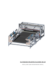
Instrument panel assembly on control panel support
In the figures shown below, the completely mounted instrument panel control unit is visible
MON - 13
Motorcycle assembly
SST 2015
VEHICLE CABLE HARNESS MOUNTING - RSV4 FACTORY APRC 2015
The following photos are used to give indications on how to mount the vehicle wiring harness correctly
on the motorcycle following the specifications for which it was designed.
Below a list of information to keep in mind:
NOTE
BEFORE MOUNTING THE WIRING HARNESS, FIT THE COMPLETE INSTRUMENT PANEL SUPPORT TO THE MOTORCYCLE ENGINE.
PAY ATTENTION THAT ALL BRANCHES OF THE WIRING HARNESS, ONCE POSITIONED, ARE
NEVER TOO TIGHTENED.
THE WIRING HARNESS SHALL NOT PASS NEAR MATERIAL OR EDGES, WHICH THROUGH THE
VIBRATIONS OF THE VEHICLE, COULD COMPROMISE THE INTEGRITY. IN CASE THIS IS NOT
POSSIBLE, PROTECT THE ZONE OR THE WIRING HARNESS IN ORDER TO AVOID BREAKAGE.
THE GROUND EYELETS MUST BE CONNECTED TO METAL PARTS, ELIMINATE ANY PAINTING
OR ANODIZING THAT COULD COMPROMISE THE CONDUCTIVITY
MON - 14
SST 2015
Motorcycle assembly
MON - 15
Motorcycle assembly
MON - 16
SST 2015
SST 2015
Motorcycle assembly
MON - 17
Motorcycle assembly
MON - 18
SST 2015
SST 2015
Motorcycle assembly
MON - 19
Motorcycle assembly
SST 2015
VEHICLE CABLE HARNESS MOUNTING - RSV4 FACTORY APRC 2015
The following photos are used to give indications of what may be an optimal mounting of the engine
wiring harness on the motorcycle RF 2015.
The indications for the mounting are the same as listed for the mounting of the vehicle wiring harness.
As you can see in the photo, it is recommended to mount the wiring harness on the engine before
installing it on the motorcycle.
MON - 20
SST 2015
Motorcycle assembly
MON - 21
Motorcycle assembly
MON - 22
SST 2015
SST 2015
Motorcycle assembly
MON - 23
Motorcycle assembly
MON - 24
SST 2015
SST 2015
Motorcycle assembly
MON - 25
Motorcycle assembly
MON - 26
SST 2015
SST 2015
Motorcycle assembly
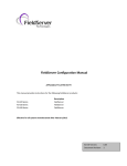
CABLE HARNESSES
VEHICLE MULTIFILAMENT CABLE HARNESS
ENGINE
CONN. MIL
ref. C
FRONTSUSP
ref. AI
PURCHASE
ref. AC
FRONTBRAKE
ref. AI
CHASSIS GROUND 2
ref. M
REARSUSP
ref. AF
"APX 1"
CONN. MIL.
55 poles F
ref. A
ETHTXP
TCK2P
TCK4P
USB2N
ETHTXN
TCK2N
TCK4N
TCK3P
TCK1P
USBN
USB2P
TPSRED2
P. GEAR LIN
TCK3N
TCK1N
ETHRXP
GND
USBP
TC+
REARBRAKE
REARSUS
TPS2
ETHRXN
VBAT
ACANL
GND ANA2
GND ANA1
ANALOG 4
PITLANE SWITCH
P_OIL_MIN
NTC3
ACANH
IC3
AIR_TEMP
TV_FEEDBACK
POIL
ANALOG 1
ENG_TEMP
V10B
IC1_FRONTSPEED
IC4_FRONTSPEED_AUX
T_OIL
ANALOG 2
TSPRED1
TCV5A
IC2_REARSPEED
FAST_2
E.B. BUTTON
PPS1
FRONTBRAKE
V5B
CODELOAD
TPS1
FRONTSUSP
DASHBOARD
ref. E
"Main fuses"
ref. D
LIGHT
ref. AF
REGULATOR
ref. I
CHASSIS GROUND 1
ref. N
INJ2_1
INJ3_1
INJ1_1
INJ1_2
INJ4_2
V5D
V5C
INJ1_4
LAMBDA POWER
INJ3_2
V10A
V5E
IGN CYL2
OUT TRAG
SWITCH ENG START
CMD_FUEL_PUMP
INJ2_2
SWITCH_GAS
ING CIL4
ING CIL3
ING CIL1
MCANH
SETGEAR
VBAT
V12_1A
PICKUP2
V -5
GND POWER
PPSRED2
MCANL
EXH_VALVE+
V12_100_A
RPM+
DETO2
GND POWER
DETO1
PPSRED1
PPS2
INTAKE DUCT +
DBW1+
ANRST1
GND
INTERGIRO
ANALOG 3
POT_EX_VALVE
EX_VALVEV12_100_B
GND
LOAD CELL
TARGET_IN
DBW2DBW2+
START-UP ENAB.
DBW1INTAKE DUCTS -
PROTECTION RELAY
ref. Z
RH LIGHT SWITCH
ref. H
INJECTION RELAY
ref. AB
INTAKE DUCT
ECU
ref. T
FUEL PUMP
ref. S
CAN-ETH
ref. G
PLATFORM 1
ref. D
"APX 2"
CONN. MIL.
55 poles F
ref. B
TARGET
ref. Q
START.MOT.
REL.CABLE
ref. V
LAMBDA RELAY
ref. AL
STARTER
MOT.
ref. O
BATTERY
POSITIVE POLE
LH LIGHT SWITCH
ref. AD
DEMAND
ref. M
EX_VALVE
ref. AN
LAMBDA
ref. L
TONE WHEEL
CONTROL UNIT
ref. F
FRONT SPEED
ref. AE
REAR SPEED
ref. R
INTAKE DUCT
ECU SBK
ref. AO
STARTER RELAY
ref. U
WIRE COLOR
CABLE NOT
PRESENT IN
WIRING
HARNESS
PIN-OUT CONNETTORS - CABLES SIDE VIEW
LH LIGHT SWITCH
REGULATOR
INJECTION RELAY
LAMBDA RELAY
STARTER RELAY
PROTECTION RELAY
DEMAND
FUSES
Az = SKY BLUE
Bi = WHITE
Ar = ORANGE
G = YELLOW
Gr = GREY
B = BLUE
M = BROWN
N = BLACK
R = RED
Ro = PINK
V = GREEN
Vi = P U R P L E
MON - 27
SST 2015
Motorcycle assembly
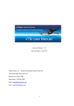
VEHICLE SINGLE FILAMENT CABLE HARNESS
DASHBOARD
ref. E
BRAKE
ref. P
FRONTSUSP
ref. AI
APX1
ref. A
DEMAND
ref. M
APX2
ref. B
LH
LIGHT SWITCH
ref. AD
PLATFORM 1
ref. D
INTAKE DUCT ECU
ref. D
INTAKE DUCT ECU SBK
ref. AO
ENGINE
ref. A
EX_VALVE
ref. AN
CHASSIS CAN-ETHERNET
GROUND 1
ref. G
ref. N
REGULATOR
ref. I
TONE WHEEL
CONTROL UNIT
ref. F
RH LIGHT SWITCH
ref. H
FRONT SPEED
SENS.
ref. AE
PURCHASE
ref. AC
LAMBDA
ref. L
CHASSIS
GROUND 2
ref. M
REARSUSP
ref. AF
TARGET
ref. Q
FUEL PUMP
ref. S
STARTER MOT.
ref. O
REAR SPEED SENS.
ref. R
LIGHT
ref. U
STARTER RELAY
ref. U
START.MOT.REL.CABLE
ref. V
LAMBDA RELAY PROTECTION RELAY
ref. AL
ref. Z
INJECTION RELAY
ref. AB
MAIN FUSES
ref. AA
MON - 28
SST 2015
Motorcycle assembly
ENGINE MULTIFILAMENT CABLE HARNESS
"VEHICLE"
CONN. MIL
ref. C
INJ1_1
INJ1_2
INJ1_3
INJ1_4
INJ2_1
INJ2_2
INJ2_3
INJ2_4
IGN CIL1
IGN CIL2
IGN CIL3
IGN CIL4
POIL MIN
RPM+
RPMGEAR POT
DBW1+
GND PWR
DBW2DBW2+
DBW1TPSRED2
TPS2
T AIR
T H20
TPSRED1
+INJ\IGN
TPS1
LOAD CELL
VREF1\5V
MGND PWR
GND ANA2
GND ANA1
GND PWR
+INJ\IGN
+INJ\IGN
M+
VREF3\5V
VREF4\5V
V12A
SET GEAR
GND
"LOAD CELL"
ref. AM
"SET GEAR"
ref. AH
"P_OIL_MIN"
ref. AL
"COIL1"
SUPERSEAL 3VF
ref. D
"COIL2"
SUPERSEAL 3VF
ref. E
"COIL3"
SUPERSEAL 3VF
ref. F
"COIL4"
SUPERSEAL 3VF
ref. G
"INJ1 LOW"
AMP 2VF
ref. H
"INJ2 LOW"
AMP 2VF
ref. I
"INJ3 LOW"
AMP 2VF
ref. L
"INJ4 LOW"
AMP 2VF
ref. M
"INJ1 UPP"
AMP 2VF
ref. N
"INJ2 UPP"
AMP 2VF
ref. O
"INJ3 UPP"
AMP 2VF
ref. P
"INJ4 UPP"
AMP 2VF
ref. Q
"T H20"
ref. R
"THROTTL 1"
TYCO 6VF
ref. S
"THROTTL 2"
TYCO 6VF
ref. T
"GEAR POT"
ref. AG
"SPEED SENSOR"
ref. AB
"T AIR"
2VF
ref. AC
"INTAKE DUCT MOT."
2VF
ref. AD
"GND ENGINE"
ref. AF
CABLES SIDE VIEW
INJ1-2-3-4 LOW/UPP
GEAR POT.
WIRE COLOR
Az = SKY BLU E
Bi = WH ITE
Ar = OR AN GE
G = YELLOW
Gr = GR EY
B = BLU E
M = BR OWN
N = BLAC K
R = R ED
R o = PIN K
V = GR EEN
Vi = PU R PLE
MON - 29
SST 2015
Motorcycle assembly
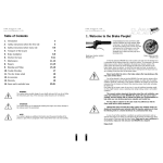
ENGINE SINGLE FILAMENT CABLE HARNESS
VEHICLE
ref. C
P_OIL_MIN
ref. AL
TEMP. H20
ref. R
GND ENGINE
ref. AF
INJ 4 LOW
ref. M
COIL 4
ref. G
INJ 2 LOW
ref. I
COIL 2
ref. E
GEAR POT
ref. AG
THROTT MOT 2 THROTT MOT 1
ref. S
ref. T
LOAD CELL
ref. AM
INJ 2 UPP
ref. O
SET GEAR
ref. AH
INJ 3 LOW
ref. L
INJ 1 LOW
ref. H
INJ 1 UPP
ref. N
INJ 4 UPP
ref. Q
AIR TEMP. SENS.
ref. AC
INTAKE DUCT MOT.
ref. AD
SPEED SENSOR
ref. AB
COIL 1
ref. D
MON - 30
COIL 3
ref. F
INJ 3 UPP
ref. P
SST 2015
Motorcycle assembly
CABLE HARNESS DEMAND
A
B
"DEMAND MASTER"
C
D
E
F
arancio
nero
giallo
A
B
"DEMAND SLAVE"
1
2
3
4
arancio
nero
C
D
verde
arancio
E
F
"DEMAND "
5
6
7
8
9
10
DEMAND CONNECTORS - CABLES SIDE VIEW
1
6
2
3
4
5
7
8
9
10
"DEMAND MASTER"
110
"DEMAND"
"DEMAND SLAVE"
210
Instrument panel
Matrix/RSS is the instrument panel of Aprilia Racing, which thanks to the wide LCD display and the
analogue speedometer allows a clear visualisation
of the engine and the parts of the information managed by the control unit APX2.
When the power supply to the electric circuit of the
vehicle is activated, wait at least 3 seconds, as the
entire electronic system performs the reset cycle.
When the instrument panel light will be on and
when the rpm indicator needle is firmly set to zero
rpm, it will be possible to start the engine..
Display
The instrument panel allows the visualisation of the information in two different windows:
MAIN: page always active during the normal operation of the motorcycle
PIT-LANE: is activated by pressing the BOX key on the LH push-button panel on the handlebar together
with the speed limitation strategy in Pit-Lane
MON - 31
Motorcycle assembly
MAIN PAGE
key:
1. GEAR - Display of the engaged gear (from 0 to
6). 0 the idle.
2. EB - Engine brake level. H: HIGH; L: LOW (see
PDA manual and section LEFT PUSH-BUTTON
PANEL for the correct engine brake management)..
3. MAP - Engine mapping selection (1: DRY; 2:
WET)
4. TC - TCS traction control level (from 0 to 7 - see
PDA manual parameter RIDER L)
5. In the lower part of the display is a series of
messages:
•
"Lap time" - Visualisation of the lap
time, for 60 seconds.
•
RBW ERR - Problems at the RBW system, or at the throttle bodies.
•
GAS ERR - The gas potentiometer
does not work.
•
TUN ERR - Any setting or implementation error of the gas, RBW, gear.
•
TC ERR - The inertial platform is disconnected or not mounted correctly.
•
E##: ## - 0..63. The specific error is indicated (consult the error table)
•
"NEUT" - with the system on (supplied
electric system) but the engine off indicates that the motorcycle is running.
Safety that avoids the start-up of the
engine until the gear is not put in the
idle position, with following message
cancellation.
•
"LAUNCH" - indicates active start strategy, is cancelled when exiting the strategy
NOTE
THE ERROR MESSAGES HAVE THE PRIORITY BEFORE
ALL OTHER MESSAGES.
MON - 32
SST 2015
SST 2015
Motorcycle assembly
PIT-LANE PAGE
key:
1. TW - Water temperature
2. PW - Water pressure (not active)
3. TC - TCS traction control level (from 0 to 7 - see PDA manual parameter RIDER L)
4. EB - Engine brake level H: HIGH; L: LOW (see PDA manual and section LEFT PUSH-BUTTON
PANEL for the correct engine brake management)
5. TOIL - Engine oil temperature (NOT AVAILABLE)
6. POIL - Engine oil pressure (NOT AVAILABLE)
7. PF - Fuel pressure (NOT AVAILABLE)
8. BAT - Battery voltage
9. MAP - Engine mapping (1: DRY; 2: WET - shown also with message on bottom of display)
10. CF - Fork stroke (NOT AVAILABLE)
11. CS - Shock absorber stroke (NOT AVAILABLE)
MON - 33
Motorcycle assembly
LED indicator
key:
1. ERROR ALARM LED - Led that indicates the
presence of errors
2. LED PIT LIMIT - Engaged "pit-limit" strategy
activation signal
3. LED n°6 - Not in use
4. GEAR SHIFT SIGNAL LED - Gear shifting signal LED, can be configured with PDA
Change serial push-button panel
The left push-button panel mounted on the standard motorcycle needs some easy modifications to
be used:
•
Remove the "TURN INDICATOR
LIGHTS CONTROL"
•
Remove the screws A and B
•
Open the block and remove the screws
C and D
MON - 34
SST 2015
SST 2015
•
Motorcycle assembly
Follow the wires of the push-button
panel to the connector and remove the
relative pins, except for the blue/black
that must be cut.
•
To extract the pin from the connector,
the tab must be pushed downward as
indicated in the figure and then removed from the connector pulling from
the cable side
•
Remove all the wires from the sheath and eliminate the push-button
•
Close the block again by refitting the screws A and B
The second operation to be made is the modification of the pin-out of the connector
•
Remove the WHITE and YELLOW/
BLACK wires from the 6-pole connector (or if of a different colour the ones
in the same position of the ones indicated in the figure)
•
Fit the two wires extracted in the 9-pole
connector inserting them from under in
the shown order
Thus modified the push-button panel, it is used for the following functions:
•
TRACTION CONTROL adjustment (TCS)
•
PIT LANE strategy activation
•
Rear light activation
•
ENGINE BREAKING strategy adjustment
MON - 35
Motorcycle assembly
Description left push-button panel
key:
1. PIT - Activation of the PIT LANE speed limiter press the lower push-button. With the activation of
the PIT-LANE strategy on the display appears the
page "INFO"
2. EB - Pressing the push-button applies an offset,
of fixed value in the control unit, to the ENGINE
BRAKING value set in the page STRATEGIES→ENGINE BRAKING of the PDA. The operation is also shown on the instrument panel: EB
=H (HIGH) sums a fixed offset in the control unit to
the value of the PDA page to increase also the engine brake EB =L (LOW) offset equal to engine
brake zero as shown in page ENGINE BRAKING
of the PDA
3. TCS - Regulates the TCS control intervention
level - to increase move the push-button to the
right; to reduce move the push-button to the left.
Corresponds to the parameter RIDER L page
STRATEGIES→TCS of the PDA
4. LIGHT - Rear light activation - rear push-button
MON - 36
SST 2015
SST 2015
Motorcycle assembly
Description right push-button panel
key:
1. RED PUSH-BUTTON- SYSTEM ACTIVATION
(HIGH) - pressing it to supply the electric system
of the motorcycle
2. MAP - ENGINE START-UP - After supplying the
electric system, pressing it starts the engine. MAP
GEAR - with the engine running, allows to select
one of the tow engine mappings available. On the
instrument panel appears: 1: for the DRY curve; 2:
for the WET curve;
MON - 37
INDEX OF TOPICS
PDA
PAL
SST 2015
PDA
Index:
1. INTRODUCTION
- FUNCTIONS OF THE KEYBOARD
- SYMBOLS IN THE DISPLAY
2. STRUCTURE OF THE PDA MENU
3. PDA PAGE DESCRIPTION
- FIRST PAGE
- MAIN MENU
SETTING
A. SETTINGS - GEAR
B. SETTINGS - GAS
C. SETTINGS - RBW
D. SETTINGS - SENSORS
E. SETTINGS - INERTIAL PLATFORM
F. SETTINGS - TYRE
G. SETTINGS - INTAKE DUCT
H. SETTINGS - EXHAUST VALVE
ENGINE
A. ENGINE - CURVE
B. ENGINE - IDLE RBW_SP
C. ENGINE - LAMBDA START
D. ENGINE - K_INJ
E. ENGINE - AIR PRESS SET
F. ENGINE - RPM LIMITER
G. ENGINE - INT. DUCT OPEN
MONITOR
PARAMETERS
A. PARAMETERS - GEAR - FLASH (GEAR SHIFT LED SETTINGS)
B. PARAMETERS - GEAR-SHIFT (GEAR SHIFT SETTINGS)
C. PARAMETERS - BEACON (BEACON SETTINGS)
D. PARAMETERS - LAP-SHIFT (BEACON SHIFTING)
E. PARAMETERS - VIRTUAL BEACON
F. PARAMETERS - SESSION (COMPETITION/CLASSIFIED SESSION SETTING)
G. PARAMETERS - PIT_LANE (PIT LANE)
H. PARAMETERS - WHEEL CIRCUMF (WHEEL CIRCUMFERENCE)
I. PARAMETERS - WHEEL_TEETH (TEETH FOR THE WHEEL SPEED DETECTION)
ERRORS
STRATEGIES
PAL - 39
PDA
SST 2015
A. STRATEGIES - TCS (TRACTION CONTROL)
B. STRATEGIES - ADAPTIVE_TCS (ADAPTIVE TRACTION CONTROL)
C. STRATEGIES - DISTANCE BASED (DISTANCE BASED CONTROLS MODIFICATIONS)
D. STRATEGIES - ENGINE BRAKING (ENGINE BRAKING CONTROL)
E. STRATEGIES - POWER REDUCT (POWER REDUCTION CONTROL)
F. STRATEGIES - WHEELIE CTRL (ANTI WHEELING CONTROL)
G. STRATEGIES - HTERRA
H. STRATEGIES - BACKLASH CTRL (ANTI-JERK CONTROL)
I. STRATEGIES - LAUNCH CTRL (ASSISTED LAUNCH CONTROL)
Introduction
The PDA is an interface between the user and the motorcycle ignition system. This allows to perform
operations on the motorcycle control unit, such as the visualisation or the control of parameters necessary for the motorcycle functioning like: gear threshold, throttle valve, errors etc. It is recommended
to connect the PDA to the motorcycle after the instrument panel has finished the reset procedure, when
the rpm indicator needle is firmly set to zero. At the end of the operations, before starting the engine,
disconnect the PDA. It may occasionally occur that, once the PDA is connected, incomprehensible
characters appear on its display; in this case turn off the panel, disconnect the PDA and repeat the
above described operation..
If during start-up the text "NO CAN CONNECTION" appears on the PDA display, it is necessary to set
the connection speed of the PDA with the motorcycle control unit. This usually occurs when a PDA is
used for the first time that was never used before.
PAL - 40
SST 2015
PDA
The setting of the connection speed of the PDA is as follows:
1. On the display appears "NO CAN CONNECTION";
2. Simultaneously press the keys "Shift" and "1 Home";
3. With the low arrow (key 9) go to "Settings" and press "Enter";
4. Press "Enter" when the item "CAN" appears;
5. When the item "BaudRt" appears, press the left arrow (key 4) and the value 1 M turns to 500 K;
6. At this point press the key "1 Home" until returning to the main menu, where the item "EXIT"
appears, using the low arrow (key 0) move to "EXIT" and press "Enter";
7. Once this is done, turn the system off and on again. If all these procedure are performed correctly,
the main screen of the system appears.
When connecting the PDA, a test of the internal functions will be performed on the motorcycle. On the
display appears for some seconds the following screen, after a moment followed by the Main menu
page or by the one with the errors, if present in the ECU
KEYBOARD USE
In this section the keyboard functions are shown
in detail.
The following figure shows the PDA keyboard.
PAL - 41
SST 2015
PDA
FUNCTIONS OF THE KEYS
key "1" (Home): Returns to the previous menu.
Key "2": Moves the cursor up.
Key "3" (PgUp): Returns to the previous page.
Key "4": Decreases the value
Key "5": Not used
Key "6": Increases value.
Key "9" (PgDn): Goes to the next page.
"Enter" Key: Confirm.
Key "0": Moves the cursor down.
"Shift" Key: Decreases value.
SYMBOLS IN THE DISPLAY
On the display the following symbols/icons can be found (in the following the corresponding explanations are indicated):
ICON LEGEND IN DISPLAY
1
2
3
Indicates that there is information on the next page.
Indicates that there is information on the previous page.
Indicates the line on which the cursor can be positioned. When flashing, it indicates the line on which
the cursor is positioned.
Structure of the PDA menu
In the following a short list of all functions available in the PDA.
PAL - 42
SST 2015
PDA
NOTE
THIS COULD VARY DEPENDING ON THE FIRMWARE VERSION.
-SETTINGS
•
GEAR
•
GAS
•
RBW
•
SENSOR
•
INERTIAL PLATFORM
•
TYRE
•
INTAKE DUCT
•
EXHAUST VALVE
-ENGINE
•
CURVE
•
IDLE RBW SP
•
LAMBDA START
•
K INJ
•
AIR PRESS SET
•
RPM LIMITER
•
INT. DUCT OPEN
-MONITOR
•
Real time view
-PARAMETERS
•
GEAR-FLASH
•
GEAR-SHIFT
•
BEACON
•
LAP SHIFT
•
VIRTUAL BEACON
•
SESSION
•
PIT LANE
•
WHEEL CIRCUM
•
WHEEL TEETH
-ERRORS
•
Shows possible errors
-STRATEGY
•
TCS
•
ADAPTIVE_TCS
PAL - 43
SST 2015
PDA
•
DISTANCE BASED
•
ENGINE BRAKING
•
POWER REDUCT.
•
WHEELIE CTRL
•
HTERRA
•
BACKLASH CTRL
•
LAUNCH CTRL
Description PDA pages
First page
As previously anticipated, when connecting the
PDA, a test of the internal functions is carried out
to search for possible errors.
•
If there are no errors in the memory, the
first page, as an example, will be the
following:
SW: indicates the engine control firmware version.
TYPE: type of motorcycle used in this configuration.
CFG: the name of the engine configuration in the control unit.
NOTE
PRESSING ANY KEY ENABLES THE ACCESS TO THE MAIN MENU
•
If errors are detected during the initial
test, a different page with a report of
each error will appear. This is the "ERRORS PAGE". The abbreviation ERR
appears on the right of the channel that
caused the malfunction. See example:
The second line at the top shows the different operations that can be made:
•
ENT = Cl Indicates that pressing the ENTER key cancels the error of the selected line
•
7 = Cl Indicates that pressing the key 7 cancels contemporary all errors in the memory
•
8 = Ch Situation update of errors in control unit
If the error persists after turning the system off and on again , go to the "SETTING PAGE" and check
the parameters related to the errors/ signal/s.
PAL - 44
SST 2015
PDA
NOTE
ONCE THE ERROR IS RESOLVED, BY PRESSING THE KEY "ENTER" IT IS POSSIBLE TO RETURN TO THE MAIN MENU
MAIN MENU
From the initial page, press any key to go to the MAIN MENU consisting of:
1. SETTINGS
2. ENGINE
3. MONITOR
4. PARAMETERS
5. ERRORS
6. STRATEGY
To access any of these items, just move the cursor to the desired line and press "ENTER".
NOTE
IT IS ALWAYS POSSIBLE TO RETURN TO THE "MAIN MENU" PRESSING THE KEY "HOME"
Settings
Below a detailed explanation of the different options:
These settings are regarding the essential sensors or devices and will be set up before being
able to use the motorcycle:
A. SETTINGS - GEAR
B. SETTINGS - GAS
C. SETTINGS - RBW (to be performed first)
D. SETTINGS - SENSOR (only for systems supplied with Data acquisition)
E. SETTINGS - INERT.PLATFORM
F. SETTINGS - TYRE
G. SETTINGS - INTAKE DUCT
H. SETTINGS - EXHAUST VALVE
NOTE
THE FIRST OF THE CALIBRATIONS TO BE DONE IS THE ONE OF THE THROTTLE VALVES
"RBW", OTHERWISE, WITHOUT THE CORRECT SETTINGS, THE ENGINES OF THE THROTTLE
VALVE COULD BE FORCED ON THE END-STOP AND RISK TO DAMAGE IT
A. SETTINGS - GEAR
This sub-menu is divided in:
1. GEAR THRESHOLD
2. GEAR RATIOS
3. GEAR TYPE (DO NOT USE)
1. SETTINGS - GEAR - GEAR THRESHOLD
In this page it is necessary to set-up the gear potentiometer thresholds for each gear, so the ECU can
recognise the correct ratio inserted. Also this is a very important operation for the correct operation of
PAL - 45
PDA
SST 2015
the motorcycle, therefore it is ESSENTIAL to set them every time operations on the gear or on the
corresponding potentiometer are made. The page that appears when pressing [ENTER], when the
cursor is placed on "GEAR TUNING" is the following:
NOTE
THE VALUES AS IT CAN BE SEEN DO NOT FOLLOW A MATHEMATICAL ORDER, BUT THIS IS
ABSOLUTELY NORMAL. THE ABOVE INDICATED VALUES CAN BE CONSIDERED FOR REFERENCE.
"cnt val" indicates the value in "Real Time" (of in count) of the potentiometer. The values on the right of
each gear are the ones saved in the control unit. When entering this page, the value related to the 1st
gear will blink and indicate that it is ready to be saved by pressing the key "ENTER".
Now the first gear must be engaged mechanically, and by pressing "ENTER" the value in count ("cnt
val") of the first gear will be saved in the ECU.
At this point the value in ("cnt val") and the value saved at the right of 1↑INS related to the first gear
must match.
By pressing the key "0" it will move to the value in count of the second 2nd gear, the 2nd gear will be
engaged mechanically and as it was made previously, the "ENTER" is pressed.
Repeating this procedure for each gear it will be necessary to set-up the values of the gear for all the
gears up to the 6th gear.
The idle is saved automatically.
Once all the thresholds of the gear are set-up, check by engaging each gear mechanically that the value
"cnt val" and the related saved value for each gear match.
Press [Home] to return to the menu GEAR SETTING
PAL - 46
SST 2015
PDA
2. SETTINGS - GEAR - GEAR RATIOS
In this page the Ratio of the Primary drive (P),
the Final ratio (F) and the Gear ratio for each
gear (1-6) must be set-up, keeping in mind that:
1: The ratio of the primary drive remains fixed
and shall then not be modified.
2: The final ratio (pinion / rim) depends on the
user preferences and is inserted time by time.
3: The ratio of each gear depends on the type
of gear inside the engine.
4: A wrong setting of the gear ratio can affect
the correct operation of the TCS.
The values of this table can be considered as reference for the engine version 2015 RR and RF
and are not modified if the gearboxes remain the standard ones.
P: Primary gear ratio
F: Final ratio
1-6: Gear ratio
To move the cursor between Z1 and Z2 use the keys [2] and [0], and the same to pass from P (Primary)
to F (Final). Once the cursor is in the desired positioned, a new value can be set-up using the keys [4]
and [6].
Press [Home] to return to the menu GEAR SETTING
3. SETTINGS - GEAR - GEAR TYPE
This menu is not used, The default values (Reduct: No for all gears) set in this menu are not modified
in order not to compromise the correct functioning of the motorcycle.
B. SETTINGS - GAS
In this page it is necessary to perform the calibration (tuning) of the throttle control (Demand), storing in the control unit (ECU) a reference to the
throttle when it is fully closed and when it is fully
open. The page appears by choosing in the menu
SETTINGS the option "GAS". It must be kept in
mind that because of safety reasons the motorcycle provides 4 potentiometers (Gas/Gas-Aux and
PAL - 47
SST 2015
PDA
Gas2/Gas2-Aux) contained in the same box (Demand). All four potentiometers are set in the ECU
with the one procedure shown below.
To set-up the position to closed throttle:
•
Put the cursor to 0% (blinking)
•
Leave the throttle grip in rest position
(0%)
•
Press the [ENTER] key
In this way we have set the count to 0%, the values
Cnt must correspond to the saved relative values
at gas 0.
To set-up the position to fully open throttle:
•
Put the cursor to 100% (blinking)
•
Keep the throttle grip in completely
open position (100%);
•
Press the [ENTER] key
In this way we have set the count to 100%, the
values Cnt must correspond to the saved relative
values at gas 100.
Moving with the key [PgUp (3)] e [PgDn (9)] at the
corresponding page the second group of gas potentiometers (Gas2) is accessed, where the values that were automatically saved during the
setting of Gas1 can be displayed. It not necessary
to repeat the operation.
The values shown in this table can be considered for reference
NOTE
THE VALUE IN "COUNT" OF GAS1 MUST BE HIGHER THAN 810 "COUNT" IF THE THROTTLE IS
AT 0%, AND LOWER THAN 3265 "COUNT" WHEN THE THROTTLE IS AT 100%. IF NOT DONE,
IT IS NECESSARY TO ADJUST THE POSITION OF THE ADJUSTERS OF THE THROTTLE CABLES.
If you make any errors during the calibration, on the instrument panel appears TUNING ERROR
and an error message (GAS TUN:ERR) in the page ERRORS appears on the PDA.
C. SETTINGS - RBW
NOTE
PAL - 48
SST 2015
PDA
THIS SETTING MUST BE CARRIED OUT AS SOON AS POSSIBLE AFTER STARTING THE SYSTEM
This page allows the automatic setting of the values of the Ride by Wire.
The operation is made by only pressing the key [7],
the control unit will register the values corresponding to the minimum and maximum of the throttle
valves opening of the throttle bodies 1 (Rear) and
2 (Front) closing and opening them automatically.
(The above indicated values can be considered for
reference). This procedure takes about 20 seconds.
With this operation are set the values of the two
throttle bodies. For the throttle body 2 (Front) it is
possible to verify the setting values by moving with
the key [PgDn (9)] in the page FARF2.
The values shown in this table can be considered for reference.
If you make any errors during the calibration, on the instrument panel appears RBW ERROR and
an error message (RBW TUN:ERR) in the page ERRORS appears on the PDA
D. SETTINGS - SENSORS
The entire sub-menu "Sensor" is about the systems with Data acquisition and is treated separately.
E. SETTINGS - INERTIAL PLATFORM
The inertial platform must be fitted as in the figure and the setting from the PDA must be as follows:
MOUNT2011:1
NOTE
1: MODIFYING THIS SETTING CAUSES INCORRECT FUNCTIONING OF THE TCS.
2: MOVING AND/OR MODIFYING THE POSITION OF THE INERTIAL PLATFORM CAUSES INCORRECT FUNCTIONING OF THE TCS
PAL - 49
PDA
SST 2015
F. SETTINGS - TYRE
This operation allows to set the wheel parameters in case of different weather conditions:
G. SETTINGS - INTAKE DUCT
Command not enabled
H. SETTINGS - EXHAUST VALVE
Command TUNING Exhaust valve. Not present in the motorcycle versions SST. DO NOT USE
Engine
In the menu' "ENGINE" are the following sub-menus:
A. ENGINE - CURVES
B. ENGINE - IDLE RBW SP
C. ENGINE - LAMBDA START
D. ENGINE - K INJ
PAL - 50
SST 2015
PDA
E. ENGINE - AIR PRESS SET
F. ENGINE - RPM LIMITER
G. ENGINE - INT. DUCT OPEN
A. ENGINE - CURVE
Inside the control unit, an engine curve for the dry
track conditions (DRY) and a curve for the wet
track conditions (WET) are pre-set. This option, by
acting on the push-buttons [4] and [6] of the PDA,
allows to select the desired one.
B. ENGINE - IDLE RBW_SP
This parameter indicates the opening % of the
throttle valve at idle speed. Modifying this value it
is possible to raise or lower the engine at idle,
which should remain within 2300-2500 Rpm.
The modification must be max +\- 0.2% each time.
C. ENGINE - LAMBDA START
key:
[rpm]: indicates the engine speed in rpm, at which
the lambda probe (if present) is activated. The activation of the lambda probe is also done when the
time strategy (described below) is disabled.
[s]Enable: 0 disables the lambda activation control with "time" strategy. 1 enables the lambda
activation control with "time" strategy.
[s]Start: delay seconds for the activation of the
lambda after verifying the "rpm" condition
[s]Stop: time period till the lambdas turn off
PAL - 51
PDA
D. ENGINE - K_INJ
Adjustment: 50....150
Recommended parameter 100 (%) for each cylinder.
NOTE:
Value = 100 % : to use the set value of the map
Value > (over) 100 % : to increase the injection
time (reduction of the stoichiometric ratio A\F)
Value > (under) 100 % : to decrease the injection
time (increase of the stoichiometric ratio A\F)
NOTE
THESE VALUES ARE MULTIPLIER COEFFICIENTS % AND
ALLOW TO LEAN OR RICHEN THE CARBURATION OF
EACH CYLINDER.
IF FOR EXAMPLE ON CYL 1 IS WRITTEN: 105 IT WILL
GROW 5% COMPARED TO THE BASIS MAP THE CYLINDER NUMBER 1, IF YOU WANT TO LEAN 5% WRITE 95%
INSTEAD.
THIS TYPE OF MODIFICATION IS A VERY DELICATE OPERATION, AS IT CAN CAUSE LOSS OF PERFORMANCE
OR EVEN IRREVERSIBLE DAMAGE TO THE ENGINE.
THEREFORE IT SHOULD ONLY BE MODIFIED BASED ON
THE READING OF THE LAMBDA PROBE (IF INSTALLED).
E. ENGINE - AIR PRESS SET
key:
[mbar]: This page allows to indicate the air press
in the circuit to the system, so based on an algorithm it can make the necessary carburetion corrections.
[Speed Min]: This is the minimum speed to above
which, through an algorithm, will be calculated the
"virtual" atmospheric pressure such as to make the
appropriate changes to the injection timing depending on the speed. (This parameter does not
need any modification).
PAL - 52
SST 2015
SST 2015
PDA
F. ENGINE - RPM LIMITER
This page allows to set the value in Rpm of the
Rpm limiter for each gear, the recommended value
not to be exceeded for the version SST is 14000
Rpm.
Exceeding this value leads to more frequent
maintenance intervals and reduces the mechanical reliability.
G. ENGINE - INT. DUCT OPEN
This page allows to set-up the opening parameters
of the duct with adjustable height of the throttle
bodies.
key:
Thr%: indicates the throttle threshold value after which the intake duct opens, while H is the related
hysteresis
THR%: 90.0 DO NOT MODIFY
H = 5.0 DO NOT MODIFY
RPM: indicates the engine rpm value after which the intake duct opens, while H is the related hysteresis.
RPM = 12800
H = 1000 DO NOT MODIFY
The intake ducts only open when the two conditions of rpm and throttle are verified
PAL - 53
PDA
SST 2015
Monitor
This page allows to display in "real time" the essential parameters of the motorcycle like rpm, throttle,
engaged gear etc. and it can be navigated through the various menus using the key arrows [2] and [0],
or [PgUp (3)] and [PgDn (9)].
For some items it is possible to read the correspondent in Counts pressing the key ENTER
Parameters
A. PARAMETERS - GEAR-FLASH
B. PARAMETERS - GEAR-SHIFT
C. PARAMETERS - BEACON
D. PARAMETERS - LAP-SHIFT
E. PARAMETERS - VIRTUAL BEACON
F. PARAMETERS - SESSION
G. PARAMETERS - PIT LANE
H. PARAMETERS - WHEEL CIRCUM
I. PARAMETERS - WHEEL TEETH
A. PARAMETERS - GEAR - FLASH (GEAR
SHIFT LED SETTINGS)
This page allows to set-up the rpm speed for each
gear, at which the gear shift led on the instrument
panel lights up.
Usually it is recommended to set them to 500/600
Rpm before the limiter.
(E.g. Lim. = 13800)
PAL - 54
SST 2015
PDA
B. PARAMETERS - GEAR-SHIFT (GEAR SHIFT
SETTINGS)
This page allows to set-up the different parameters
related to the Electronic Gear Shift system.
NOTE
THE VALUES SHOWN IN THE FIGURE ABOVE MUST BE CONSIDERED AS INDICATIVE
key:
SensType: gear shift typology setting
•
Set = With sensor on mechanical gear rod (Standard)
•
OnlyPot = With exclusive use of the gear potentiometer (No SST)
•
Load = With use of a load cell supplied separately
The potentiometer of the gear and the mechanical sensor on the rod of the gear are always installed
on the motorcycle, while the fitting of the load cell is optional and also allows assisted downshift (blipper
\kicker strategy).
The below parameters are to be considered only in presence of the load cell fitted on the gear
lever
LoadZero: Load cell reset. With the load cell in rest position (not loaded) press the key [ENTER] to
reset the value of the loaded load cell
ThrUP and ThrDW: they allow to reset the cell and to set the thresholds, expressed in Newton, of
system intervention, selecting the loads both in gear shift as well as downshift.
Usually the thresholds are the following:
With gear RACING (1st gear up)
ThrUP (N) : 120 = about 12 Kg
ThrDW (N) : -80 = about 8 Kg
With road gear (1st gear down)
ThrUP (N) : -120 = about 12 Kg
ThrDW (N) : 80 = about 8 Kg
PAL - 55
SST 2015
PDA
C. PARAMETERS - BEACON (BEACON SETTINGS)
TYPE: "Sector" if only one activator exists (usually
on the beacon line) or "Lap" in presence of two
transmitters on the beacon line and various transmitters in correspondence of various circuit sectors.
ACTIVE_LEV: is relative to the type of electric signal supplied by the receiver, HIGH = high and
LOW = low.
SOURCE:
•
SINGLE : usable option (beacon trigger single signal)
•
WIDTH : option not usable
•
CAN : option not usable
D. PARAMETERS - LAP-SHIFT (BEACON SHIFTING)
This setting allows, if a beacon is installed, to virtually move the position of the transmitter regarding its
physical position by entering a value expressed in meters.
Once the signal is received, a meter counter starts, and as soon as the set value is reached it triggers
the lap cut on the motorcycle.
Usually this value is left at zero and must always and only be positive.
E. PARAMETERS - VIRTUAL BEACON
Setting not used by the SST system
F. PARAMETERS - SESSION (COMPETITION/
CLASSIFIED SESSION SETTING)
CAUTION
SETTING USUALLY SET TO ON, IS RELATED TO THE ACTIVATION OF A DIAGNOSTIC SYSTEM THAT TURNS OFF
THE ENGINE WHEN THE OIL PRESSURE IS MISSING. THIS
SERVES TO PROTECT THE ENGINE AND RIDER SAFETY.
SETTING THIS OPTION TO OFF, SUCH SYSTEM IS DEACTIVATED BECAUSE OF THE RISK AND DANGER TO THE
USER.
PAL - 56
SST 2015
PDA
G. PARAMETERS - PIT_LANE (PIT LANE)
These parameters allow to set the maximum travel
speed of the motorcycle in the pit lane, as in the
regulation.
SPEED_LIM: speed in Km/h above which the limiter intervenes
LENGTH: is the length in meters beyond which the
system is disabled.
CAUTION
IN EVERY CASE THE SYSTEM IS ONLY ACTIVE IN FIRST
GEAR - WHEN THE SECOND GEAR IS ENGAGED THE
CONTROL DISENGAGES AUTOMATICALLY.
H. PARAMETERS - WHEEL CIRCUMF (WHEEL
CIRCUMFERENCE)
This page allows the modification of the circumference values of the F (front) and R (rear) wheels.
The parameter "USE CLF" MUST REMAIN
STRICTLY SET TO "YES".
The values in millimetres F and R are fix, but it is
possible to set different wheel circumference values by changing the respective Gain as following.
The final value of the circumference will be given
by 1900X G (1.000) and 2064X G (1.00).
EXAMPLE:
Desired front wheel circumference value to be
set to 1950 mm;.
Value G (relative gain to be set) = Desired value
1950: Fix value (F)1900= 1.026
These settings are essential for the correct
functioning of the TCS.
I. PARAMETERS - WHEEL_TEETH (TEETH
FOR THE WHEEL SPEED DETECTION)
Do not modify the values in the figure.
PAL - 57
PDA
SST 2015
Errors
This important page is related to the display of possible errors in the control unit and is displayed at
system start, if there are errors.
The possible items to be displayed are:
SPEED_FR:ERR Front speed sensor reading error
SPEED_RR:ERR - Rear speed sensor reading error
GAS TUN:ERR Error during calibration of the throttle control
POIL LOW:ERR Oil pressure too low
RBW TUN ERR: - Error during calibration of RBW (driven throttle valve)
INPLAT_CAN ERR: - Inertial platform error (disconnected or damaged)
TCS ERR: - TCS error (only verified after a drop)
VBATT ERR: - Error related to a too low battery voltage (the error can be verified also after a start-up
with empty battery)
GAS ERR: - Error on the gas potentiometer reading
GAS AUX ERR: - Error on the AUX gas potentiometer reading
THROT1 ERR: - Throttle valve 1 potentiometer error (REAR BANK)
THR1 AUX ERR: - Throttle valve 1 AUX potentiometer error
TROT2 ERR: - Throttle valve 2 potentiometer error (FRONT BANK)
THR2 AUX ERR: - Throttle valve 2 AUX potentiometer error
Once the cause of the error is identified it can be deleted from the memory going with the arrows to the
line containing the error and pressing the key "ENTER".
It is possible, in case of more errors, to delete all of them at the same time by pressing the key "7".
When the cause of the error was resolved the error page results empty when turning the system off and
on again.
Strategies
In this sub-menu all the motorcycle control systems are gathered together:
A. STRATEGIES - TCS
B. STRATEGIES - ADAPTIVE_TCS
C. STRATEGIES - DISTANCE BASED
D. STRATEGIES - ENGINE BRAKING
E. STRATEGIES - POWER REDUCT.
F. STRATEGIES - WHEELIE CTRL
G. STRATEGIES - HTERRA
H. STRATEGIES - BACKLASH CTRL
I. STRATEGIES - LAUNCH CTRL
PAL - 58
SST 2015
PDA
A. STRATEGIES - TCS (TRACTION CONTROL)
This page allows to set the parameters for the TCS
management. There are two parameters that can
be configured by the user:
RIDER L: (SELECTABLE LEVEL BY THE RIDER)
Indicates the traction control value set-up regarding a scale from 0 to 7.
0 equivalent to Turn off the system and 7 is the maximum possible control.
Usually it is set to 4.
This value, which is also displayed on the instrument panel, can be modified by the rider through the
push-button panel on the left semi-handlebar, depending on the track conditions and the rider preferences.
Usually it is recommended to act only to increase the TCS level, as reducing the system action this can
be dangerous.
RIDER L 0 - OFF
RIDER L 1 - Minimum level TCS
RIDER L 4 = TCS Standard level (dry track)
RIDER L 7 - Maximum level TCS
NOTE
PLEASE REMIND THAT PUTTING THIS VALUE TO 0 (ZERO) IS EQUIVALENT TO COMPLETELY
TURNING OFF THE SYSTEM. HOWEVER, THE TCS ACTIVATES AUTOMATICALLY OVER 120
KM/H AND TURNS OFF UNDER 40 KM/H.
LEVEL: (TCS GENERAL OFFSET LEVEL)
This parameter allows to set an offset on the value RIDER L ("RIDER LEVEL") allowing to increase or
reduce the general control value if also the maximum level (7) is not sufficient, e.g. at wet track.
Reducing the value "LEVEL" will increase the extent of the control
This value comes together with "RIDER L", and is set as follows:
LEVEL
LEVEL
0
-0.5
RIDER L
4
5
(STANDARD DRY TRACK)
(STANDARD WET TRACK)
Obviously these will be start values, and based on the track conditions or the rider preferences, the
level "RIDER_L" can be modified with the push-button panel on the handlebar.
SLIP1_C:
This parameter allows to modify the slip target. The modification of the parameter intervenes on the
slope of the offset line on the value RIDER L ("RIDER LEVEL").
PAL - 59
SST 2015
PDA
This value can variate inside the interval -0.015 and +0.015. For negative values the extend of the
control increases for the positive values instead reduces.
B. STRATEGIES - ADAPTIVE_TCS (ADAPTIVE
TRACTION CONTROL)
This function allows to activate an "Adaptive" traction control system, capable to adjust automatically depending on the track conditions, also in dry/
wet type variations.
The screen is as follows:
The set values are:
•
EN: 0-1 Adaptive system (Enable)
•
R_ATSTART: 0-1 (Reset values at each output)
•
RTS : manual reset of the values
The values 0 is equivalent to "OFF", while the value 1 means "Enable"
Usually these two values are set to 1 (Enable) and it is recommended not to modify them, while the
values "Of" and "Si are written by the control unit and cannot be modified.
C. STRATEGIES - DISTANCE BASED (DISTANCE BASED CONTROLS MODIFICATIONS)
This system allows to modify different parameters,
like TCS, Engine brake etc. in precise points of the
path.
To do so, the system needs a beacon that divides
the laps on the beacon lane, and a data acquisition
system to allow to exactly identify the path points
where to intervene.
If there is no beacon and Data acquisition system that allows to exactly know where the system must intervene, it is recommended to
leave all distance based values at ZERO as set
by Aprilia Racing, in order to avoid involuntary
interventions.
Schematically the system has 25 sectors identified
by a inlet threshold (Ms) and an output threshold
(Me) expressed in meters.
For each sector it can be varied:
PAL - 60
SST 2015
•
TCS (Traction control)
•
WHEELCTR (Anti wheeling control)
•
ENG BRAK (Engine brake)
•
PWR REDU (Engine reduction)
•
PREV PWR (Preventive engine reduc-
PDA
tion)
key:
1. Lock is disengaged
2. Lock Engaged
3. Value to be modified
4. TRACTION CONTROL
5. ANTI WHEELING CONTROL
6. ENGINE BRAKING
7. ENGINE POWER REDUCTION
8. Parameter correction 1
9. Set a value to be added to the parameter LEVEL
of the page STRATEGIES→TCS with variation
step of +/-0.1
10. Set a value to be added to the parameter
WC_COEFF of the page STRATEGIES - WHEELIE CTRL. Set variation step to +/-100
11. Set a value to be added to the engine braking
values of the page STRATEGIES - ENGINE
BRAKING. Refer to the description of the page later in the manual for the maximum allowed variation
interval.
12. Set a value to be added to the values of the
page STRATEGIES - POWER REDUCT. Refer to
the description of the page later in the manual for
the maximum allowed variation interval.
13. Parameter correction 2
14. Increase or reduce the value SLIP1_C of the
page STRATEGIES - TCS with variation step of
+/-0.01
15. Set a value to be added to the parameter
OFF_V of the page STRATEGIES - WHEELIE
CTRL. Set variation step to +/-10
PAL - 61
PDA
16. Not used, the parameter must be set to 0.
17. Not used, the parameter must be set to 0.
18. Start value Block in metres
19. End value Block in metres.
D. STRATEGIES - ENGINE BRAKING (ENGINE
BRAKING CONTROL)
This page allows to set the Engine brake values
expressed in [Newton] for each gear:
En = 1 Engine brake strategy ENABLED.
En = 0 Engine brake strategy DISABLED.
It is recommended not to modify this parameter and to start with the engine brake level as
indicated by the table above, to then modify
them depending on the rider and circuit needs.
It might be necessary to deactivate the Engine
brake ONLY for the workbench tests, but make
sure to activate it again for the track use of the
motorcycle.
The interval of allowed values for the engine braking varies if the dry (DRY) or wet (WET) curve is
used
key:
1. Increases Engine Brake
2. Reduces engine brake - Minimum settable engine brake level
3. Recommended start value
4. Increases engine brake - Maximum settable engine brake level
E. STRATEGIES - POWER REDUCT (POWER REDUCTION CONTROL)
PAL - 62
SST 2015
SST 2015
PDA
This function allows to reduce the engine power to
adjust it to the track conditions.
Usually this is used in the first gears (1st-2nd-3rd)
to avoid excessive grip loss or wheeling to completely open throttle.
Avoid using this function in the higher gears
(4th-5th-6th) in order not to loose engine performance.
Obviously the standard value is set to Zero, but
depending on the needs it can be reasonable to
bring it to a maximum of 50-60.
However setting the power reduction to 100 does
not mean to completely cut off the engine power,
but reduce it of the maximum granted, regarding a
table inserted in the control unit.
key:
1. Maximum Reduction=Minimum Power
2. Maximum Power (No Reduction)
3. Minimum Power (Maximum Reduction)
F. STRATEGIES - WHEELIE CTRL (ANTI WHEELING CONTROL)
PAL - 63
PDA
SST 2015
This page is related to the anti wheeling system adjustment parameters (WHEELIE CTRL).
The values shown in the table can be considered for reference.
The available items are the following:
ENABLE: Activates the system if set to 1, while
when set to 0, the system is disconnected.
It is recommended to leave this parameter to 1
for the track use.
OFF-V: This parameter is a threshold value, compared to the zero standard, set in the control unit
and expressed in °/sec of motorcycle wheeling
(pitch up). When this value is negative (-20, -30
etc..) then the system will intervene by cutting off
the power.
But increasing the value (e.g.: +10, +20 etc..) the
extent of the intervention of the system will decrease.
key:
1. Maximum Force
2. Reference
3. Minimum Force
WC_COEFF: (ANTI WHEELING CONTROL COEFFICIENT)
This parameter basically represents the torque limit transmitted to the wheel, above it the power will be
cut off.
As this torque depends, other than on the engine, on the total transmission ratio and then on the engaged gear, it can be decided to intervene e.g. on the first gears and not on the others, as following:
1000 -1100 = only 1st gear
1000 = 1st and 2nd
800 = 1st, 2nd and 3rd (basic set up)
600 = 1st, 2nd, 3rd and 4th
Increase this value (e.g. 100, 200) to have less anti wheeling control to the other gears (3rd, 4th, 5th
6th), or reduce it (e.g. -100, -200) to have more anti wheeling control to the other gears (3rd, 4th, 5th
6th).
PAL - 64
SST 2015
PDA
POWER_RED (POWER REDUCTION during the wheeling)
This value indicates the percentage extent (%) of the maximum power reduction during the intervention
of the anti wheeling system.
As previously described for the "POWER REDUCTION", also in this case the power reduction value is
not absolute, but percentage regarding a table in the memory of the ECU.
The following parameters LAU.oFF-V, LAU.COEFF, LAU P_RED refer all to the anti wheeling strategy
relative to the Launch control. For all settings of the above mentioned parameters, see the general anti
wheeling parameters
STRATEGIES - WHEELIE CTRL
G. STRATEGIES - HTERRA
Strategy not used by the SST system
H: STRATEGIES - BACKLASH\ANTIJERK CTRL (ANTI-JERK CONTROL)
This function is related to the power control during the first throttle opening phase, or when all
transmission clearance is recovered.
Basically the possibilities of adjustment are the following:
ENABLE/TYPE:
•
0= OFF
•
1= STD
•
2= EVO3 (Last pre-set version)
It is recommended to leave option 2 set.
I. STRATEGIES - LAUNCH CTRL (ASSISTED LAUNCH CONTROL)ENABLE: ON
This option allows the enabling or not of the assisted launch system.
The system is automatically activated when the motorcycle has a speed under 10Km/h and the strategy
"Pit-Lane" is disabled. On the instrument panel will be displayed the text "LAUNCH".
This system limits the maximum rotational speed at start, even if the throttle is completely open, and
will automatically turn off 3 seconds after start; in any case the strategy is disabled after engaging the
second gear.
It is recommended to leave the system in position ON as by the basic set-up.
PAL - 65
INDEX OF TOPICS
PRELIMINARY PROCEDURES
AND CALIBRATIONS
PRO
SST 2015
PRELIMINARY PROCEDURES AND CALIBRATIONS
Index:
PRELIMINARY PROCEDURE
- BATTERY
- PHONIC WHEEL SPEED SENSORS
CALIBRATION
- GEARBOX
- GAS
- RBW
- GENERIC SENSORS
- SUSPENSION SENSORS
- AIR PRESSURE
- GEARBOX LOAD CELL (OPTIONAL)
The following preliminary procedures are necessary so that the use of the motorcycle is safe both for
the driver and for the motorcycle. The calibrations are also important so that there are no anomalies or
problems when using the motorcycle.
Preliminary operations
After the preliminary procedure to be adopted at each motorcycle start
BATTERY
•
Check the zero load voltage of the battery which must be between: 12.8V < V battery <
13.7V
•
If the battery is empty, before performing any calibration, it is essential to proceed loading
the battery, so that then each calibration has a positive result.
PHONIC WHEELS SPEED SENSORS
•
It 'important to check the distance between the ends of the speed sensor and the teeth of
reading the phonic wheel (Gap).
•
The measurement must be as follows: 1.0 mm < GAP < 2.0 mm
GEARBOX
•
Check and calibration gears threshold
•
Check gear ratio and final ratio (pinion/crown)
•
Gear coupling. Set ALWAYS to "NO"
NOTE
PRO - 67
PRELIMINARY PROCEDURES AND CALIBRATIONS
SST 2015
THESE OPERATIONS MUST ALSO BE PERFORMED IF ANY CHANGE TO THE GEAR WAS MADE
(GEAR RATIO, GENERAL CHECKS OR AFTER FALLS).
GAS
•
Reset gas 0 with throttle control (demand) in closed position
•
Reset gas 100 with throttle control (demand) in fully closed position
NOTE
THESE OPERATIONS MUST ALSO BE PERFORMED IF ANY CHANGE TO THE THROTTLE CONTROL OR AFTER FALLS WAS MADE.
RBW
•
Calibrate the throttle bodies opening
NOTE
THIS OPERATION MUST BE PERFORMED WHEN THE AIRBOX IS REPLACED OR AFTER FALLS.
GENERIC SENSORS
•
FRONT SUSPENSION
•
REAR SUSPENSION
•
FRONT BRAKE SENSOR Reset the visualisation in real time of the front brake system
pressure with brake lever in rest position
•
REAR BRAKE SENSOR The rear brake system pressure is not acquired
•
OIL PRESSURE The engine oil pressure is not acquired.
•
OIL TEMPERATURE The engine oil temperature is not acquired
•
FUEL PRESSURE The fuel pressure is not acquired
•
FUEL TEMPERATURE The fuel temperature is not acquired
•
AIR PRESSURE
•
AIR TEMPERATURE Intake temperature from the engine, no operation to be performed
•
WATER TEMPERATURE Water temperature, no operation to be performed
CAUTION
IN THE PDA PAGES RELATIVE TO THE SENSORS ABOVE NEVER MODIFY THE DEFAULT VALUES OF THE PARAMETERS X1,X2,Y1,Y2
PRO - 68
SST 2015
PRELIMINARY PROCEDURES AND CALIBRATIONS
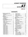
SUSPENSION SENSORS
FRONT SUSPENSION
The image below shows the correct assembly of
the front suspension motion sensor. The length
measured from the sensor is the distance between
the lower table of the lower plate and the rotating
centre of the front wheel.
For the correct calibration of the motion sensor the
motorcycle must be lifted at the front with a stand,
so that the front wheel is not in contact with the
ground. Then press the front wheel with the foot in
order to obtain the maximum extension of the front
fork. The motorcycle must remain in this position
until the calibration procedure is completed. In this
position measure with a metric device, take the
measure between the two above mentioned points
and correct the measure "L" (length) on the PDA
in the page SETTING>SENSORS>SUSP
FRONT. Then modify the offset value so that the
measure that is read in real time is the same as of
"L".
key:
1. Value "L_fork" in millimetres
2. Offset value
3. "Value" parameters
•
Complete the value "L_fork" in millimetres
•
Modify the offset value until the "value" parameters (in real time) turn it to "L_fork"
CAUTION
DO NOT MODIFY THE DEFAULT VALUES OF THE PARAMETERS X1,X2,Y1,Y2
PRO - 69
PRELIMINARY PROCEDURES AND CALIBRATIONS
SST 2015
REAR SUSPENSION
•
The following image shows the correct
mounting of the motion sensor of the
rear suspension.
•
For the correct calibration of the motion
sensor the motorcycle must be lifted at
the rear with a stand, so that the rear
wheel is not in contact with the ground.
Completely loosen the bolt fixing the
shock absorber in the upper part, in this
condition it will be in "neutral" position.
This is the condition to effect the measurement of the centre to centre distance of the shock absorber with a
metric device. This measurement must
than be shown at the item "L" in the
page "SUSP REAR"
key:
1. Value "L_Shock" in millimetres
2. Offset value
3. "Value" parameters
•
Complete the value "L_Shock" in millimetres
•
Modify the offset value until the "value" parameters (in real time) turn it to "L_Shock"
CAUTION
DO NOT MODIFY THE DEFAULT VALUES OF THE PARAMETERS X1,X2,Y1,Y2
AIR PRESSURE
•
On the motorcycle there is no barometric pressure sensor, however it is possible to reconstruct the pressure inside the airbox through an algorithm that recalculates it depending on
the speed. For a precise calculation the barometric pressure must be "virtual "aligned with
actual barometric pressure by aligning the channel AIR PRESS SET in the menu ENGINE
of the PDA.
CAUTION
PRO - 70
SST 2015
PRELIMINARY PROCEDURES AND CALIBRATIONS
INSIDE THE MENU OF THE PDA SETTINGS>SENSORS>PAIR IS ANOTHER RESET OF THE
BAROMETRIC PRESSURE, BUT THIS DOES NOT NEED ANY MODIFICATION TO THE CORRECTIONS OF THE MAP AND THEREFORE SHALL NEVER BE MODIFIED.
GEARBOX LOAD CELL (OPTIONAL)
To enable the load cell of the gear, refer to the PDA manual (PARAMETERS> GEAR SHIFT) After the
reset procedure:
•
LOADZERO With the load cell in rest position (not loaded) press the key [ENTER] to reset
the value of the loaded load cell
•
THRUP and THRDW: Check that with the UP gear the applied force in real time gives positives values, but the DOWN gear instead gives negative values. For the setting of the
strategy activation thresholds (Gear shift and Kicker\Blipper), refer to the PDA manual (PARAMETERS> GEAR SHIFT).
PRO - 71
B
Battery: 67
D
Display: 31
I
Instrument panel: 6, 11, 13, 31