1
ASSEMBLY
AND
SERVICE MANUAL
FOR THE
Era Replica Automobiles
427 ROADSTER
Chassis 758 on
Revision 10b
6/08
Copyright 2008, Era Replica Automobiles
1
Updates/Addenda
We try to keep the manual current with the state of the kit, but there may be kit changes not already noted. If the
error is significant, please drop me a note. Thanks for your patience.
Significant updates, corrections and supplements to the manual will be sent to you if required. Lesser partial
updates and helpful hints will be posted to our web site at
www.erareplicas.com/427man/
The latest entire manual in PDF format is posted on the web.
Use the e-mail below for the location.
Thanks,
Bob Putnam -ERAe-mail: [email protected]
Please direct your parts inquiries to:
[email protected]
The Manual
The text and layout of this manual was done with MSWord 2000. Some of the illustrations were hand drawn
and scanned, and some were done in DesignCad 2D and 3D. Images were translated to GIF and JPEG format,
and linked to this file.
The Legal Stuff
Information in this manual is correct to the fullest extent of our abilities. Era Replica Automobiles assumes no
liability for any direct, indirect, incidental or consequential damage resulting from the information within..
2
Contents
This manual is arranged by
assembly sequence, not topic.
For information on a specific
topic - assembly or service, see
the index.
READ ME FIRST ...................................5
SECTION A PARTS
NEEDED ..................................... 6
PICKING UP YOUR KIT .........................7
SPECIAL NOTES ..................................8
ENGINE ..............................................9
CLUTCH ...........................................11
BELLHOUSING ..................................11
ALTERNATOR ...................................11
IGNITION NOTES...............................11
TRANSMISSION.................................12
SPEEDOMETER DRIVE GEARS ............14
SHIFT LINKAGE ................................15
REAR DRIVE/SUSPENSION ASSEMBLY
........................................................16
STEERING GEAR ...............................16
FRONT ROTORS AND CALIPERS .........16
DRIVE SHAFT ...................................17
OIL COOLER SYSTEM .......................17
STEERING COLUMN (UPPER) ............17
STEERING WHEEL ............................17
SEAT BELTS .....................................17
WIPER MOTOR AND COMPONENTS ...18
FRONT SHOCK ABSORBERS ..............18
FRONT COIL SPRINGS:......................18
EXHAUST SYSTEM ............................18
WHEELS, BOLT-ON ...........................19
WHEELS, PIN-DRIVE .........................19
TIRES ...............................................20
RADIATOR HOSES ............................20
EXPANSION TANK ............................20
JACK, ETC. .......................................20
PART NUMBERS AND SOURCES ..........21
SOURCE MASTER LIST .......................27
TOOLS NEEDED ................................28
SHIPPING COMPANIES (PARTIAL LIST)28
SECTION B: PARTS
PREPARATION ..................... 30
ENGINE/COMPONENTS ......................32
ALTERNATOR MOUNTING: ...............33
REAR SUSPENSION, JAGUAR: ............40
REAR SUSPENSION, E.R.A. DESIGN ...43
SHIFT LEVER (FORD)........................47
DRIVE SHAFT ...................................49
STEERING GEAR ...............................49
STEERING COLUMN (UPPER) ............49
WIPERS ............................................50
DAMPERS AND SPRINGS: ..................53
REAR HUBS, BOLT-ON WHEELS: ......53
SECTION C: CHASSIS
PREPARATION ......................54
BODY REMOVAL .............................. 56
CHASSIS PAINT ................................ 58
SECTION D:
BODY/CHASSIS ASSEMBLY
......................................................59
FASTENER NOTES............................. 60
BODY MOUNTED PRE-MOUNTED ON
CHASSIS OPTION ............................... 60
BRAKE AND FUEL LINES.................... 61
HORNS ............................................. 61
FLOORS............................................ 61
FOOT BOXES..................................... 61
BODY MOUNTING ............................ 66
SECTION E BODY
PREPARATION ......................70
FITTING THE ROLL BAR ..................... 71
BODY PREPARATION AND PAINT ...... 71
HOOD .............................................. 74
DETAIL UNDERCOATING .................. 77
WINDSHIELD WIPERS ....................... 77
TRUNK LID ...................................... 78
HOOD GASKET ................................. 79
FRESH AIR HOSES ............................. 79
TONNEAU SNAPS .............................. 79
WIRING AND ELECTRICAL ................ 80
WIRING AND ELECTRICAL ................ 80
REAR HARNESS ................................ 82
INTERIOR PANELS ............................ 83
ENGINE AND TRANSMISSION ............ 83
DRIVE SHAFT ................................... 84
DOORS ............................................. 84
ACCELERATOR PEDAL AND LINKAGE 86
EXHAUST HEAT SHIELDS ................... 87
ROLL BAR........................................ 88
RADIATOR AND FANS ....................... 88
GRILLE AIR FOIL.............................. 90
OIL COOLER (OPTIONAL).................. 90
FUEL TANK ...................................... 92
FUEL FILLER CAP ............................. 93
SECTION F: SUSPENSION
ASSEMBLY..............................94
FRONT SUSPENSION ......................... 96
LOWER STEERING COLUMN .............. 96
REAR SUSPENSION, JAGUAR-BASED
........................................................ 99
REAR SUSPENSION, E.R.A. DESIGN . 101
BRAKE AND CLUTCH PEDAL ........... 103
SECTION G:
BODY/INTERIOR.................105
WINDSHIELD WASHER ................... 106
WINDWINGS AND SUNVISORS ......... 106
WINDSHIELD .................................. 107
HEATER/DEFROSTER ...................... 108
DASHBOARD .................................. 109
3
SPEEDOMETER CABLE .................... 110
BATTERY AND CABLES .................. 111
STEERING COLUMN AND WHEEL .... 112
SHIFT LEVER ................................. 113
TUNNEL ......................................... 113
CARPETS........................................ 115
HAND BRAKE LEVER COVER ......... 121
SEAT BELT/SHOULDER HARNESS ..... 122
SEAT MOUNTING ............................ 122
DOOR INSTALLATION ..................... 123
SEAT BELT/SHOULDER HARNESS ..... 124
BUMPERS, JACK-PADS .................... 124
FRESH AIR INLET DUCTS................ 125
FUEL FILLER CAP............................ 125
LIGHTS .......................................... 125
REAR REFLECTOR (BOTTOM) .......... 127
LICENSE PLATE LIGHT ................... 127
BACK-UP LIGHT (OPTIONAL) ......... 127
MIRRORS ....................................... 128
TOP SNAPS .................................... 128
EMBLEMS ...................................... 129
LICENSE PLATE(S).......................... 130
SIDE PIPES ..................................... 130
CONVERTIBLE TOP ......................... 133
SIDE CURTAINS .............................. 135
FITTING THE TONNEAU COVER ........ 135
SECTION H: FINAL
OPERATIONS.......................136
CLUTCH HYDRAULICS .................... 137
BRAKE HYDRAULICS ..................... 138
BOLT-ON WHEEL NOTES ................. 138
PIN DRIVE WHEEL NOTES ................ 138
INSTALL WIPER ARMS ..................... 139
SUSPENSION ADJUSTMENTS ........... 139
BRAKE BALANCE ADJUSTMENT....... 142
ADD FLUIDS .................................. 143
COOLING SYSTEM ........................... 144
HEADLIGHT ADJUSTMENT .............. 145
DRIVING/CONTROLS ...................... 146
FUSES ............................................ 146
RECOMMENDED PERIODIC SERVICE 147
STARTING A CARBURETOR CAR....... 147
MAINTENANCE/PARTS ................... 148
INSPECTION AND REGISTRATION .... 152
INSURANCE .................................... 153
SECTION A - PARTS NEEDED
4
SECTION A - PARTS NEEDED
READ ME FIRST
Congratulations on your selection of the E.R.A. 427SC! We at E.R.A. hope that assembling your kit
will be a pleasant experience. We share your goal of creating a great automobile.
Our objective, when we started on the design and production of this kit was to create a Cobra replica
better than all the rest. To keep quality consistently high, we have designed-in almost everything,
making this kit one of the easiest to build.
Even though the E.R.A. 427SC kit is extremely complete, we realized that it is your labor that puts the
final quality into the product that bears our name.
If you have problems, E.R.A. will help you as much as possible to complete your kit. After all, you are
really an extension of our production line. And please, feel free to offer suggestions that might improve
the end product or the process of construction.
Remember, the E.R.A. 427SC Cobra replica is usually a very good investment! Of course you are free
to make "improvements" to the design but be aware. Changes from the original Cobra concept may not
increase the value of your car, and may even decrease it. E.R.A. has spent many years perfecting the
details of the 427SC.
We would love to hear from you, but.... Please, if you have a problem, use the index first! We have
tried to include all the information necessary for you to complete this project in a timely fashion.
Information on the parts required starts on page 8, parts preparation on page 32, and the actual process of
assembling the kit begins on page 54.
Please insert any addenda before you start.
Some of our electrical equipment may vary, depending upon the supplier. Therefore, the wiring
instructions are included with the wiring harness, not in this manual.
This manual is organized in the assembly sequence that E.R.A. normally uses with
their turnkey cars, not by subject. You may change the sequence to your own
preference - within reason. We prefer to install all the mechanical parts after the car
is painted. That way, the mechanical bits stay clean, and it is easier for the painter to
get any “hidden” areas.
Please use the index to find a specific topic.
Have fun!
5
SECTION A - PARTS NEEDED
SECTION A
PARTS NEEDED
This section describes the components necessary to complete your E.R.A. 427
SC, together with part numbers and sources. Normal wearing parts that may
need replacement after use are also listed on page 148..
Read this section thoroughly before purchasing any parts. Don't waste your
time and money on stuff you don't need or can't use.
6
SECTION A - PARTS NEEDED
PICKING UP YOUR KIT
The kit can be transported from our factory in an enclosed trailer, standard automobile trailer or rampback hauler. Shipping
space for the parts in cartons will also be required, although most will fit inside the kit. We have used several shipping
commercial companies with excellent results. See page 28 for names.
DIMENSIONS AND WEIGHTS
Weight: 800 lb. bare kit + 200 lb. of boxes + 600 lb. for roller
TRAILER REQUIREMENTS
If you didn't buy a "roller" from us, the kit is usually shipped on the dolly wheels that we use for assembly if your trailer is well
sprung. The dolly wheels require a $300 refundable deposit. Many people keep the wheels until their kit is completed - it's very
convenient for the kit to be mobile (and at a comfortable height) during construction.
The track of the Cobra dolly wheels is only about 20". Your trailer may require additional boards to support the dolly wheels.
Without tires or dolly wheels, you can put tires as buffer between the chassis and the trailer. The kit will have to be lifted on and
off the trailer manually. Have 3 strong friends to unload! If you’re coming on a weekend to pick up your kit, please warn us if
you aren’t coming with extra people too. Don’t tie down the dolly wheels to secure the kit. Tie to the chassis or suspension.
In the absence of suspension pieces to tie to, wrap soft tie straps around the front crossmember and the upper mounting bolts for
the rear subframe.
TIE-DOWNS
You or your shipping agent will require ratchet tie-downs, come-alongs and/or strong straps. We recommend either 4 diagonal
connections or 2 longitudinal and 4 lateral ones for a total of 6. Don’t forget that the trailer must have anchor points to tie to.
To avoid scratching the paint on the chassis, use 2" wide loops (or double 1" wide loops) or ratchet straps, 5000 lb. minimum
rating. Make sure that your trailer has places to tie to. If you use chains or a come-along, bring padding or nylon straps for
intermediate connections to the chassis.
INCLEMENT WEATHER:
A plastic cover will quickly shred at highway speeds. A high quality cloth car cover can be used to cover up the plastic, but it
must be held down with rope all over. Looseness will allow any cover to quickly beat itself (and your paint job) to death.
7
SECTION A -PARTS NEEDED-
SPECIAL NOTES
The ERA 427SC chassis and body follow the dimensions of the original Cobra very closely. Therefore, your mechanical
components must conform to similar space limitations as the original car. Some configurations fit together better than others,
and some cannot be done without major surgery.
Be careful when selecting and building your components. The information on the following pages shows the recommended parts
for many possible drive-train combinations.
WHEN YOU BUY PARTS, KEEP THE RECIEPTS!
They are frequently necessary for inspection and/or registration
The following items are critical to the proper assembly of the E.R.A. 427SC. Details for selecting each component
are listed in this section. Any special component preparations are detailed in Section B.
Engine
Front brake rotors and calipers
Engine accessories
Front coil -over shock absorbers
Oil cooler system (optional)
Exhaust system, side or under-car
Transmission - Ford 4-speed or automatic, Richmond Gear
5-speed
Speedometer cable
Transmission shift linkage and lever
Radiator expansion tank and hoses
Drive-shaft
Windshield wiper motor and drive components
Jaguar XKE or XJ Sedan rear drive/suspension unit
Emblems
Hand brake lever and cable
Spare tire
Rack and pinion steering gear
Jack and lug wrench (or knock-off hammer)
Wheels and tires
Steering wheel, column and hub
Remember! The more exotic you get, the more likely you are to have problems.
There is a maxim in engineering practice:
Keep It Simple, Stupid!
PLEASE! READ THE ALL THE INFORMATION THAT FOLLOWS BEFORE YOU PURCHASE
PARTS THAT YOU MIGHT BE UNABLE TO USE.
8
SECTION A -PARTS NEEDED-
ENGINE
FORD FE SERIES
Remember! All piston engines have a limited torque spread.
If you decide to build a fire-breathing monster, expect to
suffer at the lower RPMs. Because the E.R.A. 427SC is light,
every hiccup is felt.
Very high octane gasoline is becoming scarce, and octane
boosters can be a pain to deal with. If you're going to do a lot
of street driving, use a conservative compression ratio: E.R.A.
turnkey cars are usually built with 9.5:1 or 10:1, maximum.
CID
Bore
Stroke
390
427
428
4.05"
4.23"
4.13"
3.78"
3.78"
3.98
BHP
net
320up
410 up
325+
Torque
net lb-ft
427
480
475
The original Cobra used the 427 CID "Side Oiler" engine in
the first cars intended for competition. The remaining cars
were equipped with a mix of 427s and 428 "Police
Interceptor" engines. Both engines are logical for use in an
"authentic" car. TheE.R.A. was designed around these
engines.
COOLING
Always use a thermostat in your system for street use. If the
engine fails to reach normal operating temperature, it may
affect driveability and lubrication. In warm climates, a
165°F to 180°F thermostat works the best. Use a restrictor
plate for racing conditions only.
The Ford FE series is not especially heavy, with the all-iron
version weighing only slightly more than 600 lbs. We have
seen complete engines with aluminum heads, intake
manifold (w/ 2 x 4bbl carbs) and water pump scale at 522
lbs. Simply adding an aluminum intake will bring the
weight on a stock 428 to 585 lbs.
The thermostat should be modified as shown on page 38.
EMISSIONS
Requirements vary from state to state. Most states require
that your car meet the specifications of the year of your
engine. Check with your local authorities. Side pipes with
catalytic converters are available but we have no experience
with them.
The best engine depends on your driving style and your
budget. If you are not experienced in the FE series engine,
be wary of building your own "exotic" engine. The FE
series is a bit quirky and you may make some very
expensive mistakes. Before you buy anything, get a good
Ford engine building book, available from Autobooks, etc.
Ford production of major 427 and 428 parts ceased in the
1980s. Fortunately, most FE engine parts are being
reproduced. You can still find original 428 cores that were
used in many full sized Fords. Using a vintage engine may
have an advantage when registering your car. When you
buy parts, keep the receipts. See Inspection, page 152.
In general, the 428 is much cheaper and easier to find than
the 427. The later vintage 428 Cobra Jet (CJ) or 428 Super
Cobra Jet (SCJ) engine is fine for all-around street use,
offering from 325HP to 425HP with very good low RPM
response and tractability. Most 428 cores can have their
performance “updated” by the addition of new heads from
Edelbrock and Shelby at reasonable cost. With an
appropriate intake manifold and carburetor, a 428 will put
out over 400 streetable bhp.
9
SECTION A -PARTS NEEDEDThe 427 "Side Oiler" is the legendary Cobra engine. Its
cross-bolted main bearings, improved oiling system and
shorter stroke are modifications made for racing. It is more
reliable above 5500 RPMs, with somewhat better high RPM
power than the 428 (and a little less torque at low RPMs.)
Many of our customers have built 427CID engines of more
than 550BHP. We have found that the extra money spent
on a 427CID engine will usually be returned in a higher
resale value for the finished car.
CARBURETORS
A single 4-barrel Holley carburetor will connect directly to
the linkage supplied with the kit. Since the carburetors are
turned 180° in the dual 4-barrel carburetor installation, you
must either use the factory Ford linkage (which crosses the
intake manifold between the carbs) or fabricate new linkage.
All 4 bbl carburetors can be run without chokes with only
slight driveability limitations. If the choke plate is removed,
the choke housing should also be removed for extra
clearance to the air cleaner. Street hoods (without scoop)
require this extra clearance with some intake manifolds.
The 427CID Center Oiler is now found mostly in boats. It
lacks the exotic oiling system of the Side Oiler while
retaining its bore and stroke. Since it was never found in the
original Cobra, it lacks some internal authenticity, but it
does look correct. There are a few problems associated with
converting boat engines to car use. Many boat engines
rotated in the reverse direction, with counter- camshafts,
incorrect crankshaft sealing, and oddball distributors, among
other things. Use caution.
Inglese Induction (now part of Total Performance,
Wallingford, Connecticut) has developed a 4 carburetor
Weber 48IDA configuration for the FE block. While this
really looks impressive, it takes a lot of tuning and a
perfectly-set-up linkage for a minimal gain of power – not to
mention being expensive.
FUEL PUMP
A hybrid 454(+)CID engine may be created by the use of a
428 crankshaft in a 427 block, using Chevrolet pistons and
other special efforts. This is not an engine for the
inexperienced to build, but it's great fun to drive, with good
horsepower and flexibility.
We use a heavy-duty mechanical fuel pumps (Carter
M6905) on both 427 and 428 engines with no problems. If
you don't need the extra capacity of an electric pump, avoid
the complication and noise. (Wiring for an electric pump is
built into the standard wiring harness.)
Aluminum blocks are available from Carroll Shelby
Enterprises, Genesis, Pond, and Dove Engineering. Shelby,
Edlebrock and Dove make aluminum cylinder heads.
OIL FILTER
Any standard block mounted oil filter equivalent to the
Motorcraft FL1 HP may be used. The same Ford part can
be used on the remote filter supplied with the oil cooler with
remote filter. The optional remote filter mount (usually
integrated with an oil cooler) uses a Transdapt 1015 block
adapter.
For the more adventurous, E.R.A. has modified footboxes
and steering column to fit the Ford 427 SOHC. With its
huge ports, this engine produces a lot of horsepower, but has
poor low speed flexibility. Because of the width of the
heads, there is a significant loss of foot room. Primary
exhaust pipes must be custom made.
OIL PAN
There is a limited distance between the engine and the
ground. Use a pan with a maximum depth of 6.5 inches.
For more oil capacity, there are pans available that are
wider. Canton and Aviaid make good designs. E.R.A.
normally stocks Canton pans both in a high capacity street
design and the Road Race design. Part numbers are on page
23. Some Aviaid pans have two additional fittings at the
right front: A large tube that’s intended to connect to a
breather tank and a smaller tube that can be used for a
dipstick. Plug them with metal if not used.
Alternately, you may also build an economical variation to
the 427/428 FE using a 390 block. Externally, this engine is
identical to the 427/428, and it accepts most of the same
performance parts.
FLYWHEEL
The FE flywheel should use a ring gear with 184 teeth, not
153.
INTAKE MANIFOLD:
Low and medium-riser intake manifolds (including the
Edlebrock Performer) can be used on the E.R.A. 427SC
without modification.
ALTERNATOR AND PULLEYS
ERA supplies the alternator mounting bracket to shift the
alternator up and in from the original location. An adjusting
bracket (to replace the stock one) is optional.
The manifold may have to be tapped for the temperature
gage fitting. See notes on page 32.
You may use a single groove pulley system for the crank,
water pump and alternator. Aluminum pulleys from March
Performance work well. For street use, we don’t
recommend underdriving either the alternator or water
pump.
10
SECTION A -PARTS NEEDED-
FORD 289/302/351
CLUTCH
Pre-serpentine belt engines are easily adapted to the 427SC,
although primary exhaust pipes must be specially fabricated.
The chassis mounts are the same as for the FE block. You
may retrofit the FE engine without modification, which
comes in handy if you update later. E.R.A. supplies a
special alternator adjusting bracket and clutch slave cylinder
bracket.
No matter what engine, E.R.A. recommends using a clutch
with stock pressure for street use. Because the car is very
light, extra pressure is not necessary. Be careful to match
the bolt pattern of your flywheel to the pressure plate. Ford
has used several variations. E.R.A. has used standard
pressure Brute Power replacements with good luck.
Use the alternator as listed for the FE block (page 21).
Install the alternator as shown.
We have found that removing the weights from any
centrifugally-assisted pressure plate prevents release
problems without making the clutch less efficient.
If you have a late engine with a serpentine belt, it may be
converted by changing the lower pulley, water pump and
pump pulley. Preparation is on page 33.
FE Note: Small spline throw-out forks for the Ford FE bellhousing are no longer available from the dealer. Custom
forks and pivots for all Ford transmissions are available
from E.R.A..
OIL PAN
Maximim oil pan depth with the small block is 8”. The
sump should not extend past the front mounting flange.
BELLHOUSING
OIL FILTER
E.R.A. recommends a blow-shield type bell-housing such as
the Lakewood 15210 (Ford FE). We trim the bottom flange
so that is does not extend below the chassis. See page 35.
If you are using an oil cooler and sandwich adapter with
block-mounted filter, you must use a Fram PH16.
“Equivalent” filters may not work. The Fram’s shape is
slightly different.
ALTERNATOR
A 90 degree adapter (Ford M-6880-A50) may allow a larger
filter but we have not had a chance to check fit.
To keep that original look, most engines in an E.R.A. are
designed to use an old style Ford alternator with an external
voltage regulator. 50-60 amps capacity is adequate. See
page 21 for part numbers.
FORD 429/460 CID
E.R.A. has engine mount pedestals, special foot-boxes and a
steering column for the Wedge and Boss engines. This
engine, even with the narrow heads, is considerably wider
and somewhat taller than the FE. Consequently, the footboxes are made narrower, leaving you with reduced leg
room. The primary pipes to fit this engine currently must
be custom made, although we will try to have them for the
Ford Power Products 460 soon. The standard hood scoop
may have to be changed.
If you wish to use a later alternator with integral regulator,
you must modify the wiring harness to use a 10 ohm resistor
in a trigger wire from fuse 4.
Generally, a high amperage alternator is not necessary, but if
you use one its output may excede the ammeter’s capacity.
A small shunt wire can be installed to increase the
ammeter’s capacity.
Use the lowest intake manifold available to eliminate the
need for an extra-large hood scoop.
IGNITION NOTES
The hemi-headed Boss 429 is not recommended, due to its
large size.
More details are included in the separate wiring instructions
and at http://www.erareplicas.com/427man/index.htm.
Note! If you are using the reproduction expansion tank, you
CHEVROLET
must use a small-diameter distributor cap. Both MSD and
Unilite have appropriate setups available.
Engine mounts that fit both small and big block Chevrolet
engines are available. While this seems like low-dollar
horsepower, our experience has been that resale value is
adversely affected. In the long term, this decision is a net
financial loss.
MSD SYSTEMS
Neither our current Smith tachometer (Caerbont) nor the
Stewart Warner require an adapter, but some other Smith
tachs may. Inquire. See page 80 for special wiring routing
notes and the wiring instructions for hookup instructions.
The standard Ford side-pipes will be work, but custom
primary pipes must be custom fabricated.
The 427/454 CID engine requires a special alternator (see
page 21) and bracket which mounts the alternator at the
bottom right of the block..
UNILITE DISTRIBUTOR
Always use a ballast resistor with the Unilite system. Also,
disconnect and tape the wire at the "I" terminal of the starter
solenoid. Details are with the wiring instructions.
When combined with an MSD ignition system, a special
resistor is required. Call Unilite for details.
11
SECTION A -PARTS NEEDEDTremec 500 and 600: This is a new, stouter TKO, with a
gear spread similar to the Richmond Gear 5-speed.
Overdrive 5th gear. The .82:1 5th gear ratio is recommended
for engines that don’t run well below 2000 rpm. See further
notes on page 13 and 34.
TRANSMISSION
The original 427 Cobra used the Ford Top Loader
transmission in both NASCAR (close ratio) and street (wide
ratio) configurations. It was (and is) a great transmission,
with excellent strength and good ratios. The disadvantage
with the 4-speeds is that neither offers particularly good
“turnpike cruising”. Because of the high first gears, you are
forced to use a 3:31 or 3:54 differential ratio. In this modern
age, most of us are used to more relaxed cruising.
Fortunately, there are now several other good 5-speed
transmissions that can be used with small block and FE Ford
engines, all of which will fit in an ERA without chassis
changes.
Richmond Gear 5-speed: A close gear spread with a 1:1
5th gear that requires a numerically low differential gear.
As a rule of thumb, if you do much stop-and-go driving, 10
MPH/1000 RPM is the longest 1st gear that can be driven
smoothly with a fairly mild engine. This means that a wide
ratio Top Loader will be OK with a 3.31:1 differential ratio,
a close ratio Top Loader requires a 3.54:1 ratio. The
Richmond Gear 5 speed is much more flexible, allowing a
looong 2.88:1 differential. The T-5 and Tremec have an
overdrive 5th and can coexist with a 3.31:1 and numerically
higher ratio.
Ford T5: Rated at only 300 lbft, this is only useful with a
mild 302 engine. Overdrive 5th gear.
Tremec 3550, TKO and TKO II: The 3550 is good for
tweaked 302s and mild 351 engines. The TKO can be used
with mild 427s and 428s. Gear spread is very wide, making
it a marginal performance box. The 3550 and TKO have a
deep overdrive 5th gear, the TKO II has a tighter .82:1 5th
gear.
TRANSMISSION GEARING
(WITH 26” OD TIRE)
TREMEC 3550/TKO/500 5-SPEED
1st
2nd
3rd
Ratios: 3.27:1
1.98:1
1.34:1
Dif.
Speed@ 1000RPM
3.31:1
7.1
11.8
17.4
3.54:1
6.7
11.0
16.3
4-SPEED TOP LOADER, WIDE RATIO
1st
2nd
3rd
4th
Ratios: 2.78:1
1.93:1
1.36:1
1:1
Dif.
Speed@ 1000RPM
3.07
9.1
13.1
18.5
25.2
3.31
8.4
12.1
17.2
23.4
3.54
7.9
11.3
16.1
21.8
TREMEC TKO II 5-SPEED
1st
2nd
3.27:1
1.98:1
Dif.
Speed @ 1000rpm
3.07:1
7.7
12.7
3.31:1
7.1
11.8
4-SPEED TOP LOADER, CLOSE RATIO
1st
2nd
3rd
4th
Ratios: 2.32:1
1.69:1
1.29:1
1:1
Dif.
Speed@ 1000RPM
3.07
10.9
14.9
19.5
25.2
3.31
10.1
13.8
18.1
23.4
3.54
9.4
12.9
16.9
21.8
3.54:1
Some T-5's are geared like the Tremec 3550
Ratios:
Dif.
3.31:1
3.54:1
4th
1:1
5th
.63:1
23.4
21.8
37.1
34.7
11.0
TREMEC 600
1st
2nd
3rd
Ratios 2.87
1.89
1.28
DIF:
Speed@ 1000RPM
3.07:1
8.8
13.3
19.7
3.31:1
8.1
12.4
18.3
3.54:1
7.6
11.6
17.1
T-5 5-SPEED
1st
2nd
3rd
2.95:1
1.94:1
1.34:1
Speed@ 1000RPM
7.9
12.0
17.4
7.4
11.3
16.3
6.7
3rd
1.34:1
4th
1:1
5th
.68:1
23.4
21.8
34.4
32.1
4th
1:1
18.8
17.4
25.2
23.4
30.4
28.2
16.3
21.8
26.3
4th
1:1
25.2
23.4
21.8
th
Alt 5th
.64:1
30.7
28.5
26.6
39.4
36.5
34.1
5
.82:1
RICHMOND GEAR 5-SPEED RATIOS
1st
2nd
3rd
4th
Ratios: 3.27:1
2.13:1
1.57:1
1.23:1
DIF:
Speed@ 1000RPM
2.88:1
8.2
12.6
17.1
21.8
3.07:1
7.7
11.8
16.0
20.5
3.31:1
7.1
11.0
14.9
19.0
12
5th
.83:1
th
5
1:1
26.9
25.2
23.4
SECTION A -PARTS NEEDED-
FORD C-6 AUTOMATIC
FOUR SPEED TOP LOADER
Use the C-6 appropriate to your engine. Because there isn't
a transmission oil cooler built into the radiator, you must fit
an auxiliary one, either in place of the engine oil cooler or in
front of the radiator.
Rebuilt transmissions are available. See the list of resources
or ask E.R.A.
Transmissions come in several combinations of long and
short tail-shafts, with large and small splined input and
output shafts. Unless you expect to subject the drive-train to
extremely severe loads (drag racing tires) it is not necessary
to use the large spline input shaft. We recommend a short
tail-shaft case, 24" from the mounting flange to the end of
the tail-shaft housing. This will enable a longer drive shaft.
Mount: Ford C9AZ-6068H, Republic 31-2375 or equivalent
RICHMOND GEAR (DOUG NASH) 5 SPEED.
This transmission is loosely based on Chevrolet gears. The
5 speed has a direct (1:1) fifth speed. First and second gears
are shorter than the Ford 4 speed so you may numerically
lower your differential ratio without fear of bogging down in
first gear. See the chart of speed in gears on page 12 for
particulars. The R.G. 6 speed is too big to fit without major
modifications.
SPECIFICATIONS AND APPLICATIONS:
Most Ford cars from 1964 to 1973 used the Top-loader.
However, in 1964 and 1965 the transmission had a four-hole
mounting face and a 25-spline output shaft. This early
transmission should be avoided. Drive-shaft parts are
unobtainable.
There is also a competition version of the 5 speed, using
straight cut gears and no synchromesh. Bulletproof for
competition, but very noisy for street use.
Rear Mount: GM 3870184, Republic 31-2224
Pressure plate: Standard Ford
Clutch disc: Ram 4148 (11" x 1 1/8-26 spl)
Clutch throw-out bearing, arm:
•
Same as small spline top-loader
Speedometer drive parts (see page 14 for gear #):
•
Cable
Champ 400020
•
Gear Holder (Bullet)
GM 345215
•
Retainer
3708148
•
O Ring
GM 10054241
•
90 deg. adapter
AA1052
Gear 39879XX (XX=No. of Teeth)
See driven-gear part numbers on page 14.
From mid 1965 to 1973, Ford changed to a universal eighthole front mounting pattern. Also during this time, the
output shaft was upgraded to a larger 28-spline output shaft
for the 200 to 390 cubic inch engines and 31-spline shaft for
the 427, 428, and 429 engines. Because the E.R.A. 427SC
is very light, stress on the transmission is low. We have
found that the small input and output shafts are fine for
street use.
1
Input shafts were also upgraded to 1 /16" diameter for use
with 200 to 390 cubic inch engines and 1 3/8" diameter for
HD 427, 428, and 429 engines. The larger spline size was
only available with close ratio gears.
The Top-loader gearbox was built in three case lengths
measured from the mounting flange to the end of the tailshaft housing: 24", 25.5" and 27". If at all possible use the
short tail-shaft transmission. It allows a longer driveshaft.
FORD MUSTANG T-5
If your differential ratio is 3.31:1 or taller, consider the
wide ratio transmission. It will allow easier starts.
This 5-speed transmission and its Tremec variations can be
used with the smaller Ford engines. Its overdrive 5th gear
gives excellent highway cruising, even with a 3.77:1
differential ratio. Don't expect high top speeds in 5th gear,
however. The small block engine may not have the torque
to exceed 4000RPM in 5th. Because the shift linkage is
integral, the shifter cannot duplicate the original orientation.
A special clutch release system is required.
SPEEDOMETER DRIVE GEARS
Most Top-loader transmissions come with a right-hand
thread drive gear on the output shaft. The driven gear on the
speedometer cable must match. See page 14 for part
numbers.
CLUTCH THROW-OUT FORK
TREMEC 3550, TKO AND 500/600
Part numbers are on page 25.
Some Tremec transmissions require a Chevy splined driven
disc, some use a Ford spline. The pressure plate can be
standard Ford. A McLeod spacer (8607) between the bell
housing and transmission may be required with FE engines
unless the transmission is equipped with a special short
input shaft (available from Fortes Parts Connection), A
portion of the case must be removed for clearance. See page
34. The TKO mount requires an adapter plate used with a
Chevy mount. See page 25 for part numbers.
MOUNTS
There are 3 common bolt-hole configurations for the rear
transmission mount:
•
Two holes in the transmission, arranged front to
back: Use Ford C8ZZ-6068A or its equivalents, i.e.
Republic or Parts Master 31-2284
•
Two holes arranged side to side, and having 5 5/8"
between centers. Same mount as above.
•
Two holes arranged side to side, and with 6 1/4"
center to center distance. This very rare transmission
requires chassis modifications (done on special
order only.) Use Ford C9AZ-6080E, Republic 312250 or equivalent.
13
SECTION A -PARTS NEEDEDdrive gears. See page 14 for calculations and page 14 for
part numbers.
Before you install the speedometer driven gear, check that
its spiral meshes properly with the drive gear.
Transmissions have come through with both the LH and RH
SPEEDOMETER DRIVE GEARS
Ford transmissions used a variety of drive gears. The Mustangs Unlimited catalog is a good reference. The gears are
illustrated and detail specifications listed.
Note! The Ford Top-Loader drive gear may come with right or left hand threads. The driven gear must match.
You can calculate the number of teeth on the speedometer drive gears (part #s on page 25) using the formula:
(Dif. Ratio) x (Tire revs/mile) x (Teeth on drive gear) = (Teeth on driven gear)
(Speedometer revolutions/mile)
A 295-50-15 tire rolls 760 revs per mile. Both the Stewart Warner and Smiths speedometers are usually geared at 1000
revolutions/mile.
Usually the Ford Top-Loader, T-5 use a 7 tooth driving gear requiring a LH driven gear. Teeth = (Dif.Ratio) x 5.3.
Usually the Tremec uses a 7 tooth driving gear requiring a RH driven gear. So: Teeth = (Dif.Ratio) x 5.3.
The Richmond Gear transmission uses an 8 tooth driving gear. So: Teeth = (Dif. Ratio) x 6.06. See page 13 for gear
selection.
DRIVEN GEAR SELECTION AND PART NUMBERS
Ford Top-loader, T-5 and Tremec
Diff.
Ratio
3.07:1
App.
Teeth
Richmond Gear 5 Speed
Toploader/T-5
Tremec
Left-hand
Right-hand
Diff.
Ratio
App.
Teeth
Part Number
2.88:1
18
3987918 (Brown)
16
Orange tip
Burgundy
3.07:1
19
3987919 (White)
17
C2DZ-17271G
(Purple tip)
C3DZ-17271C
(White)
3.31:1
20
3987920 (Blue)
21
3987921 (Red)
3.54:1
22
3987922 (Gray)
3.31:1
18
C2DZ-17271K
(Green tip)
C0DD-17271B
(Yellow)
3.54:1
19
C4DZ-17271A
Pink tip
C0DZ-17271B
(Pink)
3.77:1
20
C2DZ-17271H
Blue tip
C1DZ-17271A
(Black)
C8SZ-17271A
(Orange)
Retainer for all
C1DZ-17292A
14
SECTION A -PARTS NEEDEDLEVER
SHIFT LINKAGE
If you don't want to modify the Mustang lever yourself (see
page 47), E.R.A. manufactures a duplicate the original shift
lever to fit the Top-Loader (with stock or Hurst linkages) or
Richmond gear transmissions with the Long shifter.
All shift linkage (modified Hurst) is available from E.R.A.
TOP LOADER
SHIFT LINKAGE
TOP-LOADER
Both the original Ford 4-speed shift linkage and Hurst linkage
(391-3180) work well. Some modifications to the rod link
lengths will be necessary to move the lever back to the original
position. If your transmission does not have the shifter
mounting bosses in the correct position, adapters are available
from E.R.A. See page 48 for shift lever placement.
Originally, AC modified the 1965-66 Mustang shift lever
by turning the handle about 180 degrees on its mount.
This placed the lever forward. While it looked a bit
strange, it worked quite well.
On the short tail-shaft transmission, the shifter mounting
bracket should be mounted within the last couple of inches
of the tailstock end. This places the shift lever in the same
spot as on the original Cobra. If your transmission locates
the bracket further forward, an E.R.A. adapter plate can be
used to move the shifter back.
RICHMOND GEAR
E.R.A. modifies a Long shifter and rods for the 5 speed,
using the Ford reversed lever for control. The lockout "T"
handle is there, but no longer is functional. Inquire about
available parts.
TREMEC
The lever bolts to the transmission’s stub. Ask about
available “original look” levers.
15
SECTION A -PARTS NEEDED-
REAR DRIVE/SUSPENSION ASSEMBLY
Jaguar-based Suspension
•
The E.R.A. 427SC is designed to use either the Jaguar rear
suspension (in an E.R.A. subframe) or a custom E.R.A.
suspension unit with outboard brakes. The E.R.A. unit is
available as a kit with with all our conversion parts ready for
your differential and brake parts, or as a complete assembly.
See page 43 for details.
JAG PARTS SELECTION
Custom ERA Rear Suspension
Dampers (coil-over shocks): All E.R.A. rear
suspensions require 4 dampers and coil springs (coil
over shock absorbers). Specifications are the same as
for stock Series II Jaguar XKE. XJ dampers cannot
be used. See page 23 for part numbers and page 53
for length specifications. Dampers with adjustable
spring seats and externally adjustable damping are
available from E.R.A.
USING THE E.R.A./JAG SUBFRAME:
The stock Jaguar XJ control arms and half-shafts will be
exchanged for shortened pieces when you buy the subframe
from us. Series II XKE parts will not have to be modified,
although Series III parts will.
See page 23 for application list.
The Jaguar differential is the same Salisbury unit that was
used in the original Cobra with only some casting changes. It
is adequate for 500+ BHP, and can be made even stronger by
using stub axle parts from Concours West. Gears wear is not
normally a problem even in well-used assemblies, but always
replace seals.
All XKE lower control arm mounting brackets (that bolt to
the sides of the differential) must be exchanged for XJ units.
All mounting bushings and hardware are included with the
E.R.A. subframe.
The vintage of the Jaguar differential is punched in the casting
at the lower right corner of the cover. The top number is the
year, the bottom number is a special code. (Translation: we
don't know what it's used for). A simple way to determine
whether a post-1980 unit will work is the presents of inboard
brakes. The later (inappropriate) assemblies have brakes
mounted on the hub carriers.
Do NOT replace the control arm roller and needle bearings
with aftermarket urethane bushings! The net result will be
wheel hop and generally sloppy handling.
The E.R.A. subframe requires XKE style coil-over dampers.
While not necessary, special height and damping-adjustable
units are available from E.R.A. Springs can be changed to
ones of higher rate. See page 53.
When selecting and buying a used rear end, look for:
•
Completeness - You don't need the Jag trailing arms,
but you do need everything else.
•
Limited Slip Differential - Many XJ differentials
were open. A new limited slip may be retrofitted for
about $700.
•
Brakes - Try to get serviceable hydraulic and
emergency brakes. There were no major changes in
XKE rear brake until 1968 when both the calipers
and rotors were updated. The later units are cheaper
and easier to rebuild than the early units.
•
Gear ratio - There should be a tag on one of the rear
cover bolts (for example, 43/13 on the tag = 3.31
ratio). If there is no tag, mark the input shaft flange
and the half-shaft or brake disc for reference and
rotate the axles by turning the input shaft. For every
time the axles and brake disc turns over once, the
input flange should rotate approximately 3 1/3 turns
(3.31:1 ratio) or 3 1/2 times (3.54:1 ratio). See the
chart on page 12 for the best ratio for your
engine/transmission combination.
STEERING GEAR
Starting with chassis 759, the car requires a Flaming River
gear, FR1502-3x3, with modified tie-rod adapters. This is
similar to a Mustang II unit, but shortened by 3”.
Modifications are shown on page , and complete units are
available from ERA.
FRONT ROTORS AND CALIPERS
WITH BOLT-ON WHEELS
Most mid-sized GM cars from 1970-1978 used the correct
pieces, with 2 3/8" piston calipers. Station wagons may use
different parts. Chevrolet lists the same rotor and calipers
for all sedans.
16
SECTION A -PARTS NEEDEDBefore purchasing the rotors and bearings, measure the size
of the outer wheel bearings. Your rotor and bearings must
be compatible with the smaller (more common) diameter
(.655) at the outer end. The wagons used a .750" diameter
spindle.
STEERING WHEEL
The original Cobra used a 16" laminated wood rimmed
aluminum-framed steering wheel. We have found that a 15"
wheel allows more knuckle room between the wheel and the
cowl, while still offering reasonable steering effort.
WITH PIN DRIVE WHEELS:
E.R.A. offers both diameters in a reproduction of the
original wheel. A hub center button with either a AC or
Cobra logo is also available.
The E.R.A. pin-drive wheel conversion includes the hub and
rotor, both compatible with the caliper and bearings listed
above.
If you are using a Triumph column, you also need to adapt
the Triumph hub to the reproduction wheel.
OPTIONAL COMPETITION BRAKES
E.R.A. offers a conversion to 12 1/8" (by 1 1/4" wide) rotors and
fixed 4 piston calipers for heavy duty street or track use.
These require modifications to the steering knuckle.
SEAT BELTS
DRIVE SHAFT
E.R.A. offers custom competition belts, identical to the
original cars. Inquire.
Standard seat belts can be installed in the threaded chassis
bosses.
E.R.A. has drive-shafts for most applications in stock.
This is a project for a shop specializing in power transmission equipment or shafting. See page 49 for design
details.
Separate left and right straps are required for dual shoulder
harnesses. The length of an off-the-shelf shoulder harness
strap may need changing.
OIL COOLER SYSTEM
The optional E.R.A. oil cooler and adapter system comes
with or without a remote oil filter. Layouts for both
configurations are shown on page 90.
The remote oil filter is a reproduction of the original race
option and mounts on the front of the block.
If you decide to build your own system, the specifications
below may be helpful but should not substitute for good
design practices.
•
Oil cooler - approximately 13" x 4"h or 6"h with AN
10 male fittings. (The 6"h unit requires a special
aluminum housing (included in the ERA option).)
•
#10 stainless braided hose •
Oil cooler adapter or block-off plate- bolts to the
block or oil filter housing.
STEERING COLUMN (UPPER)
You may use a Triumph unit (see page 50) as described
below or the custom E.R.A. reproduction column. The
E.R.A. column includes the hub and requires no
preparation.
TRIUMPH COLUMN
The preferred parts are from a Spitfire or GT-6, vintage
1972 to mid 1977. Get the upper column and housing,
upper and lower clamps and both switches.
See page 50 for bushing remove and replacement,
preparation and rebuilding of the Triumph column.
17
SECTION A -PARTS NEEDED-
WIPER MOTOR AND COMPONENTS
FRONT SHOCK ABSORBERS
Modified and rebuilt wiper motors and hardware are
available from E.R.A.
E.R.A. offers custom made Spax dampers with springs. Konis
are available on special order. Also available are spring
collar wrenches to adjust your ride height.
The best wiper components are found in the 1969-1976
Triumph Spitfire, GT-6, or TR-6. Get the entire set-up
including: wiper motor, wheel boxes, spacers, gaskets,
chrome bezels, and the connecting tube between the wiper
motor and right wheel box. See the wiper motor
illustrations on page 50 to help you identify the parts.
The coil-over dampers should be adjustable for ride height.
See the length specifications on page 53 and part numbers
on page 23.
Both Koni and Spax are adjustable for damping. The Spax
is externally adjustable for combined jounce and rebound
damping. The Koni has separate external damping
adjustments for jounce and rebound.
Many times, the wheel-boxes available are not correct.
Measure across the teeth of your gear to the theoretical
center of the cable. (Some of the gears are flat, some are
concave.) If your dimension "A" is 1.45", not 1.25", the
wiper drive must be modified to compensate. See page 50
for details.
FRONT COIL SPRINGS:
Front Spax and Koni dampers require 12" long by 250
lb/inch or 275 lb/inch springs for most engines. Other
dampers may require a different spring length. Some
spring/shock combinations may require spacers. Check with
us for details.
EXHAUST SYSTEM
SIDE PIPES
Side pipes were used on the original competition cars and
are very popular on the 427SC. However, because we have
lengthened the footboxes for more leg room, exact
duplicates of the primary pipes will not fit. Primary pipes
for the Ford FE engines are available from E.R.A.
Exact reproductions of the original side pipes, and the
appropriate primary pipes are available from E.R.A. in
various coatings and materials, including polished stainless
steel.
a\whlbox
UNDER-CAR EXHAUST
The E.R.A. 427SC has provisions for an original style
under-car system. This is a mellower, dual exhaust system
for those wishing to duplicate an original street car. There is
a small horsepower penalty, however. A complete system
for the FE engine is available from E.R.A. The system is
shown on page 132.
18
SECTION A -PARTS NEEDED-
WHEELS, BOLT-ON
Bolt-on wheels require a 4 3/4" bolt circle (Chevrolet
pattern). 7" wide wheels for the front, 8 1/2" or 10" rear with
5
3 /16"back spacing will result in the "right look." Using
wider wheels on the rear requires a change in the wheel
offset and may prevent use of the under-car exhaust system.
Custom bolt-on wheels will fit with the same offsets as the
pin-drive wheels shown here. If your wheel and/or tire
widths are significantly different, call us for advice.
7
Note! The front GM hubs use /16"-20 lug nuts, the rear
Jaguar hubs have 1/2"-20 thread.
Definitions:
BACKSPACING - The distance from the inside edge of the
wheel to the mounting face
OFFSET - The distance from the centerline of the wheel to
the mounting face. Positive offset is where the wheel
centerline is outside the mounting face. Negative offset moves
the wheel in toward the center of the car. (Some wheel
companies may define the offset differently. Check!).
Rear Wheel Offset
See page 138 for special notes.
WHEELS, PIN-DRIVE
1
“Five-Pin” pin drive wheels are also available from E.R.A.,
Trigo and Halibrand. These wheels look exact from the
outside, but use bolt-on hubs with adapters and special lug
nuts to drive the wheels.
1
Six-Pin (as original) 15" wheels (7 /2" and 9 /2" wide are
available from E.R.A., Trigo and Halibrand. The front
E.R.A. hubs require non-original backspacing. Several
manufacturers (PS Engineering and Vintage wheels, among
others) make 17" wheels that are up to 9.5" wide front, 11.5"
rear.
Front Wheel Offset
Note t hat if you machine the back side of the wheel for fit,
you must maintain the pin hole depth.
19
SECTION A -PARTS NEEDED-
TIRES
RADIATOR HOSES
The 427SC requires several standard molded hoses,
depending on your equipment. FE and small block hoses
are listed on page 24. In some configurations, the hoses
must be trimmed to length. See page 39. Installation layout
is on page 144.
(rim size appropriate for tires)
Diameter
Front
Rear
Max.
26.3"
27.0"
Min.
24.5"
25.5"
275mm
335mm
Max. Width
If you are using the steel upper connecting tube, your
radiator must have a special top fitting. Specify when you
order your kit.
The original Cobra used 8.15 x 15 tires on the Sunburst
street wheels (7½" wide front and rear). 9.90x15 and 11.90
x 15 were used on the original Halibrand “GT40”wheels
(7½" front, 9½" rear). These were pre-50, 60 and 70 series
tires with a different profile than contemporary tires. A
spreadsheet of tire sizes is posted on the ERA web site at
http://www.erareplicas.com/427man/.
Hhose kits are available from E.R.A.
EXPANSION TANK
FE ENGINE
Lower profile tires increase the clearance between the top of
the tire and the fender, giving the illusion that the car is
higher than it actually is. If the car is lowered to
compensate, the ground clearance will be reduced
somewhat. In most of the pictures you have seen of our car,
the tires used were B.F. Goodrich radial T/A's, sizes 265-50
x 15 or 235-60 x 15 front and 295-50 x 15 in the rear.
Inquire about current tires that fit properly.
For Reference:
New reproduction tanks are available from E.R.A.
The used expansion tanks that are commonly available (see
page 24) must be modified because the outlet faces the
wrong way. Unfortunately, most of the original tanks are
fatigued badly and frequently develop stress cracks and
pinholes. Most tanks are also too high, and must be
shortened. If you wish to modify an old piece, see below
and page 38 for details.
Revolutions
/Mile=20168/(Tire OD in inches)
Some people like the look of the Goodyear Sports Car
Specials, which are a vintage race tire. The proper sizes are
26.5 x 8.0-15 and 26.5 x 10⁻¹⁵, front and rear. These tires
are not legal for street use in many states. They also tend to
pick up and throw rocks, and flat-spot after being parked.
Their sidewalls are also very thin and intolerant of curb
parking. We don’t recommend them.
Avon CR66ZZ tires are available in 15” sizes now, and
have gotten rave reviews. They are the only streetable 15”
tires that are V speed rated.
For 17" wheels, tires in 35 and 40 series will fit. Ask for
current recommendations.
FORD SMALL BLOCK
A Harrison tank can be modified for use. Inquire.
Before mounting on pin-drive wheels, see page 138.
JACK, ETC.
SPARE
A screw or hydraulic scissors jack (available from E.R.A.)
works well for wheel changing, etc. Don't skimp on quality.
With bolt-on wheels, you may use a "Space Saver" spare tire
as used on Camaros and other GM models. If you buy the
tire with the wheel, make sure it has uses the 4 3/4" bolt
pattern. This unit gives an increase in trunk room and
mounts very nicely on the upper trunk shelf between the
hinges.
With pin drive wheels, use a lead or plastic "dead blow"
hammer to remove the aluminum knock-off wing nuts.
Removing them with a steel hammer will mar the wing nut
edges.
Hydraulic jacks, knock-off hammers, safety wire pliers and
other tools are available from E.R.A.
20
SECTION A -PARTS NEEDED-
PART NUMBERS AND SOURCES
Source addresses, etc. are found on page 27.
PART
PART NUMBER
Alternator
Ford Small Block, FE and 429
Ford SOHC
Chevrolet 283/350
Chevrolet 427/454
Alternator Adjusting Bracket
FE Ford
Small block Ford
Fan belt
289/302 Ford
351 Ford
FE Ford
Ballast resistor
Delco 321-147 (rebuilt) or any '70's Ford with
separate regulator.
A 100A unit is not necessary but will fit: Delco
334-2000 (’83 Ford Crown Vic Commercial/Police
Lucas A8806 (85-89 Chev. Sprint)
Chevy w/integral regulator
Same as Ford SOHC
C6AZ-10145-B
Comes with kit
Gates 7450 XL(most app's)
Gates 7445 XL (most pulleys)
Nieh FF-109 / Borg RU-6 / SMP RU-4 / Wells
F795
SOURCE
Most Fords, 1971-1980
GM, aftermarket
E.R.A.
Aftermarket
Brakes, Bearings, Front
Brake Rotor/Hub (bolt-on wheels)
Brake Calipers (Front)
Pads
Mounting pin kit
Banjo bolt
Brake reservoir, standard
Optional (3) cans
Bearings-Front Wheel
Outer
Inner
Seal, inner
Spindle nut
Spindle washer
Battery, front mount
Trunk mount (optional)
GM 334348
Bendix 141040
GM 18002421, 18003761
Rebuilts: Bendix L55001, L55002 (Includes pads)
Bendix D52S or equivalent (Semi-metallic for
street use)
GM 487293
BMW 3432 1 112 399
Bower/BCA A-6 or Timken LM11910/LM11949
Bower/BCA A-2 or Timken LM67010/LM67048
GM 3966202, National 8871
GM 387137
GM 457707
Group 47 (Must have hold-downs on both ends)
Optima SC34 (See erareplicas.com/427man/ for
installation details.
21
GM dealer or many (Front)
GM cars 1970-78 (see page
16)
GM dealer
Local parts place
E.R.A., BMW dealer
E.R.A.
GM or local auto parts
"
"
"
"
SECTION A -PARTS NEEDED-
Bell-housing
FE (390/427/428): Lakewood 15210 for.
Ford small block:
Lakewood 15200: Top-loader, Richmond Gear, TKO with
short input shaft
Lakewood 15202: Tremec (May need spacer. See page 13)
Lakewood 15203: T-5
See mod's necessary on page 35.
Clutch arm pivot, FE
Cables, Battery, Front
Mount
Engine ground to battery
Battery to starter solenoid
Starter solenoid to starter
Rear Battery Cables
Engine/Trans ground
Battery ground
Battery to starter solenoid
With cutoff switch
Battery to switch
Switch to starter solenoid
Cooling system
Various, E.R.A.
Ford C8AZ-7522B (Small spline T.L. part must be custom
Dealer, E.R.A.
16" long, eye/terminal clamp
32" long, eye/terminal clamp
24" long, eye/eye
E.R.A., parts supplier
See “Radiator Hoses” on page 24
Dampers, Springs, Front
Coil Spring
Damper
Dampers, Springs, Jag rear
Coil Spring
with ht. adjst Spax
Damper, w/o ht adjst
w/ height adjustment
ERA rear
Coil spring
Damper, w/height adj
Drive Shaft Components
12" x 250 lbs/in (For Spax)
Spax G135 PAS 200
Koni 8212-1126SPA1 (Double external damping adjustment
w/aluminum body)
10" x 350 lbs/in
8" x 350 lbs/in
Spax S200/415 (Externally adjustable damping)
Spax G640 S200
9” x 400 lbs/in (Must be 2.25” ID)
Spax G297
(see page 49 for parts reference)
22
E.R.A., AFFCO,
Eibach
E.R.A.
Special order only
E.R.A., AFFCO,
Eibach
E.R.A.(Std XKE
Ser.2)
SECTION A -PARTS NEEDED-
ENGINES AND ENGINE
PARTS
Mounts
429/460
Ford 427, 428
Ford 260, 289, 302, 351
Oil Pan, Extra Capacity
FE
289-302
351W
351 Cleveland
Ask us
Complete rebuilt Ford units are available from several
suppliers
C9LY-6038-A, C9LY-6038-B (‘69 Mercury)
31-3058 (L), 31-3059 (R) Republic
Ford Dealer
63-64 Ford w/390-428 cid, Ford C3AZ-6038A,B
Republic 31-2222 (right), 31-2223 (left)
63-65 Mustang w/260-289 cid, Ford C4DZ-6038A,B
Republic 31-2221 (right), 31-2220 (left)
MityMount (HD) FM132
Windage trays are recommended for constant running at high
rpm.
E.R.A. or local parts
E.R.A., Canton Racing
Products
High capacity front sump - Canton 15-810 , pickup 15-811
Road race (with trap doors) – Canton 15-820, pickup 15-821
High capacity front sump – Canton 15-610 and pickup 15-611
Road race (with trap doors) – Canton 15-630 and pickup 15611
High capacity front sump – Canton 15-660 and pickup 15-661
Road race (with trap doors)– Canton 15-680 and pickup 15611
Canton 15-710 pan, 15-711 pickup
Under-car-complete
E.R.A.
Side pipes w/primaries:
E.R.A.
Emblems
Original type, front, rear and side
E.R.A., Cobra Restorers
Fuel Filter
In-line between tank and steel line on chassis (3/8")
local auto parts store
Hand Brake Lever
Jaguar XKE Series I - II(1961-1970)
E.R.A. Reproduction Lever
Custom for E.R.A. subframe
Jaguar Dealer
E.R.A.
E.R.A.
Exhaust System
or
Hand Brake Lever Cable
Heater Hoses
Gates 28472 or equivalent (must be trimmed)
Horn Button, (dash
mounted)
SUSPENSION, REAR
Lucas 31872 (Jag XKE 1961-64 starter button)
Jaguar, E.R.A., Lucas
supplier
Jaguar Rear Suspension
Assembly
Sub-frame
Rebuilding Parts for rear
suspension
Differential/LSD rebuilding
1964-1974 Jaguar XKE, Series 2, 1965-1983 Jaguar XJ-6
Wrecking yard or E.R.A.
Custom E.R.A.
bearings, brake parts, etc., see page 148
E.R.A.
SICP, E.R.A., Jag Dealer
Various ratios of Dana 44 gears
Michigan Driveline
Modified Flaming River, FR1502-3X3
See page for modifications.
E.R.A., Flaming River
Steering gear
23
SECTION A -PARTS NEEDEDRadiator hoses, FE engine
Upper w/o connecting tube
Upper, w/connecting tube
Lower, cast iron water pump
Lower, aluminum pump
Connecting tube to radiator
Radiator hoses, small Block
Lower hoses
Upper
Ford 429/460, Lower
Upper
Chevrolet, 427, Lower
See trimming instructions on page 39, layout on page
144.
Gates 20819
Gates 21236 or equivalent
and 1-3/4" ID x 4-1/2"L straight
Gates 21047 or equivalent
Goodyear 62107, NAPA NBH8683, CarQuest 21993 or
equivalent
Gates 20620 or equivalent
See trimming instructions on page 39.
Local auto part supplier
Gates 20620 or equivalent (Connecting tube to radiator)
Gates 20390 or equivalent (Pump to connecting tube)
Depends on expansion tank
Same as FE
Gates 20869 (trimmed)
Gates 20620 (trimmed 2" off end)
Radiator expansion tank
1964 T-Bird big block
Thermostat
See page 9 for hints
Starter (FE engine)
Delco 323-217 (OEM type), Powermaster 9406 (gear
drive style)
The Shelby aluminum block requires a Powermaster
(9406) or CVR (5049 or 503\49M) starter.
Ford B6A2-11450 A, or C9AZ-11450 A, or C7AF11450 A (used on Ford products 1956-1980)
All FE engined Fords,
1964-69
E.R.A. Reproduction or Triumph Spitfire, GT-6 (1972mid 1977)
Triumph
E.R.A., wrecking yard
Starter solenoid
Steering column, upper
Steering column Bushings
Steering wheel
Wheel hub Triumph
column
E.R.A. column
Steering wheel Center
button
E.R.A.
Dealer or auto parts store
Moto-Lita
Moto-Lita
E.R.A., dealer, Moss
Motors
E.R.A.
E.R.A.
Comes with E.R.A. column
Reproduction of original either "AC" or "Cobra" motif
E.R.A.
24
SECTION A -PARTS NEEDED-
Speedometer Cable
Ford Top Loader
Richmond Gear
Cable drive gears, etc.
Top Loader, T-5, Tremec
Speedo drive gear
Speedo driven gears
Retaining clip
Cable drive - Richmond
Gear
AC 11589234 (1967 Mustang)
E.R.A., dealer, auto parts
store
Champ 400020
See page 13 for other parts.
E.R.A., Dan Williams Ent
C4DZ-17285A (LH, 7 tooth, black)
C8AZ-17285A (RH, 7 tooth, yellow)
See parts and selection notes on page 14.
C1DZ-17292A
Ford dealer
RH driven gear
See parts on page 13 and 14.
Spare Wheel/Tire
Space Saver w/ 4 3/4" bolt circle (Non 6-pin only)
Pin Drive
G.M. cars
Trigo
Transmission:
Ford Top Loader
Dan Williams, GT
Performance, David Kee
E.R.A., Richmond Gear
E.R.A, Summit, Fortes
Richmond Gear 5-spd for FE Ford
Tremec TKO 5 speed (See notes on page 13.)
Transmission mounts:
Ford Top-loader w/ 2 holes
along centerline or 2
transverse holes 5.6" apart
Ford Top-loader
w/ holes 6.25" apart
Ford C-6 Automatic
Richmond Gear 5 speed and
Tremec TKO 3550, II
TKO 500, 600, standard
input
500, 600 with short input
Throw-out fork
Big spline T.L., Richmond
Gear 5sp
Small spline T.L., Tremec
TKO including 500, 600
Pivot bracket for above
Ford C8ZZ-6068A, or Republic 31-2258
Ford dealer, E.R.A., auto
parts supplier
Ford C9AZ-6068E or Republic 31-2242
Ford C9AZ-6068H, or Republic 31-2345
Pioneer 622378 (72-73 Camaro w/MT).
Pioneer 622378 plus an adapter from ERA
Pioneer 622378. Requires straight 5/8” spacer.
Same as above with offset spacer.
*Note! Both forks listed below
Ford C8OZ-7515D (May be hard to find – As a
substitute, ERA widens the small-spline.
(The edge must still be modified per page 34.)
D0TZ-7515A or Pioneer CF-101 (Hole added)
(Must be modified per page 34.)
Ford C8AZ-7522B (NLA from Ford)
25
Auto parts supplier
David Kee, E.R.A., Tony
Branda
David Kee, E.R.A., Tony
Branda
David Kee, E.R.A.,
T.Branda
SECTION A -PARTS NEEDED-
Shift Linkage
4-spd. Top-loader
Richmond Gear 5 speed
Shift Lever: Curved Ford
unit to duplicate original
Cobra
Voltage Regulator
Windshield Wipers
Motor and Drive Parts
Arms
Blades
Chrome Bezels (Bush Kit)
Wheels :
Bolt-on wheel, Front
Rear
Reproduction Halibrand
GT40 style aluminum, pin
drive
Reproduction Sunburst street
type aluminum, pin drive,
Spare Tire/Wheel
Bolt-on
Pin Drive
Mid-sixties Ford
Modified Hurst (391-3180) recommended. The rod
lengths must be modified when the shifter is moved to
the correct location. (See page 15) Inquire about a plate
that may be necessary.
Long shifter.
E.R.A.
See page 47 for modifying the Mustang lever, or contact
ERA for finished units.
E.R.A., 1965-67 Mustang
and other period Fords
Ford Regulator D4TZ-10316A, D9PZ-10316A or
aftermarket equivalent. (Fits early ‘70s Ford with
external regulator.)
Ford dealer, E.R.A.
From 1969-1976 Triumph Spitfire, GT-6 or TR-6
Lucas BHA-520l
Lucas GWB-164
Lucas 60600 429
7"-8” x 15", 43/4" bolt circle with 3.3”-3.5” backspacing
8½"-10” x 15", 4 3/4" Bolt circle, 3.3”-3.8” backspacing
(with the wider wheel having more backspacing.)
7½ x 15 and 9½ x 15
Various widths in 17"
7½ x 15
GM (Camaro) space saver
PS Engineering or Trigo
26
*See note on page 138.
E.R.A., Lucas parts dealer
E.R.A.,
E.R.A., Lucas dealer
E.R.A., Trigo, Vintage
Wheels
PS Engineering, Vintage
Wheels
Only OEM take-offs
SECTION A -PARTS NEEDED-
SOURCE MASTER LIST
Because of rapid changes in area codes, these phone numbers may be out of date.
BUSlNESS NAME
SPECIALTY
ADDRESS
Speedo reducers, angle 235 E. O’Connor Drive, Elkhorn, WI 53121
Arthur Allen Mfg.
drives
(800)683-500
arthurallen.com
Aviaid Oil Systems
aviaid.com
Oil pans and pickups
10041 Canoga Ave., Chatsworth, CA (818)988-8991
Branda Performance
cobranda.com
Ford parts
1434 Pleasant Valley Blvd, Altoona, PA 16602, 814-942-1869
Canton Racing Products
cantonracing.com
Oil pans and pickups
9 Tipping La., Branford, CT 06405 (203) 481-9460
Carroll Shelby Ent.
carrollshelbyent.com
Engines/parts
19021 S Figueroa St., Gardena, CA 90248 (310)538-2914
Cobra Restorers Ltd.
cobrarestorers.com
Reproduction Cobra
hardware
3099 Carter Circle, Kennesaw, GA 30144, (770)427-0020
Dan Williams Enterprises
toploadertransmissions.com
Transmissions and
shifter parts
205 E. Dogwood Dr., Franklin, NC (828)524-9085
David Kee Transmissions
4speedtoploaders.com
Top Loader
transmissions, parts
San Antonio, TX (210)967-4161
Ford Motorsport
Performance Equipment
Ford parts
Clinton Twp, MI 48036, (810)468-1356
Fortes Parts Connection
Transmissions, parts
376 Cambridge St, Burlington, MA (781)273-9900
Genesis Performance
genesis427.com
Engines and parts
P.O. Box 19449, Indianapolis, IN 46219 (317).357.8767
March Performance
Pulleys
marchperformance.com
Engine pulleys
32413 Park Lane, Garden City, MI 48135 (888)729-9070
Mustangs Unlimited
mustangsunlimited.com
Shelby/Mustang parts
185 Adams St., Manchester, CT 06040
(800)243-7278
PS Engineering
15” and 17” Pin drive
wheels
2675 Skypark Dr. #102, Torrance, CA 90506 (310)534-4477
Reider Racing
reiderracing.com
Jag differential
rebuilding
12351 Universal Dr., Taylor, MI 48180, 800-522-2707
Richmond Gear
richmondgear.com
5 speed transmissions
1208 Old Norris Rd., Liberty, SC 29657, 864-843-9231
Summit Racing Equipment
summitracing.com
Misc. parts at low
prices
580 Kennedy Rd., Akron, OH 44305 (800)230-3030
Trigo, Inc.
trigowheels.com
Pin drive wheels
3933 Foothill Blvd, La Cresenta, CA 91011 (818)248-7446
TrueChoice
truechoice.com
Racing parts, fire
extinguisher systems
40 Industrial Park Place, Powell OH 43026 (800)388-8783
Vintage Wheels
vintagewheels.com
Pin drive and bolt-on
wheels
14805 Fisher Cove, Del Mar, CA 92014 (619)952-4717
27
SECTION A -PARTS NEEDED-
TOOLS NEEDED
Tool List
Most of the tools required for assembly of the E.R.A.
427SC are found in the average car person's home
workshop.
Body Installation
3
• Pop rivet gun with adapters for 1/8" and /16" rivets
• Electric drill with bit assortment
• Utility (razor) knife
• Paintbrush 1"-1.5" (buy a cheap natural bristle
brush)
• Shears or large scissors
• Caulking gun - (cartridge type)
Major components like the engine and transmission
require some specialized tools and skills. If you are not
experienced, the engine and transmission may not be a
good time for your first project, but assembly of the rest of
the kit is very straightforward.
Rebuilding the Jag rear suspension assembly can be done
at home if you are well equipped. A micrometer, dial
indicator and standard mechanics tools are required. No
matter what your experience, this operation requires a
good manual.
Mechanical Bits
• Ratchet wrench and sockets
• Open-end and box wrenches 1/4"-1"
• Screwdrivers (Phillips and flat bladed) 3 or 4 sizes
of each
• Jack, preferably a hydraulic floor type
• Small needle nose pliers
• Engine hoist or chain fall
• Oxy-acetylene or small MIG welder (for side pipe
brackets)
• Rubber mallet
• Saber saw (if you are fitting side pipes)
• Socket head (Allen) wrenches
• Jack stands (4)
• Special wrench for exhaust headers (see picture at
left)
Heat and bend a wrench for the left upper exhaust
header flange bolt.
SHIPPING COMPANIES (PARTIAL LIST)
Intercity Lines (www.intercitylines.com)
Phone: (800)343-0802
Fax: (413)436-9422
Horseless Carriage
Phone: (800)631-7796
28
SECTION A -PARTS NEEDEDSUPPLIES NEEDED
The following list covers most of the materials you will need to complete your kit.
* Not necessary with bonded-body option
*Caulking to seal body to
chassis
Urethane or Silicone, 5
cartridges min.
For caulking gun
*Adhesive for bonding rear body
bonding strip
Polyester resins thickened
with fillers and binders are
available for boat repair
Corvette body repair boat shops and Chevrolet
dealers, body shop suppliers or specialty houses
Regular polyester body filler and the stronger
fiberglass strand fillers such as "Tiger Hair" or "Rot
Out" can also be used but these fillers have the
disadvantage of setting-up rather quickly making the
completion time of the bonding operation critical.
*Blind rivets
Aluminum panels to chassis
(200) 1/8" dia. x 3/8"-1/2" long,
button head
(200) 1/8" dia. x 3/4"-3/8" long,
button head
(60) 3/16" dia. x 1/2" long,
large flange, aluminum or
stainless steel
Aluminum to aluminum panel
connections
Aluminum panels to chassis
Hood scoop
(50) 1/8" dia. X 1/4" long,
aluminum mandrel
Chassis lubricant (grease for
universal and ball joints)
Wheel bearing grease (disc
brake high temp. type)
Contact cement (fast dry type)
1 qt.
Auto upholstery shop or supplier
Frost King duct insulation,
FV516
Building supply, heating and air conditioning supply,
hardware store
Weather-strip adhesive (or use
contact cement)
Foil faced foam or insulation
mat'l:
29
SECTION B:
PARTS PREPARATION
Restrictions or modifications to the donor parts for the 427SC
This section does not cover engine, transmission or rear suspension rebuilding. Use dedicated rebuilding
manuals for your specific equipment.
30
Special Note!
During the time you spend while building your kit, you should protect the following items
from moisture, dirt and aging:
•
•
•
•
•
•
Brake and clutch master cylinders
Clutch slave cylinder
All brake lines and fittings
Fuel lines
Brake pedals and throttle linkage
Front and rear shock absorber seals: Spray with rubber lube, silicone or cover with
silicone grease
31
SECTION B -PARTS PREPARATION-
ENGINE/COMPONENTS
We cannot give complete rebuilding instructions here. What
follows are the E.R.A.-specific requirements for your
engine. General torque specifications for typical bolts are
found on page 151. Good reference books for Ford engines
are listed on page 153.
BASIC PREPARATION
Remove cooling fan from engine water pump pulley.
Install the fitting for the water temperature gage in the
intake manifold adjacent to the distributor. Note that some
manifolds must be tapped 1/2"NPT. If your manifold is
tapped 3/8" NPT, you may be able to adapt with a
Weatherhead fitting, 3200 x 8 x 6 available at your local
jobber.
Ford FE Engine
b\engmt
Note: If you have excessive engine motion or a very hightorque engine, go to
www.erareplicas.com/427man/engine/mountmod/ for mount
modification details.
Install the mounts onto the Ford small block as shown
below
Ford Small Block
b\sbengmt
The FE mounts look similar but they cannot be exchanged
from side to side. Note that the stud surface is angled
slightly from the engine side.
Install the engine mounts onto the FE block as shown
below.
32
SECTION B -PARTS PREPARATION-
ALTERNATOR MOUNTING, FE BLOCK:
ALTERNATOR MOUNTING:
FORD SMALL BLOCK:
Serpentine belt engines must change to the following
components:
1980 lower pulley - modify by removing the outside groove.
1980 upper pulley
1979 water pump
The alternator pivots in the outer Mounting hole in the
head. Some aftermarket heads require a threaded insert to
7
reduce threads to /16"USS (Ford # F4ZZ-6E086-A). An
adjusting strap between the alternator and the upper right
water pump bolt is optional. Also included is a reinforcing
bracket from the water pump to the outer end of the pivot
bolt.
Ford FE Engine Alternator Mounting
b\Altbrk2
If you have a pressed in pin at D replace it with a
7
threaded-in stud. Use a /16" bolt to secure the bracket to
the block at A. Use a 3/8" bolt at B. If there is no hole at
(b), slide the short strap to the base of stud E. Connect the
other end to the water pump bolt C. (We frequently use
the strap in lieu of the second bolt.)
Two different length spacers plus washers are provided to
shim the alternator for aligning the pulleys.. Slide the
longer of the two spacers onto the stud.
b\sbalt
Slide the alternator on the stud, and then install the long
strap to the water pump at F – use sealer on both sides of
the the strap to prevent water seapage. It may be
necessary to remove the water pump pulley for
installation.
Install the long bolt through the reinforcing bracket,
alternator and spacer tube.
Bolt the assembly onto the cylinder head.
Install the top adjusting bracket as shown.
Loosely secure the inner end of the reinforcing strap to the
water pump bolt as indicated.
Replace the pulley. Use a straight edge across the pulleys
to determine whether they are in line. If not, use the other
spacer and/or washers in any combination to achieve
alignment. Install an original adjusting strap (C6AZ10145B) or the E.R.A. replacement between the alternator
and stud D on the water pump.
Tighten the alternator pivot bolt.
Tighten the reinforcing strap bolt.
Check the alignment of the pulley grooves with a straightedge. Add washers or shorten the spacer as needed.
33
SECTION B -PARTS PREPARATION-
CLUTCH
Install the clutch pilot bearing,, driven disk and pressure
plate.
CLUTCH THROW-OUT FORK
Forks for small and large spline transmissions are available
from E.R.A.
The standard Ford small-spline fork (see page 25 for part
number) can be left stock or bored through for easier
adjustment. Drill (remember that the part is hardened) the
indentation to 5/8” id.
TKO 500/600
Install the spacer between the mount and the mounting
boss. The offset (standard length input shaft) goes toward
the rear.
Fork installed in TKO 600
TRANSMISSION
TREMEC
The Tremec TKO series has a boss on the right side that
must be trimmed back flush in order to clear the chassis X
brace.
Note that the TKO 600 is metric-threaded (10 x .1.5) on
the inner holes, ½-13 on the outer holes.
TKO 3550, TKO II
34
SECTION B -PARTS PREPARATION-
BELL-HOUSING
CLUTCH SLAVE CYLINDER (EXTERNAL)
Many blow-shield type bell-housings have a large bottom
flange that will extend below the chassis. Trim the engine
plate as shown and use it as a template to trim the bellhousing flange. This dimension applies to all engines,
although the trimming operation may not be necessary for
some.
See page 137 for hose installation.
SMALL BLOCK:
The bracket and slave cylinder assembly is fastened in
three places:
•
The tapped hole on the left side of the block bellhousing flange (where the original clutch shaft
pivot ball went).
•
The rear bolt of the left engine mount..
•
The left rear oil pan tapped hole.
clslave (part 1)
b\belltrim
For other engines, trim the bell-housings similarly, using
the distance from the centerline of the crankshaft to the
bottom edge of the flange.
The optional E.R.A./Lakewood blow-shield is already
trimmed on the bottom edge.
Note that every bell-housing should be checked for
alignment/concentricity! Use a dial indicator on the
flywheel to indicate the inside diameter of the transmission
hole of the bell-housing. Offset bushings to shift the
centering are available from Lakewood and Ford.
35
SECTION B -PARTS PREPARATIONFE ENGINE
SHELBY 427 BLOCK
The adapter bracket and slave cylinder are installed with a
single bolt on the front side of the left rear engine block
bell-housing flange. The slave cylinder points toward the
rear, and the locating strip on the adapter bracket goes
beneath the engine block machined surface.
The bracket for the Ford FE block must be modified to fit.
Remove the locating tab and drill two new holes. Note the
shims under the bottom bolt to square up the bracket to the
block face.
*Note! On some aluminum blocks the hole does not go all
the way through the casting. You must drill through (3/8”)
and tap the hole (7/16-14) from the transmission side.
IRON FE BLOCK
Note 2! Most clutch pressure plates won't require the spacer
shown below. Some, however, have tall fingers that move
the fork connection forward. The spacer moves the slave
assembly forward and inward, correcting the alignment.
If the alignment is still off, the corner of the aluminum block
can be ground so that the slave bracket can be rotated
slightly.
429/460 FORD
The slave cylinder is mounted on the bell-housing as
shown.
b\clslv460
36
SECTION B -PARTS PREPARATION"Permantly" install all the clutch components onto the
flywheel, using an alignment tool for the driven disc.
CLUTCH THROWOUT ROD
E.R.A. supplies two threaded rods between the clutch
slave cylinder and the throw-out fork in the bell-housing.
If your throw-out lever has a hole in it, use the long
threaded rod. If there is just a socket, use the short rod.
See page 137 for assembly.
Install the correct link either by shortening the adjustment
or loosening the adapter bracket from the block. A return
spring is optional.
SLAVE CYLINDER, INTERNAL
Some clutch/transmission combinations work best with an
internal (concentric) clutch slave cylinder. This type of
clutch release is self-adjusting, but requires careful initial
adjustment to compensate for different clutch finger
heights. It is very sensitive to proper setup.
Install the bell housing. Place a straight-edge across the
bell housing opening to measure the height of the fingers
below the opening. Make sure that the cylinder piston is
pushed all the way into the housing.
Adjust the height of the bearing on the transmission by
screwing the threaded adjusting sleeve in or out of the
slave cylinder so that when the transmission is installed,
there will be the indicated clearance.
After the transmission is installed permantly, recheck the
clearance and connect the pressure hose to the clutch
master cylinder.
Attach the bleed hose to the bellhousing flange at a
conveniently accessible location.
We typically use Weber brand, and have found them to
be reliable if properly done. When you assemble your car,
it is essential to follow the installation guidelines. Pictures
and procedures shown here are particular to Weber - yours
may be different. Always read and follow the instructions
for your setup.
OIL PAN:
There are several aftermarket pans and OEM Ford designs
listed on page 23. If the pan does not have a oil
temperature bung, weld the oil temperature adapter fitting
(packed with the auxiliary instrument pieces) onto the left
side.
Weber brand cylinders (and most others) have no system
to keep the "piston" from being pushed too far out of the
cylinder - and puking fluid all over the floor. The ERA
requires a pedal stop so that the master cylinder stroke is
limited.
With a Ford small block, keep the full-length pan depth
less than 8.3" to prevent the pan from hanging below the
chassis. If your pan kicks up in the back, you can go to
8.7" depth.
NOTE!
STARTER
McLeod recommends that you remove any centrifigul
weights on the clutch pressure plate when you use a
concentric throwout bearing.
Any standard or aftermarket starter may be used.
ADJUSTMENTS
37
SECTION B -PARTS PREPARATION-
THERMOSTAT
RADIATOR HOSES:
We recommend that you drill 3/16” bleed hole in the
thermostat as shown below. This will allow a small
amount of water to pass all the time, plus facilitate air
bleeding. Install into the manifold with the hole up.
The installation layout is also shown on page 144.
FE (390/427/428 ENGINE)
EXPANSION TANK (FE BLOCK)
Used Ford tanks can be reversed so that the outlet exits on
the left side as shown. Unfortunately, our experience has
shown that most original tanks (20+ years old by now)
have corrosion and fatigue problems, even after close
scrutiny and careful rebuilding. Fortunately, new
expansion tanks are now available from E.R.A.
STANDARD UPPER HOSE
21047: Standard cast-iron water pump, others with 2” inlet
62107: Some aluminum water pumps with 2 ¼” inlet
If you don't wish to do this job yourself any radiator shop
can handle it
21258: Ford Small block
WITH OPTIONAL CONNECTING TUBE
B/HEADTANK
38
SECTION B -PARTS PREPARATIONHOSE TRIMMING INSTRUCTIONS
The two lower radiator hoses must be modified to fit.
After checking fit, cut and trim the hoses as shown.
The long leg of the aluminum connecting tube goes toward
the radiator.
Lower Hose, Ford small block
Connecting hose for aluminum water pump.
This substitutes for the 21047 shown above.
SMALL BLOCK FORD
Use the center portion from the radiator to the lower
connecting tube. (You must tell us that you’re using a
small block when you order.)
429/460 FORD
Lower hoses are the same as the FE Ford.
You must use an in-line filler cap (i.e. Moroso) or an
expansion tank. If you are using an in-line filler only, you
must use an overflow system that replenishes the system
automatically.
Upper hose
Pad the "X" member if the upper hose touches it.
39
SECTION B -PARTS PREPARATION-
REAR SUSPENSION, JAGUAR:
If there is a gap between the top of the differential and the
mounting plate, shim to zero clearance.
DISASSEMBLY
Tighten the top bolts.
See the exploded view of the lower control arm on page
42. The following Jaguar core/parts should be thoroughly
checked and rebuilt if necessary: brake calipers,
emergency brake pads and linkage, universal joints on
half-shafts, hub carrier and lower control arm bearings.
Bearings, etc. are listed on page 148. We have found that
the Spicer® U-joints listed are the only brand that meets
the standards required of the Jaguar half-shafts (and we've
tried quite a few).
On both the Jaguar and E.R.A. subframe toe-in is
determined by the location of the holes in the subframe
which are not adjustable. If your toe-in is incorrect, your
control arms may be bent.
Install the lower control arm with bearings, etc., into the
subframe, using the same parts and procedure with the
E.R.A. subframe as the Jaguar subframe.
Do NOT replace the control arm roller and needle bearings
with aftermarket urethane bushings! The net result will be
wheel hop and generally sloppy handling.
Replace any corroded or damaged brake lines. Be sure to
use lines with the proper end flare and fittings. Note that
some British fittings have a convex (bubble) flare that
mates with a concave receptacle in the caliper. While this
is similar to some metric fittings, the threads are SAE. It is
not possible to make these flares with a conventional
flaring tool. Aftermarket suppliers and Jaguar dealers
have these British style lines.
Install the junction block and hose (using a copper washer)
onto the bracket on the subframe.
Connect the hard brake lines from the bracket to each
caliper.
Mount the brass junction block on the left front of the
cage, with the fitting for the flex hose up. If your rear
suspension core has the junction block pointing forward,
fabricate a small bracket from 1/8" steel strap. Install the
hose (mounted on the chassis, originally) onto the junction
with a copper "0" ring.
ASSEMBLY
The description below is a supplement to a good Jaguar
manual, not a substitute. Refer to the Jaguar instructions
for a detailed breakdown of the assembly sequence and
parts.
E.R.A. does not recommend that urethane bushsing be
substituted for the roller bearings in the bottom of the hub
carrier. Their excessive flex will cause wheel hop.
b\jagcage
E.R.A. SUBFRAME
TRAILING END ROD ENDS:
Build the differential, installing the brake rotors and
calipers outside the subframe. Note: If you are using the
competition 12" vented rotors and aluminum calipers, the
rotor and caliper must be installed after the differential is
in place.
Install the trailing arm rod ends onto the lower control
arms in place of the original trailing arms. Use the spacers
provided to center the rod end on the bolt.
On late rears the securing bolt screws in from the inside of
the brackets. On earlier cars the bolts are inserted from the
outside (hub side). If the bolt head protrudes from the
recess on the control arm, grind it flush with the outer edge
of the recess. Otherwise, it will contact the hub carrier.
Find the brake-hose mounting tab on the front of the
subframe. See page 99. Lower the subframe over the
differential while rotating, so that the front of the subframe
goes around the pinion first. Use ½” USS bolts to loosely
attach the upper mounting plate to the differential casting.
Turn the subframe/differential upside down on a padded
surface, with the differential mounting plate down.
Loosely install the side brackets onto the differential case.
Slide the fulcrum shafts through the subframe and
brackets. Add shims between the brackets and the
differential to take up any side clearance. Tighten the
bolts holding the brackets to the case.
40
SECTION B -PARTS PREPARATIONXJ6 OR XJ12 REAR SUSPENSION CORE
If you have a block on either brake actuating lever, it must
be removed. Pry the lever apart to remove, then squeeze
5
together again. Use a 3/8" bolt at (A), a /16" bolt at (B).
b\tralarm
Reinstall the hub carrier onto the half shaft and lower
control arm. The trailing arms should be installed onto the
rod ends when the suspension assembly is installed into
the chassis.
\B\EB_ERA
STIFFER COIL-OVER SPRINGS:
See page 150 for lubricants and capacities.
You may use slightly stiffer springs in the rear to decrease
squat on heavy acceleration.
•
All springs listed below are 2 1/2" ID.
•
If you have stock XKE springs on stock (or their
equivalent) XKE dampers, replace one stock spring
on each side with a 10" long x 400 lb/in spring.
Alternately, replace all 4 springs with a new 10” x
350 lb/in spring.
•
If you have the ERA-supplied Spax damper with
adjustable collar, use 8" x 400 lb/in springs for all
four springs.
HAND BRAKE LINKAGE
XKE EMERGENCY BRAKE SYSTEM
If you started with an XKE core, the linkage system will
be similar to the picture below. Rearrange your
compensator parts as shown.
REAR HUBS
BOLT-ON WHEELS:
XJ sedan rear suspension units with original bolt-on
wheels have a flange with a 5 x 4 3/4" pattern, matching the
front Chevrolet hubs. If you are using an XKE rear drive
with splined hubs for wire wheels, they must be changed
to the sedan pieces. Call E.R.A. for the hubs. We've got
take-offs in stock.
PIN DRIVE WHEELS
Six-Pin hubs are available as a direct replcacement for the
Jaguar hubs mentioned above. They will fit Trigo,
Halibrand and P.S. Engineering wheels.
EB_JAG
Remove the clevis pins securing the brake levers (a) to the
compensator links (B + D).
Remove the bolts securing the compensator bracket (c)
onto the rear end cage and remove. Remove the cotter pin
and the washer securing the bell crank assembly (e) onto
bracket (c).
Reassemble the bell crank assembly upside down and onto
bracket (c) with washer and cotter pin.
Install the unit onto the cage and replace the clevis and
cotter pin securing the links (b and d) onto the levers (a).
41
SECTION B -PARTS PREPARATION-
JAGUAR CONTROL ARMS REPLACEMENT PARTS LIST
(Jaguar OEM part numbers)
Lower control arm and lower hub carrier pivot parts
42
SECTION B -PARTS PREPARATION-
REAR SUSPENSION, E.R.A. DESIGN
The E.R.A. rear suspension is carried in an aluminum subframe, using a Salisbury differential driving special cast aluminum
uprights with outboard brakes. Most of the axle and bearing parts are from the Jaguar XJ. Brake calipers are late-model
Camaro. Rotors are Wilwood on E.R.A. adapters.
The subframe is mounted to the chassis at the top and at the bottom cross-member through urethane bushings.
Replacement parts are listed on page 148.
You will need the following parts for a complete
assembly:
Qt.
Description
1
E.R.A. conversion
assembly, with subframe,
lower radius arms, upper
and lower trailing arms,
hub carrier, all bushings,
axle spacers, and all rod
ends and fasteners.
Also included: brake hat,
rotor
Part number
2
Axle flange, bolt-on
6-pin drive
Jag CBC1784
E.R.A.
2
Bearings and seals, hub
carrier
See page 148.
Half-shafts and U-joints
See page 49
2
Brake caliper
ASSEMBLY
AXLE ASSEMBLY
The stock Jaguar XJ inner axle must be shortened to XKE
Series I/II length. Alternately, you may build the axle from
scratch. Specifications are available from us. Complete
assemblies and parts are available from E.R.A.
Optional: Emergency
brake cables with balance
assembly.
2
Coil-over dampers
(Carrera requires coil
conversion kit)
14.5" extended length,
10.5" compressed length
Carrera 3356 or
3257
Koni: Ask
Spax: G452AS200
2
Springs
9"L x 450lb/in.
(2.25” ID only)
1
Differential, w/o brakes
2
Stub axle w/washer and
nut
Clean and deburr the axle splines.
Assemble the stub and inner axle together, replacing the
universal joints with genuine Spicer units (5-160X).
Hub Carrier
Some of the lower pivot shafts are a shrink fit into the
aluminum casting. It may be removed by heating the
assembly or, less preferably, by using a press. Generally,
removal is not necessary. Later pins are threaded into the
casting and retained by a setscrew and Loctite®
43
SECTION B -PARTS PREPARATIONADJUSTING HUB END FLOAT
When the hub carrier is assembled, the end float of the
axle/bearing assembly should be .adjusted with shims to
between 002” preload to .004” float. Aim for zero. You
can change the end float with the correct size of spacer
from Jaguar, SICP, Concours West, or E.R.A. See the list
below.
Pack the inner and outer bearings with good wheel bearing
grease. Also fill (about half-way) the cavity in the hub
carrier. Install the inner oil seal.
Technique One
Insert the hub with outer bearing into the hub carrier.
Moderately press the outer bearing onto the small end of
the hub so that the bearing seats into the bearing cup.
Check that there is no axial play of the hub, but it still
rotates freely.
Bolt-on
Measure the distance from the hub end to the bearing
surface with an accurate dial indicator.
cob\man2\b\rerahbbo
Find the next size larger spacer in the chart.
Assemble the spacer onto the stub axle, install the axle
assembly into the hub, lining up the cotter pin holes in
each. Install a flat washer and nut. Tighten the nut to 140
lb-ft.
Check the end-play with a dial indicator. If it is correct,
tighten the nut to the next near hole and install the cotter
pin.
Available shims:
Jag part #
CAC3818/10
CAC3818/12
CAC3818/14
CAC3818/16
CAC3818/18
CAC3818/20
CAC3818/22
CAC3818/24
CAC3818/26
CAC3818/28
CAC3818/30
CAC3818/32
CAC3818/34
CAC3818/36
CAC3818/38
Pin-drive
cob\man2\b\rerahbpd
Clean the hub carrier casting of any machining debris,
especially on the inside.
Press the inner and outer bearing races and outer seal only
into the carrier.
Thickness
0.110"
0.112"
0.114"
0.116"
0.118"
0.120"
0.122"
0.124"
0.126"
0.128"
0.130"
0.132"
0.134"
0.136"
0.138"
Technique Two
Hold the hub carrier vertically in a vise with the inner end
of the hub uppermost. Place the special collar tool (Jag
tool No. J15) on the hub end. Place the inner bearing
inner race on the hub and press the race onto the hub until
the inner face is flush with the special collar. This will
provide end flat bearings. The end float should then be
measured with a dial test indicator. A spacer should then
be fitted in place of the Special collar to give end float of
.002"-006". Spacers are supplied in the thicknesses shown
below.
Install the seal race and the outer bearing onto the hub.
Make sure that both are completely seated.
Install the seal race onto the stub axle.
44
SECTION B -PARTS PREPARATIONFor example, assume the end float measured to be .025".
Subtract the nominal end float of .004" from the measured
end float giving .021". Since the Special Collar is .150"
thick, the thickness of the spacer to be fitted will be
0.150"- 0.021" i.e. .129". The nearest spacer is 0.128" or
0.130". For competition, use the spacer yielding more end
float.
When the axle shaft has been fitted and nut
tightened (140 lb.ft.), check the end float with a dial
indicator. If it is correct, tighten the nut to the next near
hole and install the cotter pin.
Install both the seals into the hub carrier.
Re-assemble the hub carrier with hub and axle.
Install the washer and retaining nut. Tighten the nut to
225 lbft. Without an air wrench, you may want to wait
until the car is on the ground for final torqueing.
cob\man\d\rsasblyu
Turn the assembly upside-down. Install the bottom
section of the subframe by inserting the rear ears just in
front of the rear flanges of the top. Rotate down in the
front to match the front holes and loosely attach the front
with 5/16"USS x 3/4”L hex cap screws and flat washers.
Align the rear flanges of the upper and lower sections with
5
the 5/8" lower radius arm bolts. Insert the /16"USS x 3/4"
bolts (flat washers on both sides) and secure with stover
nuts.
Use Grade 5 torque specs on page 151 for all fasteners
Loosely fasten the bottom of the subframe to the
differential using 1/2"USS x 11/4" bolts, flat and lock
washers. Shims may be necessary between the channel
and the casting, so don't tighten the bolts yet.
Tighten (in sequence) the top differential bolts, the bolts
between the top and bottom subframe pieces. If the
clearance between the differential and the bottom section
of the subframe is greater than .040”, insert shims to fill
the gap. Use a medium grade threadlocker on the bolts.
b\erahubc
Install the upper bracket onto each hub carrier and torque
the bolts to 75 lb-ft. Note the orientation below.
Install the bushings and side brackets on the front mount
tube. Tighten one castle nut to 5 lb-ft and back off so that
the slot aligns with the nearest hole in the shaft. Tighten
the second nut to 15 lb-ft and back off to the nearest hole.
SUBFRAME
Rebuild the differential as necessary. Some units have a
separate caliper mounting bridge on the side bearing
housing. This bracket and the original Jaguar rotor can be
left off.
Place the differential on the bench, right-side-up. Raise
the back up about 3/4" with a block of wood, etc. Place the
the top section of the subframe over the differential, lining
up the 4 holes. Loosely bolt the top of the subframe to the
top of the differential with (4) 1/2"USS x 11/4"L bolts, flat
washers and lock washers.
B\rsasblyf
45
SECTION B -PARTS PREPARATION-
CONTROL ARMS
Install a male (right-hand-thread) rod end and jam nut onto
each front lower radius arm so that the bushing center to
rod end center distance is 16". Leave the jam nuts loose.
Assemble the rear radius arm as shown.
fia\man\d\hsaxlflg
Install the coil-over damper onto the upper mount using a
1
/2" x 2 3/4"L bolt with flat washers and stover nut.
fiat\man\d\rradarm
Install the front radius arms onto the lower differential
bracket as shown.
Connect the lower end of the damper to the front radius
arm with 1/2" x 2 1/4"L bolt. Use spacers on either side of
the damper if necessary.
Install the anti-sway bar onto the rear of the subframe with
5
/16"-USS nuts, flat and lock washers as illustrated above.
Install the brake calipers, using M12 x 30mm Allen cap
screws and wave washers. Bolt-on wheel hubs require
spacers between the caliper and the upright. Pin-drive
hubs need no spacer.
Attach the emergency brake cable as shown. You may
have to make a slot in the bracket in which to insert the
cable. See page 46. The cable is routed through the
internal holes in the subframe and out the front to the
balance bar assembly (page 102).
Connect the brake hose to the caliper.
fiat\man\d\rsasblyt
Insert the bushings into the radius arms and lightly
lubricate the inside with heavy grease (silicone or moly
base is best). Install the hub carrier onto the front radius
arm. Loosely install the washer and castle nut.
Install the rear radius arm onto the hub carrier in the same
manner. Slide the other (inside) end into the bracket on
the subframe and temporarily secure with a bolt. Insert the
3
/8"USS x 5/8"L bolts through the connecting plates.
Tighten each castle nut to 15 lb-ft and back off to the
nearest hole. Secure with a cotter pin.
Bolt the half-shaft inner ends and spacer onto each
differential output flange. If you wish, install Jaguar
shims with about .060" total thickness between the halfshaft and the spacer. This will make minor camber
adjustments easier after basic alignment has been done.
Cob\man\b\caliper.jpg
After the suspension assembly is installed, fill the
differential as described on page 149.
46
SECTION B -PARTS PREPARATION-
REAR HUBS
BOLT-ON WHEELS:
XJ sedan rear suspension units with original bolt-on
wheels have a flange with a 5 x 4 3/4" pattern, matching the
front Chevrolet hubs. If you are using an XKE rear drive
with splined hubs for wire wheels, they must be changed
to the sedan pieces. Call E.R.A. for the hubs. We've got
take-offs in stock.
See page 140 for alignment specifications and procedure.
PIN-DRIVE WHEELS:
One-piece drive hubs (6 pin) are part of our E.R.A. pin
drive option or available separately. They are installed in
place of either style Jaguar hub.
SHIFT LEVER (FORD)
Cob\man\b\shift2
Save the dog, spring, and washer. Push the cable back up
into the lever about 4 inches, but don't remove it
completely.
E.R.A. has complete reproduction shift levers and linkage
for those who don't want to do the modifications described
below.
Cut the lever as shown, removing approximately 2" where
indicated. Chamfer both ends for welding.
To duplicate the original Cobra's reversed shift lever, the
Ford shift lever listed in Section A must be modified as
shown below.
The inside of the original tube was stepped for a washer that
created a seat for the spring. When the lever was cut, that
stepped section was removed.
To create a spring seat:
•
Extend the cable through the end of the tube and
slide a washer over it. Tack weld the washer in
place centered on the tube. Be careful not to
overheat the cable.
SHIFT1
Remove the knob and rubber mounting grommets from the
lever.
Use an oxy-acetylene torch to apply as little heat as
possible to melt the braze or silver solder attaching the
actuating cable to the lock-out dog. When the braze or
solder melts, a spring will pop the dog out.
b\shift3
Clamp the base of the lever in a vise. Holding the lever in
an 11 o'clock position, tack weld the lever to its base.
Hold the lever so that it points forward as shown above.
Make sure the slot for the lock-out dog in the base of the
lever is on the right side with the lever pointing forward.
Weld the unit together using minimum heat. Don't let the
cable slip down and out of the washer.
47
SECTION B -PARTS PREPARATIONPlace the lock-out dog in a vise and cut off the top portion
as shown in "B". Remove any burrs in the cable hole.
RICHMOND GEAR 5 SPEED
The Richmond gearbox uses an adapter and special handle
(available from ERA) to move the shift lever to the proper
location. The linkage shown is from Long.
The original spring must be replaced with one that is 1 1/2"
long and approximately 8 coils per inch. Find one with the
same tension as the original.
Cut the tip of the cable off the dog so that the cable can
pass through the hole.
Slip the spring over the cable and into the lever. Insert the
dog over the cable and into place in the lever.
Pull the cable tight through the dog. With a pair of vise
1
grips, hold the dog in place approximately /16" below the
surface of its receptacle as shown. If necessary, have
someone hold it for you. Braze or silver solder the cable
to the dog.. Silver soldering is less likely to weaken the
cable.
If brazing, use as small a flame as possible, holding the
end of the brazing rod against the cable and dog. Direct
the flame onto the end of the brazing rod, away from the
cable. Avoid playing the flame directly on the cable..
Richmond Gear 5 speed
The heat necessary to melt the brazing rod will be directed
onto the cable, allowing the brass to adhere to the cable.
The lump of brass now on the cable will act as a heat
shield while you now direct the flame against the dog until
it is hot enough to cause the brass on the cable to flow and
adhere.
TREMEC TKO SERIES
All Tremec transmissions keep the lever in the stock (full
back) location to use the bent-forward shift lever available
from ERA.
Trim the cable close to the dog and grind down the brass
and cable flush to the end of the dog. Grease the
mechanism when cooled and replace the rubber grommets.
For a more positive feel when shifting, replace the rubber
grommets with pressed in steel sleeves.
Install the lever onto the transmission linkage.
SHIFT LEVER PLACEMENT
The shift lever should end up (relative to the bell housing)
as shown below. E.R.A. has adapter plates to position a
Hurst© unit correctly on the Top-Loader and the
Richmond Gear 5 speed. See also page 15 for linkage
locations on the Top-Loader trans.
B\shiftmt
48
SECTION B -PARTS PREPARATION-
DRIVE SHAFT
STEERING GEAR
See page 24 for part numbers.
The E.R.A. supplied steering gear does not require the
preparation below. It is modified from a Flaming River
gear. Parts to complete the modification are available
from E.R.A.
Remove the tie-rod boots.
Cut off the threaded end.
Weld (MIG is preferred) the ERA adapter to the remaining
inner tie-rod.
Paint
Replace the boot and fasten with tie-wraps.
b\drivshft
Trans⇒
Part ⇓
T.L., big
spline, Tremec
TKO
Richmond
gear
T.L., small
spline, T5,
Tremec
3500
Rr Flange
yoke
2-2-459
2-2-459
2-2-459
Rr U joint
kit
5-153X
5-153X
5-153X
Rr Weld
yoke
2-28-437
2-28-437
2-28-437
Frt Weld
yoke
2-28-1697
2-28-1697
2-28-437
Frt U joint
kit
5-213X
(1330 Series)
5-213X
(1330 Ser.)
5-153X
(1310 Ser.)
Slider
2-3-6041X
2-3-5981X
2-3-9131X
b\fr_gear_mod
STEERING COLUMN (UPPER)
You may use the E.R.A. reproduction column or the
Triumph column listed on page 17.
BUSHING REPLACEMENT
The Tremec driveshaft is 0.8" shorter than shown above,
The Ford T-5 is 1.8” shorter.
All part numbers are Spicer except as noted.
E.R.A. stocks drive shafts for most Top Loader, Tremec
and Richmond Gear transmissions. Alternately, you may
have a shop specializing in power transmission equipment
make one to your specifications. You must supply them
with the appropriate transmission slip yoke and the
distance from the differential flange to the tail shaft of the
transmission.
The bushing consists of two parts: an outer rubber/steel
insulator and a nylon sleeve.
Measure and check the distance from the face of the
differential flange to the end of the transmission, including
the seal extension. Subtract about 3/4" for movement (note
that some seals are accordion-like and designed to ride
against the flange of the output yoke).
•
Make sure that the nylon sleeve is seated inside the
insulator.
•
Put a little grease on the inside of the housing to
reduce the friction.
•
Line up the retaining lugs and the hole, and push
the pieces fully home.
Remove the bushing by pushing the lugs in and
toward the housing end.
When inserting the column through the assembly, be very
careful that you don't push the sleeve out..
49
SECTION B -PARTS PREPARATIONBefore the Triumph steering column can be permanently
installed, check that the signal canceling cam on the
steering column shaft points toward the left when mated
with the steering gear and middle column. Normally the
cam will be oriented correctly if the flat on the column
(where it mates to the intermediate column) is up.
E.R.A. COLUMN
The E.R.A. column is ready for installation. No
preparation is necessary.
TRIUMPH COLUMN
b\stcoltri
Remove the ignition switch/column lock. Two bolts
hold the ignition switch unit onto the column, but their
heads automatically snap off in assembly for theft
proofing. They now look like large pins or dowels. Use a
prick punch and small hammer to turn the bolts out, or cut
a slot in them and use a screwdriver.
b\canclcam
WIPERS
E.R.A. has wiper assemblies that can be purchased outright,
or, if necessary, will modify your pieces on an exchange
basis.
Replace the bushings if there is any side play in the
housing. The column bushings are plastic within a steel
and rubber collar. They have 2 nubs that lock into holes in
the column housing.
•
Remove the horn plate located inside the
switch/hub housing by straightening the two metal
tabs holding it in place. The plate may be
discarded if you are going to use the dash mounted
horn button.
•
Remove the nylon washer and aluminum cap from
the lower end of the column housing.
•
Slide the column up and out of the upper (steering
wheel) end of the housing as far as it will go.
•
Trim most of the old upper and lower bushing nubs
off with a razor or utility knife. Work the lower
bushing out with a screwdriver by pushing in and
down on the locking nubs in the side of the
housing.
•
Remove the column from the housing.
•
Using a dowel just small enough to fit inside the
housing, drive the upper bushing out through the
upper end of the column from the bottom.
•
Replace the upper bushing using the drift you used
for removal. Lubricate the outside of the bushing
with silicon, waterless hand soap, etc., before
pushing into place.
•
Slide the column back in place.
•
Replace the lower bushing.
•
Replace the horn plate if necessary.
Canceling cam
OVERVIEW
The original-style Lucas wiper motor and drive uses a
spiral-wound drive cable that engages gears at each wiper
arm. By driving the cable back and forth in a rigid
housing, the gears and wiper arms rotate. The amount of
rotation is determined by the stroke of the drive cable and
the diameter of the wheelbox gears.
A switch in the motor that remains closed during 350
degrees of the rotation of the drive gear, automatically
parks the wiper arms on the right side of the windshield
after the dash switch is shut off. Some motors have the
switch cam oriented incorrectly. Check the Stroke
Changes section below for the correct orientation
Unfortunately, the best wheel boxes (listed on page 26) are
rarely available. If your wheelboxes do not match the
specifications on page 18, the crankshaft in the wiper
motor may be modified to compensate. See Stroke
Changes below.
For electrical testing, see the electrical troubleshooting
guide.
50
SECTION B -PARTS PREPARATIONIf you are sure that the wiper motor functions correctly and
don't want to disassemble the wiper motor itself, skip steps
4 through 8.
CONNECTING TUBES
Take out the 4 screws holding the cover to the gearbox,
and remove the cover.
Remove the circlip and washer from the connecting rod
big end, and remove the connecting rod. Note the bottom
washer.
Remove the circlip and washer from the back side of the
crankshaft, and push out the crankshaft from the housing.
Retain all the parts! Note the thrust washer on the inside
of the crankpin.
Mark the relative position of the round motor housing to
the aluminum gear reduction housing. Remove the two
long screws holding the motor housing to the frame.
Separate the two (with gentle soft hammer taps if
necessary). Do not lose the felt washer and thrust washer
in the bearing cup at the bottom of the housing.
b\wiper3
Undo the large nut and remove the cable tube/wheelbox
assembly from the motor.
Remove the wheelbox backing plates and remove the
tubes from the wheelboxes.
Inspect the brushes for wear or sticking, the commutator
for excess wear and arcing, and the lower bearing. Clean
the parts with a solvent if necessary. Work the brushes in
and out to insure free motion.
Using a tubing cutter or hacksaw, cut off approximately 2
3
/4" from one end of the original tube between the right
wheelbox and the motor. Save the nut and the piece of
tubing. Use the short tube for the guide at the end of the
second wheelbox.
Install the armature carefully into the gear housing until it
contacts the sides of the brushes. Using a hook shaped
wire or other appropriate tool, retract each brush in turn so
that the commutator can slide past the edges of both
brushes and continue into the gear case
Slide the nut onto tube shorter tube supplied (the one with
just one end flared).
Flare the end of the tube with the nut. Slide the drive
cable through the tube. If the cable is tight at the new
flare, use a 1/4" drill bit to "clean" the inside of the tube.
Put 1 or 2 drops of oil in the lower bearing of the armature
housing. Excess oil will contaminate the brushes later on.
Install the armature housing, aligning the marks on the
housing and the frame. Reinstall the long retaining
screws.
MOTOR PREPARATION
STROKE CHANGES
Remove the plastic gear from the crankshaft by supporting
the edge of the gear and tapping the shaft with a soft
hammer. Be careful not to damage the circlip groove.
The position of the crankpin must be changed in order to
increase the stroke of the cable: Punch the underside of
the crank plate exactly opposite the center of the crankpin.
Use a 3/8" Blair spotweld cutter to cut the pin from the
plate, drilling from the back side at the punch mark. The
pin will be removed, together with a small piece of the
plate.
51
SECTION B -PARTS PREPARATION-
17
Wiper motor mounted on driver’s footbox.
b\wiper2
The pin is opposite the parking cam.
Drill a /64" hole in the opposite side of the crankplate at
the position indicated in the illustration. Countersink
from the crankpin side just enough that the crankpin will
be flat on the plate after insertion into the hole.
Grease the shaft lightly, install the conical thrust washer,
and insert it into the housing. Install the outer thrust
washer and circlip.
Weld or braze the pin in the new hole from the back.
Clean and deburr the crankshaft.
Trim the cable so that it measures 38” from crankpin hole
to the end. Since the wire material is very hard, it must be
done with an abrasive wheel or bolt cutter.
Install the plastic gear onto the crankshaft, engaging the
tangs of the gear into the crankshaft notches. The
orientation of the plastic cam is dependant on which
footbox your wiper motor is mounted.
Partially fill the gear housing with grease, and place the
cable into the guide. Some guides are integral; others have
separate plastic liners. Install the connecting rod with its
thrust washers, and the connecting rod circlip.
Install the cover plate with 4 screws.
Instructions for wiper motor installation are on page 77.
Wiper mounted on the passenger’s footbox.
The pin is adjacent to the parking cam.
b\wipgear
52
SECTION B -PARTS PREPARATION-
DAMPERS AND SPRINGS:
If the car seems too high when first lowered to the floor, don't panic. The car will settle a bit after driving.. The spring
specifications below have worked for us consistantly.
The E.R.A.-Jaguar subframe requires XKE Series I or II dampers. Height adjustable dampers are available from E.R.A.
DAMPERS
SPECIFICATIONS
Position
Front
Rear (Jag) Stock XKE
Spax w/o height adj.
Spax with height adj.
Rear (ERA Design)
Spax with height adj.
Damper
Extended
Length
(eye to eye)
17.5"
13.3"
13.3"
13.3"
Compressed
Length (with
rubber
compr'sed)
12.1"
10.1"
10.1"
10.1"
Spring
length
Spring
Rate *
(lbs/inch)
12" (Spax)
10"
10"
8"
250
250
350
350
14.5”
10.5”
9” x 2.25”ID
450
*The spring rate is either on a tag or etched on the end of the spring.
If you use a different brand coil-over, do not exceed the extended length by more than 1/4".
PRELOAD
APPLICATION
FRONT SPRINGS
Because of small variations in the free length of new
springs the installed height in the damper may vary
slightly. Use the preloads at the right to calculate the
spring installed height.
LEFT
RIGHT
275lbs/in.
.9"
1.1"
250 lbs/in
1.1"
1.3"
250 lbs/in
.5"
.7"
225 lbs/in
.8"
1.0"
Big Block
Small Block
Dimensions above apply to Spax dampers only.
Because component weight may vary from car to car, final
adjustments to determine the correct ride height should be
made after the car has been driven a short distance to settle
the springs. See page 139.
REAR HUBS, BOLT-ON WHEELS:
b\spring
Measure each spring and subtract the values below for the
installed height in a fully extended damper.
To accept bolt-on wheels, Jaguar XJ hubs must be used.
They have a flange with (5) ½-20 studs.
53
SECTION C:
CHASSIS PREPARATION
Assembling the chassis and preparation for paint
54
55
SECTION C
-CHASSIS PREPARATION-
Body pre-mounted on chassis option
Most of the time-consuming items listed in this section are
already done, although it couldn’t hurt to check critical
fasteners. You can skip all the Section C items except
removing the windshield, bumpers, lights and fuel filler
cap in preparation for paint.
BODY REMOVAL
The body must be removed to paint the chassis, but is not
necessary to remove the body from the chassis to paint the
body. All E.R.A. turn-key cars are painted with the body
already bonded to the chassis, but without mechanicals
installed. This requires careful masking to minimize
overspray, but guarantees good body panel fit. Installation
of all the mechanical components is easy with the body
on the chassis. It is, in fact, much harder to install the
body over the mechanical components.
When doing any disassembly, note any adjusting shims
and their location. Mark each for reassembly.
DOORS, HOOD AND TRUNK LID
Note the location of the hinges and the number of shims for
all pieces.
Remove the door hinge covers.
ROLL BAR:
Remove the doors, hood, and trunk lid from their hinges.
Note that the basice kit is shipped with short pieces of
half-round rubber taped to the door openings. This is put
there to prevent rattles and wear when the car is shipped.
You may discard the rubber, etc. Lengths of new gasket
are included in the parts boxes shipped with the kit.
Remove the center access panel from the rear bulkhead.
See page 83.
Remove the bolts from roll bar brace, one at each leg, and
at the top and bottom end of the rear brace.
Remove the shim washers from the lower end of the brace
and slide the brace down to disengage the upper slip joint.
Remove the door hinges and metal closing panels behind
door hinges.
Pull the roll bar hoop up and out from the chassis.
Remove the hood and trunk hinges, noting their location.
“L” and “R” are stamped into the hood hinges. The trunk
hinges are the same from left to right and are stamped with
“T”.
Remove the rubber grommets from the body.Doors, etc:
Remove the filler panel below the door opening.
Remove latching hardware from the main body, including
the hood firewall latches..
BUMPERS, BUMPER BRACKETS:
Remove the aluminum interior panels that are below the
door openings and the aluminum firewall.
Front: If you have the optional nudge bar(s), detach them
from the overriders.
RADIATOR AND SHROUDING:
Remove both fresh air inlet ducts and screen from the front
body.
Remove the (optional) oil cooler and shrouding. See page
90.
Remove each bumper/tube assembly from its mounting
point. The upper nut is accessible from inside the nose.
The lower nut is accessed through a hole in the inner
splash panel.
Remove the (optional front fan assembly. See page 89.
Remove the rear fan on its bracket. See page 88.
Remove the side and lower shrouding (3 pcs.) from inside
the grill opening.
Rear: Unbolt the bumpers from their mounting brackets
(upper bolt) and chassis (lower bolt). The nuts on lower
bolt are reached through the access holes on the bottom of
the rear chassis cross member. If nudge bar is fitted,
remove as a unit.
Remove the upper radiator mounting tab and gently lay the
radiator back against the chassis. Soft paddling will help
insure that nothing is damaged.
Remove the top radiator shroud. See page 88.
56
SECTION C
-CHASSIS PREPARATION-
Remove any cotter pins and washers from the bottom
radiator pins and carefully slide the radiator up and out of
the car through the hood opening. The radiator can also be
removed from the bottom in unit with the bottom
mounting bracket.
FRONT INNER PANEL REMOVAL
Remove the fresh air hose from the front intake manifold.
Disengage the retaining clamps and pull the hose rearward
into the engine compartment.
Remove the wheelhouse access panel at the rear.
Attachment points are circled
Remove the screws that attach the middle panel to the
chassis and the bonded tube at the hood-opening return
edge.
Remove the front wheelhouse panel. It’s attached with
screws or rivets to the main chassis rail as shown below to
the vertical support, fiberglass inner panel (top) and where
it meets the middle panel.
The following panels are held in place with screws
(standard kit) or are bonded and riveted with the Bondedbody option.
57
SECTION C
-CHASSIS PREPARATION•
DASHBOARD AND GLOVE BOX:
Remove steering column if fit, page 112.
Remove the 5 chrome screws and trim washers securing
the dash panel. If the dashboard wiring is already
connected to the main harness, disconnect the multi-plug
connectors and the connection at the ammeter. Remove
the dashboard and store on a soft surface.
Also remove rear wheelhouse closing panels from
inside both rear wheel wells. These panels are the
ones that close off the wheel area from the
passenger compartment.
LIFTING THE BODY OFF
Two people per side are required to remove or replace the
body from the chassis.
If the car is already assembled, also disconnect the air
control cables, the water and temperature bulbs, and the oil
pressure line going to the cngine. For simpler operations,
you can pull the dash rearward without disconnecting
those things.
Gently spread the body sides out, working the rocker over
the sill tube and the door hinge mounts.
After removal, support the body on a flat surface so that
there is no stress on the rocker panel area under doors.
Remove the screws securing the glove box to the firewall.
CHASSIS PAINT
WINDSHIELD:
If chassis is not already powder coated from E.R.A.
(optional), all the remaining parts on chassis must be
removed:
Don't lose the screws for the center bracket, windwings or
sun visors. They have special British Whitworth threads,
and are hand-trimmed to length. You can't get them at your
local hardware store (unless you live in England, anyway.)
(See page 107 for details) Before removing windshield,
mark the location of the center windshield bracket on the
body with a sharpened piece of stiff wire or a scribe.
Remove the two small screws from the windshield post
trim plates on both sides of the windshield.
From under the cowl, remove the 4 bolts holding the
windshield to the car, make note of any shims.
Slide the windshield up and out. Store it in a protected
place. For installation, see page 107.
See page 93 for diagram.
•
Radiator lower support bracket. Remove the nuts on
the bottom of the front chassis extension. See page
88.
Remove the accelerator pedal assembly, fresh air
control valves, brackets, etc. from the foot boxes.
Clean all parts with wax and grease remover.
Etch metal with "Metal Prep", or by sandblasting.
Apply a primer coat appropriate for your paint. If possible
use non-sanding epoxy primer.
Slip the lower ends of the vent and drain hoses (attached to
the mounting adapter) out of the holes in the lower
trunk/fender closing panel.
Paint the chassis and other parts with epoxy or a two-part
polyurethane paint such as Dupont Imron or Ditzler
Deltron.
Remove the screws holding the cap and mounting adapter
on the underside of the fender. Remove the flange and
hoses.
When the paint is properly cured, support the chassis on
padded jack stands at least 18" off the ground at the rear
cross member. This is the minimum height required for
installing the rear suspension
Final fastener removal
Locate and remove the screws (save them please!) holding
the body to the chassis from the:
The interior side of the firewall where the firewall
attaches to the steel cross member.
Brake master cylinder cover, floors, , footboxes and
brake lines
Coat the chassis, brackets, pedals and brake cover,
suspension components, etc. It is not necessary to paint the
aluminum panels.
Unscrew the cap from its mounting flange. Keep the
shims and/or gaskets found between cap and mounting
flange. The threads are coated with anti-seize grease. If
you have to remove the coating, it must be replaced before
reassembly. Without it, the parts may gall together
permanently.
•
•
•
Loosen the hose clamps on the rubber connector between
the tank and the filler flange. Remove the hose.
Bottom edge of the rocker panel
Brake cylinder/ pedal cover box and pedal assembly.
Cover or remove the pedal shaft needle bearings in
chassis before priming or sand-blasting chassis.
Refer to page 103 for pedal assembly details.
The footboxes, floors, transmission tunnel and rear
bulkhead panel are temporarily located and secured with
sheet metal screws. Save the screws for use later in
aligning parts for installation.
GAS CAP, FILLER PIPE
•
•
58
SECTION C
-CHASSIS PREPARATION-
SECTION D:
BODY/CHASSIS ASSEMBLY
Assembly of the body and basic mechanical components.
59
SECTION D - BODY/CHASSIS ASSEMBLY
FASTENER NOTES
Almost all the locking nuts in the kit are Stover style.
Stovers are re-useable several times, unlike the nylon
locking type. However, you must use light oil on the
threads when assembling.
General fastener torque specifications are listed on page
151.
BODY MOUNTED PRE-MOUNTED ON
CHASSIS OPTION
Many items listed in this section are already installed,
although it couldn’t hurt to check critical fasteners. You
can skip the following items:
•
Brake and fuel lines
•
Horns
•
Floors
•
Footboxes
•
Bonding strips
•
Footbox components
•
Battery mount
60
SECTION D - BODY/CHASSIS ASSEMBLY
BRAKE AND FUEL LINES
FOOT BOXES
Before permanently installing the footboxes into the
chassis, apply the supplied insulation as shown. The edge
strips are not absolutely needed but make the installation
neater and keep the edges from curling back over the long
term.
Replace the brake and fuel lines on the chassis, securing
the lines in place with the plastic clips and Tek© screws.
Seal the thread holes with silicone to prevent rusting.
Bolt the brake master cylinders in place as shown below.
The feed lines will be installed later.
d\mastcyl
The clutch master cylinder is shown on page 137. The
balance bar assembly is shown on page 143.
HORNS
Bolt the horns to the front side of the front "X" member.
See locations on page 96.
Front - Passenger Footbox
FLOORS
Place the floor panels in position and hold them in place
with the screws used for shipping.
9
Using the holes in the aluminum for a pattern, drill /64"
holes through the chassis rails. Also, drill holes through
the flanges where the floor rests on the "X" member.
Remove the floors and remove the drilling chips.
Using a caulking gun and high quality auto body seam
sealer or a silicone base sealant, run a bead of sealant on
all the frame surfaces the floor will contact. Don't skimp,
you don't want any gaps where water and dirt can
accumulate.
Place floor panels into place and rivet with 1/8"x 3/8"
aluminum or stainless steel rivets. Press the floor down
while riveting to ensure a tight fit.
Inner – Passenger Footbox
Check for gaps between the floor and the chassis and fill
them with more sealant if necessary. From under the car,
smooth out any excess sealant that has squeezed out.
61
SECTION D - BODY/CHASSIS ASSEMBLY
Side – Driver’s Footbox
Front – Driver’s Footbox
D\footbox
Use a small amount of sealer under the areas with rivet
holes. Lift each footbox up and slip in from the center of
the car towards the outside. Match the holes in the
fiberglass to those in the chassis
BONDING STRIPS
Special fiberglass angles are used between the inner panels
and the latteral steel tubes (see above). Attach with sealant
and rivets. The short strips attach to the upper side cowl
support tubes and the longer strip to the top of the rear
cowl support tube.
Position the short bonding strips at least 3/4" back from the
front cowl transverse tube (leaving room for the firewall
that will be bonded later.) Rivet through the sides of the
strips only.
62
SECTION D - BODY/CHASSIS ASSEMBLY
FRESH AIR CONTROL VALVES
THROTTLE LINKAGE
Mount the pedal assembly onto the footbox. See page 86
for details.
ID PLATE
Install the ID plate with 1/8"diam. x 3/8"L aluminum blind
rivets as shown.
d\idplate
d\lftair
Screw on top of the foot box after putting a bead of caulk
on the bottom flange.
Clamp the duct hose onto the valve. The actuating cable
will be attached later.
Use a wire tie to secure the hose to the bracket on the
inside top of the fender.
63
SECTION D - BODY/CHASSIS ASSEMBLY
VOLTAGE REGULATOR
More chassis and body ID numbers
The regulator (part number on page 26) installs with #10
sheet metal screws bolts on top of the left foot box into
captive speed-nuts.
The chassis is stamped with the ID number in three places:
•
The left front X member, inside the top shock mount.
•
On the transverse tube behind the engine(usually
covered by the aluminum firewall panel. On the
outside of the frame just inside the right rear tire.
The body is marked inside the hood opening, on the left
return lip about a foot from the front of the opening.
BATTERY TRAY
(Pre-installed) The standard front-mounted battery is
bolted in place onto the front of the right foot box and to
the top of the front outrigger. It’s pre-installed on every
chassis, so the holes are already in place.
d\voltreg
d\battery_mount
BATTERY REMOVE AND REPLACE
The engine-compartment-mounted battery is accessed by
removing an access panel at the rear of the right front
wheel.
•
Remove the hose from the fresh-air valve.
•
Note that the top panel screw and the three lower
screws are removed from the engine-compartment
side and the lower screws from inside the wheel
well. The bottom edge is secured to the chassis
outrigger with sheet metal screws.
64
SECTION D - BODY/CHASSIS ASSEMBLY
BRAKE/CLUTCH FLUID RESERVOIR
Note: The rubber hose supplied by E.R.A. is compatible
with brake fluid, but most other types are not. Use caution if
you choose to replace the hose.
Bolt the BMW reservoir and its mounting bracket to the
driver’s wheelwell as shown. Connect the reservoir to the
hardlines with the hose supplied. Use clamps to secure.
65
SECTION D - BODY/CHASSIS ASSEMBLY
BODY MOUNTING
Use a caulking gun to apply body sealant (also used on the
floors and foot boxes) to the chassis and corresponding
body parts labeled C including the rear-most lip of the
upper trunk panel, except:
Preparation Is Everything! Before starting, have all tools
and materials ready and read the text below.
All the aluminum splash and trunk panels must be
removed before the body shell is installed. Once the body
is bonded at the areas indicated (except for the nose
opening), the front inner panels must be installed in the
pre-drilled holes to locate the nose support bar.
Clean and rough the tops of the chassis at the areas
indicated.
•
The bonding strips
•
The rocker panel longitudinal mounting tubes
•
Edges of the upper trunk panel that the body will
contact.
Apply the bonding adhesive between the surfaces
indicated on the diagram.
Remove the front body mount.
Remove the spacer blocks between the body and chassis,
lining up the original screw holes used for shipping.
Refasten the rocker panels, firewall, front wheel house
panels, trunk floor on rear crossmember.
With assistance, raise the body over the chassis. Lower
the front so that the bottom lip goes over the front chassis
horns.
Carefully spread the body sides while slipping the lower
body edges over the cowl support side tubes. Lower the
body down over the cowl supports and onto the chassis.
Use small blocks of wood, etc. to keep the body at least 2"
above the bonding strips and chassis.
While the adhesive is still soft, install the #2 front inner
splash panels with a few rivets or screws to establish the
front body height. See page 57 for details.
Install the nose support to establish the left/right location
for front body
Loosely install the front body mount.
Smooth out any excess sealant, at the same time sealing
gaps where water and dirt could accumulate. Wipe off
excess bonding material from all joints, and clean up with
lacquer thinner or acetone, taking extra care near painted
surfaces.
Attach the aluminum front wheelhouse panels to the body
tube, either with several Clecos©, rivets or small screws.
When the body is lowered, the bottom holes in the
aluminum must line up with the holes in the chassis.
Mix a trial batch of bonding adhesive (see “Supplies and
Materials" on page 29) to check the set-up time before you
start. You must have enough time to apply the adhesive
and carry out the all the subsequent installation steps
before hardening. Use less catalyst or hardener to increase
working time.
Use 1/8" aluminum or stainless steel blind rivets to
9
complete the body attachment. Drill /64" holes through the
guide holes in the following panels into the chassis, and
rivet body to the chassis:
66
•
Front inner wheel house panels (1/8" rivets) and the
triangulated sections at the rear of these panels.
•
Drill holes (but don't rivet yet) in the rocker panel
attachment flanges.
SECTION D - BODY/CHASSIS ASSEMBLY
•
The firewall where it mounts onto the steel
crossmember.
•
The overlapping joint between the upper and lower
trunk panels.
•
The lower trunk panel where it rests on top of the
rear crossmember and along the slopped frame rails
3
on each side, /16" holes only. See above.
HOOD
(Pre-installed) Bolt the hinges loosely into the body from
inside the grille opening. The hood hinges are marked L
and R. The trunk hinges are similar but cannot be
exchanged for the hood hinges and are marked with a T.
Fit any shims found earlier.
Attach the latching hardware onto the hood and firewall as
shown.
With the door shut, the rear edge must be adjusted parallel
to the body opening `from top to bottom. Hold the door so
that the top edge matches the body. If the bottom edge of
the door does not match, adjust the rocker panel, either
with shims or by bending the steel attaching flange on the
chassis.
Use a block of wood and a hammer to bend the flange.
Don't strike the fiberglass directly. If necessary, bend the
flange in further than necessary with a block and bend or
shim back the necessary amount.
When the doors fit well, permanently attach the rocker
panels. Run a bead of sealant in between the flange and
the rocker edge with a caulking gun. Rivet the rocker
panels to the chassis. Use one or two clamps as you move
along riveting to insure a tight fit.
.If the car is already painted and the rocker attaching
flange is painted semigloss black, touch up the rivets with
the semigloss black.
ebod\HOODHNDL
The hood is held off the body flange with 5 pieces of halfround weather-stripping. (Extra engine compartment
ventilation is gained by leaving gaps in the rubber).
Temporarily attach some pieces to locate the hood for
bodywork. Use contact cement to attach the strips onto the
hood flange after the car is painted.
REAR CLOSING PANELS
Install the panels that seal the rear wheel area from the
passenger compartment with sealant and rivets.
Hold the panels in place with the original screws and drill
9
( /64" holes) for 1/8" rivets into the chassis tubes. The
closing panel should not contact the outer body. If
3
necessary, trim the edge for a 1/8" to /16" gap. for the
weatherseal.
Once the panel is in place, smooth silicone or urethane
sealant over the outer fender/filler joint, covering all the
way to the bottom corner.
Hoodgask
Lay the hood carefully onto the body, centering with
cardboard or wooden shims inserted between the sides of
the hood and hood opening. Leave a gap at the front edge
so that the hood doesn't chip the paint when opened.
67
SECTION D - BODY/CHASSIS ASSEMBLY
From inside the grille opening or engine compartment, lift
the hinges assemblies into place. Align and bolt to the
body and hood with the shims used earlier. Tighten all
bolts.
Carefully lift the hood, checking the front edge clearance.
Adjust and/or change shims if needed.
Adjust the hood strikers on the firewall so that the hood is
flush with the body. The hood seal will be compressed
slightly, eliminating rattles.
HOOD PROP
(Pre-installed)
The upper and lower stay brackets are (factory) attached as
shown.
ebod\trnkstay
HOODPROP
Note the orientation of the keyhole slot and the bend in the
rod.
TRUNK LID
Tape the gasket to the main body as shown on page 78 for
bodywork alignment prior to painting.
Bolt the trunk hinges (they are marked with a T on the lid
side) loosely onto the body with any shims found earlier.
Loosely bolt the trunk lid (with factory shims) onto the
hinges. Carefully close the lid, not letting the front edge
contact the body. Center the lid in the opening. Slowly
lift the lid just enough to get your arm (and a wrench)
inside and snug the bolts on the lid part of the hinges.
Remember to check the front edge while lifting lid.
The lid can be adjusted further by moving the lid and
hinges in unit at the connection on the inner panel.
Tighten bolts and recheck fit.
TRUNK STAY
(Pre-installed) Attach the trunk stay to the trunk lid as
shown, using the sheet metal screws at the bottom,
stainless steel dome head screws at the top.
68
SECTION D - BODY/CHASSIS ASSEMBLY
TRUNK LATCH
(Pre-installed) Attach the trunk handle and latch to the
trunk lid as shown. Don't forget the gasket under the
handle.
Attach the latch striker and bracket to the trunk floor.
Adjust the striker on the bracket so that when latched the
lid slightly compresses the gasket and sits flush and
centered on the surrounding body.
ebod\trnkltch
69
SECTION E
BODY PREPARATION
70
SECTION E -BODY PREPARATION-
BODY PREPARATION AND PAINT
FITTING THE ROLL BAR
The mold seam lines are the only areas that need a light
coat of body filler, but the body should be blocked out all
over for a show-quality paint job.
Body preparation and painting of FRP is not much different
than steel, but it does require the same special skills. If you
have no previous experience, it's probably better to have a
professional body-shop do the work.
While E.R.A. doesn't do the exterior painting in-house, we
have found a very reliable and competent local company that
does all our turn-key cars at a fair price. Inquire.
GENERAL HINTS
The body is easier to prepare if it is on the chassis. We
always permanently attached the body to the chassis
before any body preparation is done. This avoids doing
damage to the paint when the body is installed onto the
chassis. The kit is designed so that the engine and
transmission can be easily installed later.
E\ROLLBAR
RETROFIT INSTALLATION
If the body is painted on the chassis, carefully mask so
that overspray is kept off the chassis and mechanical parts.
MAIN HOOP,
If the roll bar is not already fit, initially drill the holes for
the hoop no bigger than the diameter of the bar. Call ERA
for the approximate location of the holes. This will allow
final adjustment of the holes to exactly fit the grommets.
Remove any clay that remains on the mold break lines. Be
very thorough. The clay has an oil base.
Wash the body with soap and water to remove any mold
release still present, then use wax and grease remover.
Install the roll-bar hoop into the chassis and adjust the
holes in the body if necessary. Leave the bar in place.
For the show-quality body, we recommend that the entire
body be covered with a thin coat of polyester or epoxy
filler. The body can then be blocked out to perfection
without using excess primer. Don't lose the holes for the
tonneau snaps, cowl mirror, defroster vents or windshield
center bracket in the process of filling. Once the body is
painted, chase the holes with a .149” (#25) drill. Using a
9
/64” drill will work sometimes, but the tight fit will
sometimes cause the brass shank to break.
REAR BRACE
The spacer/shims are necessary at the brace's lower end to
make installation possible.
After making a preliminary body hole, the upper brace
mount must be welded to the top of the main hoop:
Loosely bolt the lower end of the brace to the bracket on
the chassis. Hold the upper end against the top of the hoop
(you will have to experiment with the thickness of shims at
the bottom) and tack-weld (MIG is preferred) in several
places.
Remove the brace and the main hoop, and finish welding
the upper mount. We use a TIG welder for the neatest job.
FINAL FITTING
Reinstall the roll bar and mark the body around the tubes
allowing for the grommet thickness.
Note: Use the grommet groove diameter and not the overall
grommet diameter when marking. See below.
Remove the bar and enlarge the holes. Install the
grommets and reinstall bar for a final check. Silicone will
make installing the tubes through the grommets easier.
The rear support grommet is a piece of rubber hose slit
lengthwise. Its ends should butt tightly together.
71
SECTION E -BODY PREPARATION-
TRIM FOR 245-60 TIRES
Our standard 235-50-15 tire fits well within the standard
flare but you might want to trim the bottom-inside of the
front flare a bit to fit a 245-width tire. The driver’s side is
tighter than the passenger’s side.
SIDE PIPE HOLES
Use the template on the following page to cut the holes in
the fenders.
72
SECTION E -BODY PREPARATION-
73
SECTION E -BODY PREPARATION-
RIVET-ON SCOOP
HOOD
Locate the hood scoop, inlet hole, and rivet spacing and
number as shown below. Note that he hole is offset to the
passenger’s side to match the engine.
INNER PANEL MODIFICATIONS
The "Turkey pan" or single round air cleaner does not
require inner panel modifications. However, if you are
using an oval air-cleaner, the inner panel must also be
trimmed, whether using an integral or rivet-on scoop. See
the notes below for the Ford 429/460 engine.
E\hoodriv2
Use small screws or Cleco® fasteners to hold the scoop in
position while drilling all the holes. Wait until the parts
are painted with color before final riveting.
Hoodriv1
To avoid panel distortion, use blind rivets with aluminum
mandrels only.
The rivets used on the original competition cars to keep
the front edge of the hood from peeling back at speed are
also illustrated.
*Ford 429/460
If you use dual 4 Bbl carburetors, the rivet-on scoop may
have to be positioned further back on the hood than shown
above. Cut the hole first and check clearances.
Optional: Finish and paint the rough fiberglass inside the
hood so that it looks like the original aluminum.
74
SECTION E -BODY PREPARATION-
COWL EDGES
PAINTING
The E.R.A. body requires only the standard techniques for
fiberglass preparation, nothing special. Because of our
methodical production rates, bodies are “seasoned” fairly
well right from the factory.
You may round the edges of the front and back cowl to
give the original aluminum-wrapped-around-tubes look.
Sculpt the existing glass with a grinder or coarse
sandpaper.
You may use one-part color for economy or a 2 or 3-part
clear-coat system for a show quality job.
Paint all panels, including the inner portions of the doors,
hood and trunk lid.
COLORS
For reference, some of the more popular color schemes
and contemporary equivalents are listed below. Visit us or
your local paint supplier to look at color chips. Colors are
also available (subject to the limitations of your monitor)
at autocolorlibrary.com.
Guardsman Blue (B7)
Equivalent: (Evening Blue Met.)
(Deltron DBU3344)
Night Watch Blue (non-metallic)
(1987 Chrysler) DB9
Red (slight orange tint like original)
Equivalent: Honda R51
British Racing Green
1971 Lincoln code G (R&M A2426)
Twilight Blue Poly Non-original, but nice
(From 1990 Lincoln, PPG 4246)
eint\Doorfill
Use body filler to blend the areas where the inner panel
meets the front edge of the door openings as shown above.
STRIPES
CHECK DOOR FIT
The "official" competition stripe layout and dimensions
are shown on page 76. Extend the stripes around the
edges of the body openings where indicated.
Check and adjust the fit of the doors as described on page
67.
CHIP GUARD
Your painter can add a special material to the front of the
rear fenders to prevent paint chipping from stones thrown
from the front tires. Alternately, a clear plastic film (like
3M 84911, from your local body shop supply) can be
added after the car is painted.
75
SECTION E -BODY PREPARATION-
ebod\stripe
76
SECTION E -BODY PREPARATION-
DETAIL UNDERCOATING
For sound-supression or cosmetic reasons you may wish to
undercoat or paint (flat black) the inside of the fender
panels. Use spray or brush-on undercoating to cover all
areas including the weather seals. From inside the front
and rear wheel wells, brush on a coat of undercoating to
seal the seams and the pores in the weather-stripping.
Silicone will also seal the seams very effectively.
----------------------------or-----------------------------
ebod\caulk
Check the body and chassis seams from underneath and
seal openings with either the brush-on undercoating or the
caulking used to mount the body. Pay particular attention
to the rear closing panels where they overlap onto the
upper trunk panel and the junction at the upper front
corner of these panels.
Insert the wiper wheelboxes ( up through the holes in the
cowl with the cable guides down and forward. It may be
necessary to cut about 1/8" from the drive spindle spacer
sleeve to compensate for the extra thickness of the
fiberglass body. Install the gaskets, bezels and nuts but
don't tighten the retaining nuts.
If you wish to rustproof the inside of the chassis main
rails, drill holes in the bottom of the chassis at the front
and rear of the bottom rails. You may then spray a wax
type material into the chassis, even up above the rear
suspension. Close the holes with plastic or metal plugs.
Loosen the nuts holding the cable retaining plates to the
wheelboxes.
WINDSHIELD WIPERS
From the engine side of the firewall, push the tube from
the wiper motor to the right wheelbox through the
grommet.
Prepare the wiper motor and other components as
described on page 50.
INSTALLATION
Before you install the wiper wheelboxes, mock up the
assembly off the car to check whether the cable properly
engages the drive gear. Tighten the cover against the
guide tubes. If the fit is too loose or too tight, bend the
guide above the gear up or down as necessary. There are
two typical designs that are currently available:
E\wiper2
The shaft end-play of the second design can be adjusted by
bending the tang on the cover.
Fit the cable tubes to the wheelboxes so that the flared
cable tube ends lock into the slots on the wheelbox
housing and back plates. Leave the retaining plates
slightly loose so that the tube orientation may be adjusted.
The short tube on the left gearbox is to support the surplus
cable outside the left wheelbox.
77
SECTION E -BODY PREPARATION-
If necessary, gently bend the tubes to create a continuous
curve from the motor through each wheelbox. Be careful
not to kink the tubes. Check by sliding the drive cable
through each tube after bending.
TRUNK LID
Install the trunk lid liner (the fuzzy stuff that was with the
carpet kit) onto the inside of the trunk lid with contact
cement. Trim the material so that it can be pushed just
under edge of the fiberglass inner panel.
Loosely attach the nut on the right cable to the wiper
motor. See the illustration on page 51.
Glue the half-round weatherseal provided with the kit
onto the trunk opening flange of the body, leaving about
1
/8”-3/16” distance between the edge of the seal and the upcurve of the outer lip. To keep from making a mess with
the contact cement, you can use masking tape to border the
where the weatherseal will be placed.
Coat the wiper drive cable with lithium grease and slide
the wiper drive cable into the tube. Secure the wiper
motor in the receptacle with the clamp and insulators
provided.
Tighten all the wheelbox nuts and the tube nut to the
motor.
Install the wiring harness plug.
Don't install the wiper arms to the splined drive spindles
until the motor has been run and the park (resting) position
has been found. The wipers will park on the right
(passenger’s side). Installation and removal is described on
page 139.
Do not stretch the seal while installing. Start the process at
the center of the bottom lip, in front of the latch. Continue
over the top and back down to the center. Trim the excess
so that the ends meet tightly.
ebod\TRNKSEAL
78
SECTION E -BODY PREPARATION-
HOOD GASKET
Permanently install the gaskets to the underside of the
hood as described on page 67.
Door gasket installation is described on page 85.
FRESH AIR HOSES
After putting edge protector on the aluminum, carefully
feed the fresh air duct hoses through the hole in the back
panel of the front inner wheelhouse panels. Drape over
the upper control arm. Final fitting will be completed
later.
TONNEAU SNAPS
Chase the holes with a #25 drill (.150”). Install the
tonneau snaps with the fiber washers. Don't force! The
snap screws may twist off, leaving you with a broken
screw in the body. For extra safety and ease, you can use
a #10 steel screw to “chase” the threads into the fiberglass
before you install the snaps.
79
SECTION E -BODY PREPARATION-
WIRING AND ELECTRICAL
Use the layout diagrams below and the wiring instructions
to find reference points in the harnesses.
This section presents general outlook on the layout of the
various harness components. All individual connections are
detailed in a separate list that comes with the harness. A
wiring diagram is also included.
FRONT WIRING HARNESS
There are 2 primary branches and a grommet about 18
inches from the two large and two smaller multiconnectors. These branches separate just in front of the
firewall.
The wiring system is divided into three modules, held in
place with the clamps provided:
•
The front harness makes connections from the
front lights to the firewall.
•
The dash harness makes all the dashboard and
column connections.
•
The third harness runs from the left side of the
dashboard area to the rear components.
From the engine compartment, pass the multi-connector
blocks (one at a time) through the large hole in the center
of the firewall.
If you are using an MSD ignition module, do not route
the tachometer trigger wire next to the coil wires. Crossinduction may create erratic tachometer readings.
Typically, we pass the trigger wires down the right side of
the intake manifold, then across the front of the engine to
the left wheel well. The coil wires pass down the left side
of the intake to the coil.
Install the electrical components on the firewall and footboxes into the pre-drilled holes as shown below and in the
wiring instructions.
Install the ballast resistor (if you are using one) after
laying out the front harness in the car. See the diagram in
the wiring list.
Note: Attach the radiator ground to the upper fan frame
bolt. See the picture at the right.
FIREWALL
ebod\fwwire
80
SECTION E -BODY PREPARATION-
PARKING LIGHTS
FRONT ENGINE COMPARTMENT
Attach the branch of wires to the ballast resistor, alternator
and front lights to the left edge of the hood opening with
the clamps provided.
e\fparkwir
X-MEMBER
ebod\engwire
The brakes light switch wire passes down the corner of the
wheelwell and is attached to the brake line with tie-wraps,
and into the brake box through the notch on the inside
front edge. The brake cover can be re-installed now. Be
very careful installing the sheetmetal screws into the
chassis rail. Don’t overtorque.
ebod\fwire
DASHBOARD HARNESS
Wire the dashboard off the car. See the separate wiring
instructions for individual connections. Make the final
connections to the dash and steering column after
everything is installed in the car,.
81
SECTION E -BODY PREPARATION-
GROUNDING THE ENGINE
FRONT-MOUNTED BATTERY
Run the cable directly from the cylinder head to the negative
battery terminal. Don’t forget to also run the harness-kit
ground wire from the cylinder head to the firewall.
REAR MOUNTED BATTERY
It’s usually easiest to ground the transmission to the Xmember.
REAR HARNESS
The multi-connector block for the front end of the harness is
with the dashboard module. Don’t install it until after the
rear harness has been passed through the hole in the side of
the footbox.
The rear harness is installed at the factory. The following
shows the technique we use.
Install the harness from inside the trunk as shown. Tape a
stiff wire to the harness, then pass the stiff wire through
the passage, dragging the electrical harness behind.
Before the door sill aluminum is installed, pass the harness
under the door sill and secure the harness to the fiberglass
under the door sill.
82
SECTION E -BODY PREPARATION-
REAR BULKHEAD PANELS
Blind rivet the top and side panels as shown, using the
factory locating holes and drilling new holes in the chassis
where needed.
Pass the harness through the gap in the aluminum filler
and up through the hole in the side of the footbox.
RPANELS
SILL PANELS
The rear wiring harness must be in place before installing
the sill panels.
Secure in place with the screws used for shipping. Drill
holes for 1/8" pop rivets every 2" or 3" on the bottom
flange, door opening, rear steel support rail and through
the front flange that rests against the vertical support rail.
Align the edges of the front flange with the side of the
vertical rail.
Note: Seal between the front horizontal flange and the
body with caulking or foam rubber.
ENGINE AND TRANSMISSION
If you are carpeting the trunk, the fuel sender wire goes
under the carpet.
Refer to page 32 for engine and transmission preparation.
To check compatibility, trial fit the transmission to the
engine before any attempt to install either into the chassis.
INTERIOR PANELS
It's easiest to install the engine and transmission
separately. If you have a stationary engine lift, have the
dolly wheels or the suspension installed so that the chassis
can move under the engine.
The inner door sills and the rear bulkhead panels behind
the seats are attached with rivets and sealant. If you had
E.R.A. bond the body, these panels are already attached
permanently (with the rear harness pre-installed, too.) If
not, leave the temporary fasteners in place while you drill
9
through the holes in the panels with a /64" bit.
The seats and tunnel must not be in place for installation
or removal of the engine or transmission.
83
•
Remove the hood and hood prop.
•
Wrap rags or towels around the front "X" brace and
over the transmission tunnel to prevent paint
scratches.
•
With the engine on a hoist and tilted down at the
clutch end, carefully lower it onto the engine
mounts, engaging the studs on the engine mounts
into the slots in the mounting perches,
SECTION E -BODY PREPARATION-
•
Loosely install the washers and nuts onto the engine
mount studs.
•
Raise the back of the engine, either by changing the
tilt of the adjustable engine lift or with a jack
underneath the rear of the engine.
•
Install the clutch and bell-housing on the engine.
See notes on page 35.
Special Note for Automatic Transmissions
There is no transmission oil cooler built into the radiator.
To avoid transmission overheating you must mount an
auxiliary cooler in the system. It can be mounted in place of
the engine oil cooler or in front of the radiator.
DRIVE SHAFT
Carefully install the transmission onto the back of the
engine. You may have to rotate the transmission input
shaft to engage the clutch disk. Immediately install the top
bolts to prevent clutch disk damage from the transmission
hanging free.
The drive-shaft is a special fabrication that may be
purchased from E.R.A. or built by a local driveshaft shop.
Driveshaft specifications for the Ford Top Loader and
Richmond Gear transmissions are on page 49
INSTALLATION
Install the starter and the balance of the bell-housing bolts.
Lower the back of the engine, engaging the transmission
mount studs into the chassis.
•
Top Loader - Front holes of trans adapter
•
Borg Warner - Front holes of adapter
•
T-5 / Tremec 3550 - Rear holes of adapter
•
Tremec TKO Series, including the 500 and 600
All require an aluminum adapter available from
ERA. Depending upon whether you have a
standard-length transmission (with spacer) or a
short-input-shaft the spacer may offset the holes to
the front or back.
Trim the GM mount at the rear diagonal where it
comes close to the chassis X-member. The mount
is secured to the transmission with 10mm bolts. If
the bosses on the tailshaft are within 1/8” of the
chassis, use washers or shims to raise the
transmission.
•
Richmond gear - No adapter necessary
•
C-6 Automatic - Special chassis mount, no adapter
necessary
Use grade 8 bolts and washers, and stover nuts if possible.
Lubricate the inside and outside of the slip yoke with a
light oil. If your transmission tail-shaft uses a leather seal,
lubricate the seal with light oil also. Use EP grease to
lubricate each universal joint.
DOORS
INSTALLING POCKETS
Lay the doors on a soft surface, outside surface down.
Snap the foam-covered metal door pocket attachment
plates into the holes along the lower edge of the door. The
plates are marked left (L) and right (R).
Position each door pocket on the door with the rear corner
completely under the door latch with 1/8" to 1/4" of the
pocket showing at the top and rear sides of the latch.
Locate the screw holes with an awl and screw down the
latch. See the illustration on page 84.
cob\man\d\transmt
Check that the engine is level side-to-side in the chassis.
Adjust if necessary.
Tighten all mounting bolts.
Removal is accomplished in the reverse order.
eint\doorpnl2
84
SECTION E -BODY PREPARATION-
Stretch the door pocket into place with its forward edge
even or slightly past the front edge of the door frame and
2
/3 of the way up from the hinge bottom mounting holes.
Hold the top of the pocket in place with masking tape.
Carefully stretch the material over and partially around the
attachment plate.
Attach the hinge loosely with the two upper bolts. Mark
and punch holes for the two lower bolts through the door
pocket. Attach the bottom of the hinge and snug the bolts.
Before attaching the pocket to the door, glue the rug (items
7 and 15 in the rug installation diagram on page Error!
Bookmark not defined.) to the inside of the door with
contact cement. Install the door pocket and the latch onto
each door.
Remove the attaching plate from the door. Tape or clamp
the upper edge to a flat surface and finish gluing the edge.
Gently and evenly pull the bottom edge of the door pocket
down over the bottom edge of the door. Stretch only
enough to eliminate any wrinkles. Hold in place with
several pieces of tape. With a temporary marker, trace the
profile of the lower edge of the attaching plate onto the
pocket. Also, mark where both ends of the plate fall.
DOOR WEATHERSEALS
Lay the doors, outer surfaces down, on a soft surface.
Clean the door edge and rubber with a mild solvent. Glue
the door weatherseal (start with about 60" - trim the ends
later) provided onto door lip about 1/8" from the door edge
using contact cement or weather-strip adhesive. Don't
stretch the weather-stripping: It will eventually shrink to
its original shape, pulling away from the corners. Trim the
ends of the weather-stripping as shown.
eint\doorpnl3
Remove the door pocket from the door and trim the edge
of the door pocket approximately 1" outside the marked
line. Cut wedges out of the edge of the material almost up
to the marked line.
E\DOORGASK
SIDE CURTAIN FERRULES
eint\DOORPANL1
FERRULE
Re-install the pocket onto the door. Apply contact cement
to the edge and backside only of the attachment plate and
the back side of the pocket material. Let dry to a tack-free
condition.
Slip the ferrules into the holes on the top of the doors and
note the length that each extends past the inner panel.
85
SECTION E -BODY PREPARATION-
Mark each ferrule so there are no more than 2 or 3 threads
showing between the mark and the door surface on its
shortest side,
All components are pre-installed on every kit.
Cut off the excess at the mark, and slightly round off the
edges with a file or sander.
Hold the ferrules in place with the retaining rings
provided. Seat the retaining rings against the door surface
tightly.
DOOR PULL STRAP (OPTIONAL)
Drill a hole (#30 bit) just to the rear of the side curtain
ferrule. Loop the strap over the latch ball and use the
screw and countersunk washer at the front.
DOOR INSTALLATION
The doors can be installed now, but to make other
operations easier, it’s best to wait until near the end. See
page 123 for installation details.
e\throtlnk
Fit the rod end (C) through the footbox using a large
washer on either side of the hole.
Install the pedal assembly (A) with the linkage bracket (B)
onto the foot box. At the back, secure to the fiberglass
with bolts through the brace bracket and spacers. At the
front, secure with the front steering flange bearing bolts.
ACCELERATOR PEDAL AND LINKAGE
Loosely bolt the bracket (D) onto the engine using the
rear-most intake manifold bolt. The final object is to have
the cross-shaft as parallel to the firewall as possible, so the
orientation of the bracket may be changed so that the
vertical and rod-end support are toward the firewall.
Adjust the placement of the rod end in the bracket so that
the cross-shaft is roughly horizontal.
Fit the left end of the transverse link (F) to the rod end on
bracket (B). Secure with a cotter pin. Slide a rod end (E)
onto the transverse link and bolt to the bracket (D).
Note: This linkage can be adapted to most engines. If
yours requires something different, please call us. The FE
dual-quad setup requires an additional linkage assembly.
86
SECTION E -BODY PREPARATION-
ADJUSTING THE LINKAGE
EXHAUST HEAT SHIELDS
Wire the carburetor linkage fully open.
E.R.A. offers a set of heat shields that help to contain heat
of the primary exhaust pipes where they are close to the
foot-boxes. They can be fit before the engine is in place
and are easily removed for primary pipe installation.
Install the cross-shaft engine support bracket so that the
shaft will end up as parallel to the firewall as possible and
fairly horizontal.
Install the link from the carb to the cross-shaft, adjusting
the length to have the cross-shaft bellcrank angled about
30 degrees back toward the firewall.
Adjust the bellcrank on the pedal shaft so that it is angled
back toward the firewall about 20 degrees when the pedal
is bottomed out on the floor.
Install the link from the pedal to the cross-shaft so that the
pedal just hits the floor.
Remove the wire holding the carburetor linkage open and
check whether the pedal is at a convenient height. If it is
too high, change the link footbox link to a lower hole on
the cross-shaft. If it is too low, change the engine link to a
lower hole on the cross-shaft.
Install the return springs as shown below and confirm that
you're still getting full throttle.
Tighten all bolts and jam nuts, check for interference, and
grease all the pivot points.
LEFT SIDE INSTALLATION
If you want the "smooth look" shown below, cut some 5/16"
brake line to length to cover the middle section of the
threaded rods.
Right and left pieces are marked L and R!
d\htshld2
Hold the vertical shield against the bottom of the tube at
the front of the footbox.
•
Left: the inner edge about 1/2" from the main frame
rail.
•
Right: the inner edge about 2" from the frame rail.
Mark and drill for the Tek© screws supplied.Attach the
top to the vertical shield. Mark and drill the wheel-house
for the sheet metal screws provided.
87
SECTION E -BODY PREPARATION-
RIGHT SIDE INSTALLATION
RADIATOR AND FANS
These shields are only used when the battery is moved to
the rear.
All pieces are pre-installed on every kit.
Install like the left side.
Install the upper shroud on the bottom side of the cowl
inner panel as shown.
E\upradmt
Insert the rubber radiator grommets into the holes in the
radiator support tray and install the tray onto the studs in
the chassis.
ROLL BAR
Insert the 3 roll bar grommets into the rear body cut-outs.
Lubricate the inside of the grommets with silicone spray or
Armor-All® and install the roll bar hoop and support
brace as described on page 71.
Drop the radiator into place from inside the engine
compartment. Fit the rubber grommet to the upper
radiator tab, and install the upper tab from the shroud to
the radiator stud. Secure with large flat washer and cotter
pin. Install washers and cotter pins onto the bottom pins
too.
Install the fan and bracket assembly as shown above.
If you have the optional E.R.A. oil cooler (see page 90),
the support straps from the oil cooler mount are to the
outside of the support straps.
88
SECTION E -BODY PREPARATION-
Cut a 1" x 4" piece of wood, about 13 1/4" long.
OPTIONAL FANS
Lay several pieces of cardboard 16" x 14" (stacked at least
3
/8" thick) on the front face of the radiator.
15" REAR MOUNTED
Rest the fan assembly on the cardboard, supporting the fan
cross tube by placing the wood between the front of the
bottom shroud and the tube.
Center the fan blades on the radiator and shift the cross
tube so that it is horizontal.
Move each end bracket out, flush with the fiberglass panel.
Mark the fiberglass panel through the holes in the bracket.
Remove the fan assembly and carefully drill the fiberglass
5
panel, first with a 1/8" drill, then with a /16" drill.
Install the assembly with the bolts and washers provided.
Check that the clearance between the fan and the radiator
is at least 1/4".
Wiring is covered in the separate instructions.
RADIATOR SHROUDING
Attach the bottom radiator shroud to the 2 middle holes in
the front edge of the radiator tray as shown. Install the left
and right shrouds on top of the bottom, using the same
lower screws. Note: If you are installing your own (not
E.R.A.) oil cooler, the shrouding panels must be modified.
The E.R.A. oil cooler comes with pre-drilled shrouding.
ebod\optfan3
TWIN 10" FRONT MOUNTED
e\ffans2
RETROFIT INSTALLATION
Install the blades on the motor shafts with the concave side
of the blade facing away from the motor (toward the
radiator). Line up the setscrew with the flat in the shaft.
Tighten the setscrew with the shaft end flush with the fan
hub.
ebod\radduct
The shrouding for the optional 6” oil cooler is assembled
as shown. See page 91 for the hose layout.
Install the end plates as shown. The end plates are
handed. The top is angled in slightly and there is a drain
hole in the bottom corner. Don't tighten the nuts until after
the brackets are fastened to the inner panels.
Remove the grill splitter if you have one.
89
SECTION E -BODY PREPARATION-
GRILLE AIR FOIL
Using the "Splitter" is a personal choice. It was originally
on the street cars, but not the competition ones.
When fitting the airfoil take special care not to chip or
scratch the paint on the body.
Attach the plastic (chrome) molding to the airfoil after
painting, but before installation into the body. The
molding is shipped from E.R.A. taped to a flat surface.
Remove any contaminants from the front edge of the
airfoil. Peal off the protective strip from the back side of
the molding and carefully apply the molding to the front
edge of the airfoil. Once on, it cannot be removed without
damage.
E\oc6lay
ebod\splitter
OIL COOLER (OPTIONAL)
See below for shrouding hole locations and sizes to retrofit
an E.R.A. oil cooler to your car. If you buy the oil cooler
with the kit, the holes will be pre-drilled.
If you use your own oil cooler, your hole pattern may be
different.
ALWAYS flush and clean the hoses, adapters and fittings
before you add oil to the system.
It may take some time to fill the lines and cooler with oil.
You might want to get initial oil pressure with an oil pump
driver through the distributor hole.
ebod\fradfill
90
SECTION E -BODY PREPARATION-
The longer oil cooler line runs from the right side of the
cooler alongside the radiator and is tie-wrapped to the
bottom of the upper control arm inner pivot, then through
a clamp on the front of the oil pan to the right fitting on the
adapter housing.
4” COOLER WITHOUT REMOTE FILTER
See page 90 for 6” Cooler shroud layout.
Hose connections are the described below.
Mount the cooler on the shroud:
The shorter line runs along the left side of the radiator.
Since the fitting is quite large, pass it initially by the
bottom corner of the radiator, then slide it up a bit. Tiewrap it to the control arm pivot shaft, then back below the
steering shaft and to the left fitting.
ebod\oilclr4
Connect the hoses to the adapter and cooler as shown. Use
Teflon tape or pipe joint compound on the threads where
the fittings attach to the cooler and adapter.
ebod\oilclr6
The adapter housing mounts onto the engine filter housing
using the substitute fitting included. The oil filter mounts
on the adapter as shown.
Fit the rubber grommets onto the lines first. Then, with
the shroud removed, pass the lines through the shrouding,
tweeking the grommets into the holes with a screwdriver,
etc.
91
SECTION E -BODY PREPARATION-
COOLER WITH REMOTE FILTER
FUEL TANK
Mount the remote filter on the water pump with the E.R.A.
adapter bracket. Some modifications to the pump might be
necessary.
The 19-gallon aluminum fuel tank is baffled, with one-way
doors separating the volume into four sections, capturing
the fuel toward the front/center of the tank during
cornering and acceleration.
A drain plug is at the right front of the tank bottom.
The fuel sender is in the center-front section of the tank,
and installed at E.R.A. If you find it necessary to remove
the sender, use a fuel-resistant sealant like Versachem
Gasket Sealant #3 Aviation. A jumper wire is taped to the
top of the tank that mates with the connection to the rear
harness.
INSTALLATION
Use a grinder to remove 3/8” from the boss.
Place the tank under the car and connect the sending unit
wire(s).
Assemble the other components as shown. The water
pump may require modifications to the bottom mounting
boss (instructions included with cooler kit).
Raise the tank between the frame rails, guiding the filler
5
neck through the body hole. Hold in place with one ( /16"
USS) bolt per side. Install the rest of the bolts and
washers.
ebod\oilclr5
WITH IN-LINE THERMOSTAT
Ebod\Fueltank
Connect the fuel outlet on the center rear of the tank to the
steel line on the chassis (both 3/8" OD) with a length of
rubber fuel line. An in-line fuel filter can be conveniently
installed within this section of line. Use clamps on all
connections.
Slide the seal plate over the fuel tank neck and secure with
the screws. See the filler cap illustration.
oilclr7
92
SECTION E -BODY PREPARATION-
Remove excess RTV and clear the drain hole with a wire,
etc. Install the vent and drain hoses to the lower flange as
shown. Run the drain hose through the hole in the bottom
corner of the well at the side of the trunk.
FUEL FILLER CAP
The cap and outside flange are indexed with punch marks
(or a common number} on the outside edge of the upper
mounting flange. This corresponds to where the latch of
the filler cap falls when the cap is fully screwed onto the
flange.
Pass the vent hose through the seal plate and connect to
the aluminum tube that comes through the hole in the
tank’s mounting flange.
Note the odd hole falling just outside the upper flange on the
body and lower flange. A water drain for the filler well is
integrated into the bottom flange of the filler cap. The tube
in the lower mounting flange channels water out of the well ,
through a hole in the trunk.
FLANGE
Put a generous amount of RTV silicone gasket sealer on
the top surface of the flange.
Line up the drain hole on the flange and the body. Hold
the lower mounting flange in place on the underside of the
fender.
INSTALLATION
ebod\fuelfill
Place the gasket and upper flange on top of the fender,
with the flange markings toward the right side (at 3
O'clock as viewed from above). Hold everything together
with the stainless steel screws provided.
93
SECTION F:
SUSPENSION ASSEMBLY
94
SECTION F -CHASSIS ASSEMBLY-
FASTENER NOTES
We include Grade 5 fasteners throughout our kit. They are quite strong enough for any abuse you can put your car
through - and offer a bit more ductility than Grade 8 - which means they will bend before they snap.
Almost all the locking nuts in the kit are Stover style. Stovers are reuseable several times, unlike the nylon locking
type. However, you must use light oil on the threads when assembling.
TORQUE SPECIFICATIONS
Use figures below only if unspecified in the relevant instructions. The torques listed are for lubricated threads or
threads with liquid thread locker. All stover nut threads should be lubricated with light oil. The ¼” diameter stainless
fasteners used to secure many of the body parts (hood, trunk, doors, etc.) should be torqued to a maximum of 8 lbft.
Bolt size
Grade 5
Grade 8
/4"
/16"
3
/8"
7
/16"
1
/2"
5
/8"
9 lbft
18
31
50
75
150
13 lbft
28
46
75
115
225
Metric
Grade 10.9
Grade 12.9
M8
M10
M12
25 lbft
47
83
29 lbft
58
100
1
5
95
SECTION F -SUSPENSION ASSEMBLY-
COIL-OVER DAMPER
FRONT SUSPENSION
Spacers for the lower mounts are provided with the
dampers. Use a washer on either side of the top mount.
Secure the top with a 2 3/4" long bolt in from the back. A 2
l
/2" bolt is supplied for the bottom attachment. Again, slide
the bolt in from the back. The damping adjusting screw on
the Spax unit goes toward the centerline of the car.
LOWER CONTROL ARM
Lubricate the chassis receptacles and the sides of the
control arm bushings with silicone or petroleum jelly. Use
a gentle oscillating motion when inserting the control arm
into the mounts. Sometimes a plastic dead-blow mallet
helps.
LOWER STEERING COLUMN
Insert the 5 1/2" x 5/8" bolt with a heavy washer through the
front bushing into the chassis. Use a flat washer under the
locknut.
INSTALLATION
ERA STEERING GEAR (MODIFIED MUSTANG II)
5
Use the 3" x /8" bolt through the rear mount with flat
washers and locknut. Torque to 50 ft-lb.
Because the connection is splined, the intermediate column
will fit no matter what the shaft orientation.
UPPER CONTROL ARM
d\fsusp
The upper control arms are installed with the ball joint
hole offset towards the front of the car. The inner pivot
axis is offset to the outside of the chassis mount. See
above.
Install the upper ball joint as shown, sandwiching the
control arm between the ball joint and the dust
shield/boot/retainer. Torque to 16 lbft.
Install the arms with 3 shims front and rear for a
preliminary camber setting. Leave the pivot shaft end nuts
slightly loose. Tighten to 60 lbft after the suspension is at
normal ride height.
96
SECTION F -SUSPENSION ASSEMBLY-
STEERING GEAR
12” BRAKES: HUB AND ROTOR MOUNTING
F\fjfq1
b\steeringgearmt
ANTI-SWAY BAR
Prepare the rack and pinion assembly for as described on
page 49.
Studs are already on the chassis. Clean any paint off the
15
threads before installing the washers and nuts. The /16"
front bar is mounted under the front frame extensions, just
behind the radiator.
•
Bolt the bar in place with the rubber/urethane
bushes and clamps. The link holes slant up toward
the outside.
•
Install the connecting links between the tab on the
lower control arm and the pads on the ends of the
sway bar.
•
Tighten the link bolts so that the rubber bush
expands to the diameter of the cupped washer. Do
not over-tighten.
The assembly is held in place with 5/8”-18 x 4.5”L bolts.
Degrease the threads on the bolt and in the chassis. Use a
small amount of low-strength thread locker (i.e. Locktite
Blue) on the threads.
Torque the bolts to 50 lbft.
STEERING KNUCKLE
See the illustration on page 96.
Install the knuckle on the lower ball joint with a washer (if
needed to space nut for the cotter pin) and nut. Torque to
60 lb-ft. Tighten further to where the cotter pin can be
inserted.
Rotate the upper control arm down, engaging the ball joint
stud into the knuckle.
Install washer (if needed to space nut for the cotter pin)
and nuts, torque to 40 lb-ft and install cotter pin at the next
line-up.
Insert the tie rod stud into the steering arm from the
bottom. Fit the washer and nut, torquing to 20 lb-ft
minimum. Install the cotter pin.
If you have trouble greasing the ball joint, loosen the Zerk
fitting one turn.
e\fswayb
f\jfz1
97
SECTION F -SUSPENSION ASSEMBLY-
ROTOR/HUB
GENERAL INSTALLATION
Parts are listed on page 21.
Pin drive: If the rotor is not already installed on the pin
drive hub, torque the drive pins to 35 lb-ft (with highstrength thread locking compound, i.e. Locktite® red) and
the nuts to 35 lb-ft.
If you ever need to remove the pins, they will have to be
heated to 300 deg. to weaken the bond. Excessive heat will
weaken the pins.
Always grind the rotor after installing the wheel bearing
races. If you don't have a special driver for the races, let
the auto machine shop install them.
Clean off the grinding dust thoroughly before putting
grease in the hub and installing the bearings and inner
seals.
GM-based Upright (through chassis 2086)
Install the dust shields onto the steering knuckles if
desired.
d\fhubasb
Install the hub onto the stub axle with a special (tanged)
washer and castle nut.
With new wheel bearings, torque the axle nut to 20 lbft.
Loosen the nut and re-torque to 15 lb-inches., then tighten
to the nearest cotter pin hole. Install the cotter pin through
the access hole in the side of the pin-drive hub.
Install the brake calipers and pads using new hardware
kits. Use silicone grease on all sliding surfaces.
Connect the brake line to the caliper, using the supplied
banjo bolt and copper washer. If you still get seepage past
the copper washer, but the seat is not too bad, you may use
a special sealing washer available from Earls or E.R.A.
Late design with custom uprights
98
SECTION F -SUSPENSION ASSEMBLYLubricate the insides of the upper chassis brackets with
lithium grease so that the sides of the rubber bushing will
slide into them. Guide the suspension assembly into the
chassis brackets. Using a little light oil on the threads,
install the 5/8" bolts with flat washers, but don't tighten yet.
REAR SUSPENSION, JAGUAR-BASED
XJ COMPONENTS IN E.R.A. SUBFRAME
Thread the trailing arms onto the rod ends (with jam nuts)
already installed on the lower control arms. Thread on
until one or two threads show. Leave the jam nuts loose.
d\eracage
Note that the trailing arm bushing is angled slightly
relative to the trailing arm tube. See the bottom of the
illustration on page 99.
On one side of the car: Rotate the trailing arm so that the
bushing angle matches the chassis bracket. Hold the
bushing against the inside of the chassis bracket and sight
through from the outside hole. Use a large screwdriver to
move the assembly so that the sight is straight into the
threaded portion of the chassis bracket.
Slip the aluminum spacer between the outside of the
trailing arm bushing and the chassis bracket. See the
illustration above. Slide the 1/2" x 3" bolt through the flat
washer, upper hole in the bracket, spacer and trailing arm
bush, engaging the (locking) threads in the chassis. No
lock-washer is necessary.
f\rearsusp
Raise the rear suspension assembly into position with a
floor jack, guiding the forward ends of both trailing arms
into the brackets on the sides of the frame. Don’t install
the bolts yet.
Move to the trailing arm on the other side of the car. Sight
through the hole in the chassis and determine whether the
length of the trailing arm will have to be adjusted. Screw
the trailing arm in or out on the rod-end as necessary.
If the assembly does not line up perfectly, pry or pull on
the hub carrier to shift things around while installing the
spacer and bolt. If the holes do not exactly line up,
grinding a taper on the bolt may make it easier to get the
threads to start. Torque the bolts on both sides to 45 lb-ft.
Tighten the upper pivot bolts to 90 lb-ft.
Connect the brake flex-line to the bracket on the chassis.
XKE HANDBRAKE LEVER AND CABLE
You can use then entire XKE handbrake cable linkage as
shown below.
f\tralarm
99
SECTION F -SUSPENSION ASSEMBLY-
XKE COMPENSATOR
Modify the Jaguar handbrake compensator linkage on the
differential as described on page 41.
Attach the other end of the cable to the compensator lever
on the suspension cage:
Slip the cable into the slot in the block attached to the
lower lever of the compensator.
Screw the threaded end of the cable into the hole in the
block.
Attach the bracket on the cable end to the other lever of
the compensator. Do not tighten the lock nut.
Secure the cable to the outside of the driveshaft hoop with
a tie-wrap.
ERA COMPENSATOR
Attach the front end of the cable to the handle by slipping
the cable up into the slot in the protruding boss and
attaching the bracket on the end to the bottom of the
operating lever with a clevis and cotter pin.
Bolt the handbrake lever to the bracket on the chassis.
Adjustment
Fully release the handbrake lever. Adjust the cable length
by screwing the threaded end into the block to a point just
short of where the handbrake operating levers on the
calipers begin to move. Check the adjustment by pressing
each operating lever at the same time towards the calipers.
While doing this, observe the levers of the compensator on
the cage - if they move noticeably, then the cable is too
tight. To prevent binding, some slack should be obvious.
Check that the cable will not come in contact with the
driveshaft at any time.
100
SECTION F -SUSPENSION ASSEMBLYThe cable passes through the right block and connects to
the left lever. See page 41.
Adjustment
REAR SUSPENSION, E.R.A. DESIGN
Fully release the handbrake lever. Adjust the cable length
by screwing the threaded end out of the block to a point
just short of where the handbrake operating levers on the
calipers begin to move. If the handbrake lever movement
is excessive, adjust the cable at the right block fitting.
ANTI-SWAY BAR
The 3/4" rear anti-sway bar mounts on the rear face of the
crossmember just in front of the rear subframe
See the other assembly information starting on page 43 for
more diagrams!
INSTALLATION
Adjust the upper trailing arm length to 10.3" between rod
end centers, leaving on of the jam nuts loose. Insert a 1/2"
x 2" HCS from the outside of each vertical chassis rail
through the lock and flat washer and left hand threaded
rod end. For extra safety, use a medium strength (i.e. blue
Locktite) thread locker. The chassis sleeve is internally
threaded. Tighten to approximately 60 lb-ft.
d\rswayb
5
The chassis is threaded for /16" USS bolts. If you meet
resistance when installing the bolts, chase the threads in
the chassis. A broken bolt inside the frame is difficult to
fix.
Bolt the anti-sway bar to the chassis crossmember using
the rubber bushings and clamps. If there is a jog in the
bar, the center offset is to the rear and down with the arms
extended under the suspension control arms.
Clamp the axle brackets around the Jaguar control arms.
Position them behind or just to the inside of the trailing
arm rod ends as shown.
Install the links between the axle brackets and the ends of
the anti-sway bar. Tighten the link bolts so that the rubber
bush expands to the diameter of the cupped washer.
f\rs2asbt
Adjust both lower trailing arms to 15.3" between the
centerline of the front bushing and the center of the rod
end, leaving the jam nut loose.
Attach the upper trailing arms to the upright extensions.
101
SECTION F -SUSPENSION ASSEMBLYSupport the chassis with jack-stands so that there is at least
19”-20” between the spare tire well bottom and the floor.
This will allow you to fit the assembly on the jack and still
slide it under the car from the back.
EMERGENCY BRAKE
Attach the emergency brake cables and balance bracket as
shown. The front cable is attached to the handle as shown
on page 100.
Carefully jack the assembly so that the upper mounts
engage into the chassis brackets. Slide the 5/8” x 4.5” HCS
with a flat washer through the chassis and rear subframe
bushing. See page 99.
Start the threads with an air wrench or a ratchet. There is a
welded-in stover nut on the inside of the chassis bracket,
so no lock washer is necessary.
Rotate the subframe forward until the front mounts (see
page 46) line up horizontally with the holes in the chassis
crossmember. Start a couple of the allen-head cap screws
(1/2"-13 x 1 1/4") to confirm the alignment. If there is a gap,
use shims fill it. Tighten the front mount bolts and the
cross-shaft nuts.
Attach the lower trailing arm (bushing end) to the lower
holes on the chassis brackets. Note the slight angle of the
bushing. Tighten upper bolts.
See page 99 for trailing arm installation.
f\eraeblay
ANTI-SWAY BAR
Set the slider about 1.5” from the end of the bar as a
prelimary adjustment.
SAFETY STRAP:
d\drvhoop
Install the strap into the holes on the chassis support below
the driveshaft and bolt into place. If you have the ERA
rear suspension and are using the emergency brake, see
the diagram on page 102.
D\rerasbmt
102
SECTION F -SUSPENSION ASSEMBLYIf even more adjustment is required, a 7/8" bore Tilton
cylinder can be substituted for the BMW clutch master
cylinder. A new clutch hose is also required. Special
Order Only.
BRAKE AND CLUTCH PEDAL
ADJUSTMENT
d\braklink
Because the front brake wheel cylinders require more fluid
than the rears, the balance bar is always set up with the
outside push-rod 1/4" longer than the inside one. There are
flats machined on the one side of each connecting rod end.
Install the rod ends on the balance bar with the flats
toward the balance bar housing. See above and page 143.
d\brpedal
INSTALLATION
NOTE ON THE BRAKE BALANCE ADJUSTMENT
If necessary, clean and grease the needle bearings in the
chassis and in the brake pedal.
The rod length has no effect on the front/rear brake bias
(which brakes lock first). If necessary, the bias can be
adjusted as described on page 142.
Slide the pivot shaft through the chassis bearings with the
splined end toward the inside. If the engine is installed,
the shaft must be installed from the outside of the chassis.
For a preliminary setting, adjust the outer rod so that there
are 3/4" of threads showing on the outer master cylinder
rod, 1/2" on the inner rod (with the jam nuts against the rod
end.)
Install the thrust washer(s), brake pedal, and clutch pedal
onto the shaft. Secure the clutch pedal with the shoulder
screw.
Install the clutch throw-out arm onto the splined end of the
shaft. Orient the throw-out arm approximately opposite
the pedal. See the illustration on page 137.
To adjust the orientation of the clutch arm, change the
length of the connecting rod between the clutch pedal
throw-out arm and the clutch master cylinder:
Remove the retaining clip and the clevis pin.
Loosen the jam nut at the clevis. Turn the threaded rod to
change the length as necessary.. When finished, tighten the
arm set screw.
For balance bar parts installation, see page 142.
Clutch height adjustment is covered on page 104.
BRAKE PEDAL HEIGHT
Master cylinder installation is described on page 61.
For people of average height, set the distance from the rear
of the pedal face to the forward part of the foot-box to
about 7". If you are much taller or shorter, you may move
the pedal up to 3/4" forward or backward as needed.
To change the brake pedal height, turn both threaded
rods equally in or out.
Check the tightness of the brake lines and switch fittings.
103
SECTION F -SUSPENSION ASSEMBLYYou can temporarily Install the brake cover box.
DEAD PEDAL INSTALLATION
Hold the bracket at the desired height against the side of
the footbox and mark for the holes. Drill through the
3
footbox and steel tube with a /16" bit. Secure the bracket
with a #12 Tek screw.
The brake or clutch pedal face angle can be changed with
the top stop screw. See page 103.
CLUTCH PEDAL HEIGHT
See page 103 for parts assembly
The clutch pedal face should be approximately even with
the brake. If your clutch pressure plate requires more
travel than normal, you may need to keep the pedal face
higher, or, alternately, use a larger clutch master cylinder.
A1" Tilton master cylinder can be installed on the stock
bracket, but is rarely necessary. Almost all clutch release
problems are the result of incorrect installation or
incompatible parts. Stock linkage and hydraulics give
approximately 3/4" throw at the outer end of the fork. See
page 137.
ADJUSTMENT
D\deadped
The throw-out arm angle can be changed to raise or lower
the pedal:
•
Loosen the retaining bolt and slide the arm off the
spline. It may be necessary to disconnect the clevis
from the arm.
•
Have someone hold the clutch pedal at the desired
height and re-install the arm. Tighten the retaining
bolt.
You can make small height changes by changing the
length of the connecting rod.
Clutch bleeding and adjustment are described on page 137.
104
SECTION G:
BODY/INTERIOR
105
SECTION G - BODY/INTERIOR
WINDSHIELD WASHER
WINDWINGS AND SUNVISORS
The optional windshield washer uses a manual pump like
the original Cobra. If ordered with the kit, the fluid
container and the pump unit are installed at the factory. If
you are retrofitting your car, the reservoir is mounted on
the right front splash panel as shown below.
(Pre-installed) The windwings and sunvisors can be
attached to the windshield frame before or after the
windshield is mounted on the car.
Caution! Be careful when installing the screws into the
windshield frame. If the screws contact the glass, they will
break the windshield. Check the screw length and clear out
the holes before starting. Install using the diagram below.
WINDWINGS
Remove the bottom and third screws holding the
windshield frame to the windshield.
Washer
Mount the washer jets into the predrilled holes on the
cowl, jet noses aimed toward the right.
If you are retrofitting, drill the holes for the jets 2" inside
and 1/2" forward of the center of each of the wiper holes.
It may be necessary to grind the underside of the body for
thread clearance.
e\windwing
Compare the length of the two new screws provided with
the original screws by inserting into the mounting blocks
on the windwing mounting brackets. Grind off any excess
length. If the screw hits the glass, the windshield will be
cracked. Double Check.
Install the screws with medium strength thread locking
compound.
Mount the pump in the dashboard. The location is shown
on page 109.
Pass the plastic tubing from the fluid container cap
5
through the /16" hole in the firewall.
Cut the tubing supplied into pieces to connect components
as shown above. Leave a little extra length so that the
tubing can be secured to the wiring harness and/or the
wiper tubes with wire or tie-wraps.
106
SECTION G - BODY/INTERIOR
SUNVISORS
WINDSHIELD
(Pre-installed) With a small stiff wire, clean out the holes
tapped in the upper windshield frame.
Slip the aluminum trim plates onto the windshield posts
with the convex side up and the screw holes to the outside.
Push the wire to the bottom of the hole and mark where it
is flush with the windshield frame surface. Check each
hole to make sure they are all the same.
Fill the underside of the trim plates with sealer or ribbontype caulk to make a water tight seal between windshield
post and body.
Check the hole depth against the length of the chrome 6-32
oval head screws used to attach the angle brackets to the
windshield frame. Shorten the screws if necessary. If the
screw hits the glass, the windshield will crack! Double
Check.
Lower the windshield into place. Replace any shims
between the posts and the chassis and install the large flat
washers, lock washers and bolts. If you are going to use
side curtains, leave the bolts loose to adjust the windshield
rake to match the front edge of the curtains:
Attach the angle brackets to the windshield.
Loosen the sunvisor mounting block set screws. Slip the
blocks onto the angle brackets and tighten the set screws.
e\windshld
WITH SIDE CURTAINS
e\sunvisor
See curtain installation on page 135. Angle the windshield
back so that the front edge of the side curtains slip inside the
windshield posts and are parallel with the windshield. See
the illustration on page 107.
Tighten the outside mounting bolts and fasten the center
bracket with two #8 self-tapping screws.
Trim the bottom channel gasket at both ends as shown.
107
SECTION G - BODY/INTERIOR
Bolt the heater in place as shown, using nylon locking
nuts. Connect the motor ground wire to the steering
column mounting bracket or some other ground.
HEATER/DEFROSTER
Close the water shut-off valve when the heater is not
required. The heater will radiate some heat even if the fan
is off and the doors shut - definitely not necessary during
those hot and hazy days.
Install the water shut-off valve in the water outlet of the
intake manifold (3/8 NPT fitting). Use Teflon joint
compound or tape on the threads.
Use two Gates 28472 hoses or their equivalent to connect
to the engine. The length must be trimmed.
Cut the heater hoses to length. Connect the lower tube on
the heater (inlet) to the shutoff valve. Connect the upper
heater tube (outlet) to the fitting on the water pump.
When ordered with the E.R.A. kit, the optional
heater/defroster system is already mounted as shown
below.
Connect the blower motor wire to the dashboard harness
as indicated in the wiring instructions. See the wiring
hints above to use the two speed switch.
e\heater1
The E.R.A. 427SC uses what would have been the original
heater switch for the radiator fan over-ride function. You
may install another toggle switch at either end of the row
of toggles, or drill a hole in the bottom of the heater case
and mount the two-speed switch supplied with the heater
there (the wires must be re-routed, but this makes a very
clean installation.)
wiring\heat2sp
TO RETROFIT:
Use the template included with the heater to drill holes in
the firewall.
108
SECTION G - BODY/INTERIOR
KNOBS
DASHBOARD
Note that the rotary knobs for the wiper and dash lights are
similar but not necessarily the same. The retaining pin
hole position must match the proper hole in the switch.
*Note: With a heater installed, the oil temperature gage
and ammeter are interchanged.
GLOVE BOX
For theft prevention, you may want to put a kill switch in
the glove box. See the wiring instructions for electrical
details. Drill a hole for the switch in the upper corner of the
vertical section of the box, next to the door.
Larger picture on page 146
Use contact cement to line the bottom and sides of the
glove box with the fuzzy material included with the
carpet set.
Install the wiper relay on the firewall before the dash:
The dashboard wiring connections can be done off the car,
with the dashboard resting face-down on something soft.
Follow the separate wiring instructions for individual
connections.
g\glovebx
Also glue a strip of material on the underside of the rear
box edge where it meets the dash to prevent it from rattling
against the transverse dash support.
Smiths gage notes: The oil pressure line requires a 1/4"-1/8"
pipe reducer at the filter housing or block adapter. There is
a fiber sealing washer attached to the gage to seal the gage
end fitting.
Holding the glove box with its forward edge tilted down
and towards the front of the car, slip its trailing edge up
and under the glove box opening lip of the dash. Be sure
that the edge goes under the glove box door mounting
screws.
Small block: The line enters the block just in front of the
filter housing. You can use the extension that normally
mounts the electric oil pressure switch or go directly into the
block.
Raise the rear of the glove box into place and install the
final dashboard screw. Tighten all the dash screws to hold
the glove box in place while you attach its rear flange with
the self-tapping screws provided. (A 1/4" ratchet with a
long extension makes this job easier).
INSTALLATION
Remove the tape wrapping the fresh air cables and let the
cables lay on the floor.
Attach the (optional) windshield washer tubing to the
pump. Hold the dashboard in place on the body and
loosely thread in the mounting screws and trim washers.
Don't install the extreme right-hand screw and leave the
rest of the screws loose so that the glovebox can be
installed.
109
SECTION G - BODY/INTERIOR
CABLE FOR REVERSE-ROTATION
SPEEDOMETER
SPEEDOMETER CABLE
There are several possible speedometer cable and drive
locations on the transmission. See page 13 for the right
cable for your application.
Some cables or right-angle drives have been known to
have a square drive adapter that’s too long where they go
into the speedometer head. This will either cause the
speedometer to malfunction - or the gear at the
transmission to strip. Check clearance by disconnecting
the cable at the transmission end and insuring that it turns
freely. If not, either shorten the square drive where it
enters the speedometer or add shims where the cable
housing meets the threaded section on the speedo.
If you are using a counter-rotating speedometer with a Toploader or Tremec transmission, a cable reverser must be
installed on the speedometeer end of the speedometer cable.
When installing the 90 degree adapter to the speedometer,
see the notes on page 110. With the Richmond gear
transmission, the reverser is integrated into the right angle
drive adapter at the transmission.
The illustration below shows the right angle drive for the
reverse-rotation speedometer. A right angle drive for a
clockwise-read speedometer will be the mirror image.
INSTALLATION, TOP LOADER
From the engine compartment side, slip the smaller
(speedometer) end of the cable through the rubber
grommet in the footbox.
RICHMOND GEAR 5 SPEED
The transmission requires a right-angle-drive adapter
installed as shown. The parts required are listed on page
13.
e\spcable
Feed the other end towards the rear over the bellhousing
and down the right side of the transmission.
From inside the car, pull the small end through the
grommet. Align the square end of the cable and its
receptacle in the guage , and tighten the retaining nut.
If the transmission drive is on the right side, run the cable
through the hole in the hand brake lever mounting bracket.
If the drive is on the left side (see page 111) , the cable
must be kept from interfering with the shifting mechanism
by attaching the cable to the side of the floor with clamps.
Secure the cable to one of the bellhousing top bolts.
110
SECTION G - BODY/INTERIOR
TREMEC TKO/500/600
BATTERY AND CABLES
FRONT MOUNTED BATTERY
See page 22 for battery and battery cable sizes and
information.
The drive cable is also secured to the top of the mission
case. See the previous section for the cable path.
e\batcabls
Attach the 24" battery cable to the positive terminal on the
battery. Place the battery onto the tray with the posts
oriented toward the rear of the car (this will put the
positive terminal under the cowl).
Attach the other end of the cable to the right side of the
starter solenoid.
Attach the 16" (ground) cable to the negative terminal of
the battery. Attach the other end to the right rear intake
manifold bolt together with the engine to chassis ground
wire (See the wiring list). Attach the other end of the
small wire to the firewall as shown in the wiring
instructions.After putting grease on the bolt, tighten the
hold down clamp.
Attach the 24" cable with (eyelets on both ends) between
the left side of the starter solenoid and the terminal on the
starter.
111
SECTION G - BODY/INTERIOR
REAR MOUNTED BATTERY
STEERING COLUMN AND WHEEL
Mounting details are available at
www.erareplicas.com/427man/index.htm.
Prepare the triumph steering column as described on page
50.
The battery may be mounted in the trunk for more rear
weight bias. ERA offers panels that close off the front of
the trunk for this purpose. Inquire. Most states require
that the battery be in a closed container to prevent spills
and collect corrosive gases.
Before the Triumph steering column is installed, check that
the signal canceling cam on the steering column shaft is
oriented correctly. See page 50.
ASSEMBLY
Run at least a 2 gage cable from the battery to the starter
solenoid. Secure it with insulated clamps spaced less than
12” apart.. The battery can be grounded directly to the
frame or at the bumper bracket.
Clamp the cable along the inside of the right frame rail.
Also ground the engine or transmission directly to the
chassis with at least a 2 gage cable. The TKO 600 is
illustrated on page Error! Bookmark not defined.. The
most convenient ground is usually from the transmission
to the threaded insert in front of the X-member (where the
transmission adapter is used with some transmissions).
g\stcol
Lower steering column installation is described on page
Error! Bookmark not defined..
Insert the upper column and housing through the hole in
the dashboard, engaging the lower column as the upper
one is slid in.
Align the flat of the lower column with the notch in the
upper tube and fit the clamp over the column tube. Snug
the bolts slightly but don't tighten.
Fit the bottom half (non-threaded) of the upper column
clamp between the column and the mounting tabs on the
transverse dash support.
With the top half of the upper clamp in place, insert the
bolts from the bottom, through the relay bracket.
E.R.A. column: Install the switch onto the column
housing. Original orientation was toward the passenger
side of the car, but you may install it on the “conventional”
side at your preference.
Bolt the steering wheel to the hub. The pattern is
asymmetric - the parts will only fit one way. If the E.R.A.
switch is too close to the steering wheel rim (which occurs
with some of the flatter wheels), the switch arm may be
bent slightly for extra clearance.
112
SECTION G - BODY/INTERIOR
The shift lever may be mounted in several different
locations, depending on your transmission. If your Toploader mounting matches the diagram on page 15 or you
have a Richmond Gear 5 speed, E.R.A. makes adapters to
move the linkage to the proper position. Handles that bolt
onto the linkage stub are available for the Tremec
transmissions.
TUNNEL
If you are using a backup light, mount a switch on
transmission actuated by the reverse gear lever. The wires
can be attached to either terminal.
SHIFT LEVER HOLE
See page 15 and 48 for shift linkage details.
cob\man\wiring\swbend
When the transmission is installed in the car, measure
from the side and back to the base of the shift lever.
With the road wheels straight, install the hub on the
column with the washer and nut. Torque the nut to 25 lbft only after the suspension is aligned, and the steering
wheel position is determined to be correct.
Temporarily remove the lever and mount the tunnel in the
car. Mark the shift lever location on the tunnel. Cut the
hole for the shift lever a little undersize, and refit the
tunnel to check the location.
With the driver's seat correctly positioned in relationship
to the pedals, slide the steering column and housing in or
out to suit your driving position. If you are tall, you may
want to add shims (and maybe longer bolts) between the
dash angle bracket and the mounting block.
ACCENT TUBE HOLES
These non-structural tubes duplicate the look of the dash
support tubes that were used on the original Cobra. Our
tubes are held at the top by bolts, at the bottom by the
grommets in the tunnel.
Move the steering column in or out relative to the housing
1
until there is /16"- 1/8" clearance between the bottom of the
hub and the top of the column housing or signal switch
(E.R.A. column). Tighten all the clamp bolts.
Locate and cut holes in the tunnel for the support tubes.
1
Use a hole saw to make the 1 /16" holes as shown. Paint
the tubes gloss black and install after the dashboard is in
place.
Connect the steering column wiring (horn, signal lights,
headlight dimmer) as shown in the wiring instructions.
Secure loose wires with cable ties or tape.
STEERING WHEEL REMOVAL
Carefully pry off the center cap, and remove the nut and
washer.
While keeping rearward pressure on the steering
wheel/hub, strike the end of the steering column forward
with a brass or lead hammer. Be careful not to damage the
threads. If that does not disengage the taper, use a
steering wheel puller.
CENTER CAP
Eint\tunltube
The optional cap is held in place with 3 clips. Be very
careful not to scratch the back surface of the cap. It will
show on the outside.
The (optional) ashtray location is marked on the tunnel.
Cut the hole slightly smaller than marked and file to fit. A
snug fit is all that holds the ashtray in place.
SHIFT LEVER
INSTALLATION
With the tunnel held in place with the shipping screws,
9
drill /64"- holes 4"-5" apart along the length of the bottom
flanges and through the floor. Also drill two holes, one on
either side, through the vertical surfaces at the front of the
tunnel near the top.
The shift lever boot and chromed trim ring are provided in
the kit. A reversed shift lever can be purchased from
E.R.A. or modified from Mustang parts. See page 47.
Enlarge the holes in the tunnel to 1/4" so that the hold down
screws will drop through.
113
SECTION G - BODY/INTERIOR
Insulate the inside of the tunnel. Use contact cement to
fasten aluminum foil backed jute, foam or high
temperature material (see page 29) on all surfaces except
for the areas of overlap at the front edge and the bottom
flanges. Check for adequate clearance along the left side
of the tunnel adjacent to the shift linkage.
Glue low density foam weather-stripping (the same type
used on edge of the wheelhouses) onto the bottom of the
tunnel flanges.
Install carpet (page 120).
Removal (after car is completed)
•
Remove shift lever, boot and bezel.
•
Remove seats
•
Remove dash support tubes
•
Remove the rear bulkhead access panel.
•
Remove screws along floor flange and lift the
tunnel out.
eint\tunnel
114
SECTION G - BODY/INTERIOR
CARPETS
INTERIOR
REAR PANEL
After masking the body, spray or brush contact cement
on the panel areas and the back sides of the vinyl and
carpet.
Install the side carpets, starting by lining up the
corner(s) as shown.
Install the vinyl on the central aluminum side panels.
Trim even with the vertical edges and leave a short
amount at along the floor.
Carefully form the carpet over the wheelhouse bulge and
push into the side and top areas. Trim off the excess
material.
115
SECTION G - BODY/INTERIOR
FOOTBOXES
Layout of pieces.
Spray contact cement on the front and sides. Note where
the dead-pedal mounting holes are.
Corner Detail
Glue in the front panel first. When gluing in #2, use the
corner below the door hinge area and the front vertical
edge for reference.
116
SECTION G - BODY/INTERIOR
UNDER DOOR
Trim around the top socket and locate the holes for the
door striker mounting bracket.
Before you glue in the rug, take note of the location of
the seat belt hole at the rear bottom corner.
Remove the door strikers, mounting brackets and any
shims. The kit is shipped with shims under the hinges to
compensate for the rug thickness. When the doors are
finally installed, don't use the shims.
Use the front and rear bound edges to line up the raw
piece, wrapping the material around the front edge
underneath the door hinge area. Trim the material even
with the door sill opening and along the floor.
Details around the front hinge area.
117
SECTION G - BODY/INTERIOR
TUNNEL
Locate the holes for the dash tube in the aluminum and
trim the carpet back. Use the rubber grommets supplied
to line the holes.
STEP MOLDING
Anodized aluminum doorstep moldings are supplied with
the kit. They are pre-drilled but must be shaped to the
door opening.
After locating where the carpet goes on the top, apply
contact cement to the top of the tunnel and the carpet.
Glue only the top section first. Apply contact cement to
the right (passenger’s side) of the aluminum (let it tack
off) and carefully work the carpet down starting at the
crease in front of the emergency brake handle cutout.
Note that the short lip side of the molding is to the inside
of the door opening. Hand form the molding to the door
profile. The top edge of the sill should extend about 2 ½”
past the center of the latch.
Do the same process on the driver’s side.
Cut the hole for the shifter and install grommets for the
tunnel tubes.
FRONT TOP PANEL
Installing the door sill molding.
Apply masking tape to the door opening edge, marking the
position of the rivets. To install, hand-form the molding,
approximately matching its curve to the door opening.
Once close, form it directly on the sill. Watch out for
several rivets holding the sill flange to the body. Don’t
allow your holes to intersect with the rivets.
3
Drill a /32" hole into the door opening flange through the
top hole above the door latch striker.
Attach the molding at the top with one of the screws
provided. Enlarge the hole slightly by running the drill in
and out if the screw does not go in easily.
Install the aluminum between the footbox flanges. The
carpet is secured with Velcro.
118
SECTION G - BODY/INTERIOR
Press the molding tightly against the sill and carpet. Drill
the next hole and insert the screw. Continue for the entire
length of the molding.
FLOORS
The under-seat pieces can be glued in or simply held in
place with the seat mounting system.
The front pieces are held in place with snaps in the floor
at the front and Velcro at the rear edge.
119
SECTION G - BODY/INTERIOR
TRUNK
Note that the wire to the fuel tank (rear harness) must be
installed before the trunk carpeting.
Left Side
Trim the diagonal piece to fit around the roll bar brace
mount.
All the exposed carpet edges are cut and bound. Unless
specifically noted, all pieces are glued into place.
Install the pieces in numerical order.
Rear edge with bumper mount detail
A piece of fuzzy material (1/8" thick) is supplied with the
optional trunk carpet to cover the inside of the trunk.
Carefully trim the piece (leaving extra material around the
edges) and glue the center part of this on with contact
cement. Carefully push the excess material under the lip of
the fiberglass inner panel.
Right Side
You can use a scrap of material to hide the fuel filler pipe.
Secure with a wire-tie.
•
1
A /16" thick piece of vinyl to line the glovebox, also
installed with contact cement.
SPECIAL NOTES
The tunnel is upholstered before fastening to the floor.
After gluing on the tunnel carpeting, cut holes for the dash
tube grommets and install the grommets.
Glue in and cut the two seat belt mounting holes under
sections l-C and 8-C. See page 124 for hole locations.
Use an awl to locate the mounting holes for the dead
pedal. Cut small holes for the screws.
Locate the holes in the carpet for the lap and shoulder belts
if necessary. See the rug diagram and page 124.
120
SECTION G - BODY/INTERIOR
Attach the tunnel carpet (#17) with about 1" extending
past the front edge, allowing the carpet to be folded over to
the backside and glued. Cut out for the shifter, ashtray and
hand brake lever. Screw the tunnel into place.
To make cleaning easier, the two-piece floor carpets are
held in place with snaps and Velcro. Fit the carpets in
place and mark the floor where the snaps are to go. Drill
1
/8" holes and screw the snap bases into place. Remove
carpets to fit seats.
FRESH AIR CABLES
Lubricate the rubber grommet located midway up the front
of the driver’s footbox on the left hand side, with silicone
spray or petroleum jelly.
Push the cable through the grommet and install the cable
loop on the fresh air control valve as shown on page 63.
eint\doorrug1
Attach the cable to the side of the footbox with a cable
clamp.
Replace the door strikers as described on page 123. The
added thickness of the carpet should make the rear edge of
the door flush with the body. If not, add or subtract shims.
Also see the illustration on page Error! Bookmark not
defined..
HAND BRAKE LEVER COVER
Using the figure below as a guide, open up the hand brake
lever cover and align the cut-out section on the inside flap
around the hole in the transmission tunnel behind the
lever, bunching it up as necessary in the center. Attach the
front edge of the boot by drilling holes through the fabric
into the tunnel.
Hold the attaching plate against the cover and tunnel.
Drill four 1/8" holes into the tunnel. Attach the plate and
cover to the tunnel.
The door should latch on the second catch without being
slammed. If it doesn't shut all the way with a solid
"chunk", check for latch/striker misalignment or an
interference fit between the two parts
To check for misalignment, hold the latch lever in the open
position and shut the door without putting any pressure on
it up or down. The door latch should seat into the striker
without resistance or sharp contact sounds. Re-align
vertically if necessary.
Open and shut the door several times, then check the
striker receptacle of the latch for shiny spots. File these
spots, being careful to hold the file flat. Recheck fit, and
repeat the process if necessary.
eint\ebtrim1
Install the dead pedal over the carpet.
Re-bolt the hand brake lever in place.
Fold the outer flap of the cover over the lever and attach to
the inner flap with the Velcro and snap.
121
SECTION G - BODY/INTERIOR
SHOULDER HARNESSES
Locate the mounting holes in the chassis with an awl, and
cut holes in the carpet. See page 83. The optional four7
point shoulder harness are installed with the ( /16"-20)
attaching bolts above the belt loops.
SEAT MOUNTING
Lay the floor carpets in place, and locate the seat mounting
holes through the carpet. Mark and cut holes for the bolts
in the carpet.
If you are not using seat adjusting rails, each seat must be
raised up approximately ½”with spacers.
WITH ADJUSTING TRACKS
eint\ebtrim3
The lever for the seat tracks falls on the right side of both
the driver's and passenger's seats.
Release the lever to the full down position, fold and tuck
in the rear edges of the cover as shown. Fit the cover up
against the tunnel, drill through into the tunnel through the
holes in the cover and attach with the trim screws.
The seats have captive nuts for the adjusting tracks in the
seat bottom. Install the adjustment tracks, if used, to the
seat base first with 1/4-20 bolts. Make sure they don't stick
up through the base and prevent the cushion from seating.
When the floor carpet is installed, lay it on top of the cover
material extending out onto the floor.
Put 2 1/8" shims (supplied with the seat tracks) under the
right front holes over the tunnel. Put 3 1/8" shims under the
left front holes. Place the seats so that the studs in the
tracks go through the holes in the floor. Note that large
washers are used under the floor on three studs and a small
washer is used on the inside front.
SEAT BELT/SHOULDER HARNESS
E.R.A. offers reproductions of the original competition belts.
Inquire.
If the seat does not slide freely, loosen all four bolts, slide
the seat back and forth to align the tracks and re-tighten.
WITHOUT ADJUSTING TRACKS
If seat adjusting tracks are not used, follow the previous
instructions, using the spacers and bolts provided to raise
the seat base.
EINT\SEATBELT
Screw the seat belt anchors into the captive nuts provided
on the lower chassis. If necessary, clean the threads with a
7
/16-20 tap to remove any coating build-up. If you have
shoulder harnesses, cut holes in the carpet and, if
necessary, chase those threads also.
Slip the ends of the belts in the clip to the eyelets of the
anchors already in place.
122
SECTION G - BODY/INTERIOR
DOOR INSTALLATION
Generally, the hinge assembly won’t have to be
disassembled. If the bushings have to be renewed, (with
the hinge off the car) loosen the retaining set screws and
drive out the pin. The bushing number is listed on page
148. Lubricate with light grease on assembly.
\ebod\drlatch
Bolt the latch striker to its mounting plate and install the
assembly loosely to the chassis. Remember to replace any
shims found earlier. Close and latch the door while
allowing the striker to self-align with the latch on the door.
Bolt the door hinges onto the chassis with the side closing
plates and original shims that go behind them. The plates
seal off the cowl area from the engine compartment and
have weather-stripping glued to their outer edges to seal
against the body. See page 83. Don't tighten the hinge
bolts.
Tighten the striker bolts. Don't worry about the door
fitting flush at the rear. The latch striker must be refit
when the rugs are installed.
Bolt the door to the hinge, lightly snugging the bolts. If
the car is already painted, consider using masking tape
along the door and body edges to prevent damage when
assembling.
The door edge may be aligned with the body opening by
loosening the bolts where the hinge attaches to the door.
To adjust the front edge surface of the door relative to the
body, loosen the hinge where it attaches to the chassis.
Once the door is properly located, tighten the hinge bolts.
123
SECTION G - BODY/INTERIOR
SEAT BELT/SHOULDER HARNESS
BUMPERS, JACK-PADS
The bumpers or jackpads are factory fit and installed. The
aluminum spacer sleeves can be easily polished with very
fine steel wool and/or car polish.
E.R.A. offers reproductions of the original competition belts.
Inquire.
EINT\SEATBELT
Slip the ends of the belts in the clip to the eyelets of the
anchors already in place.
SHOULDER HARNESSES
Locate the mounting holes in the chassis with an awl, and
cut holes in the carpet. See page 83. The optional four7
point shoulder harness are installed with the ( /16"-20)
attaching bolts above the belt loops.
Ebod\bumpers
INSTALLATION
The lower spacer nut is accessed through a plug in the
inner splash panel. The upper nut is access from the inside
of the nose opening.
Fit the rubber grommets to the body. Be sure the lip is
seated on both side of the fiberglass.
Fit the studs and spacers onto the bumper uprights or
jackpads. Note that the upper spacers and studs are
longer than the lower ones on both front and rear of the
car. Leave the nuts loose if the nudge bars (hoops) are to
be fitted.
Insert the bumper/jackpad assembly through the body
grommets and secure onto the frame/bracket with a lock
washer and nut.
If you have the rear nudge bar, the bar and uprights must
be installed as a unit.
The front nudge bar can be fitted separately or in unit with
the uprights.
Align and tighten nuts and bolts.
RETROFITTING THE FRONT NUDGE BAR
Tape the sides of the front uprights to prevent scratching
and facilitate marking.
124
SECTION G - BODY/INTERIOR
With the front uprights installed as shown above, hold the
nudge bar between them, aligned with the body opening
and with about 3/4" clearance between it and the body.
FRESH AIR INLET DUCTS
The left and right ducts will only fit one way. Use the
diagram below as a guide.
Transfer the hole locations from the nudge bar to the
uprights.
Drill 3/8" holes in the uprights and install the threaded
inserts with a special tool or a nut and bolt.
ebod\rivnut
HINGE COVERS
The fiberglass covers are different from left to right. Don't
over-tighten the screws.
ebod\fduct
If you wish, paint the inlet screens.
Slip the inlet ducts over the body flanges and secure each
with 4 Phillips screws from the air-intake side.
Secure each hose to the splash panel with clamps as
shown. The rear clamps have speed nuts and are fastened
from inside the engine compartment.
FUEL FILLER CAP
See the notes on disassembly, page 58. Lubricate!
LIGHTS
HEADLIGHTS
All holes for mounting the lights are pre-drilled at the
factory. The headlights can only be installed with the
correct orientation.
eint\HINGCVR
e\flights1
Mount the headlight assembly and gasket with four #10
Phillips pan head tapping screws.
125
SECTION G - BODY/INTERIOR
Pass the headlight wires (with the parking light wires)
through the rubber grommet in the inner panel and
rearward to the top of the spring perches. Connect to the
wiring harness and ground as shown in the separate wiring
instructions. Leave the rims off till the headlights are
adjusted.
When making the wiring connections and inserting the bulb,
use a light electrical grease to prevent corrosion from water
and road salts.
Mount with the supplied #10 stainless nuts and bolts. The
lights have male and female terminals which mate with the
harness only one way. Connect the black (ground) wire
(with the eye terminal) to one of the light mounting bolts.
SIGNAL LIGHTS
On some twist-off lights, it is possible to insert the bulb two
ways. If the signal light is dimmer than the parking light,
remove the bulb, turn it 180° and reinsert it
TAIL-LIGHTS
Two types of original style lights are possible:
•
Rectangular lights were used on the competition
cars and some early street cars.
•
Round lights similar to the screw type lens front
signal/park lights were used on the later street cars.
The rectangular lights are mounted with the lettering on
the lens right side up, and the round lights with the notch
to the bottom.
e\fparkwir
Taillights with round or rectangular lenses may have
pigtails with female connectors. Otherwise connections are
made directly to the light.
Install the harness as shown above, securing it with the
clamps on the inner panel.
Two styles of front signal/parking lights are used on the
E.R.A. 427SC. Both are valid duplicates of the original
Cobra:
•
SC style (used on original race cars) Uses a twistoff lens. Used with the rectangular taillight,
duplicating early (65-66) original 427 Cobras.
•
Street style (used on the last 2/3 of the production
run): The lens is held on with two screws. Usually
used in conjunction with later (66-67) original
round taillights.
e\flights2
e\tailites
To make the tail light connections:
•
Make sure that the rear harness black ground wire
is connected to the light stud or ground receptacle.
126
SECTION G - BODY/INTERIOR
•
•
With the parking lights on, the red wire should be
live. Touch the red wire to each pigtail (or
connector loop). Connect that wire to the dimmest
filament.
Connect the other wire to the remaining receptacle.
LICENSE PLATE LIGHT
BULB PROTECTOR/REFLECTOR
(Optional)
ERA offers optional reflectors for the rectangular taillights. Be careful not to pinch the wires when the reflector
is installed. Install after the light is installed by using a
second set of nuts and washers.
ebod\liclite
INSTALLATION
Remove the attachment screw, lens and cover.
Insert the wires through the larger of the 3 holes in the
deck lid, license plate bracket (optional) and the back of
the light gasket.
Connect the black wire to the case and the red wire to the
loop on the bulb holder.
Attach the light and bracket to the deck lid and refit the
lens and cover.
BACK-UP LIGHT (OPTIONAL)
REAR REFLECTOR (BOTTOM)
(Used only with round taillights) Mount with the notch to
the bottom. Some reflectors will have mounting studs, the
others require a sheet-metal screw.
ebod\bulite
Back-up lights may be required in some states. The type
and location of the light is the customer's choice, but we
recommend mounting the light on a bumper bracket or the
nudge bar. Partial back-up light wiring is built into the
harness. The wires for the back-up light switch
connections exit the main harness on the passenger
compartment side of the firewall.
ebod\Reflectr
127
SECTION G - BODY/INTERIOR
DASH
MIRRORS
Assemble the mirror as shown. The upper and lower
clamps hold the rim against the reflector. Note that the
stainless steel reflector is only polished on one side.
SIDE
INSTALLATION
Follow the instructions included with the mirrors for
disassembly. You may have to drill the holes in the base
larger to fit the included screws.
Have a friend help you locate the mirror on the fender.
Use wide masking tape to protect the fender where the
mirror is to be mounted.
Use the plastic gasket to mark the outline of the gasket and
the mounting holes onto the tape. Make sure the gasket is
facing in the right direction.
Mount the rearview mirror on top of the dash in the predrilled holes using chrome #8 oval head Phillips tapping
screws.
ebod\outmir1
Position mirror pedestal on the fender over the hole
markings and within the gasket outline.
Top View
1
Holding the pedestal in position, drill two /8" holes where
marked, making sure to hold the drill at the proper angle.
Be very careful when putting in the screws. If they are too
tight in the hole, "adjust" the hole size with the drill.
TOP SNAPS
The top snaps were trial fit before paint. If the screw holes
9
have paint in them they should be chased with a /64" drill
bit. If the stud goes in with some difficulty, use a similar
sheet-metal screw to “chase” the threads in the fiberglass.
Use a fiber or plastic washer under each snap. Do not
over-torque! The studs are plated brass and break easily.
ebod\sidemir
128
SECTION G - BODY/INTERIOR
TRUNK
EMBLEMS
Follow the same procedure as the nose emblem
installation.
NOSE
Lay out a centerline by projecting the line of the hood
forward and measuring across the headlights. Use masking
tape to protect the paint during marking and drilling of the
hole locations.
Follow the dimensions in the diagram below for the
location of the original type "Cobra" emblems. Drill 1/8"
holes for the emblem studs. Access holes are already in
the inner panel.
g\emblem2
Secure the emblem with the press-on speed-nuts provided.
g\emblem1
129
SECTION G - BODY/INTERIOR
The steering wheel center cap (see page 113) is installed
after final suspension alignment.
SIDE
5
Project directly up 1 /8" from the 4th louver and measure
forward 1/2" for the rear hole
LICENSE PLATE(S)
FRONT
E.R.A. Plate offers a tilting bracket to mount the front
plate on the optional front grill surround.
REAR
The rear plate may be mounted directly to the trunk lid
using 3/8" (minimum) plastic spacers between the plate and
the body. Alternately, E.R.A. offers a plain bracket that
bolts underneath the license light and a special Carroll
Shelby Motors frame. See the illustration on page 127.
g\emblem3
We recommend that the primary pipes be ceramic coated.
This decreases the heat radiated in the engine compartment
and extends the life of the pipes. Because of the slip fit
into the side pipes, mask the last 1 1/2" of the outside
surface before coating.
SIDE PIPES
For the under-car system see page 132.
The E.R.A. 427SC was originally designed using an
original set of Cobra 427 side pipes. When we lengthened
the drivers-side footbox, we had to change the primary
pipes to fit. Exhaust systems are available from E.R.A. or
the suppliers listed on page 27.
While ERA specifies extra heavy flanges, the primary
pipes may have distorted during welding. Use a flat
surface to check their condition. If there is more than
.020" variance from flat, grind, file or mill the surfaces.
The outside pipes are available in bare steel or stainless
alloy. After the brackets are welded on, the bare steel
can be painted with a VHT type coating (usually must be
re-done every year), ceramic (HPC, Jet-Hot, Airborn
Coatings, etc.) or chrome plated. Stainless pipes will
discolor slightly to light gold. Chrome plating will turn
blue only on the hottest sections of pipe.
Note! Ford numbers the cylinders on the FE engine 1-4 on
the right (passenger’s side) bank, 5-8 on the left side).
The E.R.A. supplied primary pipes may differ from standard
Ford practice and be numbered (from the front) 1-4 on the
left bank, 5-8 on the right.
The 4 longer primary pipes are for the left side.
E.R.A. can optionally weld the brackets onto the side and
primary pipes at the factory.
130
SECTION G - BODY/INTERIOR
WELDING THE SUPPORT BRACKETS
Install the primary pipes on the engine, leaving the bolts
slightly loose.
ebod\primpipe
Support the pipes as shown, parallel with the bottom edge
of the rocker. Leave about 1 1/2-2" between each side pipe
and the rocker panel. A soft-faced dead-blow hammer
helps get the pipes all the way on.
Bolt together the sets of connecting brackets as shown.
ebod\spipebk1
Position the brackets in place, one end of each set on a
primary pipe, the other end on a side pipe. Position each
set of brackets on pipes diagonally opposite each other so
that they are easily reached.
Tack weld each set of brackets in place. Complete the
welding when the pipes are removed from the car.
REAR HANGER BRACKET
ebod\spipesup
ebod\spipebrk
Bolt the rubber hanger to the chassis and the end of the
bracket. Mounting holes are provided on the angle
support welded between the main chassis rail and the outer
side rail.
Fit the brackets in position against the side pipes and tack
weld in place.
Unbolt the front brackets and rear hangers and remove the
side pipes and primary pipes. Weld the tacked brackets in
place.
Coat the pipes as desired.
131
SECTION G - BODY/INTERIOR
FINAL INSTALLATION HINTS
EXHAUST SYSTEM, UNDER-CAR
Use gaskets coated with high temperature silicone (such as
Permatex Ultra Copper 81878) on both sides. Special
exhaust-tolerant silicone is available at most automotive
supply stores. Loosely bolt the primary pipes to the
engine.
For side pipe installation, see page 130.
INSTALLATION
Install insulation on the underside of both the floors to
minimize heat transfer into the passenger compartment:
Spread a small amount of silicone or Walker Acousti-seal
on the inside of the collector pipes and install the side
pipes over the primaries.
With the rear of the side pipes propped up, slip the end of
the side pipe through the body. Hold the side pipes up
against the ends of the primaries and start the primaries
into the side pipes one by one. Once all are inserted, push
all the way on. A rubber hammer sometimes helps to get
the pipes fully seated.
Stainless steel side pipes may benefit from Walker Acousticseal exhaust sealant between the primary pipes and the side
pipes.
Loosely bolt the front brackets together and the rear
brackets to the rubber hanger.
Tighten the bolts holding the primary pipes to the cylinder
heads. A modified wrench (see special tools on page 28 )
will make tightening the rear drivers side flange much
easier. Re-torque the bolts after the engine is run and
periodically thereafter.
See page 131 for instructions on welding the tabs
between the collector and privary pipes.
d\undercarex
•
•
Glue or rivet 1/8" aluminum or stainless faced
insulation onto the bottom of the floors.
Alternately, you may wrap the exhaust pipes and
mufflers.
Add jute or foam insulation underneath the rugs.
Install both sets of primary pipes as described in the sidepipe section. The flange bolts on #8 cylinder may require
the special wrench shown on page 28. Also see the “Final
Installation Hints” for the side pipes.
Fit the collector pipe onto the primary pipes.
The exhaust hanger mounting holes are on the floor
transverse supports: One in the front support, two in the
rear.
Mount the muffler with the inlet offset to the outside.
Install the intermediate and tail pipe
Position the entire system to leave clearance between it
and the frame. Tighten all bolts and clamps.
132
SECTION G - BODY/INTERIOR
CONVERTIBLE TOP
FITTING THE TOP KIT
More pictures at
www.erareplicas.com/427man/top/index.htm
While it is possible for an individual to fit the top, E.R.A.
recommends that you have the top fit by a professional
upholsterer, especially if you have a roll bar. The following
general guidelines will be of some help. ERA takes no
responsibility for any damage resulting from installation of
the top by any party
If you intend to install side curtains in the future, E.R.A. can
supply a template to duplicate the correct windshield angle,
or use an angle gage to set the glass angle at the center of
the windshield to 44 degrees above horizontal – assuming
the car is level of course.
To prevent scratches in the paint, tape heavy paper over
the area of the rear body snap studs. Punch holes so the
studs protrude through the paper.
If you have side curtains, match the angle of the
windshield to their front edge. See the Side curtain
section below.
E\topfit1
Install a snap on each rear flap as close as possible to the
outside corner:
• Punch a center hole in the fabric. Use the snap
backing plate as a guide to make 4 small slits in the
fabric with a sharp knife.
Install the front channels onto the windshield frame. The
inside portion of each front channel has a stud that fits into
the slot of the frame. See below. Press down to engage,
slide to the outside and down in the windshield frame.
Check that the stud is secure in the windshield frame.
•
Secure the stationary brackets to the windshield side posts
with the screws provided - Locktite® recommended on the
screw threads.
From the outside, insert the prongs through the
small slits. Install the snap backing plate to the
underside of the material, bending the prongs to
secure the snap.
Lay the top in place over the rear bow and secure the snaps
to the studs in the body closest to each rear door opening.
If the top is too tight for the snaps to reach the studs even
at the lowest height adjustment, remove some material in
the where the main bows come together to create some
slack.
Assemble the rear bow halves together. Turn the knurled
adjusters all the way into the ends of the bows.
Install a ferrule in each of the receptacles adjacent to the
body just outside the seat-backs. Slide the bow assembly
into the sockets with the hinged brace toward the rear.
If the frame doesn't follow the contour of the fabric, it can
be "tweaked" to fit by hand/over-the-knee bending.
Do not try to fit a cold top! Always work at room
temperature or above.
See illustrations that follow.
133
SECTION G - BODY/INTERIOR
With the top installed, tape down the edges of the front
bows securely.
Attach the latch "hooks" to the windshield frame using the
hardware provided. See the diagram below. Determine
where the latches must be installed on the front channel to
provide proper tension on the front channel when installed
with foam rubber between the channel and top frame.
Mark the holes for the latches on the fabric of the front
channel, then remove the channels from the car to drill the
holes for the rivets. Rivet the latches to the front channel.
Remove the remainder of the mandrel from the rivets, and
peen the backside of the rivet as flat as possible.
Glue the extra flap of material on the top over the exposed
rivets on the backside of the front channel.
Glue 1/8" thick foam strips to the inside of the front bow
channels to seal the top of the windshield frame.
e\topfit2
Starting on the passenger side of the car, install the
balance of the snaps in the center of the flap, alternating
from each side towards the center.
If the car has a roll bar, carefully make a slit from the
bottom edge of the top to about 1" into the plastic window.
A small boot can be made from two pieces of fabric sewn
together, sandwiching the top material between them.
Glue felt pads to the underside of all snaps to prevent paint
damage..
E\topfit3
Use 2" masking tape to tape each front channel down to
the top of the windshield securely at the outer edges. Pull
the top fabric over the top of the channels, beginning at the
center and working over to each side, taping the material
to the windshield glass as you work.
REMOVE AND REPLACE
(After fitting)
Cold temperatures make top installation difficult.
Alternately adjust the top over the rear bows and pull and
re-tape the top material at the front to remove slack from
the top and minimize wrinkling. Do not pull hard at any
time. Stress can break the windshield! Make sure the top
material is centered on the front bows and windshield.
Keep adjusting the fabric at the rear and front of car until
the top is smooth and sag free.
Install the top bows with the hinged frame toward the rear.
See above.
Beginning at the center, carefully un-tape a portion of the
top fabric from the windshield. Glue a portion of the top
fabric to the front vertical face of the channel with contact
cement. Do not apply the glue to the top of the front bow,
only to the front surface. Work from the center to the
sides until the entire top surface is glued.
Working toward the center from each side, press the lift-adot fasteners onto the body studs. It helps to rock the
fastener back and forth a bit.
Remove both front bows and wrap the front of the fabric
around inside the channel, leaving a couple of inches
hanging at the sides. Trim the excess front fabric and glue
the material into the inner surface. See above.
If the top is too loose, unscrew the knurled ends of the top
bows to raise everything.
Lay the top in position across the top bows. Install the
header channels on the windshield by engaging the header
tang into the slot in the top of the windshield.
Engage the outside windshield clamps to the header, but
don't cinch them down.
When all lift-a-dots are secure, cinch down the windshield
clamps and adjust the height of the bows at the sides.
Remove in the reverse order.
134
SECTION G - BODY/INTERIOR
SIDE CURTAINS
FITTING THE TONNEAU COVER
If your top has not already been fit, the windshield angle
may be matched to fit the front edge of the side curtain.
Once the windshield angle has been determined, the top
may installed to fit. If you intend to install side curtains in
the future, E.R.A. can supply a template to duplicate the
correct angle, or use an angle gage to set the glass angle at
the center of the windshield to 43 degrees above
horizontal – assuming the car is level of course.
Stretch the cover over the snaps. Starting in the middle
snap in the front, mark and install the snaps as described
above for the top.
If the top has been fit, the windshield angle may effect the
fit of the side curtain front glazing. The front edge of the
curtain may have to be trimmed. See below.
The door must be open wide to install the side curtain
pins into the door ferrules. Trial fit each curtain to the
door.
If the pins do not match the sockets, it may be
necessary to “tweak” the pins or elongate the fiberglass
holes in the door so that the body ferrules can shift
slightly:
If the pins are not parallel to each other, bend them
with pliers, etc.
If bending the pins doesn’t solve the problem:
Remove the center ferrule by removing the circlips.
This will make checking fit of the outside pins easier.
(The center pin can be fit afterward.)
Use a round file to elongate the holes in the door skin
and inner panel as needed. Don’t make the holes
uniformly larger in diameter. Oval them in-line with
the other pins, so that the curtain frame will not rock.
Once all the pins fit in the outside ferrules, repeat the
process for the center one. Replace the circlips.
Install each side curtain on the door and close the door
carefully. If the side tilt of the curtain does not match
the side of the windshield frame, carefully bend the
curtain in or out as necessary.
TRIMMING THE FRONT EDGE:
The top corner of the Plexiglas may have to be
matched to the windshield frame. Peal the fabric back
from the frame as necessary and trim the sides with a
hacksaw. (To prevent scratching, mask off the
Plexiglas.) Saw the excess material from the top edge
of the frame and bend down to match the sides.
The Plexiglas can be shaped to match with a bandsaw
or with careful grinding. Finish with a sanding block
and wet 180 or 220 grit paper.
Trim and re-glue the fabric to the frame.
135
SECTION H:
FINAL OPERATIONS
136
SECTION H
-FINAL OPERATIONS Attach a small hose to the slave cylinder bleeder nipple,
emersing the other end of the hose in a small cup of fluid.
9
Loosen the nipple about 2/3 turn with a /32" or 7 mm wrench.
CLUTCH HYDRAULICS
PRESSURE HOSE INSTALLATION
Work the arm on the clutch pedal shaft (instead of pushing
on the clutch pedal itself) until only clear fluid comes out of
the hose.
See page 35 for an illustration of the slave cylinder.
Close the bleeder nipple and pump the clutch pedal several
times. If there is more than 1" travel at the pedal before
resistance is felt, repeat the bleeding procedure.
ADJUSTMENT
The slave cylinder has an internal spring that keeps a small
amount of pressure to extend the piston at all times. Most
throw-out bearings will operate with the small constant
pressure involved. Those that cannotmust use a return
spring and be adjusted periodically.
If you wish, you can use this preload to automatically keep
the clutch adjustment at “zero” clearance. This will,
however reduce the life of the throwout bearing. Since clutch
wear will be most seen when the driven disc is being broken
in, you may want to keep the “automatic mode” during the
first couple hundred miles and then install a return spring.
See page 104 for clutch pedal height adjustment.
WITHOUT RETURN SPRING
With BMW Master Cylinder
Increase the length of the throw rod by unscrewing the ball
end, forcing the piston in the cylinder to just bottom out.
Note that the cylinder is spring loaded to the fully extended
position.
Decrease the length of the adusting rod so that there is
about 1/4" movement when you push the transmission arm
toward the front of the car.
With Tilton Master Cylinder
Check the tightness of all fittings before bleeding.
BLEEDING
The car must be level or with the front end slightly higher for
this operation
f\cltchadj
Fill the brake/clutch reservoir with DOT 3 or DOT 4 fluid.
Silicone fluid is not recommended.
137
SECTION H
-FINAL OPERATIONS •
WITH SPRING
1
Remove the spring. Adjust as above, but leave just /16"
clearance. This should result in about 1/2" free play at the
pedal. Lack of free play will result in premature throw-out
bearing failure or a slipping clutch. The free play must be
adjusted after the first 500 miles and about every 6000
miles thereafter.
•
If the stroke of the arm is at least ¾” and the clutch still
seems to be dragging, the disk may be sticking to the
flywheel or pressure plate. Try turning the engine over
with the clutch depressed and the car in 4th gear (taking care
not to crash into the garage wall…). The process may
disengage the “stick”.
Repeat the sequence with the rear calipers, doing the
right one first, then the left.
The feed for the clutch is midway up the reservoir.
Don't let the level fall below the feed hole when you
flush the clutch fluid. Have someone depress the
clutch while you open the bleeder. Close the bleeder
before they release the pedal. Repeat until the fluid
is fresh.
BOLT-ON WHEEL NOTES
7
The standard thread of the front (GM) lug nuts is /16"-20.
The rear (Jaguar) studs are 1/2"-20 thread size. If you have a
space-saver spare, be sure to have lug nuts sized for both.
PIN DRIVE WHEEL NOTES
BRAKE HYDRAULICS
Some pin-drive wheel castings have been porous, especially
with the real magnesium wheels. We recommend that the rim
be sealed with epoxy paint from bead to bead inside the tire
area. Some tire dealers have a special wheel sealant.
BLEEDING
Have the car level or with the rear higher than the front.
•
The brake hydraulic system is bled like the clutch
except that there is a bleeder (or two) at each wheel.
Check the fluid reservoir level periodically. If you
run the reservoir and master cylinder dry, you will
have to start over.
•
Add fluid level to the reservoir if necessary.
•
Bleed air consecutively, starting at the right rear and
right front, then left rear and left front.
The optional Sierra/Wilwood calipers have a
bleeder on both the inside and outside caliper half.
Bleed the inside half first, then the outside within
the sequence above.
If you use the hose and jar method, you can bleed
the brakes without assistance as long as the end of
the hose remains immersed in fluid.
Wing nuts on the left (passenger’s side) of the car are right
hand thread. Clockwise rotation tightens the wing nut,
counter-clockwise loosens.
On the right side (passenger’s side) the wing nuts are left
hand thread and clockwise rotation loosens the wing nut,
counter-clockwise tightens.
Remember: Left side – right hand thread,
right side – left hand thread.
Tighten wing nuts in the direction opposite to forward
wheel rotation.
Use anti-seize on the knock-off threads, drive pins, wheel
mounting surface and the area contacting the wing nut to
prevent long-term seizing of the wheel to the hub.
BEDDING IN THE PADS
The pads react positively to a hard initial break-in. Bring
the car up to approximately 60 mph, put the transmission in
neutral, and bring the car almost to a stop. Do this several
times in sucession to heat the pads up. Allow the pads to
cool slowly.
When installing the wheel on the hub, make sure the pins
line up with the holes. Use a plastic dead-blow or lead
hammer (3 lbs) to tighten each wing-nut. Don’t overtighten. Strike only until the nut stops rotating..
For backup, drill a hole in each wing of the knock-off and
use safety wire to secure one wing to a spoke in the wheel
(so that it is always being tightened, of course.)
PERIODIC FLUSHING
The most compatible fluids are Castrol LMA and ATE type
400. Both are DOT 3 or 4. Don't use DOT 5 - it's siliconebased and may create problems with seals. You will need
about a pint of fluid total.
Since the front and rear brakes are separate systems, it
doesn't matter which you do first. While you can use a
vacuum bleeder, it's not necessary.
•
Open the right front bleeder and pump the brake
pedal (slowly) until the reservoir is almost dry or the
fluid runs clear. With Sierra/Wilwood calipers,
flush the inner half, then the outer. Always leave
enough fluid in the reservoir to cover the bottom
ports.
•
Top off the reservoir.
•
Do the same process with the left front caliper.
138
SECTION H
-FINAL OPERATIONS -
INSTALL WIPER ARMS
SUSPENSION ADJUSTMENTS
Without the arms installed, cycle the motor through high
and low speed. When you turn off the switch, check to see
that the drive posts return to the far right (passenger’s side)
position.
CHASSIS HEIGHT
After setting the springs as described on page 53, the car
should be driven to settle everything in. Don't change the
spring heights before driving the car at least 50 miles.
COIL-OVER
ADJUSTMENT
Front: When you raise both
sides of the coil spring collar
by X (thereby compressing the
spring more), the chassis
height will change by roughly
1.4 x X. In other words, to
raise the ride height by 1”,
move the spring collar up by
0.7”.
Press the arm onto the post so that the blade falls at the base
of the windshield, just above the frame. See above.
Check the sweep of the wiper and adjust if necessary.
Removal:
Rear (with Jag): For small
changes, you can adjust only
one spring per side. The ride
height will change roughly ½
the collar change. For larger
changes, change all four of the
collar positions equally. The
ride height will then change
roughly equal to the collar
height change.
Use a screwdriver to pry between the post base and the
edge of the arm, opposite to the blade.
FRONT
The specifications for the standard front spring preload are
on page 53. This will result in about 7-1/2" from the ground
to the bottom of the front crossmember (5 1/4" to the front of
the main rails). The specifications shown below are
predicated on the standard tire sizes: 235-60 and 295-5015. You may change the front height to suit personal taste
but be aware that the oil cooler scoop will be the first to
contact pavement if the car is too low.
Once the height is correct, tighten the front upper control
arm pivot bolts. See page 96.
f\ch_hite
REAR
If you have adjustable spring collar shocks, the rear height
can be adjusted to taste. E.R.A. recommends that the main
chassis rails be raked about 1/4" to 1/2" from front to back.
139
SECTION H
-FINAL OPERATIONS -
ALIGNMENT
FRONT
0 deg. +/- 1/4
Camber
Specifications below are for street driving. Competition
settings will differ.
See pages 96 for suspension assembly. The chassis height
should be within the specifications given on page 139.
•
Adding a 1/8" shim at each bracket bolt will increase
camber by approximately 1/2 deg. Use standard 1975
Chevrolet Camaro shims or their equivalent.
•
All ball joints, outer tie-rod ends and wheel bearings
are Chevrolet. The upper control arm pivot shaft is
an aftermarket part for the same application, but is
offset for more camber adjustment. Replacement
part numbers are on page 148.
Caster 4 1/2 deg. +/- 1/2
•
The caster value of the left and right sides of the car
should differ by less than 1/2 deg., and the right
caster should always be equal or greater than the
left to compensate for road crown.
•
Shifting a 1/8" shim from the front of the bracket to
the rear will decrease the caster by about 1 1/4 deg.
1
Toe-in:
/16"-1/8" (0.1-0.2 deg/side)
•
Loosen the jam nut on each tie rod. Rotate the inner
tie rod inside the rack boot to adjust. Each turn of
the tie rod relative to the end will change the toe by
3
about /16". With the ERA steering gear, equalize
the distance between the tie rod center and the end of
the inner sleeve.
•
Once the toe is correct, remove the steering
wheel/hub from the splines and re-install so that is
centered. Temporarily install the large washer, wave
washer and nut, torquing to 10 lb-ft. Final
adjustment of the wheel can be done after the car is
test-driven. When the steering wheel orientation is
correct, tighten the column hub nut to 25 lb-ft.
Install the hub center cap as described on page 113.
REAR (JAGUAR)
-3/4 deg. +/- 1/4
Camber
1
Toe-in 0.0" +/- /16"
•
Adjust Camber by adding or removing shims from
between the brake rotor and the inner drive-axle
flange. A 0.020” shim will change camber by ¼
degree. Most setups will require only one shim, less
than is normally used in the original car so you will
have extra ones left over. New shims are available
from us, your local Jaguar dealer, or Special Interest
Car Parts.
•
The rear wheel toe-in is not individually adjustable.
If the toe is out of range, the lower control arms must
be bent or replaced. Tracking (longitudinal
alignment of the front and rear suspensions) may be
changed by adjusting the length of the trailing arms
at the rod end to shift the assembly in the chassis.
f\camber
140
SECTION H
-FINAL OPERATIONS -
DAMPER ADJUSTMENT
REAR (ERA)
3
+
1
Camber: - /4 deg. /- /4 deg.
1
SPAX
1
Toe-in: 0- / " (0- /4 deg.)
16
Spax dampers do not have separate bump and rebound
controls, but a reasonable performance compromise can be
made using common sense and a screwdriver. The
bump/rebound ratio is designed for the ERA 427SC and
only detail changes need be made for optimum handling.
We have found that all dampers adjusted 5 clicks from dead
soft (see below) is reasonable for the street. Damping
adjustment is located near the bottom of each unit at the
slotted pin. Rotate the adjustment counter-clockwise until
you can no longer feel the adjustment "clicks." This is
"dead soft." If you wish to experiment with your own
settings, read the instructions below.
Custom Settings: Initially set all front and rear dampers 2
clockwise clicks from dead soft. Drive the car over uneven
surfaces to determine whether the car bounces over bumps
or wheel control is properly maintained. Increase the
damping until side hopping begins, then decrease the
setting until control is regained. Read the instructions
below for Koni rebound damping adjustments for transition
understeer/oversteer adjustment.
Procedure:
•
Set the trailing arm lengths as described on page 101.
KONI (RACING, EXTERNALLY ADJUSTABLE)
•
Set the height as described on page 139.
•
Use the rear tie rod to bring the toe-in into spec, but
don’t tighten the jam nuts. The threads on the outer
section of the tie rod are right hand, the threads into the
inner rod end are left hand – so turning the adjuster
forward at the top will decrease toe-in. For each
complete turn of the tie rod, toe will change by 0.2” (.75
deg.). Turning the tie-rod 1/6 of a turn (one flat on the
adjuster) will change the toe-in by 1/32” (1/8 deg.).
Bump control: The control knob is located at the bottom
of the damper. Turning the wheel clockwise increases the
bump control damping. Set all four dampers on minimum
bump and rebound settings. Drive to get the feel of the car
over uneven surfaces. Observe the behavior over bumps,
disregarding body roll. Notice if the car walks or side-hops
in a rough turn. Increase bump adjustment 3 clicks on all
four dampers.
•
Measure the camber.
•
To change the camber, the front rod end must be
disengaged from the inner bracket. Jack the car up to
unload the suspension and remove the inner pivot bolt.
For each ¼ degree of camber change needed, turn the
rod end ½ turn in or out. Re-insert the inner pivot bolt
and tighten to 75 lbft. Change the length of the rear tie
rod the same amount by turning in or out ½ the number
of turns that the rod end was changed by: i.e. you rotated
the rod end by ½ turn, rotate the tie-rod by ¼ turn. Too
much negative camber can also be changed by adding
shims between the inner axle flange and the spacer. A
0.02” shim will change camber by ¼ degrees.
Drive the car again over uneven surfaces. Increase the
adjustments until the car starts to feel hard over bumps.
Back off the adjustment 2 clicks. The back off point will
probably be reached sooner on one end of the vehicle than
the other. If this occurs, keep increasing the bump
adjustment on the soft end until it, too, feels hard. Then
back it off. Final adjustment can be made after you get
used to the feel of the car.
Rebound control: The adjustment is made by inserting a
pin in the wheel at the top of the damper. Turning the
toothed control wheel from left to right will increase the
rebound damping. With rebound control set on full soft
and the bump control set from your testing, drive the car,
paying attention to how the car rolls when entering a turn.
Increase the rebound damping three sweeps on all four
dampers and test drive the car. Continue increasing the
damper setting until the car enters the turns smoothly, with
no drastic attitude changes, and without leaning
excessively. Any increase beyond this point is unnecessary
and may in fact be detrimental.
ANTI-SWAY BAR ADJUSTMENT
If you have the ERA outboard-braked rear suspension,
the effective stiffness of the rear anti-roll bar can be
changed to effect the front/rear balance. Slide the adjuster
(see page 102) toward the front for more understeer/less
oversteer.
141
SECTION H
-FINAL OPERATIONS -
Final adjustments can be made to effect the "turn-in" of
the car. That is, whether the car has initial understeer or
oversteer. By increasing the rebound control at one end it
will decrease the initial adhesion at that end. Conversely,
decreasing the rebound control increases the initial
adhesion. In general, neutral or slight initial understeer is
most desirable. There should not be a large difference
between transient and final balance, although slightly less
initial understeer will increase responsiveness.
BRAKE BALANCE ADJUSTMENT
Do not change the brake bias until after the brakes have
been thoroughly bedded in. The factor- set bias will be fine
for most applications. Changes may be necessary because of
strange pad material and/or different calipers, but none of
the available E.R.A. options require major changes.
First, check that your link length is correct. See page 103.
TIRE PRESSURES
Note that the brake balance bar must be set up on an angle
as shown below. This is required because the front calipers
require about three times the brake fluid volume as the rear.
Use initial settings (cold) of 28psi front, 26psi rear.
Depending upon tire brand and size, these pressures will be
a reasonable compromise between ride and responsiveness.
Remember, this a light car with large tires. High tire
pressures are not necessary or desirable except for high
speed/competition. Harshness and vibration become a
serious factor at higher pressures. If you are using 17"
wheels with very low profile tires check the manufacturer’s
recommendations.
Steady state under/oversteer may be adjusted significantly
by working with the tire pressures. If your balance is
incorrect, raise the pressures on the axle your want to stick
better by about 2 psi and road test the car. You may,
alternately, reduce the pressures on the opposite axle for a
better ride. Generally, it is the difference in front and rear
tire pressure that determines handling balance. If the car
does not behave the same cornering right and left, check
that the anti-sway bar links are not preloaded, and that the
spring preload follows the preload specifications on page
53.
Generally, on a road with good traction, the front brakes
should lock slightly before the rears.
Front-to-rear bias is adjusted by changing the spacers on
either side of the brake pedal lower balance bar bearing.
Retain the total number of the spacers, shifting them from
one side of the balance bar to the other. Standard spacing
is an equal number of washers on either side of the balance
bearing. If you have special calipers and require more
change than is available at the balance bar, new master
cylinders are available in diameters from 5/8" to 1".
142
SECTION H
-FINAL OPERATIONS -
f\brkbal
ADD FLUIDS
Top up the proper oils or fluids to the engine, transmission,
rear end, cooling system, and braking system
Engine oil: If the engine has never been run, add oil to the
filter and oil cooler before starting. Build up oil pressure
by cranking the engine over with the spark plugs removed.
Alternately, you may use a drill on an extra long distributor
drive shaft to turn the oil pump. Once the pressure is up,
you may need to add more oil.
See page 149 for Capacities.
143
SECTION H
-FINAL OPERATIONS -
SETUP
COOLING SYSTEM
The optimal operating temperature for most FE engines is
about 185F (85C). This will keep water condensation in
the oil to a minimum and allow adequate oil flow. We do
not recommend using a restrictor plate in place of a
thermostat unless the car is used exclusively for track use.
WATER HOSE LAYOUT (FE)
Install the radiator hoses (and optional top tube connector)
and lower hose connector. The hose part numbers and
instructions for modifying the front lower hose are covered
on page 39.
See page 150 for your best mix of water and anti-freeze.
With a 15psi pressure cap, the boiling point will be raised
to about 240°F.
The radiator cooling fan thermostatic switch is in the lower
hose connector. Connect the harness wires as shown on
page 81 and detailed in the wiring instructions. (There is
also an over-ride switch on the dashboard).
Fill the system through the expansion tank, leaving about
1½” of expansion space above the coolant level.
See the diagrams below for the cooling system circuits.
With some engines (especially the FE Ford), air tends to be
trapped in the intake manifold and cylinder heads. To
remove the trapped air:
Do NOT remove the spring from inside the long lower
hose. It prevents the hose from collapsing at speed.
Standard one-piece upper hose
•
Drill the thermostat as shown on page 38.
•
Open the bleeder at the upper right of the radiator.
Fill the system with the cooling mixture. Once water
flows bubble free from the radiator bleeder, shut the
valve. Actually, we usually fill the system with
water first and pressure test for leaks, then drain half
the water out. We can also tell the condition of the
cleanliness of the cooling system by the drain water.
•
With the expansion tank full, loosen the water
temperature fitting on the intake manifold. Air will
be expelled. When nothing comes out but fluid,
tighten the fitting. If you have a heater, it may be
necessary to bleed air from the system by
disconnecting a hose at the heater nipple.
•
Repeat the bleeding process after the car is run.
More air will usually come out.
•
Check the hoses and retighten all the hose clamps.
OVERHEATING:
Use a 165°F -180°F thermostat for street use. Leaving the
thermostat out will cause overheating. The boiling point of
a water/anti-freeze mixture with a 15 psi cap is over 230°F.
It is not harmful (and normal) for the water temperature to
rise to 210°F - 220°F with the car not moving.
We do NOT recommend using an underdrive
waterpump pulley on the street..
AT SPEED
The E.R.A. 427SC uses an oversized radiator made by
Griffin, rated for 600 bhp. Overheating at speed is almost
always the result of incorrect engine settings, usually
retarded ignition timing. Check your dynamic timing at
idle and 3000-3500rpm, or as recommended by your engine
builder. Sometimes an extremely tight (new) engine can
cause overheating.
With upper connecting tube
144
SECTION H
-FINAL OPERATIONS -
AT LOW SPEEDS
HEADLIGHT ADJUSTMENT
Our standard fan is adequate for practically any small block
engine under normal conditions – and OK for mild FE
engines under 90°F-ambient conditions. If you expect high
temperature city driving, or you have a large displacement
and/or highly tweaked engine, consider ordering our heavyduty fan. Alternately, the effectiveness of the heavy-duty
fan is approximated by the combination of the standard rear
fan plus the optional dual front fans. See page 89.
Most service stations have a standard set of headlight
adjusters. If you have a flat area (at least 40 ft long) you
can do the job yourself.
The fan only effects water temperature when the car is below
15mph.
•
Remove the screw at the bottom of the trim ring, and
pry off the ring with a flat screwdriver.
•
Change the vertical/horizontal orientation with the
adjusting screws at the top and side of the headlight
retaining ring. See the diagram below.
•
Replace the trim ring and screw.
Test the fan function:
The fan thermo-switch is in the aluminum connector
between the radiator and water pump. Because the sensor
is in the coolant return line, the 75° C switch marking will
not correspond to the cylinder head temperature that the
gage indicates because of the cooling that occurs in the
radiator.
After starting and running the car up to operating
temperature (180°F min.), use the dash (manual over-ride)
switch to manually turn the radiator fan on. The
temperature should stabilize somewhat under 210°F,
depending on your ambient temperature. Shut the over-ride
switch off and allow the fan to come on automatically.
This should happen about 200°F -210°F. If the fan does
not start, even at 220°F, check the electrical circuits
involved.
Once the temperature drops, the fan will automatically
cycle off. The fan will run even with the ignition off, but
will normally stop within 5 minutes. This feature helps
prevent “hot soak” fuel percolation in the carburetor.
•
Check for exhaust leaks.
•
Re-torque the exhaust manifold bolts.
•
Check the hand brake. This disk brake system
may require more effort than your "other" car.
CONGRATULATIONS! You have just assembled a complete automobile from the ground
up! Your E.R.A. will give you the exhilaration and uniqueness of an outstanding, high
performance automobile. Enjoy!
See page 152 for hints on inspection, insurance and registration.
145
SERVICE + MAINTENANCE PARTS
DRIVING/CONTROLS
The dash switches are arranged as follows. All the toggle switches are oriented with off down.
Note that the fresh air is on when the dash knobs are pushed in.
If you have a heater, the positions of the oil temperature gage and ammeter may differ from the diagram below.
Warning lights: Blue (U)=High beam
Green (G)=Signal
There are also two fast-blow 4A fuses under the steering
column that protect the rear signal/brake lights individually.
FUSES
1.
2.
3.
4.
5.
6.
7.
8.
Red (R)=Ignition/Alternator
Radiator fan, heater
Horns
Wipers, Heater
Voltage regulator, Fan relay, Signal lights
Brake, backup lights, Fuel pump
Parking, panel lights
Headlights, high beams
Headlights, low beams
146
SERVICE + MAINTENANCE PARTS
RECOMMENDED PERIODIC SERVICE
Fluids and capacities are listed on page 143.
EVERY 12,000 MILES
EVERY GASOLINE FILL-UP:
•
Check engine oil and water
FIRST 1000 MILES
•
Check the tightness on all chassis bolts
•
Change engine oil and filter
EVERY 3000 MILES
•
Change engine oil and filter
•
Check engine drive belts for wear and tension
•
Adjust clutch play (if using a return spring)
•
Grease the lower spherical joint of the front shock
Check transmission oil
•
Grease rear axle and driveshaft universal joints
•
Grease the inner and outer pivots on the rear lower
control arm (Jaguar only)
•
Grease front upper and lower ball joints and outer
tie rod ends
EVERY 24 MONTHS OR 2 YEARS
•
•
Change antifreeze
Check rear brakes
EVERY 3 YEARS
EVERY 6000 MILES
•
•
•
Inspect front brakes
Flush and replace brake fluid. See page 138.
STARTING A CARBURETOR CAR
Most of our preferred engine builders use a carburetor
without a built in choke. This is for simplicity and to
increase power. Starting the car when cold requires a litte
different procedure than most (even the old-timers) are used
to.
Hot start: Crack open the throttle pedal just a bit while
you crank. If the car doesn’t start, pump once and open
the throttle half way.
Cold start: Pump the accelerator pedal two or three times.
Take your foot off the pedal while you crank. When the car
starts, feather the accelerator pedal.
147
SECTION H
-REFERENCE -
MAINTENANCE/PARTS
All pieces listed below are included in the kit but are listed here for reference and long term replacement.
Part numbers listed are typical, but equivalent brands may be substituted unless otherwise stated. Fluids and capacities are
listed on page 143.
BRAKES
FRONT
Caliper
Pads
Rotor
thickness,
max/min
GM
caliper
1975
Camaro
Bendix D52S
1.040”0.970”
Sierra
caliper
(XL)
002-0114
LH
002-0114
RH
Various. Must
fit Wilwood
Superlite, .8”
thick pad.
1.250”1.190”
(1980 XJ6)
Lucas/Girling
GP97
0.500”0.470”
’93-’97
GM “F
body”
Bendix
MKD750,
MRD750,
PMD750
0.810”0.770”
REAR
Jaguar
ERA Rear
HYDRAULICS
Brake master cylinder
front
rear
Clutch master cyl.
(Fits 72-76 2002)
Line, Flex
front
Rear (chas to
subframe)
Brake pad, front
Bearing, shaft /clutch
pedal:
Thrust washer
Bearing, balance bar
Clutch slave cylinder:
(Fits 72-76 2002)
Tilton 74-875U
Tilton 74-750U
BMW 2152 1104 510 or
Tilton 74-875U
EIS SP5753 (mod'fd)
EIS SP1358 or Bendix
88264
Bendix D52S
Tor. B1416
Tor. TRA1423
Heim LSS-8
BMW 21521104269
SUSPENSION, FRONT:
Ball joint, lower:
Moog 6145, Rep. 10277
Ball joint, upper:
Moog 5208, Rep. 10268
Bushing, lower, inner
TCI 9952 (ERA)
pivot
Tie rod end, outer:
Republic ES 425R
Moog ES425RL
Tie rod end, inner:
E.R.A. part
Sway bar, link:
Republic SL18060
Bushing and bracket
Suspension Techniques
PB-93
Bearing, F hub
inner
A-2 Bower/BCA
outer
A-6 Bower/BCA
Seal, inner, F hub
National 8871
Bushing, upper, inner
TRW 12310
pivot:
Upper control arm shaft
MOOG K6148
w/bushes
Bushings only
MOOG K6108
Steering gear
Flaming River FR1502
3X3
SUSPENSION, JAGUAR REAR:
Inner pivot bearing,
Tor. B146
lower wishbone
Outer fulcrum bearing,
Timken 03062/03162
lower wishbone
Seal, inner fulcrum
Jaguar C17168
Seal, outer fulcrum
National 471652
Bearing, inner hub
Timken 18520/18590
Bearing, outer hub
Timken 18620/18690
Hub seal, inner
Beck Arnley 052-0221
Hub seal, outer
BeckArnley 052-0643
(large)
Sway bar
link
Republic SL18050
clamp and bushing
Suspension Techniques
PA-75
Universal joint
Spicer 5-160X
Subframe pivot bush
Moog K8169 or
Republic 12292
Pinion seal (most)
AAU3381A
Door hinge bushing
Boston FB58-5
148
SECTION H
SUSPENSION, REAR, OUTBOARD BRAKES
Outer fulcrum bearing,
Timken 03062/03162
lower wishbone
Upper trailing arm, Frnt
HMR-8
Rear
HML-8
Upper radius rod, inner
HMR-8
Upper rad. rod, outer
HML-8
Lower rad. rod, Rr in'r
HFR-8
Lower rad. rods, out'r
Energy Susp. 9-9105
Lower rad. rod, F in'r
HMR-8
Lower trailing arm, F
Energy Susp. 9-9105
Lower trailing arm, Rr
HMR-8
Subframe, top mt.
Same as Jaguar ⇑
Subframe, bottom mt.
Energy Susp. 9-9107
BEARINGS and SEALS
Bearing, inner hub
Bearing, outer hub
Hub seal, inner
Hub seal, outer
Sway bar
link
clamp and bushing
Universal joint
Subframe pivot bush
Pinion seal (most)
BODY
Bushing, Door hinge
All from 1976 Jag XJ
Timken 18520/18590
Timken 18620/18690
Beck Arnley 052-0221
Beck Arnley 052-0643
Republic SL18050
Suspension Techniques
PA-75
Spicer 5-160X
Republic 12292
AAU3381A or inquire
for non-leather
replacement
FB58-5 Oilite®
-REFERENCE STEERING COLUMN
Bushing, column
Lucas 209423
housing
RELAYS, SWITCHES
Relay (Horn and
Bosch 36-081
radiator fan)
(0 332 204 150, or
0 332 202 125) or
VW 321 919 505
Switch, fan thermo
VW 823 959 431/75
Relay (tail-light)
Standard Ign. TC-52
Switch, Brake light
Ford 100810B, GM
403936, Cole Hersey
8626, Wagner FC5106
ERA Column
VW (’66-’67 Bug)
Signal/Dimmer Switch
141 953 517F
Dimmer relay
VW 111 941 583
NAPA ECHAR284
E.R.A. and Trumph
Flasher
Buss 180
Bulbs
Headlight
6014
Frt signal/parking light
1157
Rr signal/parking light
1157
Instrument lighting
Varies - match bulb
License plate (2 rqd)
57
Fuel system
Filler cap (inner), std Stant 10810
Filler car (inner), locking Stant 10582
(1980 Mustang w/3.3L)
(Must be vented)
149
SECTION H
-REFERENCE -
CAPACITIES/LUBRICANTS
Cooling system capacity.
Ford FE engine - 4 gallons
Ford small block - 3.5 gallons
Engine Oil
FE engine with Canton pan: 7.5 qts.
w/ oil cooler 8 qts.
FREEZING POINTS FOR
SOLUTIONS OF ETHYLENE GLYCOL
Add for remote filter: .5 qt.
Transmission:.
Ford Top Loader: Fill to hole with 80W-90 GL5 gear oil
Richmond Gear 5 speed: 2 US qts of Redline 75-90 NS
Tremec TKO: GM Synchro transmission fluid or Dexron II
Ford T-5: Ford Automatic transmission fluid
Differential: The filler and drain plugs are ½” square. Fill
to about ½” below the bottom of the hole with Moroso
climbing gear lube, SAE 90, part number 34800, mixed
with 4 to 8 oz. of Amalie limited slip additive (part # 5056775). If the above are not available, you may use 80W-90
GL5 lubricant with an equivalent limited slip additive. If
the limited slip seems to be sticking (ratcheting around
sharp corners), drain and refill, replacing the Amalie
additive with 2 tubes of GM additive 1052358.
GLYCOL % BY
VOLUME
°F
°C
12.5
17
25
32.5
38.5
44
49
52.5
25
20
10
0
-10
-20
-30
-40
-4
-7
-12
-18
-23
-29
-34
-40
For optimum cooling, it's best to use the smallest proportion
of anti-freeze commensurate with your local temperatures.
Pure water has the best heat transfer rate of all but you
must always use coolant or additive that prevents aluminum
corrosion. We've had good results by adding Red Line
Water Wetter too.
Suspension: Use an EP-type grease on all pieces with
grease nipples. Use a silicone grease when lubing the front
lower control arm inner bushes (only necessary when you
are replacing them).
150
SECTION H
-REFERENCE -
JACKING
BOLT TORQUE SPECIFICATIONS
FRONT
The car can also be jacked up on the lower control arms at
the ball joint (be careful not to damage the grease fitting),
or the front crossmember as shown. The jack will (barely)
fit by going in diagonally just in front of a front wheel,
avoiding the oil cooler scoop.
Use figures below only if unspecified in the relevant
instructions. Torques listed are for lubricated threads or
threads with liquid thread locker. All stover nut threads
should be lubricated with a light oil.
H\fjack
REAR
Jack up by the differential or the crossmember just in front
of the differential. The Jaguar suspension can be jacked on
the outer end of the control arm or the hub carrier, the ERA
suspension, just under the hub carrier.
151
Metric
Grade 10.9
Grade 12.9
M8
M10
M12
25 lb.ft.
47
83
29 lb.ft.
58
100
U.S. Bolt size
1
/4"
5
/16"
3
/8"
7
/16"
1
/2"
5
/8"
Grade 5
9 lb.ft.
18
31
50
75
150
Grade 8
13 lb.ft.
28
46
75
115
225
SECTION H
-REFERENCE -
INSPECTION AND REGISTRATION
Without researching and writing an entire book on the subject, it is impossible to give up-to-date information on the process
of inspection and registration in every state. You must call your state Department of Motor Vehicles or its equivalent to get
local procedures and restrictions. Most states have a pamphlet outlining the requirements for composite cars.
E.R.A. has compiled comments from several forums at http://www.erareplicas.com/statereg.htm.
All states will require a Certificate of Origin for the kit (supplied by ERA) and reciepts for all major components. Many states
will want to install a new State Identification Plate (in addition to the E.R.A. ID plate).
Most states fall into 4 inspection categories:
1.
Inspections are done only by central or regional motor vehicle inspection stations.
2.
Inspections may be done by a local state inspection station. That is, a branch of the state Motor Vehicle Department.
3.
Inspections may be done by authorized (private) inspection stations.
4.
No direct inspection is necessary.
Several companies will give you an Alabama registration by mail. This registration may or may not be valid in your state.
Lately, it seem that, many states are not accepting such paperwork and in fact revolking the registration cars previously
registered in this manner.
POSSIBLE PROBLEM AREAS
Exhaust system: Some states require a heat shield over the side pipes. Call us.
Some states will put a local identification plate on your car. If possible, have them put it on the firewall above the driver’s
footbox.
BE PREPARED!
Check all your systems for proper function.
Don't go to an inspection station ignorant of the local requirements.
Don't expect special favors from motor vehicle inspectors, and treat them with respect. They are just doing their job. If you
have a problem, ask the inspector how it might be fixed. They can be very helpful. If you have to return for a follow-up, try to
get the same inspector.
Do have everything working, properly adjusted, neat and clean. The better your car looks, the easier it is to pass inspection.
Most states require thorough documentation of the origin of your parts. Be sure that you have bills of sale for your engine,
transmission, wheels etc. You will get a Certificate of Origin for the kit from E.R.A. at the time of delivery.
152
SECTION H
-REFERENCE -
INSURANCE
Many insurance companies will allow you to add the 427SC to your present policy. If they won’t, there are a number of
insurance agencies specializing in replicas. Look in issues of Kit Car Illustrated, Specialty Cars and related magazines for the
latest offerings. I try to keep an updated listing at http://www.erareplicas.com/427man/insurance/ too. When dealing with an
insurance agent, say replica, not kit car. Some of them can't translate.
If you use a specialty insurer, there may be some restrictions to your use and the yearly mileage allowed. The cost, however, is
usually quite reasonable. Some insurers will grant you a significant discount if your car has an on-board fire extinguisher in the
engine compartment. See the TrueChoice listing on page 27. Call E.R.A. for the latest system specifications.
Below is a short but not necessarily current, list. A list of kit car clubs that may have more local information starts on page 153.
Aidukas Insurance Agency, Palm Springs, CA, Tel. 619-327-3889 (California Only)
American Collector Insurance, Cherry Hill, NJ, Tel. 800-360-2277
Apollo Insurance, Sonoma CA, Tel. 800-624-5829
Automobile Club of Southern California
Cardiff (Insurance), Rich Dunham. Tel. 818-980-8941
Classic Automobile Insurance, Div. Modern Home Ins., Tel. 800-397-0765. 44 states, limited mileage.
Condon and Skelly, Maple Shade, NJ, Tel 800-257-9496 (in NJ , 800-624-4688). Currently 19 states.
Great American
Insurance (Classic Collectors program), 800-252-5233
Grundy Insurance, (grundy.com), Horsham, PA, 800-338-4005
Hagerty Classic Auto Insurance, 800-922-4050
Heacock Ins. Grp, Lakeland, FL, Tel. 800-678-5173
Insurance Alternatives Agency, Bridget Scherb, Forked River, NJ. 609-693-3943
J.C. Taylor Modified Auto Ins. Agency, Upper Darby, PA, 215-748-0567,
610-853-1300
John Young, 310-254-7355
K & K Insurance, Fort Wayne, IN, Tel. 800-540-0858
Metro Agency, 313-522-3900
Northeast Classic Auto Insurance(Div. Steeves, Smith & Assoc.), Monroe, CT, Tel.
203-261-8474 ext. 20
Parrish Insurance, Nashville, TN, Tel.800-274-1804 (www.parishheacock.com)
Sneed, Robinson & Gerber, 901-372-4580
State Farm Insurance has been known to insure replicas as a "Classic Car".
The Specialty Constructed Vehicle Association (310-422-1967) offers insurance
through Condon and Skelly
TransNational General Insurance, Dallas TX (Dave Gobel). Tel. 214-980-8941
Tri-State Insurance Co., Luverne, MN, Tel. 800-533-0303 (MN 800-722-9365) Mid-west only.
Reference Books
How to Rebuild Ford Engines, Steve Christ, HPBooks-708
Ford Performance, Pat Ganahl, S-A Design Publishing
153
INDEX
Removal ................................................................. 56
Accent tubes .............................................................113
Air cleaner ..................................................................74
Air hoses .....................................................................79
Alignment, suspension..............................................140
Alternator....................................................................21
Mounting
FE........................................................................33
Mounting, Small block Ford...................................33
Part numbers ...........................................................21
Selection .................................................................11
Antifreeze .................................................................150
Anti-sway bar
Front .......................................................................97
Rear.................................................................46, 101
Ash tray ....................................................................113
Assembly sequence.......................................................5
Automatic transmission ..............................................84
Cable
Battery .................................................................... 22
Emergency brake.................................................. 100
Speedometer
Installation........................................................ 110
Parts.................................................................... 25
Camber ..................................................................... 140
Adjusting ................................................................ 46
Cap, Fuel filler ................................................. See Fuel
Capacities, Lubricants XE "Lubrication:Capacity/Type" and
coolants ................................................................ 150
Carburetor linkage...................................................... 86
Carburetor(s) .............................................................. 10
Carburetor, starting with .......................................... 147
Carpet
Installation............................................................ 122
Chassis
Height............................................................. 53, 139
Painting .................................................................. 58
Chassis number .......................................................... 64
Chip guard.................................................................. 75
Closing panel, Rear .................................................... 67
Clutch
Adjustment ........................................................... 137
Bleeding ............................................................... 137
Concentric slave throwout...................................... 37
Hydraulic parts ..................................................... 148
Master cylinder....................................................... 61
Parts.................................................................. 11, 13
Return................................................................... 138
Slave cylinder......................................................... 35
Throw-out fork
Modifications ..................................................... 34
Parts.............................................................. 11, 25
Throw-out fork, rod................................................ 37
Colors, original body.................................................. 75
Column, Steering.......................... See Steering Column
Compression ratio ........................................................ 9
Control arms
Front ....................................................................... 96
Front ....................................................................... 96
Cooling system
Expansion tank ....................................................... 38
Fans ........................................................................ 88
Setup..................................................................... 144
Thermostat......................................... See Thermostat
Back-up light ............................................................127
Ballast resistor
Installation ..............................................................80
Part numbers ...........................................................21
Battery
Parts ........................................................................21
Bell-housing
Modifications..........................................................35
Parts ........................................................................11
Belt, Alternator ...........................................................21
Blind rivets .................................................................29
Blow shield .................................................................11
Body
Painting...................................................................75
Preparation........................................................71, 75
Removal..................................................................56
Side pipe holes........................................................72
Bonnet.........................................................................67
Books, engine rebuilding..........................................153
Brakes
Bedding in the pads ..............................................138
Bleeding................................................................138
brake cover .............................................................81
F/R balance ...........................................................103
Fluid reservoir
Parts ....................................................................21
Front inlet duct......................................................125
Front rotors
Installation ..........................................................98
Lights ....................................................................126
Master cylinder installation ....................................61
Part numbers .........................................................148
Parts ..........................................................16, 21, 148
Pedal adjustment...................................................103
Pedal height ..........................................................103
Rear.........................................................................16
Bulkhead, Rear ...........................................................83
Bumpers....................................................................124
Dampers
Adjustment ........................................................... 139
Fine tuning ........................................................... 141
Front ....................................................................... 22
Installation.............................................................. 96
Rear ........................................................................ 22
Road settings ........................................................ 140
Specifications, front and rear ................................. 53
154
INDEX
Dash tubes ................................................................ 120
Dashboard ................................................................ 109
Controls ................................................................ 146
Removal ................................................................. 58
Switch knob.......................................................... 109
Wiring .................................................................... 81
Dead pedal........................................................ 104, 121
Defroster................................................................... 108
Differential
Lubrication ........................................................... 150
Ratio ....................................................................... 16
Differential gears........................................................ 23
Differential, problems with ...................................... 150
Distributors................................................................. 11
Dolly wheels................................................................. 7
Door
Adjustment ........................................................... 121
Installation............................................................ 123
Latch adjustment .................................................. 123
Pocket installation .................................................. 84
Pull strap................................................................. 86
Removal ................................................................. 56
Step molding ........................................................ 118
Weatherseal ............................................................ 85
Doug Nash...................................... See Richmond Gear
Drive-shaft............................................................ 49, 84
Undercar .............................................................. 132
Expansion tank............................................... 20, 24, 38
Fan, Radiator.............................................................. 88
Ferrule, Side curtain................................................... 85
Filler cap ...........................................................See Fuel
Filter
Fuel ........................................................................ 23
Oil .......................................................................... 17
Fire extinguisher ...................................................... 153
Firewall components.................................................. 80
Firing order .............................................................. 130
Floors, Installing ........................................................ 61
Fork, throw-out ............................................. See Clutch
Fresh air vent
Body inlet............................................................. 125
Control cable................................................ 109, 121
Front suspension ........................................................ 96
Fuel
Filler cap
Inner cap .......................................................... 149
Installation ......................................................... 93
Removal ............................................................. 58
Pump ...................................................................... 10
Tank ....................................................................... 92
Gas pedal ................................................................... 86
Glove box ................................................................ 109
Grill splitter................................................................ 90
Grommets, Firewall ................................................... 80
Ground clearance ..................................................... 139
Ground, Engine.......................................................... 82
Electrical Components ............................................... 80
Emblems
Installation.................................................... 113, 129
Source..................................................................... 23
Emergency brake........................................................ 41
Adjustment ................................................... 100, 101
ERA rear suspension ............................................ 102
Lever parts.............................................................. 23
Trim...................................................................... 121
Emissions ..................................................................... 9
Engine
390.......................................................................... 10
427 Center Oiler ..................................................... 10
427 Side Oiler ........................................................ 10
428 Ford ................................................................... 9
429/460................................................................... 11
Availability............................................................. 23
Chevrolet ................................................................ 11
Firing order........................................................... 130
Identifying casting numbers ................................. 153
Installation.............................................................. 83
Mounts.................................................................... 23
Preparation ............................................................. 32
SOHC ..................................................................... 10
Exhaust..................................................................... 132
Exhaust system..................................................... 18, 23
Gaskets and sealant .............................................. 132
Heat shield installation ........................................... 87
Leaks .................................................................... 132
Primary pipes........................................................ 131
Side pipes ............................................................. 130
Handbrake.................................... See Emergency brake
Handling .......................................................... 141, 142
Headlights ................................................................ 125
Adjustment........................................................... 145
Heat shield, side pipe ................................................. 87
Heater....................................................................... 108
Hoses...................................................................... 23
Height ...............................................See Chassis height
Chassis adjusting ................................................. 139
Hinge, Door
Covers .................................................................. 125
Hood .......................................................................... 67
Installation ............................................................. 67
Latch ...................................................................... 67
Prop (stay).............................................................. 68
Scoop
Ford FE, small block.......................................... 74
Striker .................................................................... 68
Horns ......................................................................... 61
Hoses, radiator ........................................................... 20
Installation ........................................................... 144
Layout and parts .................................................... 38
Modifications ......................................................... 39
Parts ....................................................................... 24
Hub, rear .............................................................. 41, 47
155
INDEX
Modifications ..................................................... 32
Parts.................................................................... 23
Transmission .................................................... 13, 25
MSD
Tachometer compatibility....................................... 11
Wiring .................................................................... 80
ID plate installation.....................................................63
Inspection .................................................................152
Insulation
Material...................................................................29
Insurance...................................................................153
Intake manifold...........................................................10
Interior panels .............................................................83
Introduction ..................................................................5
Nuts, Stover.......................................................... 60, 95
Oil
Engine .................................................................. 143
Oil cooler.............................................................. 17, 89
Oil filter...................................................................... 17
FE ........................................................................... 10
Oil pan.................................................................. 10, 23
Preparation ............................................................. 37
Overheating .............................................................. 144
Oversteer .................................................................. 142
Jack .............................................................................20
Jacking ......................................................................151
Jack-pads ..................................................................124
Keep it simple, Stupid! .................................................8
Kill switch.................................................................109
Knob, wiper/dash light switch ..................................109
Knuckle, steering ........................................................97
Koni ..........................................................................141
Paint
Body preparation .................................................... 71
Chip guard.............................................................. 75
Colors ..................................................................... 75
Painting, chassis .......................................... See Chassis
Pan............................................................... See Oil pan
Parts Required .............................................................. 8
Pedal
Accelerator ............................................................. 86
Brake and Clutch.................................................. 103
Picking up kit ............................................................... 7
Pin-drive
Hubs ....................................................................... 47
Wheels..................................................... See Wheels
Pin-drive wheels, tightening..................................... 138
Pop rivets.................................................................... 29
Pressure, Tire............................................................ 142
Primary pipes, exhaust ............................................. 131
Prop, Hood ................................................................. 68
Pulley
Water pump .......................................................... 144
Pulley, engine............................................................. 27
Latch adjustment, door .............................................123
Latch, trunk.................................................................69
Lever parts, emergency brake.....................................23
Lever, shift..................................................................47
Lever, Shift .................................................................26
License Plate.............................................................130
License plate light.....................................................127
Lights
Back-up
Installation ........................................................127
Switch ...............................................................113
Headlights.............................................................125
License plate .........................................................127
Signal, Front .........................................................126
Tail........................................................................126
Limited slip differential ..............................................16
Linkage
Carburetor...............................................................86
Emergency brake ....................................................41
Transmission shift...................................................26
Lubrication
Capacity/Type.......................................................150
Schedule................................................................147
Lug nuts ......................................................................19
Rack and Pinion ................................. See Steering gear
Radiator
Fan
Automatic function........................................... 145
Optional.............................................................. 89
Standard.............................................................. 88
Mounts.................................................................... 88
Shrouding ............................................................... 56
Upper connecting tube ........................................... 24
Radiator hoses
Layout and parts ..................................................... 38
Parts........................................................................ 24
Read Me First............................................................... 8
Rear axles ................................................................... 40
Rear suspension
Jaguar part numbers ............................................... 42
Manual updates and errors............................................2
Master cylinder, Brake
Parts ......................................................................148
Master cylinder, Clutch
Parts ......................................................................148
Mirror
Dash mount...........................................................128
Fender ...................................................................128
Molding, door-step ...................................................118
Motor mount modifications ........................................32
Mount
Engine
Installation ..........................................................32
156
INDEX
Rebuilding .............................................................. 40
Selection................................................................. 16
Trailing arms .......................................................... 40
Reflector, Rear ......................................................... 127
Registration .............................................................. 152
Regulator, Voltage ..................................................... 80
Relay
Wiper.................................................................... 109
Removal, Body........................................................... 56
Replacement Parts .................................................... 148
Required Parts .............................................................. 8
Reservoir, Brake........................................... See Brakes
Richmond Gear 5 speed......................................... 13
Ratios .................................................................... 12
Richmond Gear transmission
Shift linkage ........................................................... 15
Ride height
Specifications ....................................................... 139
Wrench ................................................................... 18
Ring gear, FE engine.................................................. 10
Rivets.......................................................................... 29
Rivets, Hood............................................................... 74
Rocker flange ............................................................. 67
Roll bar....................................................................... 88
Installation/Removal .............................................. 71
Rust proofing.............................................................. 77
90 degree cable adapter........................................ 110
Cable
Drive gear
Parts ............................................................... 25
Installation ....................................................... 110
Richmond Gear .................................................. 13
Top Loader......................................................... 25
Drive gear
Calculations ....................................................... 14
Splitter, Grill .............................................................. 90
Springs ................................................................. 18, 22
Height adjustment .................................................. 53
Rear........................................................................ 41
Starter................................................................... 24, 37
Starter solenoid .......................................................... 24
Starting with a carburetor ........................................ 147
Steering column
Bushing R&R......................................................... 49
Cancelling Cam...................................................... 50
Installation, upper ................................................ 112
Parts ................................................................. 17, 24
Preparation, Triumph ............................................. 50
Steering gear
Installation ............................................................. 97
Part number............................................................ 23
Preparation............................................................. 49
Steering knuckle ........................................................ 97
Steering wheel
Center cap ............................................................ 113
Installation ........................................................... 112
Parts ................................................................. 17, 24
Stover nuts ................................................... 60, 95, 151
Striker, Hood........................................See Hood striker
Stripes, Body.............................................................. 75
Subframe
Rear suspension ..................................................... 16
Supplies and materials ............................................... 29
Suspension
Alignment ............................................................ 140
Front....................................................................... 96
Part numbers ........................................................ 148
Rear........................................................................ 23
ERA ................................................................... 43
Assembly ....................................................... 45
Trailing arms................................................ 101
Hub Carrier
ERA ............................................................... 43
Rebuilding.......................................................... 40
Selection............................................................. 16
Urethane bushings.............................................. 40
Tuning.................................................................. 140
Sway bar ....................................................................... :
Switch, Thermostatic ............................................... 144
Safety strap, drive-shaft............................................ 102
Scoop, Hood............................................................... 74
Seat belts .................................................................... 17
Anchors ................................................................ 122
Seats
Installation............................................................ 122
Mounting .............................................................. 122
Sequence, Assembly..................................................... 5
Service, Periodic ...................................................... 147
Shelby block............................................................... 36
Shift lever ................................................................... 15
Installation............................................................ 113
Placement ............................................................... 48
Preparation ............................................................. 47
Shift linkage ............................................................... 15
Shipping kit .................................................................. 7
Shock absorbers ........................................ See Dampers
Shrouding, Radiator ............................................. 56, 89
Side curtains ............................................... 85, 107, 135
Side pipes ................................................................. 130
Signal lights................................................... See Lights
Slave cylinder
Clutch ............................................................... 35, 37
Snaps, top/tonneau ................................................... 128
Soft top .............................................................. See Top
Solenoid, Starter......................................................... 24
Source List ................................................................ 27
Spacer, Transmission mount ...................................... 13
Spare Tire ................................................................... 20
Spax.......................................................................... 141
Speedometer
Tail-lights................................................................. 126
Tank
Expansion .............................................................. 38
Fuel ........................................................................ 92
157
INDEX
Drain plug ...........................................................92
Radiator expansion .................................................20
Thermostat ............................................................9, 144
Modifications..........................................................38
Tires
Pressure.................................................................142
Rev's/Mile...............................................................20
Size chart ................................................................20
Spare .......................................................................20
Toe-in .......................................................................140
Tonneau cover
Fitting....................................................................135
Snap installation .....................................................79
Tools Needed..............................................................28
Top
Fitting ...................................................................133
Remove, replace, adjust........................................134
Snaps.....................................................................128
Torque.......................................................................149
Torque Values, General......................................95, 151
Trailer shipping.............................................................7
Trailing arms...............................................................40
Transmission
Automatic .........................................................13, 84
Installation ......................................................84, 110
Mount .....................................................................13
Top-Loader .............................................................13
Tremec ..............................................................13, 34
Transporting kit ............................................................7
Trunk
Latch .......................................................................69
Lid installation ........................................................68
Lid liner ..................................................................78
Stay .........................................................................68
Weatherseal ............................................................78
Weatherseals...........................................................68
Turkey pan..................................................................74
Voltage regulator
Installation.............................................................. 64
Parts........................................................................ 26
Washer, Windshield ................................................. 109
Water pump
Underdrive ulley................................................... 144
Weatherseals
Doors ...................................................................... 85
Hood....................................................................... 67
Trunk ...................................................................... 68
Wheel bearing
Installation.............................................................. 98
Parts........................................................................ 21
Wheel, Steering ............................... See Steering wheel
Wheels
Backspacing ........................................................... 19
Bolt-on
Special notes..................................................... 138
Parts and specifications .......................................... 19
Pin-drive........................................................... 19, 26
Sealing air leaks ............................................... 138
Wing nuts ......................................................... 138
Whoopee! ................................................................. 145
Windshield
Installation............................................................ 107
Removal ................................................................. 58
Windwings ............................................................... 106
Wing nuts ................................................................. 138
Wiper
Arm installation and removal ............................... 139
Linkage, wheelbox installation .............................. 77
Modifications ......................................................... 50
Parts.................................................................. 18, 26
Relay .................................................................... 109
Wiring ........................................................................ 80
Ballast resistor ........................................................ 80
Dashboard ............................................................ 109
Firewall .................................................................. 80
Front harness .......................................................... 80
Parking lights ......................................................... 81
rear harness............................................................. 82
Undercoating ..............................................................77
Understeer.................................................................142
Unilite .........................................................................11
Universal joints...........................................................40
158


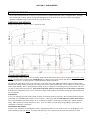


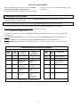


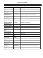
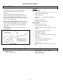


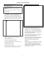

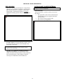


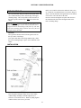


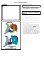


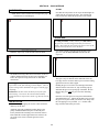
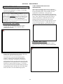
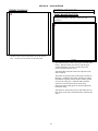
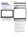


![[U2.11.01] Notice d`utilisation des raccords 1D-3D](http://vs1.manualzilla.com/store/data/006357368_1-711c857d113a1baf67f2f81df24cb590-150x150.png)