1
Ninja ZX-6R
Ninja ZX-10R
Kawasaki FI Calibration Tool
Instruction Manual
IMPORTANT
This manual provides how to change the fuel injection amount, sub-throttle opening, and
ignition timing of the racing ECU for the 2006/2007 Ninja ZX-10R, 2007/2008 Ninja ZX-6R,
2008/2009 Ninja ZX-10R and 2009 Ninja ZX-6R. This manual instructs the dealing method
briefly for the mechanic and being familiar with the personal computer (PC).
As for the basic knowledge, refer to the base Service Manual for the Ninja ZX-6R and
ZX-10R.
ZX1000D6F/D7F:
ZX600P7F/P8F:
ZX1000E8F/E9F:
ZX600R9F:
P/No. 99924-1365-02
P/No. 99924-1382-02
P/No. 99924-1388-02
P/No. 99924-1417-01
AFTER ANY MODIFICATION TO TUNE THE VEHICLE TO A COMPETITION MACHINE, IT
SHOULD NOT BE USED ON PUBLIC STREETS, ROADS OR HIGHWAYS. THE USE OF THIS
VEHICLE SHOULD BE LIMITED TO PARTICIPATION IN SANCTIONED COMPETITION
EVENTS UPON A CLOSED COURSE.
© 2008 Kawasaki Heavy Industries, Ltd.
First Edition (1): Nov. 25, 2008
1
User License Agreement
For Kawasaki FI Calibration Tool
This User License Agreement ("AGREEMENT") is a legal agreement between you (either an
individual or a single entity) and Kawasaki Heavy Industries, Ltd., a Japanese company,
("Kawasaki") for the Kawasaki FI Calibration Tool Software ("SOFTWARE"). By installing, copying,
or otherwise using the SOFTWARE, you shall agree to be bound by the terms of this AGREEMENT.
If you will not agree to the terms of this AGREEMENT, promptly uninstall the SOFTWARE and
destroy all the SOFTWARE, including its COPY if you have made one.
1. COPYRIGHT
All title and copyrights in and to the SOFTWARE (including but not limited to any images,
photographs, and text incorporated into the SOFTWARE) and the accompanying printed
materials are owned by Kawasaki and/or its licensor. The SOFTWARE is protected by copyright
laws and international treaty provisions.
2. GRANT OF LICENSE
(1) By purchasing the SOFTWARE, you are granted a license to use the SOFTWARE under
following conditions (2) and (3).
(2) USE: The SOFTWARE is licensed, not sold. You may install and use one copy of the
SOFTWARE on your computer.
(3) COPY: You may either (a) make one copy of the SOFTWARE solely for backup or archival
purposes or (b) install the SOFTWARE on a single computer provided you keep the original
solely for backup or archival purposes. All title and copyrights in and to the COPY are also
owned by Kawasaki and/or its licensor, and you may not use the COPY for any other
purpose than to recover the SOFTWARE on your computer.
3. LIMITATIONS
You may not modify, reverse engineer, decompile, or disassemble the SOFTWARE.
4. SOFTWARE TRANSFER
You may permanently transfer all of your rights under this AGREEMENT when the recipient
agrees to the terms of this AGREEMENT, provided you retain no copies, you transfer all of the
SOFTWARE and printed materials accompanied with it.
5. TERMINATION
Without prejudice to any other rights, Kawasaki may terminate this AGREEMENT if you fail to
comply with the terms and conditions of this AGREEMENT. In such event, you must uninstall
the SOFTWARE and destroy all of the SOFTWARE, including its COPY if you have made one.
2
6. LIMITED WARRANTY
(1) CUSTOMER REMEDIES: Kawasaki's and its suppliers’ entire liability and your exclusive
remedy shall be replacement of the SOFTWARE. This Limited Warranty is void if failure of
the SOFTWARE has resulted from accident, abuse or misapplication
(2) NO OTHER WARRANTIES: To the maximum extent permitted by applicable law, Kawasaki
and its suppliers disclaim all other warranties, either express or implied, including, but not
limited to, implied warranties of merchantability and fitness for a particular purpose, with
regard to the SOFTWARE. This limited warranty gives you specific legal rights. You may
have others, which vary from country, state or territory and jurisdiction to country, state or
territory and jurisdiction.
(3) NO LIABILITY FOR CONSEQUENTIAL DAMAGES INCLUDING PERSONAL INJURY AND
LOSS OF LIFE: To the maximum extent permitted by applicable law, in no event shall
Kawasaki or its suppliers be liable for any special, incidental, indirect, or consequential
damages including personal injury and loss of life whatsoever (including, without limitation,
damages for loss of business profits, business interruption, loss of business information, or
any other pecuniary loss) arising out of the use of or inability to use the SOFTWARE, even if
Kawasaki has been advised of the possibility of such damages. Because some countries,
states or territories and jurisdictions do not allow exclusion or limitation of liability for
consequential or incidental damages, the above limitation may not apply to you.
7. EXPORT LIMITATION
You shall agree not to export the SOFTWARE to foreign countries except for complying with
local laws and rules.
8. COMMERCIAL ARBITRATION
In case of trouble with the AGREEMENT, both parties assign Japan Commercial Arbitration
Association and under the rule thereof to settle a dispute and the award thereof shall be final
and binding upon both parties.
3
Contents
1. Kawasaki FI Calibration Tool Outline ························································· 6
1.1 System Function ········································································································· 6
1.2 Personal Computer (PC) Requirement ···························································· 7
1.3 System Configuration ······························································································ 8
2. Installation Procedure of Setting Program ·········································· 10
2.1 Installing Procedure ································································································ 10
2.2 File Structure··············································································································· 14
2.3 Uninstalling Procedure ·························································································· 15
3. Operating the Program ························································································ 17
3.1 Starting ··························································································································· 17
3.2 Each Map Edit Method ··························································································· 20
3.2.1 Map Edit ························································································································ 20
3.2.2 Map Axis Edit················································································································ 23
3.2.3 Multi Map Edit··············································································································· 24
3.2.4 Individual Value Edit ···································································································· 25
3.3 Changing ECU Data ································································································· 29
3.4 Other Functions········································································································· 33
3.4.1 Monitoring Function ···································································································· 33
3.4.2 Title Editor (Memo)······································································································· 35
3.4.3 Default Folder Setting Function·················································································· 35
3.5 File Saving ···················································································································· 36
3.6 Changing the Target Machine ············································································ 36
3.7 New Usable Functions ··························································································· 37
3.7.1 Plural Cells Data Selecting·························································································· 37
3.7.2 Plural Cells Data Copying ··························································································· 37
3.7.3 Plural Cells Data Changing Method ··········································································· 38
4. Menu List ························································································································· 39
4.1 Pull down Menu ········································································································· 39
4.1.1 File ································································································································· 39
4.1.2 Edit ································································································································ 39
4.1.3 Monitor ·························································································································· 39
4.1.4 Set·································································································································· 39
4.1.5 Window ························································································································· 40
4.1.6 Help ······························································································································· 40
4.2 Tool Bar (Icon) ············································································································ 40
5. Appendix·························································································································· 41
5.1 Connecting Method ································································································· 41
4
5.1.1 ’06/’07 ZX-10R··············································································································· 41
5.1.2 ’07/’08 ZX-6R················································································································· 43
5.1.3 ’08/’09 ZX-10R··············································································································· 45
5.1.4 ’09 ZX-6R······················································································································· 47
5.2 Caution Items when using the I/F Box··························································· 50
5.2.1 Caution when using the I/F Box·················································································· 50
5.2.2 System Requirements of I/F Box ················································································ 50
5.2.3 Caution when communicating between Setting Tool and ECU ······························· 50
5.3 Troubleshooting ········································································································ 51
5
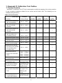
1. Kawasaki FI Calibration Tool Outline
1.1 System Function
Kawasaki FI Calibration Tool (FI Tool) is developed to modify the mapping of the racing machine
to gain operating conditions suitable for the course and the rider’s skill. The following are the
available setting functions.
Table 1 FI Tool Function
Model Name
Functions
1) Adjust the injected fuel
rate at acceleration
2) Adjust the injected fuel
rate of #1 and #4
cylinders
3) Adjust the injected fuel
rate of #2 and #3
cylinders
4) Adjust the injected fuel
rate of primary and
secondary injector*
5) Adjust the ignition timing
6) Adjust the sub-throttle
opening angle
7) Adjust the exhaust
device opening angle
8) Adjust the all injected
fuel rates of all cylinders
and operating area
simultaneously
9) Adjust the value of
engine over revolution
limiter
10) Set the fuel cut or not
at deceleration
11) Set the exhaust device
controlled or not
12) Set the Auto Shifter
Ignition Cut Length
13) Set the Pit Road RPM
Limit
14) Revolution
increase/decrease of
outside shift indicator
Available
Setting Range
’06/’07
ZX-10R
(ZXT00D)
‘07/’08
ZX-6R
(ZX600P)
‘08/‘09
ZX-10R
(ZXT00E)
‘09
ZX-6R
(ZX600R)
-30 % ~ +30 %
-30 % ~ +30 %
-30 % ~ +30 %
-10 % ~ +10 %
--
-20 % ~ +20 %
--
-15°CA~ +5°CA
-50 % ~ +50 %
-45 % ~ +45 %
---
--
--
--
--
-50 % ~ +50 %
---
--
--
----
--〇
--
----
-30 % ~ +30 %
0 ~ +300 rpm
-1000 ~ +700rpm
-1000 ~+1000rpm
-1000 ~+1200rpm
----
Use or Not Use
Controlled or
Full Open Fixed
Controlled or not,
set Ig. Cut Time
by gear range
Controlled or not,
set Upper Limit
RPM by gear
range
--
Controlled or not,
set the revolution
6
Model Name
Functions
15) Gear ratio of Kit
Transmission
16) Set the rev spike
controlled or not
17) Set the launch
controlled or not
Available
Setting Range
’06/’07
ZX-10R
(ZXT00D)
‘07/’08
ZX-6R
(ZX600P)
--
--
--
--
--
--
Use or not use,
set the gear ratio
Controlled or not,
set the sensitivity
or retard level
Controlled or not,
set RPM in
starting
‘08/‘09
ZX-10R
(ZXT00E)
‘09
ZX-6R
(ZX600R)
Note: mark shows the model has the function.
Note: * +: primary injector rate down and secondary injector rate up.
-: primary injector rate up and secondary injector rate down.
Note: CA shows rotating angle of crankshaft.
Note: On set the Auto Shifter (12) ’07/’08, ’09 ZX-6R has both cut time settings by ignition cut length
or fuel cut.
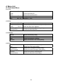
1.2 Personal Computer (PC) Requirement
The Kawasaki FI Calibration system operates on a Personal Computer (PC) having a serial
communication port with the racing electronic control unit (ECU) on the motorcycle through an
interface box (I/F Box).
Table 2 PC Requirement
Items
○
○
Recommendation
Operating System
Windows XP (US version, Japanese version)
CPU
Pentium 150 MHz or faster
Memory
64 MB or more
Hard Disk Drive
2 MB or more of free space
Display Resolution
1024 x 768 pixels or more, more than 256 colors
Port Connector
RS232C (D-sub 9 pin),
I/F Box cable can be connected to COM 1 ports
Other
Equipped with a mouse or a pointer equivalent to mouse
NOTE
Even if the recommended PC is used, the Kawasaki FI Calibration Tool program could not
operate correctly depending on the other applications installed to the PC.
If your PC does not equip 9-pin connector, use a suitable RS232C-USB adapter. Some adapter
cannot be communicated correctly depending on its specification.
7
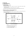
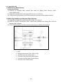
1.3 System Configuration
The Kawasaki FI Calibration tool kit consists of (1) Racing ECU, (2) Racing Main Harness or
Standard Harness plus Racing Sub-harness, (3) I/F Box, and (4) Setting Program. The Setting
Program must be installed to your PC.
(1) ECU
(4) Setting Program
installed to your PC
Connector for
Tool Kit (6P)
Serial Cable
(RS232C, 9P)
(3) I/F Box
(2)
Harness
Fig. 1 Setting Tool Connection
Table 3-1 Setting Tool for ZXT00D
Meter Type
ECU
I/F BOX
Optional Meter
Original Meter
Racing ECU P/No. 21175-0096
Racing I/F-BOX
P/No. 26031-0025 or 26031-0240 (Whichever is available.)
(1) Racing Main Harness
P/No. 26031-0426 or
(2) Racing Sub-harness
P/No. 26031-0427 plus
Std. Main Harness
Harness
Racing Main Harness
P/No. 26031-0425
Shift SW
Contact type of SW can be used.
Recommend the Shift Sensor made by Battle Factory or Dynojet.
Setting Program
CD or FD
8
Table 3-2 Setting Tool for ZX600P
Meter Type
Optional Meter
ECU
Original Meter
Racing ECU P/No. 21175-0145
I/F-BOX
Harness
Racing I/F-BOX
P/No. 26031-0025 or 26031-0240 (Whichever is available.)
(1) Racing Main Harness
P/No. 26031-0558 or
(2) Racing Sub-harness
P/No. 26031-0039 plus
Std. Main Harness
P/No. 26031-0561 (US Model)
Racing Main Harness
P/No. 26031-0559
Setting Program
CD or FD
Remarks: Racing sub-harness (P/No.: 26031-0039) doesn’t operate excluding the combination with
the above-mentioned standard main harness (P/No.: 26031-0561).
Table 3-3 Setting Tool for ZX600R
Generator Type
Optional Generator
ECU
Original Generator
Racing ECU P/No. 21175-0248
I/F-BOX
Harness
Racing I/F-BOX
P/No. 26031-0025 or 26031-0240 (Whichever is available.)
(1) Racing Main Harness
P/No. 26031-0789 or
(2) Racing Sub-harness
P/No. 26031-0327 plus
Std. Main Harness
P/No. 26031-0793 (US Model)
Racing Main Harness
P/No. 26031-0790
Setting Program
CD or FD
Remarks: Racing sub-harness (P/No.: 26031-0327) doesn’t operate excluding the combination with
the above-mentioned standard main harness (P/No.: 26031-0793).
Table 3-4 Setting Tool for ZXT00E
Meter Type
ECU
I/F BOX
Optional Meter
Original Meter
Racing ECU P/No. 21175-0212
Racing I/F-BOX
P/No. 26031-0025 or 26031-0240 (Whichever is available.)
(1) Racing Main Harness
P/No. 26031-0698 or
(2) Racing Sub-harness
P/No. 26031-0700 plus
Std. Main Harness
Harness
Racing Main Harness
P/No. 26031-0699
Shift SW
Contact type of SW can be used.
Recommend the Shift Sensor made by Battle Factory or Dynojet.
Setting Program
CD or FD
Remarks: The detail of connecting method is shown in section 5.1.
9
2. Installation Procedure of Setting Program
Program files will be supplied to users through Internet from “kawasakidirect”.
Download the Software “Kawasaki FI Calibration. EXE” to your PC and uncompress to suitable
folder
NOTE
○ Before installing the new Setting Program to the PC in which old version Program is installed,
save the old .est files as back-up and then un-install the previous Program.
2.1 Installing Procedure
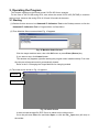
(1) Execute Setup.exe to start the Setup program.
(2) Then the screen shown in Fig. 2 appears.
Fig. 2 Setting Screen of Setup Program
Click Next to install the Program. Click Cancel to stop installing procedure.
(3) The Product License Agreement screen shown in Fig. 3 appears.
Fig. 3 Product License Agreement
Click Agree when you agree to the Product License Agreement. Click Not agree when
you do not agree to the Product License Agreement. Then the installing procedure is
stopped.
10
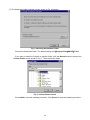
(4) Next the Serial Information screen shown in Fig. 4 appears.
Enter the information in both columns.
Fig. 4 User Information Registration / Authentication (Sample)
The Serial No is informed to you from the dealer.
The default settings of User Name and Serial No are vacant.
If you omit any of them, Next button is grayed out.
When the Serial No is wrong, an error message shown in Fig. 5 appears on the screen.
Input the correct Serial No in the column.
Fig. 5 Error Message
Click Next to install the Program. Click Cancel to stop the installing procedure.
11
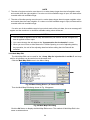
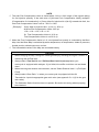
(5) The destination folder selection screen shown in Fig. 6.appears.
Fig. 6 Choosing Destination Folder
Choose the destination folder. The default setting is C:╲Program Files╲RACE╲FI-Tool.
If you want to install the Program to another folder, click the Browse button to display the
Choose Folder screen shown in Fig. 7. Then choose the folder.
Fig. 7 Choose Folder Screen
Click Install to start the installing procedure. Click Cancel to stop the installing procedure.
12
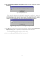
(6) After the Kawasaki FI Calibration Tool program is installed, the Setup finish screen shown in
Fig. 8 appears.
Fig. 8 Setup Finish Screen
If the destination folder has a file that has the same name of the file to be copied and
whose time stamp is newer than that for the file to be copied, the message screen shown in
Fig. 9 appears and the file cannot be copied. However, the installing procedure is normally
finished because the destination folder has the new data file with newer time stamp.
Fig. 9 Message Dialog when overwriting was not performed
(7) Click OK button to finish the setup. After the setup is finished, the shortcut icon for Kawasaki FI
Calibration Tool program is registered on both the Desktop and the Start Menu.
Click Cancel during the setup operation to quit the setup.
(8) Before starting Kawasaki FI Calibration Tool, restart your PC.
13
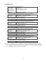
2.2 File Structure
Files to be copied into a destination folder
FI_Tool.exe
FI_Tool.bmp
FI_Tool FC.bmp
MCN_LIST.DAT
Setup.exe
Program file
256-color splash screen file
Full-color splash screen file
Uninstall file for execution
Files to be copied into the ZXT00E folder under the destination folder.
FI_Tool.ini
FI_Tool.stz
Setting file for FI_Tool.exe of ZXT00E
ZXT00E Configuration File
Files to be copied into the ZXT00E Work Folder
Standard_data.est
Data file for only ZXT00E
Files to be copied into the ZX600R folder under the destination folder.
FI_Tool.ini
FI_Tool.stz
Setting file for FI_Tool.exe of ZX600R
ZX600R Configuration File
Files to be copied into the ZX600R Work Folder
Standard_data.est
Data file for only ZX600R
Files to be copied into the ZX600P folder under the destination folder.
FI_Tool.ini
FI_Tool.stz
Setting file for FI_Tool.exe of ZX600P
ZX600P Configuration File
Files to be copied into the ZX600P Work Folder
Standard_data.est
Data file for only ZX600P
Files to be copied into the ZXT00D folder under the destination folder.
FI_Tool.ini
FI_Tool.stz
Setting file for FI_Tool.exe of ZXT00D
ZXT00D Configuration File
Files to be copied into the ZXT00D Work Folder
Standard_data.est
Data file for only ZXT00D
Note: When over-installing under the condition that the folders of ZX600K and ZX600M are existed
in the designated folders and in each folder the setting file is existed, those folders of ZX600K
and ZX600M are added in the machine select list.
14
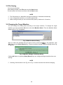
2.3 Uninstalling Procedure
Uninstalling operation can be executed on the Add/Remove service application in the Control
Panel.
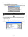
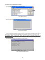
(1) Open the Control Panel screen from My Computer or Explorer screen.
Fig. 10 Control Panel Screen
Then click the Add/Remove icon.
(2) Add/Remove Programs Properties screen appears.
Fig. 11 Add/Remove Programs Properties screen
Click FI Calibration Tool and then click Add/Remove to start the Setup program.
15
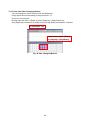
(3) The screen shown in Fig. 12 appears.
Fig. 12 Uninstall Starting Screen
Click Yes to start the uninstalling procedure.
(4) After the uninstallation is completed, Uninstall Completion screen shown in Fig. 13 appears.
Fig. 13 Uninstall Completion Screen
If you tried to delete the program but you couldn’t do it due to some reason (ex. the
program is starting), the message shown in Fig. 14 appears. In such case, delete the files
remaining in the screen folder by yourself.
Fig. 14 Message Dialog when some files were not deleted
(5) Click OK button to complete the uninstalling procedure.
In this step, setup.exe is left in the FI Calibration Tool folder, but it will be deleted when you start
the PC next time.
NOTE
○ When restarting after uninstallation is finished, the DOS window may remain open. (It occurs on
Windows 95, 98, Me.) At that time close the window by yourself.
16
3. Operating the Program
This chapter explains on the newest model ’09 ZX-10R for an example.
For the user of ’09 ZX-10R racing ECU, also select the model ’08 ZX-10R (ZXT00E) in machine
select screen, because the racing ECU of ’08 and ’09 models is the same.
3.1 Starting
(1) Double-click the shortcut icon Kawasaki FI Calibration Tool on the Desktop screen or click the
Kawasaki FI Calibration Tool in Program Menu on Start Menu.
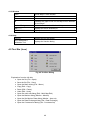
(2) Then Machine Select screen shown Fig. 15 appears.
Fig. 15 Machine Select Screen
Click the target machine name, then click OK button or press Enter (Return) key.
If you want to stop, click Cancel button.
This window only appears right after starting the program when installed initially. From next
time the pre-referenced model is automatically viewed.
Refer to the 3.6 Changing the Target Machine for changing models.
(3) The initial screen shown in Fig. 16 appears.
File menu
File-Open icon
Fig. 16 Initial Screen
It starts to load the data file (EST file) to be edited on the initial screen.
Go to the pull-down File menu and select Open, or click the File‐Open icon (left end) on
the toolbar.
17
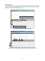
(4) The Open dialog shown in Fig. 17 appears.
Fig. 17 Open Dialog
Click the data file to be edited in the Open dialog screen. The selected data file name is
shown in the File name. Then click the Open button.
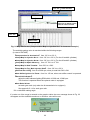
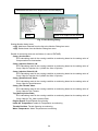
(5) The Menu dialog screen shown in Fig. 18 appears.
Labels
Fig. 18 Menu Dialog (in case of ZXT00E)
Select the mode to be edited in the Menu dialog.
The modes that can be used are as follows:
<Map Edit> Mode (in case of ZXT00E)
In this Mode you can edit the “Compensations” below.
Click one Label in the Menu dialog and click the OK button or Enter (Return) key, or double
click one Label, to display the Map Edit screen.
“Compensation for Acceleration”:
Regulates the rate of fuel injection at acceleration
“Comp. Map for Injection No.1”:
Regulate the rate of fuel injection at normal operation (For the #1 and #4 cylinders)
“Comp. Map for Injection No.2”:
Regulate the rate of fuel injection at normal operation (For the #2 and #3 cylinders)
“Comp. Map for Spark Advance”: Regulate the ignition timing
“Comp. Map for Sub Throttle”: Regulate the sub-throttle opening
“Comp. Map for Top_Main Injection Rate”:
Regulate the rate of primary and secondary fuel injection
18
“Pit Road Rev Limit ” : Regulate the pit road RPM limit.
“Auto Shifter Ignition Cut Time” : Regulate the ignition cut time at auto shifting
“Extra Shift Indicator” : Regulate the shift indicate RPM
“Gear Ratio Value”:Adjust the gear ratio when using the kit transmission.
<Setting Values Edit> Mode (in Case of ZXT00E)
In this Mode you can edit the eleven Values below.
Click the Constants list button to display the Setting Values Edit screen.
“OverRev shift Value”: Regulate the off-set value from the standard Over Rev Limiter.
“Select Fuel Cut [Use: 0 / Not Use: 1]”: Set the fuel-cut at deceleration.
“All Area Fuel Compensation Value”:
Regulate the rate of fuel injection for all operating ranges
“Select Auto Shifter [Use: 0 / Not Use: 1]”:
Set the auto shifter control.
“Select Pit Road Rev Limit [Use: 0/ Not Use: 1]”:
Set the pit road RPM limit control.
“Select Rev Spike Control” [Use: 0 / Not Use :1 ] ”: Set the rev spike control.
“Rev Spike Control Sensitivity [1 - 10 ] ”: Regulate the sensitivity of rev spike control.
“Rev Spike Control Retard Level [1 - 10 ] ”: Regulate the retard level of rev spike control.
“Select Gear Ratio” [Std: 0 / Kit Transmission: 1]”: Set the gear ratio.
“Select Launch Control” [Use: 0/ Not Use: 1 ] ”:Set the launch control.
“Launch Control Rev Limit shift Value”: Regulate RPM limit under the launch control.
<ECU Data Exchange> Mode
Click the Data Exchange button in the Menu dialog to display the Data Exchange screen.
Click this button when you want to load the data in the ECU or write the edited data in the
ECU.
<Multi Map Edit> Mode
Click the Multi Map Edit button in the Menu dialog to display the Multi Map Edit screen.
The Multi Map Edit can be used for the “Comp. Map for Injection No.1 and No.2” and map
edit for all cylinders can be carried out at the same time.
19
3.2 Each Map Edit Method
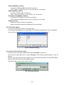
3.2.1 Map Edit
Select one Label in the Menu dialog and click the OK button or the Enter (Return) key, or
double click one Label to display the Map Edit Screen shown in Fig. 19.
Select one
Label
Fig. 19 Menu Dialog
In the Map Edit Screen, the Map to be edited will be displayed as the two-dimensional
graph (GRAPH) and the table (TABLE).
Tool bar
Map Z-axis switching button
Map switching button
Z-axis: throttle
opening angle (%)
Present target machine
Cursor Point
GRAPH
Area
1. Select point with mouse or arrow keys.
2. Move using mouse or arrow keys.
TABLE
Area
1. Select a cell by mouse or arrow keys mouse.
2. Input value or move the value by arrow key.
Fig. 20 Map Edit Screen (Compensation Map for Injection No.1 is shown as a sample.)
20
NOTE
○ If you closed the GRAPH or TABLE, open the Menu dialog on the Menu button of the Tool bar
and select the subject Map.
○ If you switched the subject Map using Map switching button, only the display switches. When
editing the subject Map, switch the Map by selecting the editing point of the Graph or Table area
of the subject Map.
Data Edit can be carried out either in the GRAPH or TABLE area and the editing method for
each area is as follows:
[Editing method on the GRAPH area]
Click a point on the graph to select the graph and the editing point of the engine rpm that is
the nearest position to the clicked point.
Drag & drop of the graph data: Press down the left button of the mouse to select the editing
point. After that, move the editing point up or down. Then, the data will be changed to the
possible setting value nearest to the release point.
(The direction of the engine rpm cannot be changed.)
Key allocation when a point on the line is selected
→ (or {Shift} + →): Switches the selected point to the right-side rpm
← (or {Shift} + ←): Switches the selected point to the left-side rpm
↑ (or {Page Up}): Increases the graph data by an LSB* at the selected point
↓ (or {Page Down}): Decreases the graph data by an LSB* at the selected point
{Shift} + ↑ (or {f・2}):
Switches the selected graph area (line number ) to another (Active row is moved down
in the TABLE)
{Shift} + ↓ (or {f・3}):
Switches the selected graph area (line number) to another(Active row is moved up in
the TABLE)
*LSB: Least Significant Bit
[Editing on the TABLE area]
Each value on the table can be directly edited by selecting the cell with mouse and putting
value by key strokes. The values in the data are always changed to the nearest values that
are possible to set. The values in the CPU are managed in hexadecimal data.
Key allocation when a cell in the table is selected
{Shift} + →: Switches the selected cell to the right-side rpm
{Shift} + ←: Switches the selected cell to the left-side rpm
{Shift} + ↑: Switches the selected cell to the upper-side cell
{Shift} + ↓: Switches the selected cell to the lower-side cell
{Page Up}: Increases the selected point by an LSB*
{Page Down}: Decreases the selected point by an LSB*
{Ctrl} + {Shift} + arrow: Switches the selected cells to the arrow direction
{Enter}: Defines data
*LSB: Least Significant Bit.
21
Line “6.3” is now selected.
Cursor Point
Line “6.3” data
The Line on which cursor
exist is shown in bold.
Line “6.3”
Cursor Point
Fig. 21 Map Edit Screen (Compensation Map for Injection No.1 is shown as a sample.)
The available setting value is restricted within the following ranges.
(In case of ZXT00E)
“Compensation for Accelertion”: from -30 % to +30 %
“Comp.Map for Injection No.1”: from -30 % to +30 % (For the #1 and #4 cylinders)
“Comp.Map for Injection No.2”: from -30 % to +30 % (For the #2 and #3 cylinders)
“Comp.Map for Spark Advance”: from -15˚CA* to +5˚CA*
“Comp.Map for Sub Throttle”: from -50% to +50%
“Comp.Map for Top_Main Injection Rate”: from -20 % to +20 %
“Pit Road Rev Limit”: from 0 to 5000 rpm, when pit road limit SW is ON.
“Auto Shifter Ignition Cut Time”: from 0 to 150 ms, when auto shifter control is operated.
“Extra Shift Indicator”:
adjust the shift indicator lighting RPM within 10,000 and 15,000 rpm.
This function is operated when the optional meter is equipped.
“Gear Ratio Value”:
set each gear ratio (only when the kit transmission is equipped.)
See appendix 5.1.4 for each gear ratio.
*CA: crankshaft rotating angle.
If a value out of the range is entered on the graph or table, the error message shown in Fig. 22
will appear and the available maximum or minimum value will be set.
Fig. 22 Error Message
22
3.2.2 Map Axis Edit
In the TABLE area the axis data (Engine Revolution and Throttle Opening) can be edited by
keying in the data directly after selecting the cell by mouse or keystrokes. The data is always
exchanged to the nearest available setting value.
Axis data of Engine Revolution
Axis data of Throttle Opening
Fig. 23 Map Axis Editing (Original Axis Data)
Fig. 24 Map Axis Editing (Sample Screen After Changing the Axis Data)
23
NOTE
○ The data of engine revolution must be set in a value always larger than the left neighbor value
and smaller than the right neighbor. If a value out of the available range is input, the data will be
rounded within the available range.
○ The data of throttle opening must be set in a value always larger than the upper neighbor value
and smaller than the lower neighbor. If a value out of the available range is input, the data will be
rounded within the available range.
If a value out of the available range is input to both ends of the axis data, the error message will
appear and the maximum or minimum available setting value will be set.
CAUTION
The axis data is applied to the all map simultaneously. Be caution that the changed axis
data is applied to other maps.
You cannot change the axis data at the “Compensation for Acceleration” screen.
When you move from an Axis Data cell of Throttle Opening to a cell of adjusting data by
key operation, the cell of the adjusting data line before editing the Axis Data will be
selected.
3.2.3 Multi Map Edit
The Multi Map Edit can be used for the “Comp. Map for Injection No.1 and No.2” and map
edit for all cylinders can be carried out at the same time.
Click the Multi Map Edit button in the Menu dialog
Fig. 25 Menu Dialog Screen ( in Case of ZXT00E)
Then the Multi Map Edit dialog shown in Fig. 26 appears.
Fig. 26 Multi Map Edit dialog
Click the OK button to display the Multi Map Edit screen. The method of Multi Map Edit is the
same as written above.
24
Quit the Multi Map Editing Mode
Click the Individual Edit button in the Multi Map Edit dialog to quit the Multi Map editing
mode and display the Map Edit screen set for the #1 Map.
Or, click a Map menu other than the Multi Map in the Menu dialog to display the Map Edit
screen for the selected Map.
Fig. 27 Multi Map Edit dialog
CAUTION
Never edit the Multi Map setting by selecting the axis data in the Table editing area, or the
axis data could be broken and the program could close.
NOTE
○ When selecting Multi Map editing mode, #2 Map data is overwritten with the #1 Map data.
○ When both the Map area and Data area are closed in the Multi Map editing, the Multi Map edit
mode is automatically quitted.
3.2.4 Individual Value Edit
In this Mode you can edit the values.
Click the Constants list button on the Menu Dialog to display the Setting Values Edit screen.
Fig. 28 Menu Dialog Screen
25
Then Fig. 29 appears.
Data entry and display screen
Move with shift key
+ arrow key
Fig. 29 Edit Constants List Screen (in case of ZXT00E)
<Setting Items: in case of ZXT00E>
The editable items in the Constants List are as follows:
All Area Fuel Compensation Value:
can be set in the range from –30 % to + 30 % (applied to all cylinders)
Over Rev shift Value:
set the off-set value from the standard Over Rev Limiter, can be set in the range from
–1,000 rpm to +1000 rpm
Select “Fuel Cut”: set the Yes or Not of Fuel Cut at decreasing the speed
Select “Auto Shifter”: set the Yes or Not of Auto Shifter control
Select “Pit Road Rev Limit”: set the Yes or Not of Pit Road RPM control
Select “Rev Spike Control”: set the Yes or Not of Rev Spike control
Rev Spike Control Sensitivity: set the sensitivity of Rev Spike control
Rev Spike Control Retard Level: set the retard level of Rev Spike control
Select “Gear Ratio”:
set the Yes or Not of Kit Transmission (Be sure to set when you use the Kit
Transmission.)
Select “Launch Control”: set the Yes or Not of Launch control
Launch Control Rev Limit Shift Value:
set the off-set value from the standard Launch Control Rev Limiter, can be set in the
range from –2,000 rpm to +3,000 rpm
Key allocation when a cell in the table is selected
{Shift} + ↑: Switches the selected cell to the upper-side cell
{Shift} + ↓: Switches the selected cell to the lower-side cell
{Page Up}: Increases the selected point by an LSB
{Page Down}: Decreases the selected point by an LSB
{Enter}: Defines the data
26
Input the value and press Enter.
Fig. 30 Edit Constants List (Setting Data Sample)
The setting values are shown in a table and each value can be directly edited by selecting the
cell with mouse and putting value with keystrokes. The values in the data are always changed to
the values nearest available setting values.
If a value out of the range is put in the table, the error message shown in Fig. 31 will appear
and the nearest available value will be set.
Fig. 31 Error Message
27
NOTE
○ The total Fuel Compensation Value is limited within -30% to +30% range of the original setting
for fuel injection quantity. If the total value of [All Area Fuel Compensation Value] multiplies
[Compensation for Acceleration] or [Comp. Map for Injection No.1(No.2)] exceeds the limit, the
total Fuel Compensation Value is set to –30% or +30%.
[Example]
Comp. Map for Injection No.1 (or No. 2): 20% up
All Area Fuel Compensation Value: 30% up
1.20 x 1.30 = 1.56, 1.56 > 1.30
So, Total Compensation Value is 30 % up
Total Compensation Value is not 56 % up
○ When the Fuel Compensation Value is 0 %, the injected fuel quantity is controlled by the Base
Map. And the Base Map is calculated by water temperature, air temperature, intake air pressure,
throttle position, altitude pressure, and etc.
○ The intermediate values of the Map are calculated linearly.
CAUTION
When changing the Map, change the values gradually by checking the engine condition or
measuring the Air/Fuel ratio.
Always select “Fuel Cut”=0 and “Pit Road Rev Limit”=1(not use) when your
motorcycle is equipped with catalyzer. If you failed, the muffler could burn out and break
down.
When removing the exhaust valve actuator, set the “Select Exhaust Valve” =1(Full Open
Fixed)
Always select “Gear Ratio” =1 when your motorcycle is equipped with the Kit
Transmission. Input the appropriate gear ratio value (see appendix 5.1.4 (3) for the gear
ratio value).
The Sidestand Switch function does not operate. Be caution at running when equipping
the sidestand.
28
3.3 Changing ECU Data
The data flow between ECU and PC is shown in Fig. 32.
PC
ECU
ROM
Memory
ROM Data Exchange
Read
Read/Verify
Operation
File Data
Memory
RAM
Write/Read/Verify
Edit Data
(Data on PC Screen)
RAM Data Exchange
Fig. 32 The Data Flow between ECU and PC
The racing ECU has two kinds of ECU data exchange methods.
(1) ROM data exchange:
All data can be exchanged collectively and it takes about one minutes depending on PC
performance.
For exchanging ROM data, even if the ignition switch turns off, the data will not be erased.
But the data cannot be exchanged when the engine is running. (Use ROM data exchange for
normal circuit riding.)
(2) RAM data exchange:
The data can be exchanged instantaneously with the limitation of exchanging items.
Exchanging data is possible while the engine running, however the data is erased when the
ignition switch turns off. (Use RAM data exchange for a temporary setting adjustment in
chassis-dynamo and the like.)
29
Operation method of ROM data exchange
Click the Data Exchange button in the Menu dialog
Fig. 33 Menu Dialog
Data Exchange screen is displayed as shown in Fig. 34.
Fig.34 Data Exchange
In case of ROM data exchange, the data on the PC screen cannot be written directly to ECU. It
is necessary to transfer the data temporarily to the operation memory in the PC (see Fig. 32).
The buttons “Read”, “Write” and “Verify” on the screen are operated mainly in the
operation memory. The operation content is displayed on the screen by pressing each button.
Then the Data Exchange screen shown in Fig. 35 appears.
Fig. 35 Data Exchange Screen
30
The use and operation for each button is as follows:
[Read]
Click this button to read the data into the PC memory. (In case of no data in PC memory, Read
is a must.)
You can read data from the following three data sources:
Read from
ECU Data: read the ECU data into the PC memory (when Monitor is in the Start
condition, the display is grayed out.)
Edit Data: read the editing data into the PC memory
File Data: read the (*.EST) data into the PC memory
[Write]
Click this button to write the read data of PC operation memory into the ECU or editing area.
There are two addresses to write.
Write to
ECU: write the data into ECU (when Monitor is in the Start condition, the display is
grayed out.)
Edit: write the data into the editing area as editing data
[Verify]
Click this button to select the data to be compared with the read data.
Compare with
ECU Data: compare with ECU data (when Monitor is in the Start condition, the display is
grayed out.)
Edit Data: compare with edit data
File Data : compare with data in a data file (*.est)
When the read data is same as the selected data, Same appears on the status indication area,
and when they are different, Not same appears.
[Clear]
Click this button to clear the data exchange area on the PC.
[Close]
Click this button to finish the data change (clear the operating memory) and close the Data
Exchange screen.
○
○
○
○
○
NOTE
In case of writing the editing data into the ECU, Read the editing data into the operation range.
Then Write the data in the operation range into the ECU.
After writing the data into the ECU, confirm the data to be written in is the same with the data in
the ECU by using the Verify function. The data may be written into the ECU incorrectly
according to the communication conditions.
The usable number of writing into the ECU is 65,500 times. If it exceeds the limited number,
error message of NOT Writing will appear. At that time replace with a new one.
Be caution, if you select Edit, the present editing data can be lost.
Write the data into ECU after confirming that the Ignition is turned on and the fuel pump and sub
throttle valve are stopping.
31
CAUTION
When operating the data into the ECU, wait until the fuel pump and the sub throttle valve
stops. Then execute next operation or turn off the ignition switch.
Operation method of RAM data exchange
The map and the edited content of each setting value in the RAM can be written to ECU unit
when the engine is running.
[Edited data exchange when the engine is running]
After the data edit, the selected data by Shift + Enter will be sent to the ECU unit.
NOTE
○ The data is sent to the ECU unit by 1 point (1 cell). If you select some cells, the data of the
selected cells are sent to the ECU unit.
○ The sent data is valid when the engine is running.
(The data is not memorized in the ECU unit.)
Be sure to save the edited data.
○ The map axis data cannot be changed. Change the map axis data in ROM.
32
3.4 Other Functions
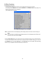
3.4.1 Monitoring Function
In this mode, the data inside the ECU can be displayed during engine operation.
Go to the pull down Monitor menu and select Monitor or click Monitor icon on the toolbar. The
Monitor dialog shown in Fig. 36 appears.
(This window can be resident)
Fig. 36 Monitor Dialog (in case of ZXT00E)
Start:Click this button to start displaying. When display starts, the button name will change to
Stop.
Stop:When this button is clicked during exchange process, the exchange process finishes and
this button name will change to Start.
Pressing Enter (Return) key can change the screen from Monitor dialog screen to Main Window.
To set the data inside the ECU, which can be monitored from the Monitor dialog, go to the pull
down Monitor menu and select Item set, or click Set Item icon on the toolbar. After the dialog
shown in Fig. 37 appears, select the item that you want to set.
33
Add/delete the items to be output on the monitor display
Items to be output on the monitor
Items
Fig. 37 Item Setting Dialog
Setting Monitor dialog items
>>[A]: Add items selected from the list to the Monitor Dialog Item area
<<[D]: Delete items from the Monitor Dialog Item area
Details of monitoring items are as follows (in case of ZXT00E):
Comp_Acceleration :
ECU calculating result in the running condition at monitoring based on the setting value of
Compensation for Acceleration
Comp_Injection Pulse #1, #4:
ECU calculating result in the running condition at monitoring based on the setting value of
Comp. Map for Injection No.1 (#1/#4: No.1/No.4 Cylinder)
Comp_Injection Pulse #2, #3:
ECU calculating result in the running condition at monitoring based on the setting value of
Comp. Map for Injection No.2 (#2/#3: No.2/No.3 Cylinder)
Comp_Spark Advance Value:
ECU calculating result in the running condition at monitoring based on the setting value of
Comp. Map for Spark Advance
Comp_Sub Throttle Value:
ECU calculating result in the running condition at monitoring based on the setting value of
Comp. Map for Sub Throttle
Top_Main Injection Ratio:
ECU calculating result in the running condition at monitoring based on the setting value of
Comp. Map for Top_Main Injection Ratio
Engine Speed: Engine Speed at monitoring
Intake Air Temperature: Intake Air Temperature at monitoring
Throttle Position: Throttle Opening at monitoring
Water Temperature: Water Temperature at monitoring
34
Pit Road SW[OFF:0/ON:1]:
Condition of Pit Road RPM Limit SW at monitoring
When “Select Pit Road Rev Limit” is set 0 (Used), you can monitor
Shifter SW[OFF:0/ON:1]:
Condition of Shifter SW at monitoring
When “Select Auto Shifter” is set 0 (Used), you can monitor
Rev Spike Cont.SW[OFF:0/ON:1]:
Condition of Rev Spike Control SW at monitoring
When “Select Rev Spike Control” is set 0 (Used), you can monitor
Diagnosis Code:
Diagnosis Code on sensors at monitoring
Refer to the Service Manual for Diagnosis Code information
3.4.2 Title Editor (Memo)
You can record the title (memo) for each edit data.
Go to the pull-down Set menu to select Title. The Title Editor dialog shown in Fig. 38 appears.
You can set the mode with the mouse and directly edit the data with keystroke.
Fig. 38 Title Editor Dialog
3.4.3 Default Folder Setting Function
In this mode, you can set the default folder when File Open is carried out.
Go to the pull down Set menu to select Directory. The Directory dialog shown in Fig. 39
appears.
Directly enter the folder name by keystroke or use the Browsing function in the folder search
dialog to select the folder from the existing folders.
Use the full path name to write in the File Path.
Fig. 39 Directory Dialog
35
3.5 File Saving
You can save the data.
After editing the Map, click File and next click Save button.
Put the name in the column and then click the Save button.
NOTE
○ The file extension is .est. When saving the extension is attached automatically.
○ If you change the extension, you cannot open the file.
○ When saving the data you can record the title (memo). Refer the 3.4.3 section.
3.6 Changing the Target Machine
You can change the editing data according to the target machine. To change the target
machine, go to the pull down Set menu and select Machine Select. Then the Machine Select
dialog shown in Fig. 40 appears.
Fig. 40 Machine Select Dialog
After you select the machine that you want to set by mouse operation or key operation, click
OK button or press Enter (Return) key. Then the machine change confirming dialog shown Fig.
41 appears.
Fig. 41 Machine Change Confirming dialog
Clicking OK button or pressing Enter (Return) key can change the target machine from next
starting.
NOTE
○ Selecting Cancel button in the Fig. 40 or Fig. 41 cannot execute the machine changing.
36
3.7 New Usable Functions
3.7.1 Plural Cells Data Selecting
You can select the plural cells. This is useful when copying the data to excel file or changing
the data simultaneously. (See Fig. 42).
Select the start point [Click (Left button)], and select the end point [{Shift} + Click (Left button)]
or [{Shift} + {Ctrl} + arrow key]
1. Click Left button
2. {Shift} + Click Left button
or {Shift} + {Ctrl} + arrow key
Fig. 42 Data Selecting Method
3.7.2 Plural Cells Data Copying
You can copy the selected data to Microsoft® Excel file by using Microsoft® Windows
clipboard.
Copy: {Ctrl} + {C} or [Pull down menu] → [Edit] → [Copy]
Paste: {Ctrl} + {V} or [Pull down menu] → [Edit] → [Paste]
FI Calibration Tool
Microsoft® Excel sheet
Copy: {Ctrl} + {C}
Paste: {Ctrl} + {V}
Fig. 43 Data Copying Method
37
:
3.7.3 Plural Cells Data Changing Method
You can change the value of plural cells simultaneously.
Firstly select the area according to the procedure 3.7.1.
A cursor is on end point.
Directly input the value + {Enter} or press {Page Up} / {Page Down} key.
One {Page Up} increases 0.78 points and one {Page Down} decreases 0.78 points.
FI Calibration Tool
Input value, ex.(5) + {Enter}.
or {PageUp} / {PageDown}
Fig. 44 Data Changing Method
38
4. Menu List
4.1 Pull down Menu
4.1.1 File
Open
Close
Save
Ctrl + O
Loads data file
Closes the loaded file
Names the file and saves it
Menu
F1
Displays the Menu dialog
Exit
Alt + F4
Finishes FI_Tool
Ctrl + Z
Cancels the data edit
4.1.2 Edit
Undo
Copy
Ctrl + C
Paste
Ctrl + V
Multi Map Edit
Individual Edit
Temporarily saves the data in cell(s) into clipboard
Paste the data in the clipboard
Displays the Multi Map Edit setting dialog
Finishes the Multi Map Edit
4.1.3 Monitor
Monitor
Displays the Monitor dialog
Start
Starts the Monitor Exchange
Stop
Finishes the Monitor Exchange
Item set
Displays the Monitor Item Setting Dialog
4.1.4 Set
RS232C
Title
Displays the RS232C setting dialog
Displays the Title setting dialog
Constants list
Data Exchange
Displays the Constants list setting dialog
Displays the Data Exchange setting dialog
Directory
Machine Select
Displays the Directory setting dialog
Displays the Machine Select dialog
39
4.1.5 Window
Open
Opens Map or Table window
Cascade
Cascades two or more windows
Title
Titles two or more windows
All
Switches the graph mode on the Map screen between
All and Single
Monitor Dialog
Moves the cursor to the Monitor dialog
MAP-*****
Displays the active windows list
TABLE-*****
Displays the active windows list
4.1.6 Help
Tool box
Displays the tool box dialog
About Kawasaki FI
Calibration Tool
Displays the Version dialog
4.2 Tool Bar (Icon)
Fig. 45 Tool Box Dialog
Explanation from the left side
Open the file (File - Open)
Save the file (File - Save)
Open the Menu dialog (File - Menu)
Copy (Edit - Copy)
Paste (Edit - Paste)
Undo (Edit - Undo)
Open the multi edit dialog (Edit - Multi Map Edit)
Open the Monitor dialog (Monitor - Monitor)
Open the Set Monitor Data dialog (Monitor - Item set)
Open the Data Exchange dialog (Set - Data Exchange)
Open the Constants list dialog (Set - Constants list)
40
5. Appendix
5.1 Connecting Method
5.1.1 ’06/’07 ZX-10R
(1) With Racing Main Harness
Connecting method
(1) Remove the Standard Main Harness and install the Racing Main Harness (P/No.
26031-0425, 0426).
(2) Replace the standard ECU with Racing ECU (P/No. 21175-0096).
(3) Connect the 6-pin connector of I/F Box to the 6-pin connector of Racing Main Harness.
(2) With Original Meter and Standard Main Harness
(1) Replace the original ECU with Racing ECU.
(2) Insert the Racing Sub-harness (P/No. 26031-0427) between the Racing ECU and the
Standard Main Harness.
(3) Connect the connector of I/F-Box to the connecting port of Racing Sub-harness.
Fig. 46 Connecting Method
1.
2.
3.
4.
5.
ECU
Racing Sub-harness (P/No. 26031-0427)
Connect to the auto shifter (blue).
Connect to the speed limit switch (black).
Connect to the I/F-Box (black).
41
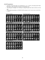
(3) Kit Transmission
Set Select “Gear Ratio” [Std: 0 / Kit Transmission :1 ] to “1” of the FI_Tool and input the“Gear
Ratio Value” of the map value as shown in the following chart.
If the 6th gear is changed except for A(STD), it is necessary to change the gear ratio value of
all the 1st to 5th gear.
Select A for 6th gear
1st
2nd
3rd
4th
5th
6th
A
3.13
(15/38)
2.54
(19/39)
2.15
(19/33)
1.89
(21/32)
1.71
(21/29)
1.62
(23/30)
B
2.95
(13/31)
2.41
(19/37)
2.22
(19/34)
1.92
(20/31)
1.80
(20/29)
C
3.00
(14/34)
2.61
(18/38)
2.17
(16/28)
1.95
(21/33)
1.73
(20/28)
Select B for 6th gear
D
E
2.86
3.22
(16/37) (15/39)
2.48
(18/36)
2.12
(21/36)
F
G
1st
2nd
3rd
4th
1.77
(21/30)
5th
6th
Select C for 6th gear
1st
2nd
3rd
4th
5th
A
3.36
(15/38)
2.72
(19/39)
2.30
(19/33)
2.02
(21/32)
1.83
(21/29)
B
3.16
(13/31)
2.58
(19/37)
2.37
(19/34)
2.06
(20/31)
1.92
(20/29)
6th
C
3.22
(14/34)
2.80
(18/38)
2.32
(16/28)
2.08
(21/33)
1.86
(20/28)
1.77
(21/28)
1st
2nd
3rd
4th
5th
B
2.95
(13/31)
2.41
(19/37)
2.22
(19/34)
1.92
(20/31)
1.80
(20/29)
C
3.00
(14/34)
2.61
(18/38)
2.17
(16/28)
1.95
(21/33)
1.73
(20/28)
B
3.05
(13/31)
2.49
(19/37)
2.29
(19/34)
1.99
(20/31)
1.86
(20/29)
1.77
(21/29)
C
3.11
(14/34)
2.70
(18/38)
2.24
(16/28)
2.01
(21/33)
1.79
(20/28)
F
G
1st
2nd
3rd
4th
1.90
(21/30)
5th
A
3.36
(15/38)
2.72
(19/39)
2.30
(19/33)
2.02
(21/32)
1.83
(21/29)
B
3.16
(13/31)
2.58
(19/37)
2.37
(19/34)
2.06
(20/31)
1.92
(20/29)
C
3.22
(14/34)
2.80
(18/38)
2.32
(16/28)
2.08
(21/33)
1.86
(20/28)
6th
F
G
1st
2nd
3rd
4th
1.77
(21/30)
5th
1.55
(24/30)
A
3.24
(15/38)
2.63
(19/39)
2.22
(19/33)
1.95
(21/32)
1.77
(21/29)
B
3.05
(13/31)
2.49
(19/37)
2.29
(19/34)
1.99
(20/31)
1.86
(20/29)
C
3.11
(14/34)
2.70
(18/38)
2.24
(16/28)
2.01
(21/33)
1.79
(20/28)
Select D for 6th gear
3rd
4th
5th
A
3.36
(15/38)
2.72
(19/39)
2.30
(19/33)
2.02
(21/32)
1.83
(21/29)
B
3.16
(13/31)
2.58
(19/37)
2.37
(19/34)
2.06
(20/31)
1.92
(20/29)
6th
C
3.22
(14/34)
2.80
(18/38)
2.32
(16/28)
2.08
(21/33)
1.86
(20/28)
D
E
3.07
3.45
(16/37) (15/39)
2.65
(18/36)
2.27
(21/36)
F
G
1.90
(21/30)
1.69
(22/28)
Therefore, the input gear ratio values are as shown below.
1st
2nd
3rd
4th
5th
6th
3.16
G
F
G
F
G
1.83
(21/30)
D
E
3.07
3.45
(16/37) (15/39)
2.65
(18/36)
2.27
(21/36)
1.90
(21/30)
1.69
(22/28)
2.72
2.27
2.08
1.83
42
D
E
2.96
3.33
(16/37) (15/39)
2.56
(18/36)
2.20
(19/33)
1.83
(21/30)
1.69
(22/29)
6th
Ex.:Select 1st to 6th gear as BADCAD combination.
Select each gear ratio from the chart “Select D for 6th gear”.
2nd
F
Select G for 6th gear
D
E
2.86
3.22
(16/37) (15/39)
2.48
(18/36)
2.12
(21/36)
6th
1st
D
E
2.96
3.33
(16/37) (15/39)
2.56
(18/36)
2.20
(21/36)
Select D for 6th gear
D
E
3.07
3.45
(16/37) (15/39)
2.65
(18/36)
2.27
(21/36)
Select F for 6th gear
A
3.13
(15/38)
2.54
(19/39)
2.15
(19/33)
1.89
(21/32)
1.71
(21/29)
A
3.24
(15/38)
2.63
(19/39)
2.22
(19/33)
1.95
(21/32)
1.77
(21/29)
1.69
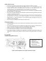
5.1.2 ’07/’08 ZX-6R
(1) With Racing Main Harness
1. Replace the ECU with
Racing ECU.
2. Replace the Main Harness
with Racing Main Harness.
3. Connect to the I/F Box
Fig.47 Connecting Method
(2) With Original Meter and Standard Main Harness
1.
2.
3.
4.
5.
6.
ECU
Standard Main Harness
Racing Sub-Harness
Connect to the I / F Box
Red lead of Sub-Harness
White / Green lead of
Sub –Harness
Connect Sub-harness to the diagnosis line of Main Harness
Fig.48 Connecting Method
A-A
Insert the White/Green lead
Insert the Red lead
Bad
Good
Bad
1.
2.
3.
4.
5.
Fig. 49 Inserting Method of Leads
Replace the ECU with Racing ECU.
Connect the Sub-harness connectors to the diagnosis line of Main Harness.
Insert the two leads of Sub-harness to the ECU connector as shown.
When you insert these lead lines, remove the orange colored cover.
Before attaching the cover, make sure that the lead lines are inserted.
43
(3) Kit Transmission
Set Select “Gear Ratio” [Std: 0 / Kit Transmission :1 ] to “1” of the FI_Tool and input the
gear ratio values which are selected from the following the chart.
Ex. Select 1st to 6th gear as AAAAAA combination.
Select each gear ratio from the chart.
1st
2nd
3rd
4th
5th
6th
A
2.714
(14/38)
2.200
(14/33)
1.850
(20/37)
1.600
(20/32)
1.421
(19/27)
1.300
(20/26)
B
2.643
(14/37)
2.167
(18/39)
C
2.571
(14/36)
2.125
(16/34)
1.650
(20/33)
1.500
(20/30)
1.391
(23/32)
1.458
(24/35)
1.346
(26/35)
Therefore, the input gear ratio values are as shown below.
1st
2.714
2nd
2.200
3rd
1.850
4th
1.600
5th
1.421
Input the gear ratio values to the Constants List.
(From Fig. 29 Constants List Screen )
44
6th
1.300
5.1.3 ’08/’09 ZX-10R
(1) With Racing Main Harness
Connecting method
(1) Remove the Standard Main Harness and install the Racing Main Harness (P/No.
26031-0698, 0699).
(2) Replace the standard ECU with Racing ECU (P/No. 21175-0212).
(3) Connect the 6-pin connector of I/F Box to the 6-pin connector of Racing Main Harness.
(2) With Original Meter and Standard Main Harness
(1) Replace the original ECU with Racing ECU (P/No. 21175-0212).
(2) Insert the Racing Sub-harness (P/No. 26031-0700) between the Racing ECU and the
Standard Main Harness.
(3) Connect the connector of I/F-Box to the connecting port of Racing Sub-harness.
Fig. 50 Connecting Method
1.
2.
3.
4.
5.
6.
ECU
Racing Sub-harness (P/No. 26031-0700)
Connect to the auto shifter (blue).
Connect to the speed limit switch (black).
Connect to the Rev Spike Control (black).
Connect to the I/F-Box (black).
45
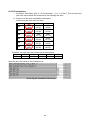
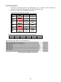
(3) Kit Transmission
Set Select “Gear Ratio” [Std: 0 / Kit Transmission :1 ] to “1” of the FI_Tool and input the“Gear
Ratio Value” of the map value as shown in the following chart.
If the 6th gear is changed, it is necessary to change the gear ratio value of all the 1st to 5th
gear.
The standard transmission of ’08/’09 ZX-10R consists of 1st:E、2nd:A、3rd:A、4th:B、5th:
C、6th:A.
Select A for 6th gear
1st
2nd
3rd
4th
5th
6th
A
3.13
(15/38)
2.54
(19/39)
2.15
(19/33)
1.89
(21/32)
1.71
(21/29)
1.62
(23/30)
B
2.95
(13/31)
2.41
(19/37)
2.22
(19/34)
1.92
(20/31)
1.80
(20/29)
C
3.00
(14/34)
2.61
(18/38)
2.17
(16/28)
1.95
(21/33)
1.73
(20/28)
Select B for 6th gear
D
E
2.86
3.22
(16/37) (15/39)
2.48
(18/36)
2.12
(21/36)
F
G
1st
2nd
3rd
4th
1.77
(21/30)
5th
6th
Select C for 6th gear
1st
2nd
3rd
4th
5th
A
3.36
(15/38)
2.72
(19/39)
2.30
(19/33)
2.02
(21/32)
1.83
(21/29)
B
3.16
(13/31)
2.58
(19/37)
2.37
(19/34)
2.06
(20/31)
1.92
(20/29)
6th
C
3.22
(14/34)
2.80
(18/38)
2.32
(16/28)
2.08
(21/33)
1.86
(20/28)
1.77
(21/28)
1st
2nd
3rd
4th
5th
B
3.40
(13/31)
2.78
(19/37)
2.56
(19/34)
2.21
(20/31)
2.07
(20/29)
C
3.47
(14/34)
3.01
(18/38)
2.50
(16/28)
2.24
(21/33)
2.00
(20/28)
F
G
1st
2nd
3rd
4th
1.90
(21/30)
5th
F
G
1st
2nd
3rd
4th
2.04
(21/30)
5th
6th
Select G for 6th gear
2nd
3rd
4th
5th
6th
B
3.05
(13/31)
2.49
(19/37)
2.29
(19/34)
1.99
(20/31)
1.86
(20/29)
C
3.11
(14/34)
2.70
(18/38)
2.24
(16/28)
2.01
(21/33)
1.79
(20/28)
D
E
2.96
3.33
(16/37) (15/39)
2.56
(18/36)
2.20
(21/36)
F
G
F
G
F
G
1.83
(21/30)
A
3.36
(15/38)
2.72
(19/39)
2.30
(19/33)
2.02
(21/32)
1.83
(21/29)
B
3.16
(13/31)
2.58
(19/37)
2.37
(19/34)
2.06
(20/31)
1.92
(20/29)
C
3.22
(14/34)
2.80
(18/38)
2.32
(16/28)
2.08
(21/33)
1.86
(20/28)
D
E
3.07
3.45
(16/37) (15/39)
2.65
(18/36)
2.27
(21/36)
1.90
(21/30)
1.69
(22/28)
Select F for 6th gear
D
E
3.30
3.71
(16/37) (15/39)
2.86
(18/36)
2.45
(21/36)
1.77
(21/26)
A
3.24
(15/38)
2.63
(19/39)
2.22
(19/33)
1.95
(21/32)
1.77
(21/29)
C
3.11
(14/34)
2.70
(18/38)
2.24
(16/28)
2.01
(21/33)
1.79
(20/28)
6th
6th
1st
B
3.05
(13/31)
2.49
(19/37)
2.29
(19/34)
1.99
(20/31)
1.86
(20/29)
1.77
(21/29)
Select D for 6th gear
D
E
3.07
3.45
(16/37) (15/39)
2.65
(18/36)
2.27
(21/36)
Select E for 6th gear
A
3.62
(15/38)
2.93
(19/39)
2.48
(19/33)
2.18
(21/32)
1.97
(21/29)
A
3.24
(15/38)
2.63
(19/39)
2.22
(19/33)
1.95
(21/32)
1.77
(21/29)
D
E
2.96
3.33
(16/37) (15/39)
2.56
(18/36)
2.20
(19/33)
F
G
1.83
(21/30)
1.69
(22/29)
46
A
3.13
(15/38)
2.54
(19/39)
2.15
(19/33)
1.89
(21/32)
1.71
(21/29)
B
2.95
(13/31)
2.41
(19/37)
2.22
(19/34)
1.92
(20/31)
1.80
(20/29)
C
3.00
(14/34)
2.61
(18/38)
2.17
(16/28)
1.95
(21/33)
1.73
(20/28)
D
E
2.86
3.22
(16/37) (15/39)
2.48
(18/36)
2.12
(21/36)
1.77
(21/30)
1.55
(24/30)
(4) Rev Spike Control
This control regulates the power when the engine revolution suddenly increases.
In case of using this control set “Select Rev Spike Control” in “0” on Constant List and also
connect SWITCH (P/No. 27010-0040) with the connector for Rev Spike Control in the
racing kit harness. (see “Racing Kit Manual” for the location of the connector).
When setting the knob stand in “B” this control functions. Cancellation is available by setting
the knob stand in “A” while running.
This control can adjust Sensitivity (the sensitivity in starting operation) and Retard Level (the
intensity in regulating the power).
Sensitivity has ten steps from 1 to 10 and is most easy to function at 10. Retard Level has
ten steps from 1 to 10 and is most intense to regulate at 10. At first, set Sensitivity and
Retard Level to 1, when this control is used. Gradually raise and adjust the step to be
suitable for your riding style.
This control is not available for preventing the vehicle-down.
(5) Launch Control
This control helps the rider make a stable start by keeping the engine revolution at the fixed
level in starting.
This control functions under the condition that “Select Launch Control” on Constant List is
set in “0” and when the engine revolution is over 8000 rpm while standing.
When this control is in operation the external shift indicator blinks.
This control ends when shifting up to 2nd or turning off the ignition.
The engine revolution in starting can be adjusted in the range of the fixed revolution and
-2000 rpm to +8000 rpm by changing ”Launch Control Rev Limit Shift Value” on Constant
List.
5.1.4 ’09 ZX-6R
(2) With Racing Main Harness
1.
2.
3.
Replace the ECU with
Racing ECU.
Replace the Main
Harness with Racing
Main Harness
Connect to the I/F Box
Fig.54 Connecting Method (The figure shows 2007 ZX-6R)
47
(2) With Original Meter and Standard Main Harness
1.
2.
3.
4.
5.
6.
ECU
Standard Main Harness
Racing Sub-Harness
Connect to the I / F Box
Red lead of Sub-Harness
White / Green lead of Sub
-Harness
Connect Sub-harness to the diagnosis line of Main Harness
Fig.55 Connecting Method
A-A
Insert the Red lead
Insert the White/Green lead
Fig. 56 Inserting Method of Leads
6. Replace the ECU with Racing ECU.
7. Connect the Sub-harness connectors to the diagnosis line of Main Harness.
8. Insert the two leads of Sub-harness to the ECU connector as shown.
9. When you insert these lead lines, remove the orange colored cover.
10. Before attaching the cover, make sure that the lead lines are inserted.
48
(3) Kit Transmission
Set Select “Gear Ratio” [Std: 0 / Kit Transmission :1 ] to “1” of the FI_Tool and input the
gear ratio values which are selected from the following the chart.
Ex. Select 1st to 6th gear as AAAAAA combination.
Select each gear ratio from the chart.
1st
2nd
3rd
4th
5th
6th
A
2.714
(14/38)
2.200
(14/33)
1.850
(20/37)
1.600
(20/32)
1.421
(19/27)
1.300
(20/26)
B
2.643
(14/37)
2.167
(18/39)
C
2.571
(14/36)
2.125
(16/34)
1.650
(20/33)
1.500
(20/30)
1.391
(23/32)
1.458
(24/35)
1.346
(26/35)
Therefore, the input gear ratio values are as shown below.
1st
2.714
2nd
2.200
3rd
1.850
4th
1.600
5th
1.421
Input the gear ratio values to the Constants List.
(From Fig. 29 Constants List Screen )
49
6th
1.300
5.2 Caution Items when using the I/F Box
5.2.1 Caution when using the I/F Box
1. When connecting/detaching the I/F Box to/from the connector of the motorcycle, keep the
ignition switch turned off.
2. Do not use the I/F Box except setting usage of the motorcycle ECU.
3. Never connect the I/F Box with connectors other than the specified connectors.
4. Never run the motorcycle with I/F Box and the PC connected to the ECU.
5. Install the connector for the terminal protection in the motorcycle connector, except when you
connect the setting tool.
6. Never use the I/F Box near the place where a strong magnetic field, such as near the
televisions and the radios, is generated and static electricity is generated.
7. Do not touch the terminal of the I/F Box connector directly, and do not keep the I/F Box in the
place where static electricity is generated.
5.2.2 System Requirements of I/F Box
1. Rated Voltage: 12 V
2. Operation Voltage: 8 ~16 V
3. Ambient Temperature: 5 ~ 35°C
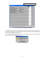
5.2.3 Caution when communicating between Setting Tool and ECU
Confirm the serial communication port of PC before using the setting tool.
It is necessary to match the communication port of the setting tool with the PC side.
1. Confirmation method of the communication port:
Open the Property of the System and check the serial port in the device manager. For Fig. 51,
correct serial port is COM1.
Communication
port (COM1)
Fig. 51 Device Manager of System Property
When “?” mark or “x” mark is displayed on the COM1, the communication between ECU and
PC cannot be done.
Cancel the “?” mark or “x” mark by referring the PC Instruction Manual or Help function of the
Windows.
50
2. Setting Method of the Setting Tool
Select the RS232C in the toolbar Set of the Setting Tool.
When the Dialog is opened, select the Port on the PC side and click the OK button. (If the
communication port is COM1, select the Port1.)
3. Connecting Method of I/F Box
Motorcycle
6Pin connector
Harness
D-sub
9Pin
To the serial
communications port
Personal computer
I/F Box
Fig. 52 Connecting Method of I/F Box
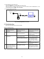
5.3 Troubleshooting
Refer the below table when you have troubles.
Table 4 Troubleshooting
NO.
Trouble
Cause
Countermeasure
1
Program cannot be
installed.
Operating method not
understood
Read manual carefully and
understand it.
2
Program does not work.
PC does not match with
required specifications.
Select suitable PC.
Available OS is Windows XP
(JP/US version)
3
PC cannot communicate
with ECU.
Incorrect connection of
communication cable.
Confirm connection (Refer
to the connecting method.)
Incorrect setting of serial port.
Confirm setting of serial
port. Change to correct
serial port again. (Refer to
5.2.3)
ECU is not powered ON.
Confirm ignition switch is
turned ON.
The Engine is running.
Perform Data Exchange
when engine is not running
but ignition switch is ON.
4
Cannot write data to ECU
or read data from ECU.
(Data Exchange function
does not work.)
51
Doc. No. 99929-0306-01