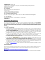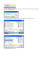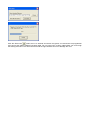
1
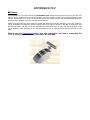
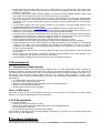
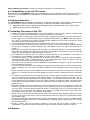
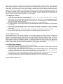
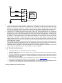
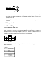
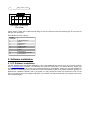
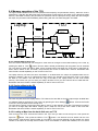
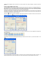
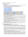
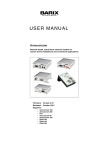
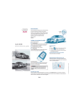
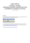
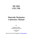
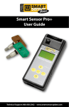
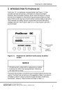
MANUAL Introduction
The manual is written in sequence for the beginner. If you are a first time user spend some time working
through it and understanding where and how the information are put together so that it will be easy to find
what you are looking for. If you are an expert, use this guide to jump to the right chapter. Is has a lot of
information and may be frustrating to find the answers if you don’t know where to look.
1. SPITRONICS TCU Introduction
This chapter discusses the SPITRONICS TCU as a product, how it is designed, and how it operates in
general.
2. Safety Precautions
This chapter discusses the all the safety precaution to the user and the product. Very important to read!!
3. Requirements
This chapter discusses the requirements for the TCU to operate the Transmission, and the PC specifications
to communicate with the TCU.
4. Hardware Installation
This chapter discusses the how to do the wiring and physical installation of the TCU. Be sure to read the
precautions during this faze!!
5. Software Installation
This chapter discusses the how to install the software and drivers to connect to the TCU.
6. Software Operation and Setup
This chapter discusses the operation of the tuning software and how to set the parameters up for each
specific Transmission.
7. Driver Operation of the Transmission
This chapter explains how to operate the transmission from the driver side.
8. Startup Procedure
This chapter discusses the basic sequence of actions to prevent damage during the startup faze.
9. Tuning Principles
This chapter discusses tuning information for the Transmission when it operates correctly. This is to enhance
performance and smoothness and correct operation of the TCU.
10. Fault Finding
This chapter discusses the symptoms and remedies of known faults.
11. Specifications
This is a list of specifications for the SPITRONICS TCU.
12. Firmware Programmer
This chapter discusses how to upgrade or change the SPITRONICS TCU Firmware.
SPITRONICS TCU
Welcome
Congratulations on your purchase of the SPITRONICS TCU Transmission Control Unit (TCU). We are sure
that you will be satisfied with this robust, compact and user friendly controller, which was designed to meet
today’s requirements. This TCU was developed around the people involved with Management Computers.
We hope that it will give you years of trouble free operation.
Please read this manual to learn about the safety precautions and design features of your TCU. Failure to
use and install this management system properly may cause injury to people or damage to equipment. This
Manual was written with the novice and professional Transmission tuner in mind, and we would like to urge
you to install the TCU according to our recommendations. This is the best way to get the most out of your
TCU.
Please read the Precautions before and after installation and before connecting the
TCU, to ensure that the correct procedures are followed.
1. SPITRONICS TCU Introduction
The SPITRONICS TCU is an aftermarket Automatic Transmission Control Unit which is designed to
customize shifting and control of many different transmissions. The requirement for this computer arises
mainly for the following reasons. Where existing computers failed and spares are scarce or none is existing.
When modifications to vehicles are done and existing TCU’s do not shift correctly. For racing and
recreational vehicles which must be customized. It is used as a cost effective replacement for existing TCU’s.
SPITRONICS TCU is a South African made product and can be customized for dedicated Transmissions and
models. It is a reliable compact system which is easy to mount in the driver’s compartment. No external
modules or converter boards are necessary.
The TCU is customized for specific applications and the installer does not have to pay for excess wires or
unused features. Nor does he have to buy separate modules and sensors which will increase the price.
Instead it is compiled with the correct harness and equipment as well as software and maps to ease
installation and setup. The software will also be calibrated for the sensors of the specific Transmission.
To make this TCU really versatile it comes with hardware electronics, firmware for the hardware which is
specific to each model of TCU and the powerful user friendly PC Tuning Software.
Hardware
The electronics is designed with inputs to read the sensors and then outputs to control the solenoids in the
transmission. It also has a user interface to select different Profiles and operating features. The main
operation required for the transmission is to control the shift solenoids which activate different gears and then
the pressure solenoids which smooth shifting and protect the clutches in the transmission. It also controls the
Torque Converter Clutch to reduce fuel consumption. In some cases there are features like 4x4 or diff lock
selection, reverse block out, smooth shifting solenoids and lockup clutch pressure control to name a few. The
hardware also consists of two type’s namely common positive and common negative solenoid wiring. This
means that some transmissions require 12 volt and other ground to control these solenoids.
Firmware
This part is not really the concern of the user but it is the operating system of the hardware electronics. It is
custom developed for each type of transmission and is essential for correct operation and shifting. This
firmware is tuned and set up from the PC software to operate the transmission as it is required by its
manufacturer. Once the tuning software is disconnected, this firmware will take over on its own and control
the transmission from there on.
Tuning Software
This software let the user customize the operation of transmission to work exactly as he prefers the shifting
process. The tuner can determines at which RPM’s and speed certain gear changes must take place. There
are also line pressures to control. Then the tuner can select up to four different Profile maps which can be
selected in the vehicle with a rotary switch. These maps can be set up for automatic, Tiptronic, towing, offroad driving and low range driving. It is totally up to the customer and his requirements for his vehicle.
The different models are as follows:
TCU Standard
This is the most basic and cost effective form of the TCU. It is made for common negative
transmissions and has 4 drivers. Signal required are revolution pulse, speed pulse, TPS signal and
inputs from the shifter, Profile switch and Tiptronic buttons. It has two LED’s to indicate basic modes
and operation. This is mostly for the basic transmissions like the Lexus A343E auto box.
TCU Intermediate
This TCU is the same as the standard model but has 6 or more drivers for more complicated
transmissions and comes in a common positive and common negative configuration. This is used for
the newer more intelligent automatic transmissions.
All wiring harnesses use screened cables for neatness of installation and to prevent interference from other
electronics or electromagnetic pulses, which may otherwise cause erratic behavior of the TCU.
1.1 Features
•
•
•
•
•
•
•
Up to 4 different Profiles for different setups can be loaded like Automatic, Tiptronic, Towing, Racing, Off
Road, and Low Range.
Internal Drivers up to 6 on existing models.
Harnesses and drawings included.
Adjustable gear settings for each gear.
Adjustable line pressure.
Speed and RPM signals used for shifting.
Small Compact South African Design.
1.2 Abbreviations
TCU – Transmission Control Unit
ECU – Engine Control Unit
PCM – Power Train Module
TCC – Torque Converter Clutch
EPC – Electronic Line Pressure
TFT – Transmission Fluid Temperature
TOT – Transmission Oil Temperature
SS1 – Shift Solenoid 1
TPS – Throttle Position Sensor
VSS – Vehicle Speed Sensor
TCS – Transmission Control Switch
MAF – Mass Air Flow
MAP – Manifold Air Pressure
ECT – Engine Coolant Temperature
2. Safety Precautions
The following guidelines will ensure proper operation the first time. Failure to install equipment correctly may
damage it or other equipment permanently. These failures will solely be the responsibility of the installer and
no guarantees will be given by us. Make sure you have read the Terms and Conditions on the website
www.spitronics.co.za before you install this TCU. By installing the TCU you automatically agree to these
conditions. All equipment is tested before it leaves the factory. We accept no liability for malfunctioning of the
equipment, or to injury that may result from installation or the use of the equipment. We also accept no
liability for costs of traveling of transportation of the equipment or parts or vehicle recovery due to failures of
any equipment. Please read the instructions and drawing and make sure you understand before you begin.
2.1 Operator Safety
Use only proper tools and products suited for auto installations. Sub standard products and installation
procedures may cause failure to the equipment having your customer break down in dangerous areas.
Use correct thickness of wire to carry the entire current requirement for that circuit. Too thin wires will
heat up and may start a fire causing injury.
Use fuses to protect each circuit separately. Joint circuits require large fuses which may heat and melt
lesser circuits causing fires.
Solder joints, and cover it with shrink sleeve to prevent loose connections which may cause fires.
Space solder-joints so that they do not sit next to each other minimizing the chance of a short circuit.
2.2 Equipment Safety
If you have a firmware programmer, do not load Ver. E1 EMU or Ver. E2 ECU firmware on the E20 or
E21 SPITRONICS TCU or visa-versa. It will damage the Micro because they are different. Make sure if
you have E21 hardware to use E21 firmware. Same with E20 electronics.
Never switch the power on, if the TCU enclosure is not grounded properly – this may damage the TCU
or sensors.
Test the installation with the test procedure before connecting the TCU – this will prevent damage due
to faulty wiring.
Install the free-wheel Diodes on relays to prevent spikes from interfering with the TCU.
Break out pins 1,4,6,7,8 & 9 on USB to RS232 converters and on serial cables. These pins are used for
other inputs and outputs of the TCU. It will hang the TCU and damage drivers. This does not apply to
Spitronics USB converters.
Do not connect screen wires on the Transmission. The starter will draw current through them melting
the harness.
The TPS must be connected correctly as it may damage the TCU or TPS permanently.
Ensure that wires are kept away from hot or sharp parts in the Transmission. Also ensure that
Transmission movement does not put strain on the wires, as metal fatigue will break the wires in time,
resulting in TCU failure.
Ensure a proper earth between battery negative and chassis and also between battery negative and
the engine. Do not earth the engine on the body or the body on the engine.
Do not disconnect the battery while engine is running. The alternator will create high voltage spikes
which may damage the TCU permanently. Ensure that all connections from the battery and alternator
are secure. Also connect the alternator charge wire directly to battery positive and not to the harness
somewhere.
The revolutions trigger input may not be connected to coil negative. The high voltage spikes on coil
negative will damage the unit permanently.
Make sure about the correct Jumper Settings on E21 hardware before you switch the ignition on.
Whenever it sounds as if clutches are slipping, back off the throttle immediately and increase the line
pressure. These clutches will damage in seconds and destroy the transmission.
Leave the 10 way connector disconnected when you switch the TCU on the first time until the setup is
completed. Then connect the 10 way connecter and switch on. Ensure that the fuse is the minimum
required value. Too large fuse will not blow resulting in driver or coil destruction.
Never engage the lockup clutch under load. It will damage the clutch it very quickly.
Ensure that the TPS and other signals operate correctly and are calibrated and set up properly.
Gearbox parameters are set by the manufacturer. With this software you will be able to change these
settings to your liking. Any wrong settings may damage the transmission and only you will be
responsible. So make sure that the settings are set according to the guidelines or consult an expert in
tuning to prevent damages.
Do not engage the lockup clutch in the lower gears as it will put unnecessary wear on the friction plates
of the clutch.
Do not connect 12 Volt directly to solenoids. Some are control solenoids which may damage in the
process. Make sure that the wiring is correct for this reason.
Solenoid supply voltage must be connected via a relay and fuse for protection.
3. Requirements
3.1 Transmission Requirements
The transmission must be of the electronically controlled type. The older transmissions were controlled by
hydraulic hardware inside the transmission and cannot be converted to computer control. Also note that the
mechanical shifter is still required for some of the transmission selections like Park, Neutral, Reverse and a
mechanical 1,2,3 and Drive setting. There may be a line pressure cable present on some of the
transmissions which must be correctly adjusted according to the manufacturer specifications. You will require
the following:
The transmission with electronic solenoids
The connectors on the transmission
Relevant control signals and sensors (RPM signal, TPS, Speed Sensor)
Shifter to select mechanical positions
Shifter position switches where specified
Notes on RPM Signal
This pulse must be a 12V to ground signal and may not be connected to coil negative. The high voltage
spikes on coil negative will damage the unit permanently.
3.2 PC Requirements
Pentium 4 Laptop
Windows XP with service pack 2 or later
Serial Port or USB device with USB to RS232 Converter (19200 baud rate)
Screen Resolution 1024*768
Ensure that the latest drivers for the PC are installed.
This software is developed under the latest Delphi environment. It requires a lot of processing speed and
may not run on older computers.
4. Hardware Installation
This chapter tells the user how to install and wire the SPITRONICS TCU. Be sure to read precautions
before attempting installation. There are a few do’s and don’ts’ to consider as well.
4.1 Compatibility to the old TCU series
Note that the Ver 3 SPITRONICS TCU may be upgraded to the Ver 20 software. The unit will have to be sent
to the factory for this upgrade at a cost and also an additional Profile switch with harness may be bought
separately.
4.2 Harness Selection
The SPITRONICS TCU has different harnesses for all different Transmission configurations. Make sure that
you have the right harness according to the drawing. These harnesses differ mainly as follows:
• Magnetic or Hall sensors require different voltages and are connected to the TCU on different pins.
• Different input and output combinations.
4.3 Installing Procedure of the TCU
Locate a convenient mounting position for the TCU inside the cab for water protection. Humidity and
heavy duty service units are available on request and will be custom made.
Ensure that the enclosure of the TCU is grounded with at least two metal screws onto the metal body of
the car. If the TCU is not bolted directly onto an earthed metal surface, you MUST make sure that you
run a 4mm2 ground wire to one of the TCU’s bolt holes, otherwise your TCU will not power up. There
may flow as much as 20A through the earth wire.
Connect the two black wires firmly to the enclosure base. This is the screens of all the cables.
Feed all wires of the harness, except the serial cable, through a hole in the firewall. A good seal around
the wiring is necessary to prevent damage and Transmission fumes and water from entering the
cockpit.
Each cable in the harness is marked to where it has to go. The same name is on the electrical drawing.
Wire colors are marked on the drawing for specific pin connections. Take special care for TPS wiring as
a fault here may damage the voltage regulator on the TCU.
Pull additional PVC sleeve over the cables for extra protection of the harnesses. This sleeve is
customized on your installation and dependant on routing of the cables.
The screened cables for the sensors must go to the sensor and connected as close as possible.
Connecting these wires to existing harness on the Transmission will cause the wires to pick up
electrical interference and cause erratic behavior of the TCU.
No screen wires may be connected or earthed to the transmission or engine. They are connected on
the TCU side to the enclosure.
Test each harness according to the drawing or to the optional test procedure to ensure correct wiring,
before connecting the TCU. This will indicate installation errors beforehand which may damage the
TCU.
Plug the harness into the TCU and taking care not to damage the pins and connectors. If it is sticky do
not force it in. Rather move the connector slightly from side to side till it mates with the TCU connector
pins.
The brown 12Volt supply wire for the solenoids on the common negative controllers must be wired via a
relay circuit directly from the battery with separate fuses in the positive supply for protection. Do not
wire any of these devices directly from the Ignition switch or on the same circuit as the TCU. This will
cause spikes which may damage or influence correct operation of equipment. Earth connections must
be as short as possible to earth and not connected to a common earth wire which is connected at a
distant ground.
Make sure that the correct wire thickness is used for each power electronic component. If wires are
common ensure that the wire is thick enough to carry the total current. Too thin wires will heat up and
may start a fire. The same goes for relays. Be careful of cheap relays. They can seize and start a fire.
Use 0.5mm2 of wire for every 5A of current. Also check pin numbers of the relays as they differ from
one manufacturer to the other. This mistake may be costly!
Solder each connection and use shrink sleeve rather than insulation tape. Stagger solder joins so that
they do not sit next to each other. Cover connections and loose wires with PVC or pigtail sleeve rather
than insulation tape.
Ensure that all electronic settings are correct before connecting the 10Way connecter. Certain settings
may damage equipment if not set to recommendations. Especially the coil output trigger level. Follow
the start-up procedure.
Ensure a proper ground from battery negative to the body and from battery negative to the
Transmission. This wire must be thick enough to carry the current of all the equipment in the car.
4.4 Sensors
There are three groups of sensors for speed and rpm sensing. Magnetic, Hall and Optic sensors. Hall and
optic sensors both give a square wave output and are treated exactly the same. They have electronic
components in the sensor which convert the signals to square wave. The Hall sensor uses magnetic field
where optic uses infrared light. In both cases a beam is broken and detected. Magnetic sensors are just a
magnetic coil around a magnet. The metal point passing this sensor induces a spike which has then to be
converted to a square wave so that the processor can work with it. These sensors have different inputs on
the TCU that is why the harnesses differ. They have different supply voltages which is selectable with
jumpers on the PC Board. See the drawing for correct settings.
4.4.1 Magnetic sensors
1. These sensors provide only a voltage spike to the TCU. The TCU will convert this spike to a usable
square wave to be used by the micro processor.
2. Each sensor has its own positive and negative wire from the TCU. Do not connect magnetic sensors
with common ground wires. The negative is connected to 5V and will damage the TCU if connected to
ground. Disconnect and isolate it first.
3. Make sure that the positives and negatives of the sensors are connected correctly.
4. In certain cases a 1 K ohm resistor may be connected between positive and negative to reduce spikes
in the signal.
5. Connect the screened cables from the TCU as close to the sensor as possible. Do not let single open
wires run along the spark plug wires or the coils as this will induce interference in the TCU causing
erratic firing.
6. Do not connect the screen to the Transmission. It is already connected to the body at the TCU.
7. Do not connect other devices to this pickup as it will interfere with the signal to the TCU.
Testing a Magnetic sensor
These sensors have a wired coil with a magnet. They normally have two wires. Some do have 3 wires which
have an earth which is not connected to the coil. The Coil resistance vary from 150 ohm to 1200 ohm
typically. If you swap the tester wires around you would measure the same resistance value. To test for
positive put the meter on milli volts DC. Connect the wires to the coil of the sensor. Move an iron object to the
sensor and look closely at the polarity indicator. If it indicate positive when moving closer to the sensor and
negative when moving away from the sensor, it means that the red wire of your meter is on the positive of the
sensor. If it is the other way round, then the black wire is on the positive of the sensor.
4.4.2 Hall & Optic sensors
1. These sensors already provide the TCU with a square wave.
2. Hall sensors work with magnetic fields but it does not mean it is a magnetic sensor. Failure to identify
this will cause incorrect wiring and no operation.
3. They have three wires. Each sensor has a positive (12V), earth and signal out pin. Connecting these
wrong may damage the TCU or the sensor permanently. If you are not sure which pin is which, ask
your agent to bench test it first with protection resistors to get correct pin-outs.
4. The TCU has an extra pull-up resistor of 2.2KOhm set with the jumper. If erratic misfires occur, another
1K Ohm resister may be connected between the signal and 12V wire on the sensor.
5. If the sensor requires a resistor in the positive wire to limit current, it must be put in separately.
Testing a Hall or Optic sensor
B a t+
1 K
M u lti M e te r
S ensor
1 K
+
•
•
•
•
•
-
These sensors normally have 3 wires. A supply wire, normally 12V, an earth wire and a signal out. This
sensor has electronic components that require power to operate. Connecting this sensor wrong my
damage it permanently. First test for resistance on all the pins and swap the test leads around to make
sure it is not a magnetic sensor. Put the meter on diode test and measure voltage drops over all the pins.
You should get V drops between 0.5V to 1.9V. This is your indicator that you have an electronic unit.
Now take 2 x 1K resistors and tie one end of each to the +12V. This will ensure that if you connect the
supply wrong you will not damage the component as the resistor will limit the current to 10mA. Now put
the ground on one pin and the 2 resisters on the other pins. Put the meter black wire on earth for the
remainder of the tests. Connect the meter red wire to any of the other pins. Now move an iron object to
the sensor or in the gap and away. If the signal varies between 0V and 12V then this pin may be the
signal output of the sensor. Now put the red wire on the other pin and repeat the iron process. This
voltage should not change. It may be less than 12V due to the drop over the resistor. If so then this is the
supply pin. With other words one of the resistor pins should respond rapidly to iron pulses while the other
one remains fairly constant.
Now change the earth pin to the next and repeat the process. Note that you may get a similar reaction if
you have the earth and the signal pins wrong. The indicator to see which one is which is to see which pin
reacts the most to the iron pulse. That pin is the signal output and the other one the earth.
Remember this is a guideline to black box testing and not a failsafe operation. Note point 4 above and
rather consult the specifications from the manufacturer or vehicle diagrams.
4.4.3 Throttle Position Sensor
•
•
•
•
•
•
This signal tells the TCU exactly what the driver is thinking.
The TPS must operate through the whole range of the throttle movement to ensure that the proper
operation of the TCU.
The TPS is normally connected to the Engine management. In this case only the signal wire needs to
be attached to the TPS signal. Do not connect the positive and negative onto the ECU wires. This will
damage the TCU or the ECU.
The TPS must be calibrated in the PC software as to operate correctly. This is done in the setup
menu before starting the Transmission. (see TPS calibration under Active Sensors)
The sensor is connected to 5V, ground and signal input. Connecting it wrong may damage the TCU
or TPS as you may short the 5V to ground. Test it before you connect it to the TCU.
Testing a TPS for the Correct Pin-Outs
Throttle Position Sensor
Black / Screen
Blue
Red +5V
Close
C
B
A
Open
•
1. Test the resistance with an Ohm Meter between 2 pins at a time. Each time move the throttle open
and close. If the resistance do not change and is approx 5000 Ohm, then you found pin A & C. The
remaining pin is B which is the wiper. Mark it as B.
2. Now test the B pin with one of the other pins. If it is below 500 Ohms then that pin is C. If it is above
4500 Ohm that pin is A.
3. Now to double check. Measure between B & C. if the throttle is closed the resistance is below 500
Ohm. If you open the throttle the resistance increases to above 4500 Ohm.
4. If you measure between A & C the resistance is around 5000Ohm and does not change with throttle
movement.
4.4.4 Oil Temperature Sensor
Reserved for Future development.
4.6 Additional Wiring
4.6.1 Pin References for the TCU
The TCU has two connectors for all wiring combinations. A 12 way connector for power and sensors, and a
10 way connector for all the outputs to the Transmission. Note that the TCU connects to ground via the
aluminum enclosure. It is not necessary that all the pins will be used. There may be additional wires on the
drawing that cannot be found on the pin descriptions. This is due to other connections in the harness to ease
with installation. The pin-outs are just for reference. Please follow the labels on the wiring harness when
connecting up your new TCU. All wires are grouped together for ease of installation.
7
8
9 10 11 12
1
2
3
4
5
6
Harness Connector
Pin View
Figure shows a view of the 12pin Female Plug on the TCU harness. Note the retaining clip on top and how
the pins are numbered.
E20 Hardware Lexus 4 Driver
12 way
connector
1
2
3
4
5
6
7
8
9
10
11
Down Shift Button
TPS sensor
Spare
Spare
Hall Sensor 2 Input
Hall Sensor 1 Input
Up Shift Button
Reverse Input
5 Volt Output
12V Ignition In
Mag. Sensor 2 Input
12
Mag. Sensor 1 Input
6
7
8
9
10
1
2
3
4
5
Harness Connector
Pin View
Figure shows a view of the 10pin Female Plug on the TCU harness. Note the retaining clip on top and how
the pins are numbered.
E20 Hardware Lexus 4 Driver
10 way
connector
1
2
3
4
5
6
7
8
9
10
Line Pressure Sol
Spare
Shift Sol No 1
GP Out 1
Tiptronic LED+
Lockup Sol
Spare
Shift Sol No 2
+12 Volt In for Solenoids
Lockup LED+
5. Software Installation
5.1 PC Software installation
The PC Software does not require installation. It is an executable file and can run from any memory medium.
See PC Requirements however. The software will create an ecu.ini file in the same directory where your
software is run from. This is to save your preferred settings in the software. When you start the software for
the first time, it will prompt you to accept the Terms & Conditions as laid out by Spitronics Micro Ignitions cc.
Read these conditions carefully and if you agree you may except the terms and continue to work on the
ECU. If you press cancel the program will close. If you load a new manual it will ask you to agree to the terms
and conditions again.
There is also an html help file. When you click on manual button,
this file and then you can access the manual from the PC software.
guide the software to
5.2 Spitronics USB driver installation
Go to the Spitronics USB Driver file on the CD. Activate the USB Setup.exe file. The software will install
automatically. It may take a couple of minutes on slower laptops. Now insert the USB cable into the PC.
Windows will detect the cable and install the driver for it. If it does not connect to the TCU see Changing the
Com Port Settings below.
5.3 RS232 Computer to TCU interface
The TCU communicates to the computer via the serial RS232 interface. It operates at 19200 baud rate. See
the drawing for connection diagrams.
Communication can also be achieved by USB via a USB to RS232 converter cable. Ensure that the drivers
for the cable are installed according to manufacturer specifications. When using other than Spitronics cables,
you have to break out pin 1,4,6,7,8 & 9 as they are used for other inputs and outputs such as for
programming the TCU as well as the launch control buttons. See drawing. On a serial connector provision is
made for hardware handshaking on printers etc. It is not used for these management electronics. The
Spitronics USB converter you do not have to break out the pins as they are internally disconnected.
DB9P Extension Cable
DB9P Male - Pin View
1
X
X
X X X9
6X
2
2
3
3
5
5
Earth
5
Note: These cables are optional and can be bought from the agent, computer shop or made in some cases.
6. Software Operation and Setup
6.1 Button Description
6.2 Connecting a PC to the TCU
6.3 Changing the USB Comport in Windows Device Manager
6.4 Memory operation of the TCU
6.5 Selecting Different Pages in the Software
This chapter will explain how the software operates and how to set it up for your specific Transmission. The
TCU comes preconfigured so that you don’t have to go through the tedious process of configuring all the
different parameters, to get the Transmission to start. There are however certain checks on different
Transmissions to get the TCU to work properly. Failure to do this may damage the TCU or components of the
Transmission which will solely be your responsibility. Refer to the drawings of your model to see if your
Transmission has a special setup procedure.
6.1 Button Description
Open a saved MAP from the hard disk into the PC Software.
Save MAP data from the PC or TCU on the hard disk.
Print MAPS to a printer.
Read the data MAP from the TCU into the PC Software.
Write to TCU – Write de TCU data into the Flash memory to make the changes permanent.
Lock the Data Maps and change the Customer Code.
Enable or disable the mouse pad for adjustments on the tuning graphs.
Information on the Agent and the TCU.
Quit the Program.
Do adjustment only where the real-timer bars are on the different graphs.
TCU is Online and can be adjusted.
TCU is offline.
6.2 Connecting a PC to the TCU
Connect the optional serial cable or RS232 converter cable to your laptop or PC and to the TCU. (Remember
to break out pins 1,4,6,7,8 & 9 if it is not a Spitronics USB converter)
Switch the ignition on and check if the yellow LED is on. Open the TCU PC software. If the TCU is connected
the PC software will pick it up on the Com port automatically and connect to it. If it did not, check your
connections again. Note that if you use the USB converter cable, that the com port must be Com 10 or lower.
You can correct this in the Device Manager of Windows XP. You are now ready to begin with the tuning on
your TCU.
6.3 Changing the USB Comport in Windows Device Manager
One some laptops, Windows will install the USB on a Com Port higher than 10. This is a Windows driver
problem and then the Com Port is not detected automatically. You need to change it to lower than 11. Follow
these steps:
1. Left click on Start (left bottom)
2. Right Click on My Computer (or in desktop My Computer)
3. Click on Properties
4. Click on Hardware
5. Click on Device Manager
6. Click on Ports (Com & LPT)
7. Right Click on Prolific USB to Serial Com Port (Com 11or higher)
8. Click on Properties
9. Click on Port Settings
10. Click on Advance
11. Select a Com Port lower than 11 (if all is in use choose 5 to 10 and press OK)
12. Click on OK and close
6.4 Memory operation of the TCU
The figure below indicates how the TCU operates with temporary and permanent memory. When the TCU is
powered up, it will take the data maps from the permanent FLASH memory and save it in the temporary RAM
memory. This RAM is used by the processor for operation and the Laptop for tuning. When the user changes
the maps, the processor will immediately start working with the new data changed in the RAM.
Laptop
TCU
RS232
Write to TCU
button
RAM
Tempory
Working
Memory
Load
Changes
Read from
TCU
RAM
Tempory
Working
Memory
FLASH
Permanent
Storage
Memory
Save
Hard Disk
Permanent
Storage
Memory
Power On
Processor
Maps in Use
Outputs & Inputs
6.4.1 Saving data in the TCU
Once the user is satisfied with his changes he must save his changes in the FLASH memory in the TCU, by
pressing the Write to TCU
button. Now the data is stored permanently and the ignition can be switched
off. If he does not save this data in flash, all his changes will be lost when the TCU power is switched off.
When data is written to the TCU flash, the processor will cut-out for about half a second. Remember that
each Profile is saved separately on the PC and in the TCU.
The laptop memory will have the same information in its RAM when the maps are uploaded after the PC
software is started. If the car is switched off without saving, the operator may switch the TCU on and press
the Write to TCU button. This will save the copy of the data in the Laptop RAM, into the TCU FLASH
memory. This is also how you can save your map in another TCU if you don’t want to save to hard disk first.
Remember that each Profile is saved separately on the PC and in the TCU.
6.4.2 Saving a Map to the PC
The user may also save the Laptop RAM or TCU data to the hard disk so that the maps maybe recalled later
or if different settings are desired. This is done by pressing the Save Settings
button. Choose the Profile
in the TCU that you want to save a map from.
The user has the option of saving the Ram data on the PC or the real-time TCU data. This feature is useful if
you want to change Map data offline. Simply open a Map file, edit it and save it back to the hard disk.
Remember that each Profile is saved separately on the PC and in the TCU.
6.4.3 Loading a Map from the hard disk onto an TCU
First connect to the TCU. Choose the Profile in the TCU that you want to load a map into. Then press the
Open file
button. Then press the Write to TCU
button. The data will now be written into the TCU
flash memory. Note that the serial number is not written in the process although for this session the serial
number is the same as the Map serial number. Once the software is closed and restarted, the TCU serial
number will be displayed. Also note that if an incorrect version of the map is loaded, a check box will warn
you of it.
6.4.4 Locking a MAP on the TCU
The tuning MAP on the TCU can be locked to prevent other users from copying it or changing settings on it.
This feature is to let Transmission builders install protection settings on the TCU for guarantee purposes.
Note however that you can overwrite the code by loading another MAP onto the TCU. This would however
indicate to the agent that tampering took place and may void guarantees.
The Agent has the option of changing the customer code for his reference. He can protect it with a password
and leave the maps open. It would mean however that the customer cannot lock his own maps under the
code as they use the same code for protection.
Press the
button and enter a password. Select which protection is required. Press Lock, Exit and then
press the Write to TCU
button to save it to the Flash memory.
To change the Customer code you need to put in the Agent Password which is only supplied to the agents by
the manufacturer.
To unlock the TCU enter the same password that you used to lock the Code. If you press the Write to TCU
button, the maps will stay open.
If you changed data and quit the program or switch the TCU off without saving the data in the flash, the
software will prompt you to take action with one of the following blocks so that the data will not be lost.
6.5 Selecting Different Pages in the Software
6.6 Start (F1)
6.7 Setup (F2)
6.8 Maps (F3)
6.9 Logger (F4)
6.10 Manual (F5)
Press on any of these buttons to activate the different pages in the
software. By pressing the alt button you will see the hot keys for these buttons.
The function keys are easier to press during driving.
6.6 Start (F1)
This is where the program will start the first time. On this page all the action events is logged for information.
It will also display the TCU information of the current TCU. Take note of the Warning as it is important and
binding by Law. See the Terms & Conditions on our website.
6.6.1 Version Numbers
The designer reserve the right to do changes to existing designs and harnesses as he keeps on developing
software and hardware. The market change all the time as new ideas submerges. The TCU has a version
number system so that the user knows which drawing and also which tuning MAP goes with which TCU
firmware. There is also a document which explains about the hardware and software changes made between
different versions.
TCU Version will indicate the product namely SPITRONICS and which model is connected. Model is
Standard, Intermediate or Advance.
Firmware Release is the hardware, firmware and software release information. This is very important as it
must coincide with the PC software. It is also written with a permanent marker on the enclosure but this my
rub off during installation.
2.2.1.A In the sample means: PC Software Ver. 2, Hardware number 2 (SPITRONICS), Protocol Ver.1,
Firmware Ver. A.
The PC software also has a version number in the name part of the file or
on the Top information bar. Keep older versions for old TCU versions. TCU firmware can be upgraded by an
agent to accommodate changes in the latest PC software. Version 2.20.1.0 TCU must be programmed with
Ver. 2.20.1.0 PC software. The alphabetic number if any will indicate later version changes in the TCU or PC
but does not change the protocol of Ver.2.20.1 software. This may differ from software to TCU but does not
matter.
Program is a number given to each TCU firmware program to identify them apart. Behind the number is a
short explanation of the type of program. On some programs there is a last letter indicating a B for Buttons or
P for Profile Switch. See file on CD for a list of these program numbers available.
Serial Number is keep track of each TCU sold. It is also engraved on the enclosure of the TCU. The number
for ex PP-PP-999999-15 means as follows:
PP – Agent which this unit was distributed to
PP – Customer which this unit was sold to – this can be changed by the Agent for his own reference.
999999 – serial number
15 – model function no
TCU model function numbers are as follows:
3
Standard TCU
11
15
Intermediate TCU
Advance TCU
6.7 Setup (F2)
6.7.1 Transmission Setup (Alt 1)
6.7.2 Timing Setup (Alt 2)
6.7.3 Fuel Setup (Alt 3)
6.7.4 Sensor Setup (Alt 4)
6.7.5 Turbo Setup (Alt 4)
6.7.6 Real-Time Data and Bars
Click on the setup tab to get information on the configuration of your Transmission. Most parameters are
being preset before the TCU has been shipped. Ensure that these settings are correct as some may damage
components on your Transmission or the TCU itself.
Click on of these icons to adjust different settings in the setup page. Activate the Hot-Key by pressing the Alt
button plus the correlating number as in the icon block.
6.7.1 Transmission Setup (Alt 1)
6.7.1.1 Map Information
The Map Information screen contains customer and vehicle information for a specific transmission. It saves in
the TCU and PC. This is used to identify different tuning maps from each other and it does not affect any
tuning on the Transmission.
6.7.1.2 Transmission Configuration
Number of Gears – This setting tells the software how many forward gears the transmission has. In some
firmware Maps this setting is forced and cannot be changed.
Torque Converter Stall Speed – This setting is used in some firmware programs to control the lockup
minimum engage RPM’s.
Number of Shift Solenoids – This setting tells the software how shift solenoids the transmission has. In
some firmware Maps this setting is forced and cannot be changed.
6.7.1.2 Vehicle Information
Cylinders – Number of cylinders on the engine can be typed in this block. It is not used by the current
firmware but reserved for future development of different firmware.
Engine Idle RPM – Idle RPM of the engine can be typed in this block. It is not used by the current firmware
but reserved for future development of different firmware.
Engine Max RPM – Maximum RPM of the engine can be typed in this block. It is used scale the gear map
graphs so that the whole graph can be used for tuning.
RPM Pulses / Revolution – This setting is the number of pulses that the RPM signal sends to the TCU. It is
used for correct revolution calculation and display.
Maximum Speed – This setting is used to adjust the speedometer maximum speed display.
Speed Sensor Pulses / Rev – This setting is the number of pulses that the Speed signal sends to the TCU.
It is used for correct speedometer calculation in conjunction with the Speedometer Calibration value.
TCC Off TPS High – When the throttle is pressed more than this setting in %, the lockup will be switched off.
This will protect the TCC with hi torque engines.
TCC Off TPS Low – When the throttle is released more than this setting in %, the lockup will be switched off.
This will smooth the down shifting of the Transmission.
The last two features can be made 0% and 100% to deactivate if you require the lockup to stay on.
6.7.1.3 General Purpose Outputs
General Purpose Outputs – It is not featured by the current firmware but reserved for future development of
different firmware and hardware.
6.7.2 Sensor Setup (Alt 2)
6.7.2.1 Active Sensors
RPM Input Sensor – This sensor cannot be disabled as it is required by the current firmware.
TPS Input Sensor – This throttle position sensor tells the TCU what the driver is thinking. It is very important
that this sensor operate, and is calibrated, correctly. It cannot be disabled as it is required by the current
firmware.
To calibrate the TPS, click on the Calibrate button. Click the Reset button. Press the fuel pedal in completely
and press F1. Release the pedal completely and press F1 again. Click the OK button. Then click on the Write
to TCU
button. When you switch the TCU off and on again, the TPS bar should indicate 0% when pedal
is released and 100% when pedal is pressed.
Speed Sensor – This speed sensor tells the TCU how fast the road speed is. The road speed is used on
each MAP to help with the decision of when to shift gears to ease driving. It is very important that this sensor
operate, and is calibrated, correctly. It cannot be disabled as it is required by the current firmware. First set
the RPM Pulses / Revolution on the setup page to the correct setting. Then use this value with a GPS or
the car speedometer to read the correct speed. If you increase the value the speed will be higher and also
the other way round.
Oil Temp – This sensor is disabled and reserved for future development.
Map Sensor – This sensor is disabled and reserved for future development.
Reverse Logic – This sensor is important for the TCU as is not allowed to shift gears while in reverse. The
arrow on the right when indicating blue and down, tells the TCU that the reverse signal give a ground or earth
pulse when reverse is selected. When the arrow indicate Red and up, it tells the TCU that the reverse signal
give a 12 volt pulse when reverse is selected. It cannot be disabled as it is required by the current firmware.
6.7.2.2 RPM / Speed Sensor Calculation
RPM / Speed Sensor Calculation – This sensor cannot be changed as for the current firmware. It is
reserved for future development.
6.7.2.3 Profile Options
These options allow the user to set up different Map operations for the TCU.
Drive / Overdrive – This setting will allow the TCU to select overdrive or not, during automatic mode. It is
handy if the vehicle is normally used for towing or in mountains.
Tiptronic On / Tiptronic Off – This setting will allow the driver to change gears with the buttons in the
specific Profile.
LED Function Mode / LED Gear Mode – This setting alternates between 2 different LED display modes.
In Function Mode it the Green LED displays Off for Overdrive, On for Drive and Flashing for Tiptronic
while the Red LED is On when the Lockup clutch is engaged. In Gear Mode the Red LED indicates if Shift
Solenoid no 1 is engaged and the Green LED indicates if Shift Solenoid no 2 is engaged. This is handy to
see if and when the TCU shift between different gears.
6.7.3 Solenoid Setup (Alt 2)
These options are used to set up different Shift Solenoid configurations for each shifter position, as well as
the different gears in the shifter positions, if they are allowed. Most firmware is preprogrammed and will not
allow the user to change any of these settings.
6.7.4 Maps (Alt 1)
6.7.5 Gear Maps (Alt 1)
These Maps are used to set up gear to shift on its own pattern and according to certain criteria. It is important
not to set weird patterns outside the ability of the automatic transmission. See the precautions for the tune-up
settings to prevent damage to the TCU.
The dark blue dot is called the Marker and is a representation of TPS position versus engine RPM. This
Marker will move freely over the page, up and down, left and right.
The red line is the Down Shift Line and has three dots called High Dot, Middle Dot and Low Dot. When the
marker moves to the left of the Down Shift Line, the lower gear will be selected.
The blue line is the UP Shift Line and has three dots called High Dot, Middle Dot and Low Dot. When the
marker moves to the right of the UP Shift Line, the higher gear will be selected.
The green line is the Lockup Line and has two dots called High Dot and Low Dot. When the marker moves to
the right of the Lockup Line, and the Marker is below the High Dot TPS % position, the Lockup clutch will be
engaged.
To change the position of these Dots, click on the Dot, it will become Red, and move it with the cursors to the
required positions.
If Real Time
is active, these maps will change as shifts in the transmission takes place.
This Gear bar indicates which Gear is selected at the time, (the Green indicator) and the red indicates how
many gears in the transmission.
The Lockup bar indicates in which gears the Lockup Clutch is allowed to be engaged (Green allowed and
Grey not allowed).
Reset Map is used when tuning starts from scratch when there are no Maps in the TCU.
If Real Time is not active, you can click on these Indicator dots to go to that gear map or to engage or
disengage the Lockup for that gear position.
When the road speed falls below this value the TCU will gear down regardless of the RPM value. This is
useful if gears have free wheel clutches like in the Lexus transmission 1st and 2nd gear.
When gear changes occur the TCU will wait for this time to pass before attempting another change.
When the vehicle speed is below this value and TPS value is above the down shift high dot value, then the
TCU will shift a lower gear.
6.7.6 Line Pressure (Alt 1)
This graph will determine the line pressure which acts on the clutches. This pressure is a pulse width
modulation signal and is calculated according to the throttle position. It is critical that the TPS is calibrated
and operates correctly. The higher the Duty Cycle, the less the line pressure will be that is asserted on the
clutches. Never go higher than 70% Duty Cycle or keep it more than 0% Duty Cycle at higher than 70% TPS
value. Too much Duty Cycle will let the clutches slip and too little on low TPS % will have a hard shift
between gears.
Speedometer – calibrate it according to a GPS or accurate speedometer. It is critical that it functions correctly
to ensure proper gear shifting at all times.
Revcounter - calibrate it according to an accurate revolution counter. It is critical that it functions correctly to
ensure proper gear shifting at all times.
Throttle Position Sensor – must be calibrated to operate between 0% and 100 %. This is critical for shifting
as well as line pressures.
Gear – Indicates the electronic selection of the gears by the TCU.
Shifter – Indicates which position the shifter is situated in depending on the information from the switches in
the shifter or transmission.
L – Indicates whether the Lockup Clutch is engaged (green) or not engaged (grey).
UP – Indicates whether the UP-Shift button is pressed (green).
DOWN – Indicates whether the DOWN-Shift button is pressed (green).
Solenoids – Indicates which of the shift solenoids in the transmission is activated at the time.
Profile Indication – Indicates which Profile is active as well as if overdrive is active.
7. Driver Operation of the Transmission
The driver has different options of how he wants his transmission to operate. There may be two different
hardware setups for Profile options and different indication LED’s. The two basic firmware groups for the
TCU are as follows.
With the 4 Way Profile Switch
This Option has a rotary switch with four positions. Each position has a complete new Tuning Map that is
loaded into the TCU. With this feature the user can set different operational settings for the TCU for different
uses of the TCU like Automatic, Tiptronic, Towing, Racing, Off Road and Low range for example.
It has two selection Push buttons which can be used for one of two options selectable between Profiles.
1. Selecting Automatic with or without the overdrive enabled.
2. Shifting gears up or down in Tiptronic.
Two function LED’s which can indicate one of two selectable functions.
1. Green LED indicates Drive mode (On), Overdrive Mode (Off) or Tiptronic Mode (Flashing) and Red
LED indicates Lockup Clutch Engaged.
2. Green LED indicates if Shift Solenoid 1 is engaged and Red LED indicates if Shift Solenoid 2 is
engaged.
No Profile Switch
Two Profile options can be selected by press and holding a button in for 4 seconds. The Down shift button
will change to Profile 2 and the Up shift button will change to Profile 1. The TCU will always start in Profile 1.
It has two selection Push buttons which can be used for one of two options selectable between Profiles.
1. Selecting Automatic with or without the overdrive enabled.
2. Shifting gears up or down in Tiptronic.
Two function LED’s which can indicate one of two selectable functions.
1. Green LED indicates Drive mode (On), Overdrive Mode (Off) or Tiptronic Mode (Flashing) and Red
LED indicates Lockup Clutch Engaged.
2. Green LED indicates if Shift Solenoid 1 is engaged and Red LED indicates if Shift Solenoid 2 is
engaged.
7.1 Operation with the 4 way Profile Switch.
If Tiptronic is off then the Up & Down buttons will select or deselect the overdrive gear. The Up button will
select overdrive while the Down button will select drive. If the LED Function Mode is selected, the Green LED
will be off when overdrive is active and on when overdrive is deselected. If you cruise in traffic or town and
are in drive and not yet fast enough to select overdrive, you may force overdrive by pressing the Up button. If
you are too slow or under load the TCU may shift back to drive. Overdrive is normally the highest gear.
If Tiptronic is on then the Up & Down buttons will shift gears up or down, if the shift criteria on the gear maps
are met. If the LED Function Mode is selected, the Green LED will flash indicating Tiptronic Mode.
The Profile switch may be selected between Profile 1 & 2 while driving. This is useful to change shift patterns
in traffic or mountain driving. Profile 3 & 4 will only change to or from if the vehicle stands still. This is useful
for off-road especially in low range where different speed setting will force the TCU to shift. It will also protect
the driver if he accidently turned the button to far and prevent the TCU from shifting to lower gears.
7.2 Operation without a Profile Switch.
If Tiptronic is off then the Up & Down buttons will select or deselect the overdrive gear. The Up button will
select overdrive while the Down button will select drive. If the LED Function Mode is selected, the Green LED
will be off when overdrive is active and on when overdrive is deselected. If you cruise in traffic or town and
are in drive and not yet fast enough to select overdrive, you may force overdrive by pressing the Up button. If
you are too slow or under load the TCU may shift back to drive. Overdrive is normally the highest gear.
If Tiptronic is on then the Up & Down buttons will shift gears up or down, if the shift criteria on the gear maps
are met. If the LED Function Mode is selected, the Green LED will flash indicating Tiptronic Mode.
If the Down shift button is pressed for 4 seconds Profile 2 will be selected and if the Up shift button is pressed
for 4 seconds Profile 1 will be selected. The TCU will always start in Profile 1 when the ignition is switched
on.
These Profiles can be selected during driving. Make sure that a Profile change does not force the ECU to
shift gears while driving. For low range selection rather buy the Profile switch to be safe.
8. Startup Procedure
This is a very important procedure to prevent damage to the TCU and Transmission. If at any time the
clutches slip, back off the TPS immediately and increase the line pressure or check if fluid levels are correct.
Do not continue like this because the clutches are very delicate and can damage in seconds.
8.1 Transmission and system preparation.
Before you connect the TCU do the following:
1. If it is a conversion, service the Transmission filter and oil. Make sure if the Transmission uses ATF or
synthetic oils. Check the oil level when the engine is running in drive.
2. First ensure that the installation is correct according to the Hardware Installation procedure.
3. Test the electrical wiring a multi meter according to the Excel Test Procedure file provided on the CD.
8.2 Connecting the TCU for the first time
Now you can proceed with the following steps. If any steps do not correlate with the TCU operation, stop and
look for the faults. Ensure that the TCU is earthed!!!
1. Remove the solenoid fuses.
2. Connect only the 12 way connector leaving the 10 way connector open. Switch the Ignition on. Do not
start the Engine. The yellow LED on the TCU must come on. If the yellow LED does not come on
switch off immediately as there may be a short on the 5Volt output that will damage the TCU.
3. Ensure that the pins 1,4,6,7,8 &9 are broken out of the communications connector if you are not using
a Spitronics USB Converter cable.
4. Now switch the Ignition off and connect the Laptop to the TCU. Switch it on again. Start the PC
software and connect to the TCU. The Transmission data like the TPS and gear position should be
displayed.
5. Start with Profile 1 in automatic.
6. Go through the setup page and ensure all the settings are correct for the Transmission.
7. Calibrate the TPS sensor and save the calibration as described under active sensors. The TPS and
speed sensor must be calibrated in Profile 1.
8. If you changed the RPM range value, save the data to the TCU, close the PC software and start it
again. Then the new values for the graphs will be loaded to the correct scaling.
9. Put the shifter in different positions and see if the software recognize reverse and drive as well as
other positions which it is wired for.
10. Start the engine and make sure the rev counter is calibrated.
11. Switch the ignition off and connect the 10 way connector. Replace the fuse and start again.
12. Put the shifter in drive and the software on the gear maps. Pull off in first and see if the speedometer
works.
13. If the gears are slippery reduce the line pressure value on the graph according to the tuning principles.
14. Calibrate the speedometer asking a passenger to do the calibration value till it reads the same as the
car speedometer or a GPS.
15. See if all the gears select and gear back.
16. Do fine tuning according to the tuning principles.
17. Save the data for that Profile and start tuning the other Profiles and functions.
9. Tuning Principles
These TCU’s normally comes with standard maps preloaded onto them. These maps differ a lot due to
engine RPM and road speed differences for each type of vehicle. There is a big difference between Petron
and diesel engines and also 4x4 and two wheel drive vehicles. It is recommended to start with a map that is
more or less for your configuration. Always start with Profile 1 in automatic mode as this is the place to
calibrate all the sensors so that it is the same for the other maps.
9.1 Procedure of Tuning.
9.1.1 Standing Still
1. First go through the setup and enter all the relevant settings that you do know like the pulses per RPM
and revolution of the speed sensor etc. also calibrate the TPS sensor.
2. Start the engine and calibrate the rev counter, then save the data and switch the engine off.
3. Switch the TCU on and do the following settings while you are standing still.
4. Start with the following option settings.
5. Set the Gear Down Speed and the Kick Down Speed for all the gears to 0 as in the block below.
6.
7. Set the Gear Down Speed for first gear to 100 as in the block below.
8.
9. This will disable the speed settings so that you can set the RPM settings first. It will not work for
Tiptronic as you do need the required speed setting.
10. Now set the Up Shift (Blue Line) High Dot to 90% TPS value, and to the maximum RPM value allowed
for that gear. Do this for each gear.
11. Now set the Down Shift (Red Line) High Dot to 90% TPS value and half of the maximum RPM value
allowed for that gear. Do this for each gear. An example is if you want a gear to reach 6000RPM
under WOT, adjust the Down Shift High Dot to 3000RPM. This will be a save value to start with so that
if kick back occur, the engine will not overrev.
12. Now set the Up Shift (Blue Line) Low Dot to idle RPM plus 400 RPM. An example is if idle RPM is
800, set this Dot to 1200RPM. Do this for each gear.
13. Now set the Up Shift (Blue Line) Middle Dot to 45% TPS value, and set the RPM value to form a
straight line between the Low and High Dot. Do this for each gear.
14. Now set the Down Shift (Red Line) Low Dot to idle RPM plus 200 RPM. An example is if idle RPM is
800, set this Dot to 1000RPM. Do this for each gear. This will ensure that the gear does shift back
when idling RPM is reached.
15. Now set the Down Shift (Red Line) Middle Dot to 45% TPS value, and set the RPM value to form a
straight line between the Low and High Dot. Do this for each
Preparation is now done and the gearbox should shift and make the vehicle drivable. Save this to the TCU.
9.1.2 Driving and Basic Settings
1. Now start the engine and pull off in drive. Calibrate the speedometer.
2. The first setting to adjust is low throttle pull off. Push the throttle to about 5 % TPS value and feel each
gear when it shifts forward. This is an important setting if you crawl in traffic. If it shifts too quick to
your liking, move the Up Shift (Blue Line) Low Dot more to the right and vice versa. Do this for each
gear.
3. The next setting to adjust is low throttle gear down. For this setting we use the Gear Down Speed
setting. It is better to use actual road speed for gear down than RPM’s. The reason is that torque
converter slip give a false sense of engine RPM al low RPM’s. There is also a difference in RPM when
the Torque Converter Clutch is engage or not. First you need to set the Down Shift (Red Line) Low
Dot to idle RPM minus 200 RPM. An example is if idle RPM is 800, set this Dot to 600RPM. Do this for
each gear.
4. Enter a value for the Gear Down Speed setting in, for all the gears except Gear 1. Leave it at 100
Km/h. use a value which you thing it should gear down.
5. Go to top gear and release the throttle. Now feel each gear when it shifts back. If it shifts back too
quick to your liking, decrease the value and vice versa. Do this for each gear.
6. The Gear Down Speed setting in Gear 1 is used as a forward shift speed to second gear. This is
handy when the vehicle starts rolling on a downhill where the driver does not touch the throttle. When
the vehicle exceeds this speed, the TCU will automatically shift to second gear. This speed must be
higher than the second gear, Gear Down Speed setting, otherwise the shift will hunt between the
gears. On the Lexus gearbox this setting is important as 1st and 2nd gear has a free running clutch
and no engine brake, which means that RPM stay at idle regardless of the speed of the vehicle.
7. Now to set the Up Shift (Blue Line) Middle Dot, press the throttle in about 40% TPS value. Again feel
each shift if it takes place at the right RPM’s. If it shifts too quickly move the Dot more to the right and
vice versa. Do this for each gear.
9.1.3 Driving and Complex Settings
1. Now to set the Down Shift (Red Line) High Dot RPM value, you need to cruise in the gears higher than
gear 1, and at an RPM lower than this Dot value. Then kick the throttle in quickly to reach a value
higher than 90%. Now when the TCU shift the previous gear, feel if the RPM in this gear is too high or
too low. Adjust the Dot only left or right. This kick back should occur at a RPM where the lower gear
still have range to improve the vehicle speed, without over revving the engine. It should also not be
too low so that the engine labor in higher gear and not be able to gear down under high load
conditions. Do this for each gear.
2. To set the Down Shift (Red Line) Middle Dot for gear down when Throttle is pressed is a bit trickier.
You need to cruise in each gear at low RPM. Then press the throttle in at certain depths and feel is
gear down occurs at the correct acceleration. Adjust this Dot till kickback occurs at the correct throttle
opening.
3. The last shift setting to adjust is the Kick Down Speed setting. This setting let the TCU gear down
regardless in the Gear Shift Time has lapsed or RPM value. It will also let the TCU shift back two
gears at a time. The TCU will gear down when the speed is below this value and the Throttle is
pressed to a value greater than the Down Shift (Red Line) High Dot value. To start with a reasonable
value, use 60% of the maximum speed for the lower gear. Example if Gear 2 can reach a speed of
100 Km/h, use 60Km/h as a setting for Gear 3. Do this for all the gears except Gear 1.
4. Gear Shift Time is important to let the transmission complete its hydraulic action before the TCU
attempt its next shift. A setting here is normally 2.5 to 3 seconds.
Save the Profile in the TCU and also as on the PC as Profile 1.tcu.
Now select Profile 2 and load the file Profile 1.tcu from the PC into the TCU. Save it to the flash in the TCU
and then start editing from there.
Repeat the save process and go to the next profile. For low range you may need to start over as with Profile
1. This is due to the speed settings that will be different.
Now follow the guidelines below for tuning.
10. Fault Finding
10.1 Faults and Remedies
10.1.1 The TCU yellow LED does not come on
1. The ignition wire does not have 12Volt
2. There is a short on the 5 Volt output from the TCU. The magnetic crank or distributor sensor, TPS
and MAP sensor use 5 volt. Check the wiring.
10.1.2 The Software does not Connect to the TCU with the USB to RS232 Converter
1. Pin 1,4,6,7,8 & 9 must be broken out to operate. See RS232 Computer to TCU interface
2. The Baud rate must be set to 19200 in the Device Manager.
3. No Driver for this Device installed – The USB converter must have a driver CD which has to be installed
first.
4. Too high Comp Port allocation for the driver. See Changing the USB Comport in Windows Device
Manager
5. Faulty USB converter.
11. Specifications
These specifications are for the advance TCU combinations. This means that not all may be applicable to the
standard and intermediate TCU. See the Introduction different models for variation.
11.1.1 Inputs
2x Magnetic inputs or 2x Hall or Optic inputs or combination of the 2 Groups
3x Analog TPS, POT + Spare input 0 – 5V
2x Digital Reverse + Spare Input
2x Digital Switches
1x General Input – Selectable for Tuning Pot, Launch Button or Battery Voltage Correction
Software RS232 Connection
Programmer Connection
11.1.2 Outputs
6x 7A current Outputs +12V (Solenoid drivers)
2x LED+ Output
1x General Purpose Outputs 2A to Ground
5V Output for TPS & and Magnetic Pickups
11.1.3 Crank & Speed Sensors
The TCU can sense any magnetic, Hall or Optic sensor. Do not connect it on coil negative!
11.1.4 Load Sites
Lune Pressure Duty Cycle – 2% TPS divisions – 1% Duty Cycle
7 Shift Solenoids
7 Gear Maps
12.Firmware Programmer
The firmware programmer allows the agents or users to change the Firmware program in the SPITRONICS
TCU for different Transmissions. This is also used for upgrading to the latest version of the manufacturers
firmware. The programmer is bought optional and not a requirement. It is very useful if the agent is far from
the manufacturer. The firmware software is free as it is developed. Read the Precautions below to prevent
damage.
12.1 NB! Precautions
•
•
•
•
•
•
•
Note however that you may not program firmware into an EMU or TCU or TCU if it was not written for
that specific electronic hardware. The setup of the micro processors is different and you may connect
inputs to outputs that will damage the processor or the electronics. E1 Firmware is for EMU and E2
Firmware is for SPITRONICS TCU.
A Type 3 or Standard TCU can only take T3 firmware programs. If you load T11 or T15 in, the Yellow
LED will flash twice when you switch it on and will not allow you to save the data maps.
A Type 11 or Intermediate TCU can take T11 and T3 firmware programs. If you load T15 in, the
Yellow LED will flash twice when you switch it on and will not allow you to save the data maps.
A Type 15 or Advance TCU can take T15, T11 and T3 firmware programs. This will allow the user any
combination as this TCU is the top of the range.
Never press the
button in the Programmer Software. This will erase the TCU ID
Code and then it will not work. The Yellow LED will flash three times when you switch it on and hang
the processor. This TCU will have to be reprogrammed by the manufacturer.
Always disconnect the 10 Way output harness from the TCU. When the programmer is connected all
the outputs are switch to the high state which means that coils and injectors will be switched on. This
may damage the coil drivers or coils and fill the Transmission with fuel.
Follow the Startup Procedure to make sure that the right firmware and settings is loaded to prevent
damage.
12.2 Installation
On the CD in the Firmware Programmer File run the setup file mcu_ide.exe to install the software program. If
you do not have the programmer software you may download the latest version from the internet at the
following link:
http://www.silabs.com/Support%20Documents/Software/mcu_ide.exe
Follow the onscreen instructions till you are asked for the following. Click on Custom and uncheck Examples
and Utilities.
You will not need these and they will only take up unnecessary disk space. No harm if you install the
complete programmer. Connect the USB programmer to the PC only and start the program at the start
button, activate Silicone Laboratories and click on Silicone Laboratories IDE.
Now click on Options, Connect Options and select USB Debug Adapter and also C2 interface. Click OK and
you are all set to use the Programmer.
12.3 Operation
To program the SPITRONICS TCU first connect the Programmer to the TCU Com Port. Connect only the 12
Way connector and earth the TCU. Switch the ignition on. Click on the
The download
button will become active, click on it.
button to connect.
Now use the Browse button to select the correct HEX file on the hard disk or CD. Do not at any stage press
the Erase all code space button.
Select the Files of Type to be Intel Hex (*.hex) then go to Look in: to search for the correct file.
Click Open when it is selected.
Click Download to program the TCU.
Click the disconnect
button when it is finished and switch the ignition off. Disconnect the programmer
and connect the USB to RS232 Converter cable. Do not connect the 10 Way cable before you run through
the startup procedure. This will ensure that load the right firmware and not to damage the TCU.