1
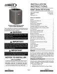
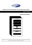
13ACD SPLIT SYSTEM AIR CONDITIONER
WITH DRY NITROGEN HOLDING CHARGE
INSTALLATION / START−UP INSTRUCTIONS
These instructions must be read and understood completely before attempting installation.
TABLE OF CONTENTS
Shipping and Packing List . . . . . . . . . . . . . . . . . . . . . . . . 3
General . . . . . . . . . . . . . . . . . . . . . . . . . . . . . . . . . . . . . . . . 2
Unit Dimensions . . . . . . . . . . . . . . . . . . . . . . . . . . . . . . . . . 2
Torque Requirements . . . . . . . . . . . . . . . . . . . . . . . . . . . . 3
Typical Unit Parts Arrangement . . . . . . . . . . . . . . . . . . . 2
Operating Gauge Set and Service Valves . . . . . . . . . . . 3
Recovering Refrigerant from Existing System . . . . . . . 4
New Outdoor Unit Placement . . . . . . . . . . . . . . . . . . . . . 5
Replacement Line Set . . . . . . . . . . . . . . . . . . . . . . . . . . . 6
Brazing Connections . . . . . . . . . . . . . . . . . . . . . . . . . . .
7
Removing Existing Metering Device and Flushing Line
Set and Indoor Coil . . . . . . . . . . . . . . . . . . . . . . . . . . . . 10
Installing New Indoor Metering Device . . . . . . . . . . . . 11
Leak Test Line Set and Indoor Coil . . . . . . . . . . . . . . . 12
Evacuating Line Set, Indoor Coil and Outdoor Unit . 13
Electrical Connections . . . . . . . . . . . . . . . . . . . . . . . . . . 14
Servicing Outdoor Unit Delivered Void of Nitrogen
Charge . . . . . . . . . . . . . . . . . . . . . . . . . . . . . . . . . . . . . . . . 15
Unit Start−Up and Weigh−In Charging . . . . . . . . . . . . . . 15
Optimizing System Charge . . . . . . . . . . . . . . . . . . . . . . 16
Maintenance . . . . . . . . . . . . . . . . . . . . . . . . . . . . . . . . . . 19
Start−Up and Performance Checklist . . . . . . . . . . . . . . . 20
NOTICE TO INSTALLER
This unit is factory−charged with dry nitrogen. The unit is intended for installation in existing HCFC−22
systems. Carefully follow all installation procedures.
WARNING
Installation or repairs made by unqualified persons can result in hazards to you and others. Installation
MUST conform with local building codes or, in the absence of local codes, with the National Electrical Code
NFPA 70/ANSI C1−1993 or current edition and Canadian Electrical Code Part 1 CSA C22.1.
CAUTION
Improper selection of a matching indoor unit and a matching metering device, improper installation, adjustment, alteration, service or maintenance may void the warranty. The qualified installer or agency must use
factory−authorized kits or accessories when modifying this products. Refer to the individual instructions
packaged with the kits or accessories when installing.
NOTE
These instructions are intended as a general guide and do not supersede national, state or local codes in any way.
These instructions must be left with the property owner.
11/10
*2P1110*
Page 1
506694−01
*P506694-01*
designed for use with HCFC−22 refrigerant only;
designed for use in systems that use either a RFC
device (orifice) included with outdoor unit or thermal
expansion valve (TXV). See the 13ACD product
specification sheet for approved fixed orifice sizes and
expansion valve kit match ups.
Important The air conditioning unit must have properly
matched system components including indoor unit and
refrigerant metering device. Mismatched equipment may
have an impact on the operation, performance, reliability,
and warranty? of the air conditioning unit.
General
The 13ACD air conditioner, which will also be referred to in
this instruction as the outdoor unit, uses HCFC−22
refrigerant. This outdoor unit is intended as a replacement
outdoor component for use in residential systems which
include an existing indoor coil which is functioning properly.
It is NOT intended for new installations.
This outdoor unit is:
shipped from the factory with nitrogen holding
charge that must be purged from the unit;
Unit Dimensions − Inches (mm)
A
A
OUTDOOR COIL FAN
Discharge Air
COMPRESSOR
B
SUCTION AND LIQUID LINE
CONNECTIONS
SIDE VIEW
OPTIONAL UNIT STAND-OFF KIT
(4) (FIELD−INSTALLED)
SIDE VIEW
Model Number
A
B
13ACD−018−230
24−1/4 (616)
25−1/4 (641)
13ACD−024−230
24−1/4 (616)
25−1/4 (641)
13ACD−030−230
24−1/4 (616)
33−1/4 (845)
13ACD−036−230
24−1/4 (616)
33−1/4 (845)
13ACD−042−230
28−1/4 (718)
29−1/4 (743)
13ACD−048−230
28−1/4 (718)
37−1/4 (946)
13ACD−060−230
28−1/4 (718)
33−1/4 (845)
Typical Unit Parts Arrangement
CONTROL BOX
NOTE: PLUMBING LAYOUT
MAY VARY SLIGHTLY BETWEEN MODEL SIZES.
GROUND LUG
SINGLE −POLE
CONTACTOR (K1)
DUAL RUN
CAPACITOR (C12)
LIQUID LINE
SERVICE VALVE
Figure 1. Typical Unit Parts Arrangement
Page 2
506694−01 11/10
SUCTION LINE
SERVICE VALVE
Shipping and Packing List
Operating Gauge Set and Service Valves
Check the unit for shipping damage. If damaged, or if parts
are missing, immediately contact the last shipping carrier.
1 Assembled 13ACD unit
1 Refrigerant flow control (RFC) kit (orifice) (see table 3
on page 12 for a complete list of available fixed orifice kits
USING MANIFOLD GAUGE SET
When checking the system charge, only use a manifold
gauge set that features low−loss anti−blow back fittings.
OPERATING SERVICE VALVES
The liquid and vapor line service valves are used for
removing refrigerant, flushing, leak testing, evacuating,
checking charge and charging.
Each valve is equipped with a service port which has a
factory−installed valve core. Figure 2 provides information
on accessing and operating both angle and ball−type
service valves.
Torque Requirements
When servicing or repairing HVAC components, ensure
the fasteners and caps are appropriately tightened. Table 1
lists torque values for fasteners.
Table 1. Torque Requirements
Parts
Recommended Torque
Service valve cap
8 ft.− lb.
11 NM
Sheet metal screws
16 in.− lb.
2 NM
Machine screws #10
28 in.− lb.
3 NM
Compressor bolts
90 in.− lb.
10 NM
Gauge port seal cap
8 ft.− lb.
11 NM
Operating Angle−Type
Service Valve:
To prevent stripping of the various caps used, the
appropriately sized wrench should be used and fitted
snugly over the cap before tightening.
ANGLE−TYPE SERVICE VALVE
(BACK−SEATED OPENED)
SERVICE PORT
CAP
1. Remove stem cap with
appropriately sized wrench.
IMPORTANT
SERVICE PORT CORE
an
(VALVE STEM SHOWN
OPEN)
INSERT HEX WRENCH
HERE
2. Use a service wrench with a
hex−head extension (3/16" for
liquid line valve sizes and 5/16"
for vapor line valve sizes) to back
the stem out counterclockwise as
far as it will go.
TO INDOOR
STEM
CAP
UNIT
TO OUTDOOR
UNIT
When service valve stem is OPEN, the service
port is open to line set, indoor and outdoor unit.
When service valve stem is
CLOSED, the service port is
open to the line set and indoor
unit.
A service port cap protects the service port core from contamination and
serves as the primary leak seal.
1. Remove stem cap with an appropriately sized wrench.
2. Use an appropriately sized wrenched to open. To open valve,
rotate stem counterclockwise 90°. To close rotate stem
clockwise 90°.
TO INDOOR UNIT
TO CLOSE ROTATE STEM
CLOCKWISE 90°.
(VALVE STEM SHOWN
CLOSED) INSERT HEX
WRENCH HERE
To Access Service Port:
Operating Ball−Type Service Valve:
TO OPEN ROTATE STEM
COUNTERCLOCKWISE 90°.
ANGLE−TYPE SERVICE VALVE
(FRONT−SEATED CLOSED)
BALL (SHOWN
CLOSED)
1. Remove service port cap with an appropriately sized wrench.
1/6 TURN
2. Connect gauge set to service port.
3. When testing is completed, replace service port cap
and tighten as follows:
With torque wrench: Finger tighten and torque cap
per table 1.
Without torque wrench: Finger tighten and use an
appropriately sized wrench to turn an additional
1/6 turn clockwise.
VALVE
STEM
11 12
10
9
8
7 6
Reinstall Stem Cap:
SERVICE PORT
CORE
SERVICE PORT
CAP
TO OUTDOOR
UNIT
STEM CAP
Without Torque Wrench: Finger tighten and use an
appropriately sized wrench to turn an additional
1/12 turn clockwise.
5
2
3
4
1/12 TURN
Stem cap protects the valve stem from damage and serves as
the primary seal. Replace the stem cap and tighten as follows:
With Torque Wrench: Finger tighten and then torque
11
cap per table 1.
10
SERVICE PORT
1
9
8
12 1
7 6 5
2
3
4
Figure 2. Operating Angle and Ball−Type Service Valves
Page 3
13ACD SERIES
Recovering Refrigerant from Existing System
IMPORTANT
The Clean Air Act of 1990 bans the intentional venting of refrigerant (CFCs, HCFCs AND HFCs) as of July 1, 1992.
Approved methods of recovery, recycling or reclaiming must be followed. Fines and/or incarceration may be levied for
noncompliance.
RECOVERING
1
REFRIGERANT FROM SYSTEM
DISCONNECT POWER
2
Disconnect all power to the existing outdoor unit at the service
disconnect switch or main fuse box/breaker panel.
CONNECT MANIFOLD GAUGE SET
Connect a gauge set, clean recovery cylinder and a recovery
machine to the service ports of the existing unit. Use the
instructions provided with the recovery machine to make the
connections.
SERVICE
DISCONNECT
SWITCH
MANIFOLD GAUGES
RECOVERY MACHINE
LOW
3
RECOVERING REFRIGERANT
Remove existing refrigerant using one of the following procedures:
CLEAN RECOVERY
CYLINDER
HIGH
OUTDOOR UNIT
IMPORTANT Some system configurations may contain higher than normal refrigerant charge due to either large internal coil volumes,
and/or long line sets.
METHOD 1:
Use this method if the existing outdoor unit is not equipped with shut−off valves, or if the unit is not operational and you plan to use the existing
refrigerant to flush the system.
Remove all refrigerant from the existing system. Check gauges after shutdown to confirm that the entire system is completely void of refrigerant.
METHOD 2:
Use this method if the existing outdoor unit is equipped with manual shut−off valves, and you plan to use new refrigerant to flush the system.
The following devices could prevent full system charge recovery into the outdoor unit:
Outdoor unit’s high or low−pressure switches (if applicable) when tripped can cycle the compressor OFF.
Compressor can stop pumping due to tripped internal pressure relief valve.
Compressor has internal vacuum protection that is designed to unload the scrolls (compressor stops pumping) when the pressure ratio meets
a certain value or when the suction pressure is as high as 20 psig. (Compressor suction pressures should never be allowed to go into a vacuum.
Prolonged operation at low suction pressures will result in overheating of the scrolls and permanent damage to the scroll tips, drive bearings and
internal seals.)
Once the compressor cannot pump down to a lower pressure due to one of the above system conditions, shut off the vapor valve. Turn OFF the
main power to unit and use a recovery machine to recover any refrigerant left in the indoor coil and line set.
Perform the following task:
A
Start the existing system in the cooling mode and close the liquid line valve.
B
Use the compressor to pump as much of the existing HCFC−22 refrigerant into the outdoor unit until the outdoor system is full. Turn the outdoor unit
main power OFF and use a recovery machine to remove the remaining refrigerant from the system.
NOTE It may be necessary to bypass the low pressure switches (if equipped) to ensure complete refrigerant evacuation.
C
D
When the low side system pressures reach 0 psig, close the vapor line valve.
Check gauges after shutdown to confirm that the valves are not allowing refrigerant to flow back into the low side of the system.
Figure 3. Refrigerant Recovery
Page 4
506694−01 11/10
New Outdoor Unit Placement
Remove existing outdoor unit prior to placement of new outdoor unit. See Unit Dimensions on page 2 for sizing mounting
slab, platforms or supports. Refer to figure 4 for mandatory installation clearance requirements.
MINIMUM CLEARANCE
ABOVE UNIT
CLEARANCE ON ALL SIDES INCHES (MILLIMETERS)
6 (152)
ACCESS PANEL
NOTES:
30 (762)
12 (305)
36 (914)
Clearance to one of the other three
sides must be 36 inches (914mm).
48 (1219)
Clearance to one of the remaining
two sides may be 12 inches
(305mm) and the final side may be
6 inches (152mm).
LINE SET
CONNECTIONS
MINIMUM CLEARANCE BETWEEN
TWO UNITS
24 (610)
Figure 4. Installation Clearances
DETAIL A
DETAIL B
Install unit level or, if on a slope, maintain slope tolerance of 2 degrees
(or 2 inches per 5 feet [50 mm per 1.5 m]) away from building
structure.
Install unit away
from windows .
STRUCTURE
DISCHARGE AIR
Two 90° elbows
installed in line set will
reduce line set vibration.
MOUNTING SLAB MUST SLOPE
AWAY FROM BUILDING.
GROUND LEVEL
Figure 5. Placement, and Slab Mounting
Page 5
13ACD SERIES
POSITIONING CONSIDERATIONS
NOTICE
CAUTION
Roof Damage!
This system contains both refrigerant and oil. Some
rubber roofing material may absorb oil and cause the
rubber to swell when it comes into contact with oil. The
rubber will then bubble and could cause leaks. Protect
the roof surface to avoid exposure to refrigerant and oil
during service and installation. Failure to follow this
notice could result in damage to roof surface.
In order to avoid injury, take proper precaution when lifting heavy objects.
CAUTION
Physical contact with metal edges and corners while
applying excessive force or rapid motion can result in
personal injury. Be aware of, and use caution when
working near these areas during installation or while
servicing this equipment.
Replacement Line Set
Consider the following when positioning the unit:
Some localities are adopting sound ordinances based
on the unit’s sound level registered from the adjacent
property, not from the installation property. Install the
unit as far as possible from the property line.
When possible, do not install the unit directly outside
a window. Glass has a very high level of sound
transmission. For proper placement of unit in relation
to a window see the provided illustration in figure 5.
PLACING OUTDOOR UNIT ON SLAB
When installing a unit at grade level, the top of the slab
should be high enough above the grade so that water from
higher ground would not collect around the unit as
illustrated in figure 5.
Slab may be level or have a slope tolerance away from the
building of not more than two degrees, or 2 inches per 5
feet (51 mm per 1524 mm) as illustrated in figure 5.
INSTALLING OUTDOOR UNIT ON ROOF
Install the unit at a minimum of 4 inches (102 mm) above
the surface of the roof. Ensure the weight of the unit is
properly distributed over roof joists and rafters. Redwood
or steel supports are recommended.
This section provides information on replacement of
existing line set. If replacement line set is not required,
then proceed to Brazing Connections on page 7.
REFRIGERANT LINE SET
Field refrigerant piping consists of liquid and suction lines
from the outdoor unit (braze connections) to the indoor unit
coil (flare or braze connections). If replacing line set, use
brazed, non−flare line set, or field−fabricated refrigerant
lines as listed in table 2.
Existing line set should meet size requirements listed in
table 2.
NOTE − When installing refrigerant lines longer than 50
feet, contact technical support for assistance. To obtain the
correct information from manufacturer, be sure to
communicate the following points:
Model (13ACD) and size of unit (e.g. −060).
Number of elbows and if there is a rise or drop of the
piping.
Line set diameters for the unit being installed as listed
in table 2 and total length of installation.
Table 2. Refrigerant Line Set Inches (mm)
Model
Field Connections
Recommended Line Set
Liquid Line
Suction Line
Liquid Line
Suction Line
3/8 in. (10 mm)
3/4 in. (19 mm)
3/8 in. (10 mm)
3/4 in. (19 mm)
3/8 in. (10 mm)
7/8 in. (22 mm)
3/8 in. (10 mm)
7/8 in. (22 mm)
3/8 in. (10 mm)
1−1/8 in. (29 mm)
3/8 in. (10 mm)
1−1/8 in. (29 mm)
Line Sets
13ACD−018−230
13ACD−024−230
13ACD−030−230
13ACD−036−230
13ACD−042−230
Field−fabricated brazed, non−flare.
13ACD−048−230
13ACD−060−230
Page 6
506694−01 11/10
Brazing Connections
Use the procedures outline in figures 6 and 7 for brazing
line set connections to service valves.
IMPORTANT
Use silver alloy brazing rods with 5% minimum silver
alloy for copper−to−copper brazing. Use 45% minimum
alloy for copper−to−brass and copper−to−steel brazing.
WARNING
When using a high pressure gas such as
dry nitrogen to pressurize a refrigeration
or air conditioning system, use a
regulator that can control the pressure
down to 1 or 2 psig (6.9 to 13.8 kPa).
WARNING
Danger of fire. Bleeding the refrigerant
charge from only the high side may result
in pressurization of the low side shell and
suction tubing. Application of a brazing
torch to a pressurized system may result
in ignition of the refrigerant and oil
mixture − Check the high and low
pressures before applying heat.
CAUTION
Brazing alloys and flux contain materials which are
hazardous to your health.
Avoid breathing vapors or fumes from brazing
operations. Perform operations only in well−ventilated
areas.
Wear gloves and protective goggles or face shield to
protect against burns.
Wash hands with soap and water after handling brazing
alloys and flux.
IMPORTANT
Allow braze joint to cool before removing the wet rag
from the service valve. Temperatures above 250ºF can
damage valve seals.
Page 7
13ACD SERIES
1
CUT AND DEBUR
Cut ends of the refrigerant lines square (free from nicks or dents)
and debur the ends. The pipe must remain round. Do not crimp end
of the line.
2
CAP AND CORE REMOVAL
Remove service cap and core from both the
vapor and liquid line service ports.
CUT AND DEBUR
SERVICE PORT
CAP
SERVICE
PORT
CORE
LINE SET SIZE MATCHES
SERVICE VALVE CONNECTION
SERVICE
PORT
CORE
SERVICE VALVE
CONNECTION
SERVICE
PORT CAP
COPPER TUBE
STUB
LIQUID LINE SERVICE
VALVE
REDUCER
SUCTION / VAPOR LINE
SERVICE VALVE
LINE SET SIZE IS SMALLER
THAN CONNECTION
DO NOT CRIMP SERVICE VALVE
CONNECTOR WHEN PIPE IS
SMALLER THAN CONNECTION
REFRIGERANT LINE
3
ATTACH THE MANIFOLD GAUGE SET FOR BRAZING LINE SETS TO LIQUID AND SUCTION / VAPOR
LINE SERVICE VALVES
Flow regulated nitrogen (at 1 to 2 psig) through the low−side refrigeration gauge set into the liquid line service port valve, and out of the suction /
vapor line service port valve.
A Connect gauge set low pressure side to
liquid line service valve (service port).
USE REGULATOR TO FLOW
B
Connect gauge set center port to bottle of
nitrogen with regulator.
C
Remove Schrader valve in suction / vapor
line service port to allow nitrogen to escape.
SUCTION / VAPOR SERVICE PORT MUST BE
OPEN TO ALLOW EXIT POINT FOR NITROGEN
C
LOW
HIGH
NITROGEN AT 1 TO 2 PSIG.
ATTACH
GAUGES
B
SUCTION /
VAPOR LINE
SERVICE
VALVE
VAPOR LINE
OUTDOOR
UNIT
INDOOR
UNIT
NITROGEN
LIQUID LINE
LIQUID LINE SERVICE
VALVE
A
WHEN BRAZING LINE SET TO
SERVICE VALVES, POINT FLAME
AWAY FROM SERVICE VALVE.
Figure 6. Brazing Procedures
Page 8
506694−01 11/10
4
5
6
WRAP SERVICE VALVES
To help protect service valve seals during brazing, wrap a saturated cloth around service valve bodies and copper tube stub. Use another
saturated cloth underneath the valve body to protect the base paint.
FLOW NITROGEN
Flow regulated nitrogen (at 1 to 2 psig) through the refrigeration gauge set into the valve stem port connection on the liquid service valve and
out of the suction / vapor valve stem port. See steps 3A, 3B and 3C on manifold gauge set connections.
BRAZE LINE SET
Wrap both service valves with a saturated cloth as illustrated here before brazing to line set.
LIQUID LINE SERVICE VALVE
WHEN BRAZING LINE SET TO
SERVICE VALVES, POINT FLAME
AWAY FROM SERVICE VALVE.
IMPORTANT Allow
braze joint to cool. Apply
additional saturated cloths to help cool brazed joint.
Do not remove wet rag until piping has cooled.
Temperatures above 250ºF will damage valve seals.
SATURATED CLOTH
LIQUID LINE
WARNING
SUCTION / VAPOR LINE
SERVICE VALVE
1. FIRE, PERSONAL INJURY, OR PROPERTY
DAMAGE will result if you do not wrap a wet cloth
around both liquid and suction line service valve
bodies and copper tube stub while brazing in the line
set! The braze, when complete, must be quenched
with water to absorb any residual heat.
2. Do not open service valves until refrigerant lines and
indoor coil have been leak−tested and evacuated.
Refer to procedures provided in this supplement.
WHEN BRAZING LINE SET TO
SERVICE VALVES, POINT FLAME
AWAY FROM SERVICE VALVE.
SUCTION / VAPOR LINE
SATURATED CLOTH
7
PREPARATION FOR NEXT STEP
After all connections have been brazed, disconnect manifold gauge set from service ports. Apply saturated rags to both service valves to cool
piping. Once piping is cool, remove all wet cloths.
Figure 7. Brazing Procedures (continued)
Page 9
13ACD SERIES
Removing Existing Metering Device and Flushing Line Set and Indoor Coil
Flushing is only recommended if existing indoor coil and line set are to be used. Otherwise proceed to Installing Indoor
Metering Device on page 11.
1A
1B
TYPICAL EXISTING FIXED ORIFICE
REMOVAL PROCEDURE
OR
(UNCASED COIL SHOWN)
TYPICAL EXISTING EXPANSION VALVE
REMOVAL PROCEDURE (UNCASED COIL
SHOWN)
STUB END
TWO PIECE PATCH PLATE
(UNCASED COIL ONLY)
DISTRIBUTOR TUBES
LIQUID LINE ORIFICE HOUSING
DISTRIBUTOR
TUBES
LIQUID LINE
ORIFICE
HOUSING
EXPANSION
VALVE
TEFLON®
RING
TEFLON® RING
FIXED ORIFICE
BRASS NUT
DISTRIBUTOR
ASSEMBLY
A
B
C
D
E
TEFLON®
RING
DISTRIBUTOR
ASSEMBLY
LIQUID LINE ASSEMBLY
(INCLUDES STRAINER)
On fully cased coils, remove the coil access and plumbing panels.
Remove any shipping clamps holding the liquid line and distributor
assembly.
Using two wrenches, disconnect liquid line from liquid line orifice
housing. Take care not to twist or damage distributor tubes during
this process.
Remove and discard fixed orifice, valve stem assembly if present
and Teflon® washer as illustrated above.
Use a field−provided fitting to temporarily reconnect the liquid line to
the indoor unit’s liquid line orifice housing.
2
A
1
MALE EQUALIZER
LINE FITTING
SENSING BULB
A
B
C
OPENED
EXISTING
INDOOR
UNIT
F
G
H
HIGH
NEW
OUTDOOR
UNIT
VAPOR LINE
SERVICE VALVE
D
E
GAUGE
MANIFOLD
LOW
CLOSED
3
B
LIQUID LINE SERVICE
VALVE
TANK
RETURN
VAPOR
LIQUID
D
RECOVERY
CYLINDER
A
B
C
D
C
EQUALIZER
LINE
LIQUID LINE
ASSEMBLY WITH
BRASS NUT
CONNECT GAUGES AND EQUIPMENT FOR
FLUSHING PROCEDURE
INVERTED CYLINDER
CONTAINS CLEAN
LIQUID HCFC−22 TO BE
USED FOR FLUSHING.
INLET
DISCHARGE
RECOVERY MACHINE
Inverted HCFC−22 cylinder with clean refrigerant to the vapor service
valve.
HCFC−22 gauge set (low side) to the liquid line valve.
HCFC−22 gauge set center port to inlet on the recovery machine with an
empty recovery tank to the gauge set.
Connect recovery tank to recovery machine per machine instructions.
Page 10
VAPOR
LINE
LIQUID
LINE
On fully cased coils, remove the coil access and plumbing panels.
Remove any shipping clamps holding the liquid line and distributor
assembly.
Disconnect the equalizer line from the expansion valve equalizer line
fitting on the vapor line.
Remove the vapor line sensing bulb.
Disconnect the liquid line from the expansion valve at the liquid line
assembly.
Disconnect the expansion valve from the liquid line orifice housing.
Take care not to twist or damage distributor tubes during this process.
Remove and discard expansion valve and the two Teflon® rings.
Use a field−provided fitting to temporary reconnect the liquid line to the
indoor unit’s liquid line orifice housing.
FLUSHING LINE SET
The line set and indoor unit coil must be flushed with at least the
same amount of clean refrigerant that previously charged the
system. Check the charge in the flushing cylinder before
proceeding.
A
Set the recovery machine for liquid recovery and start the
recovery machine. Open the gauge set valves to allow the
recovery machine to pull a vacuum on the existing system line
set
B and indoor unit coil.
B
Invert the cylinder of clean refrigerant and open its valve to allow
liquid refrigerant to flow into the system through the vapor line
valve. Allow the refrigerant to pass from the cylinder and through
the line set and the indoor unit coil before it enters the recovery
machine.
C
After all of the liquid refrigerant has been recovered, switch the
recovery machine to vapor recovery so that all of the HCFC−22
vapor is recovered. Allow the recovery machine to pull the
system down to zero.
D
Close the valve on the inverted HCFC−22 drum and the gauge
set valves. Pump the remaining refrigerant out of the recovery
machine and turn the machine off.
Figure 8. Removing Metering Device and Flushing
506694−01 11/10
SENSING
LINE
Installing New Indoor Metering Device
This outdoor unit is designed for use in existing HCFC−22
systems that use either a fixed orifice (RFC) or expansion
valve metering device (purchased separately) at the
indoor coil.
1A
INDOOR EXPANSION VALVE
INSTALLATION
(Uncased Coil Shown)
TWO PIECE
PATCH PLATE
(UNCASED
COIL ONLY)
DISTRIBUTOR
TUBES
LIQUID LINE
ORIFICE
HOUSING
See the 13ACD product specification sheet for approved
fixed orifice sizes and expansion valve kit match ups. The
expansion valve unit can be installed internal or external to
the indoor coil.
A
B
STUB
END EXPANSION
VALVE
TEFLON®
RING
TEFLON®
RING
C
D
SENSING
LINE
E
DISTRIBUTOR
ASSEMBLY
EQUALIZER
LINE
1/8 Turn
SENSING BULB INSTALLATION
LIQUID LINE
ASSEMBLY WITH
BRASS NUT
MALE EQUALIZER LINE
FITTING (SEE
EQUALIZER LINE
INSTALLATION FOR
FURTHER DETAILS)
1/2 Turn
Remove the field−provided fitting that temporarily
reconnected the liquid line to the indoor unit’s
distributor assembly.
11 12 1
2
10
Install one of the provided Teflon® rings around the
9
3
stubbed end of the expansion valve and lightly
4
8
lubricate the connector threads and expose surface of
5
7
6
the Teflon® ring with refrigerant oil.
Attach the stubbed end of the expansion valve to the
liquid line orifice housing. Finger tighten and use an
appropriately sized wrench to turn an additional 1/2 turn clockwise as
illustrated in the figure above, or 20 ft−lb.
Place the remaining Teflon® washer around the other end of the expansion
valve. Lightly lubricate connector threads and expose surface of the
Teflon® ring with refrigerant oil.
Attach the liquid line assembly to the expansion valve. Finger tighten and
use an appropriately sized wrench to turn an additional 1/2 turn clockwise
as illustrated in the figure above or 20 ft−lb.
A
Attach the vapor line sensing bulb in the proper
orientation as illustrated to the right using the clamp
and screws provided.
NOTE Confirm proper thermal contact between vapor
line and expansion bulb before insulating the sensing bulb
once installed.
VAPOR
LINE
LIQUID LINE
B
Sensing bulb insulation is required if
mounted external to the coil casing. sensing
bulb installation for bulb positioning.
11 12 1
2
10
9
3
4
8
7 6 5
Connect the equalizer line from the expansion valve to the equalizer
vapor port on the vapor line. Finger tighten the flare nut plus 1/8 turn (7
ft−lbs) as illustrated below.
ON LINES SMALLER THAN
7/8", MOUNT SENSING
BULB AT EITHER THE 3 OR
9 O’CLOCK POSITION.
VAPOR LINE
EQUALIZER LINE INSTALLATION
BULB
12
BULB
Remove and discard either the flare seal cap or flare nut with copper flare
seal bonnet from the equalizer line port on the vapor line as illustrated in the
figure below.
NOTE NEVER
MOUNT ON BOTTOM
OF LINE.
VAPOR LINE
FLARE SEAL CAP
ON 7/8" AND LARGER LINES,
MOUNT SENSING BULB AT
EITHER THE 4 OR 8 O’CLOCK
POSITION. NEVER MOUNT ON
BOTTOM OF LINE.
FLARE NUT
12
OR
COPPER FLARE
SEAL BONNET
MALE BRASS EQUALIZER
LINE FITTING
VAPOR LINE
BULB
BULB
FIXED ORIFICE (RFC)
DEVICE INSTALLATION
1B
TEFLON® RING
FIXED ORIFICE
SEE TABLE 3 FOR
INDOOR FIXED
ORIFICE KITS CATALOG
NUMBERS.
BRASS NUT
DISTRIBUTOR TUBES
LIQUID LINE ORIFICE HOUSING
REMOVE AND DISCARD WHITE
TEFLON® SEAL (IF PRESENT)
Figure 9. Installing Indoor Metering Device
Page 11
13ACD SERIES
Table 3. Indoor Fixed Orifice Kits
IMPORTANT
Model
Catalog
Number
Part Number
Drill Size
018
024
10W95
98M12
100484−07
100484−12
0.055
0.062
030
036
11W00
98M78
100484−16
100484−24
0.067
0.076
042
10W86
100484−28
0.080
048
98M14
100484−36
0.089
060
98M15
100484−45
0.099
The Environmental Protection Agency (EPA) prohibits
the intentional venting of HCFC refrigerants during
maintenance, service, repair and disposal of appliance.
Approved methods of recovery, recycling or reclaiming
must be followed.
WARNING
Leak Test Line Set and Indoor Coil
After completing the leak testing of the line set and indoor
coil as outlined in figure 10, proceed to Evacuating Line Set
and Indoor Coil on page 13.
1
Refrigerant can be harmful if it is inhaled. Refrigerant
must be used and recovered responsibly.
Failure to follow this warning may result in personal injury
or death.
CONNECT GAUGE SET
A
Connect an HCFC−22 manifold gauge set high pressure hose
to the vapor valve service port.
LOW
NOTE Normally, the high pressure hose is connected to
the liquid line port. However, connecting it to the vapor port
better protects the manifold gauge set from high pressure
damage.
With both manifold valves closed, connect the cylinder of
HCFC−22 refrigerant to the center port of the manifold gauge
set.
B
NOTE Later in the procedure,
the HCFC−22 container will be
replaced by the nitrogen
container.
HIGH
MANIFOLD GAUGE SET
OUTDOOR UNIT
A
B
IMPORTANT Leak detector
must be capable of sensing
HCFC−22 refrigerant.
TO VAPOR
SERVICE VALVE
HCFC−22
NITROGEN
2
TEST FOR LEAKS
DIGITAL SCALE
After the line set has been connected to the indoor and outdoor units, check the line set connections and indoor unit for leaks. Use
the following procedure to test for leaks:
A
With both manifold valves closed, connect the cylinder of HCFC−22 refrigerant to the center port of the manifold gauge set. Open the
valve on the HCFC−22 cylinder (vapor only).
B
Open the high pressure side of the manifold to weigh in a trace amount of HCFC−22 into the line set and indoor unit. A trace amount is a
maximum of two ounces (57 g) refrigerant or three pounds (31 kPa) pressure. Close the valve on the HCFC−22 cylinder and the valve
on the high pressure side of the manifold gauge set. Disconnect the HCFC−22 cylinder.
C
Connect a cylinder of dry nitrogen with a pressure regulating valve to the center port of the manifold gauge set.
D
Adjust dry nitrogen pressure to 150 psig (1034 kPa). Open the valve on the high side of the manifold gauge set in order to pressurize the line
set and the indoor unit.
E
After a few minutes, open one of the service valve ports and verify that the refrigerant added to the system earlier is measurable with a
leak detector.
F
After leak testing, disconnect gauges from service ports.
Figure 10. Leak Test
IMPORTANT
Leak detector must be capable of sensing HCFC−22 refrigerant.
Page 12
506694−01 11/10
Evacuating Line Set, Indoor Coil and Outdoor Unit
CONNECT GAUGE SET
1
LOW
NOTE Remove cores from service valves (if not already done).
Connect low side of manifold gauge set
with 1/4 SAE in−line tee to vapor line
service valve
HIGH
Connect high side of manifold gauge set
to liquid line service valve
Connect micron gauge available
connector on the 1/4 SAE in−line tee.
OUTDOOR
UNIT
A
MANIFOLD
GAUGE SET
A34000 1/4 SAE TEE WITH
SWIVEL COUPLER
500
Connect the vacuum pump (with
vacuum gauge) to the center port of the
manifold gauge set. The center port line
will be used later for both the HCFC−22
and nitrogen containers.
MICRON
GAUGE
C
TO VAPOR
SERVICE VALVE
NITROGEN
HCFC−22
B
VACUUM PUMP
TO LIQUID LINE
SERVICE VALVE
D
2
EVACUATE THE SYSTEM
A
B
C
RECOMMEND MINIMUM 3/8" HOSE
Open the liquid and vapor line service valves (counterclockwise) to release the factory nitrogen charge (contained in outdoor unit) into the
system.
Open both manifold valves and start the vacuum pump.
Evacuate the line set, indoor unit and outdoor unit to an absolute pressure of 23,000 microns (29.01 inches of mercury).
NOTE During the early stages of evacuation, it is desirable to close the manifold gauge valve at least once. A rapid rise in pressure
indicates a relatively large leak. If this occurs, repeat the leak testing procedure.
NOTE The term absolute pressure means the total actual pressure within a given volume or system, above the absolute zero of
pressure. Absolute pressure in a vacuum is equal to atmospheric pressure minus vacuum pressure.
D
When the absolute pressure reaches 23,000 microns (29.01 inches of mercury), perform the following:
E
F
G
H
Close manifold gauge valves
Close valve on vacuum pump
Turn off vacuum pump
Disconnect manifold gauge center port hose from vacuum pump
Attach manifold center port hose to a dry nitrogen cylinder with pressure regulator set to 150 psig (1034 kPa) and purge the hose.
Open manifold gauge valves to break the vacuum in the line set and indoor unit.
Close manifold gauge valves.
Shut off the dry nitrogen cylinder and remove the manifold gauge hose from the cylinder. Open the manifold gauge valves to release the
dry nitrogen from the line set and indoor unit.
Reconnect the manifold gauge to the vacuum pump, turn the pump on, and continue to evacuate the line set and indoor unit until the
absolute pressure does not rise above 500 microns (29.9 inches of mercury) within a 20−minute period after shutting off the vacuum pump
and closing the manifold gauge valves.
When the absolute pressure requirement above has been met, disconnect the manifold hose from the vacuum pump and connect it to an
upright cylinder of HCFC−22 refrigerant. Open the manifold gauge valve 1 to 2 psig in order to release the vacuum in the line set and indoor
unit.
1/6 TURN
Perform the following:
Close manifold gauge valves.
12 1
11
Shut off HCFC−22 cylinder.
2
10
Reinstall service valve cores by removing manifold hose from service valve. Quickly install cores with core
tool while maintaining a positive system pressure.
Replace stem caps and secure finger tight, then tighten an additional one−sixth (1/6) of a turn as illustrated.
9
8
4
7
6
3
5
Figure 11. Evacuating System
Page 13
13ACD SERIES
Electrical
In the U.S.A., wiring must conform with current local codes
and the current National Electric Code (NEC). In Canada,
wiring must conform with current local codes and the current
Canadian Electrical Code (CEC).
nameplate for minimum circuit ampacity and maximum
overcurrent protection size.
24VAC TRANSFORMER
Use the transformer provided with the furnace or air
handler for low-voltage control power (24VAC − 40 VA
minimum)
Refer to the furnace or air handler installation instructions
for additional wiring application diagrams and refer to unit
SIZE CIRCUIT AND INSTALL DISCONNECT SWITCH
CHECK EXISTING ROOM THERMOSTAT
Refer to the unit nameplate for minimum circuit ampacity, and maximum
fuse or circuit breaker (HACR per NEC). Install power wiring and properly
sized disconnect switch.
Ensure that existing room thermostat is installed on an inside wall
approximately in the center of the conditioned area and 5 feet (1.5m) from
the floor. It should not be installed on an outside wall or where it can be
affected by sunlight or drafts.
MAIN FUSE BOX/
BREAKER PANEL
THERMOSTAT
SERVICE
DISCONNECT
SWITCH
5 FEET
(1.5M)
NOTE Units are approved for use only with copper conductors.
Ground unit at disconnect switch or to an earth ground.
NOTE 24VAC, Class II circuit connections are made in the control
panel.
HIGH VOLTAGE / GROUND WIRES
Any excess high voltage field wiring should be trimmed and secured away from any low voltage field wiring. To facilitate a conduit, a
cutout is located in the bottom of the control panel. Connect conduit to the control panel using a proper conduit fitting.
CONTROL WIRING
Use existing or replace low voltage wiring from outdoor to indoor unit and from thermostat to indoor unit as illustrated.
A
B
Run 24VAC control wires through hole with grommet and secure with provided wire tie.
Make 24VAC thermostat wire connections. Locate the two wires from the contactor and make connection using field provided wire nuts:
Black to Y1
NOTE For proper voltages, select thermostat wire (control wires)
gauge per table below.
Black to C (common)
TYPICAL LOW VOLTAGE CONTROL
WIRING
THERMOSTAT
NOTE Do not bundle any excess 24VAC control wires inside
control panel.
INDOOR UNIT
HIGH VOLTAGE
CONNECTIONS
(CONTACTOR)
POWER
R
R
HEAT
COOLING
G
BLACK
INDOOR
BLOWER
GROUND
A
GROMMET AND
WIRE TIE
C
C
BLACK
WIRE RUN LENGTH
AWG# INSULATION TYPE
LESS THAN 100’ (30 METERS)
18
MORE THAN 100’ (30 METERS) 16
TEMPERATURE RATING
HIGH VOLTAGE
FLEXIBLE CONDUIT
35ºC MINIMUM.
Page 14
506694−01 11/10
B
G
COMMON
C
FACTORY
WIRING
Y1
Y
Y
LOW VOLTAGE
FIELD WIRING
CONTROL
WIRING
OUTDOOR
UNIT
W
W1
SINGLE PHASE
HIGH VOLTAGE
FIELD WIRING
NOTE Wire tie provides low voltage control wire
strain relief and to maintain separation of field
installed low and high voltage circuits.
WARNING
Electric Shock Hazard. Can cause injury or death. Unit must be grounded in accordance with national and
local codes.
Line voltage is present at all components when unit is not in operation on units with single-pole contactors.
Disconnect all remote electric power supplies before opening access panel. Unit may have multiple power
supplies.
Figure 12. Typical Unit Wiring Diagram
IMPORTANT
If unit is equipped with a crankcase heater, it should be
energized 24 hours before unit start−up to prevent
compressor damage as a result of slugging.
6. Monitor the system to determine the amount of
moisture remaining in the oil. It may be necessary to
replace the filter drier several times to achieve the
required dryness level. If system dryness is not
verified, the compressor will fail in the future.
Unit Start−Up and Weigh−In Charging
Servicing Outdoor Unit Delivered Void of
Nitrogen Charge
1. Check that fan rotates freely.
If the outdoor unit is void of factory nitrogen charge, clean
the system using the procedure described below.
1. Use nitrogen to repressurize system and check for
leaks.
2. Evacuate the system using evacuating procedure
provided in this instruction.
3. Use nitrogen to break the vacuum and install a new
filter drier in the system.
4. Evacuate the system again using evacuating
procedure provided in this instruction.
5. Weigh in refrigerant using procedure outlined under
Unit Start−Up and Weigh−In Charging.
2. Inspect all factory− and field−installed wiring for loose
connections.
3. After evacuation of the outdoor unit, line set, and
indoor unit are complete, close the manifold gauge set
valves. Disconnect vacuum pump from center hose of
gauge set.
4. Connect the center hose of the gauge set to a cylinder
of HCFC−22 and purge the hose. Then, place the
cylinder upside down on a scale (see figure 14).
5. Open the high side manifold gauge valve and weigh in
liquid refrigerant. Refer to unit nameplate to determine
correct weigh−in charge (see figure 13).
6. Close manifold gauge valves.
Page 15
13ACD SERIES
WEIGH−IN CHARGING
ADD AMOUNT OF HCFC−22
REFRIGERANT AS SPECIFIED ON UNIT
NAMEPLATE
ADJUST AMOUNT FOR VARIATION IN
LINE SET LENGTH AS LISTED BELOW
TOTAL CHARGE
=
+
Refrigerant Charge per Line Set Length
Liquid Line
Set Diameter
Ounces per 5 feet (g per 1.5 m)
adjust from 15 feet (4.6 m) line set*
3/8" (9.5 mm)
3 ounce per 5’ (85 g per 1.5 m)
NOTE − *If line length is greater than 15 ft. (4.6 m), add this
amount. If line length is less than 15 ft. (4.6 m), subtract this
amount.
Figure 13. Gauge Set Charge Setup and Weigh In
1. Check voltage supply at the disconnect switch. The
voltage must be within the range listed on the unit’s
nameplate. If not, do not start the equipment until you
have consulted with the power company and the
voltage condition has been corrected.
NOTE Refrigerant tank should be turned right−side−up to
deliver vapor during charge optimizing procedure.
MANIFOLD GAUGE SET
LOW
HIGH
OUTDOOR
UNIT
2. Make sure the refrigerant cylinder is right−side−up
so that it will deliver gas during the charge
optimizing procedure.
REFRIGERANT
TANK
3. Set the thermostat for a cooling demand. Turn on
power to the indoor unit and close the outdoor unit
disconnect switch to start the unit.
SCALE
4. Allow unit to run for five minutes to allow pressures to
stabilize.
5. Check and adjust indoor airflow using procedure in
figure 15.
6. Use either approach, subcooling or superheat
method (see figures 16 and 17 for TXV system or
figure 18 for RFC system) to optimize system charge.
Adjust charge as necessary.
Figure 14. Gauge Set Charge Setup
Optimizing System Charge
This section outlines procedures for optimizing the system
charge.
NOTE Gauge set should be connected as illustrated in
figure 14; however, refrigerant tank should be turned
right−side−up to deliver refrigerant gas during charge
optimizing procedure.
Page 16
506694−01 11/10
7. Close gauge set valves and disconnect gauge set.
8. Replace the stem and service port caps and tighten as
specified in Operating Service Valves on page 3.
9. Recheck voltage while the unit is running. Power must
be within range shown on the nameplate.
1. Determine the desired DT Measure entering air
temperature using dry bulb (A) and wet bulb (B). DT is the
intersecting value of A and B in the table (see triangle).
AIRFLOW
Temp.
of air
entering
indoor
coil ºF
DT
72
20 20 19 18 17 17 16 15 15 14 13 12 11 10
70
Wet−bulb ºF
19 19 18 18 17 17 16 15 15 14 13 12 11 10
57 58 59 60 61 62 63 64 65 66 67 68 69 70
Dry−bulb
24
23
22
21
A
24
23
22
21
24
23
22
21
23
22
21
20
23
22
21
19
22
21
20
19
22
21
19
18
2. Find temperature drop across coil Measure the coil’s
80
78
76
74
22
20
19
17
20
19
18
16
19
18
17
16
18
17
16
15
17
16
15
14
16
15
14
13
15
14
13
12
dry bulb entering and leaving air temperatures (A and C).
Temperature Drop Formula: (TDrop) = A minus C.
3. Determine if fan needs adjustment If the difference
between the measured TDrop and the desired DT (TDrop–DT)
is within +3º, no adjustment is needed. See examples:
Assume DT = 15 and A temp. = 72º, these C temperatures
would necessitate stated actions:
Cº TDrop –
DT = ºF ACTION
B
C
53º
A
72º
TDrop
19º
air flow
DRY
BULB
INDOOR
COIL
All temperatures are
expressed in ºF
62º
B
64º
air flow
19
14
10
53º
58º
–
–
–
=
=
=
15
15
15
4 Increase the airflow
−1 (within +3º range) no change
−5 Decrease the airflow
4. Adjust the fan speed See indoor unit instructions to
DRY
BULB
increase/decrease fan speed.
Changing air flow affects all temperatures; recheck
temperatures to confirm that the temperature drop and DT are
within +3º.
WET
BULB
Figure 15. Checking Indoor Airflow over Evaporator Coil Using Delta−T Chart
Outdoor Ambient Temperature is 65ºF
(18.3ºC) or BELOW
1. Confirm proper airflow across coil using figure 15.
2. Compare unit pressures with table 4, Normal Operating Pressures.
3. Set thermostat to call for heat (must have a cooling load between 70-80ºF
(21−26ºC).
4. Connect gauge set.
5. Measure outdoor ambient temperature.
6. When heat demand is satisfied, set thermostat to call for cooling.
7. Allow temperatures and pressures to stabilize.
BLOCK OUTDOOR COIL: [sometimes necessary
with lower temperatures] Use cardboard or plastic
sheet to restrict the airflow through the outdoor coil to
achieve pressures from 325−375 psig (2240−2585
kPa). Higher pressures are needed to check charge.
Block equal sections of air intake panels and move
coverings sideways until the liquid pressure is in the
above noted ranges.
NOTE − If necessary, block outdoor coil to maintain 200−250 psig.
8. Record liquid line temperature (Position temperature sensor on liquid line near
liquid line service port.):
LIQº = ______
9. Measure liquid line pressure and use the value to determine saturation
temperature:
SATº = ______
10. Subtract to determine subcooling (SCº):
SATº_____ − LIQº _____ = SCº _____
11. Compare results with table below.
12. If value is greater than shown, remove refrigerant; if less than shown, add
refrigerant.
13. If refrigerant is added or removed, retest using approach method.
SCº (Subcooling) Values (F:+/−1.0° [C: +/−0.6°])
Model
°F (°C)*
−018
−024
−030
−036
−042
−048
−060
7 (3.8)
12 (6.7)
9 (5.0)
10 (5.6)
14 (8.0)
10 (5.6)
13 (7.2)
Figure 16. Subcooling Method (TXV)
Page 17
13ACD SERIES
1. Confirm proper airflow across coil using figure15.
2. Compare unit pressures with table 4, Normal Operating Pressures.
Outdoor Ambient Temperature 66ºF
(18.9ºC) or ABOVE.
3. Connect gauge set.
4. When heat demand is satisfied, set thermostat to call for cooling.
5. Allow temperatures and pressures to stabilize.
6. Record outdoor ambient temperature:
AMBº =_________
7. Record line temperature:
LIQº = __________
8. Subtract to determine approach (APPº):
LIQº_____ − AMBº _____ = APPº_____
9. Compare results with table below.
10. If value is greater than shown (high approach), add refrigerant; if less than shown
(liquid temperature too close to ambient temperature, low approach), remove
refrigerant.
11. If refrigerant is added or removed, retest to confirm that unit is properly charged.
APPº (Approach) Values(F:+/−1.0° [C: +/−0.6°])
Model
°F (°C)*
−018
−024
−030
−036
−042
−048
−060
6 (3.3)
6 (3.3)
8 (4.4)
12 (6.7)
5 (2.8)
6 (3.3)
7 (3.8)
Figure 17. Approach Method (TXV)
1. Confirm proper airflow across coil using figure 15.
2. Compare unit pressures with table 4, Normal Operating Pressures.
ABOVE Outdoor Ambient 40ºF (4.4ºC)
SHº (Superheat) Values (+/−5ºF)
Wet Bulb (air entering indoor coil)
ºF* 50 52 54 56 58 60 62 64 66 68 70 72 74 76
40 15 18 20 23 26 29 32 34 38 41 43 46 48 51
45 13 16 18 21 24 27 30 33 36 39 41 44 46 49
50
11 14 16 19 22 25 28 31 34 37 39 42 44 47
55
9 12 14 17 20 23 27 30 33 36 38 40 42 44
60
7 10 12 15 18 21 24 27 30 33 35 38 40 43
65
- 6 10 13 16 19 21 24 27 30 33 36 38 41
70
- - 7 10 13 16 19 21 24 27 30 33 36 39
75
- - - 6 9 12 15 18 21 24 28 31 34 37
80
- - - - 5 8 12 15 18 21 25 28 31 35
85
- - - - - - 8 11 15 19 22 26 30 33
90
- - - - - - 5 9 13 16 20 24 27 31
95
- - - - - - - 6 10 14 18 22 25 29
100 - - - - - - - - 8 12 16 21 24 28
105 - - - - - - - - 5 9 13 17 22 26
110 - - - - - - - - - 6 11 15 20 25
115 - - - - - - - - - - 8 14 18 24
* Dry−bulb temperature (ºF) of entering outdoor ambient air.
3. Set thermostat to call for heat (must have a cooling load between 70-80ºF
(21−26ºC).
4. Connect gauge set.
5. When heat demand is satisfied, set thermostat to call for cooling.
6. Allow temperatures and pressures to stabilize.
7. Measure the suction line pressure and use the value to determine
saturation temperature :
SATº =_________
8. Record suction line temperature. (Position temperature sensor on
suction line near suction line service port.)
VAPº =_________
9. Subtract to determine superheat (SHº):
VAPº − _____ SATº ______ = SHº______
10. Record the wet bulb temperature (air entering indoor coil):
WB =_______
11. Record outdoor ambient temperature.
12. Compare results with table to the left.
13. If value is greater than shown, add refrigerant; if less than shown, remove
refrigerant.
14. If refrigerant is added or removed, retest to confirm that unit is properly
charged
I
NOTE − Do not attempt to charge system where a dash appears in the table, system could be overcharged. Superheat is taken at suction line service
port. Suction line superheat must never be less than 5ºF at the suction line service port.
Figure 18. Superheat Method (RFC)
Page 18
506694−01 11/10
Table 4. Normal Operating Pressures (Liquid +10 and Suction +5 psig)
IMPORTANT
Use this table to perform maintenance checks; it is not a procedure for charging the
system. Minor variations in these pressures may be due to differences in installations.
Significant deviations could mean that the system is not properly charged or that a
problem exists with some component in the system.
13ACD
−018
−024
−030
−036
−042
−048
−060
5F (5C)*
Liquid / Suction
Liquid / Suction
Liquid / Suction
Liquid / Suction
Liquid / Suction
Liquid / Suction
Liquid / Suction
Expansion Valve (TXV)
65 (18)
138 / 79
148 / 79
147 / 75
155 / 79
147 / 78
144 / 77
152 / 73
70 (21)
148 / 80
160 / 79
159 / 75
169 / 80
158 / 78
152 / 77
164 / 75
75 (24)
160 / 80
174 / 80
172 / 76
183 / 81
172 / 79
163 / 78
177 / 77
80 (27)
174 / 81
188 / 81
186 / 77
199 / 81
189 / 79
179 / 78
192 / 78
85 (29)
188 / 81
203 / 81
201 / 77
215 / 82
205 / 80
195 / 79
208 / 79
90 (32)
204 / 81
220 / 82
216 / 78
233 / 82
222 / 81
212 / 80
225 / 80
95 (35)
219 / 82
236 / 83
233 / 79
252 / 83
241 / 81
229 / 80
243 / 80
100 (38)
236 / 82
253 / 83
250 / 80
271 / 83
259 / 82
245 / 81
261 / 81
105 (41)
253 / 83
272 / 84
268 / 80
291 / 84
279 / 82
265 / 81
280 / 82
110 (43)
272 / 84
291 / 85
287 / 81
311 / 85
299 / 83
287 / 82
299 / 83
115 (45)
291 / 84
311 / 85
306 / 82
331 / 86
320 / 84
309 / 83
320 / 83
Fixed Orifice (RFC)
65 (18)
139 / 67
147 / 71
148 / 65
162 / 75
158 / 72
151 / 71
152 / 68
70 (21)
149 / 70
159 / 73
161 / 67
174 / 76
170 / 75
161 / 73
165 / 71
75 (24)
161 /74
172 / 75
175 / 70
187 / 78
182 / 76
172 / 75
178 / 73
80 (27)
175 / 77
186 / 77
190 / 73
201 / 79
195 / 78
185 / 76
193 / 76
85 (29)
189 / 79
200 / 79
205 / 75
215 / 81
209 / 80
198 / 77
208 / 78
90 (32)
203 / 81
216 / 81
221 / 77
231 / 82
224 / 81
213 / 79
224 / 80
95 (35)
218 / 82
232 / 82
237 / 79
247 / 83
240 / 82
227 / 80
239 / 81
100 (38)
234 / 83
247 / 83
254 / 80
265 / 84
256 / 84
243 / 81
258 / 82
105 (41)
251 / 85
264 / 85
271 / 81
283 / 85
273 / 85
259 / 82
276 / 83
110 (43)
269 / 86
285 / 86
289 / 82
302 / 86
290 / 86
276 / 84
294 / 85
115 (45)
287 / 87
302 / 87
308 / 83
321 / 87
310 / 87
293 / 85
313 / 86
Maintenance
Maintenance and service must be performed by a qualified
installer or service agency. At the beginning of each
cooling season, the system should be checked as follows:
Outdoor Unit
1. Outdoor unit fan motor is pre−lubricated and sealed.
No further lubrication is needed.
2. Visually inspect all connecting lines, joints and coils for
evidence of oil leaks.
3. Check all wiring for loose connections.
4. Check for correct voltage at unit (unit operating).
5. Check amp draw on outdoor fan motor.
Motor Nameplate:_________ Actual:__________.
6. Inspect drain holes in coil compartment base and
clean if necessary.
NOTE - If insufficient cooling occurs, the unit should be
gauged and refrigerant charge should be checked.
Outdoor Coil
Clean and inspect outdoor coil (may be flushed with a
water hose). Ensure power is off before cleaning.
NOTE It may be necessary to flush the outdoor coil
more frequently if it is exposed to substances which are
corrosive or which block airflow across the coil (e.g., pet
urine, cottonwood seeds, fertilizers, fluids that may contain
high levels of corrosive chemicals such as salts)
Sea Coast Moist air in ocean locations can carry salt,
which is corrosive to most metal. Units that are located
near the ocean require frequent inspections and
maintenance. These inspections will determine the
necessary need to wash the unit including the outdoor coil.
Consult your installing contractor for proper
intervals/procedures for your geographic area or service
contract.
Indoor Unit
1. Clean or change filters.
2. Some blower motors are prelubricated and permanently
sealed. No more lubrication is needed.
3. Adjust blower speed for cooling. Measure the pressure
drop over the coil to determine the correct blower CFM.
Refer to the unit information service manual for pressure
drop tables and procedure.
4. Belt Drive Blowers − Check belt for wear and proper
tension.
5. Check all wiring for loose connections.
Page 19
13ACD SERIES
6. Check for correct voltage at unit. (blower operating)
Indoor Coil
1. Clean coil if necessary.
2. Check connecting lines, joints and coil for evidence of
oil leaks.
3. Check condensate line and clean if necessary.
7. Check amp draw on blower motor.
Motor Nameplate:_________ Actual:__________.
Start−Up and Performance Checklist
Job Name
Job no.
Date
Job Location
City
State
Installer
City
State
Unit Model No.
Serial No.
Service Technician
Nameplate Voltage
Rated Load Ampacity
Compressor
Outdoor Fan
Maximum Fuse or Circuit Breaker
Electrical Connections Tight? Indoor Filter clean? Supply Voltage (Unit Off)
Indoor Blower RPM
S.P. Drop Over Indoor (Dry)
Outdoor Coil Entering Air Temp.
Discharge Pressure
Suction Pressure
Refrigerant Charge Checked?
Outdoor Fan Checked?
Refrigerant Lines:
Leak Checked? Properly Insulated? Service Valves:
Fully Opened?
Caps Tight?
Thermostat
Calibrated? Properly Set? Level? Voltage With Compressor Operating
Page 20
506694−01 11/10