1
FREE
Min. 150mm
• • • Refrigerant
Min. 15mm
Service space
Min.15
Front trunking hole
(Knock-Out)
Power supply wiring hole
( 40 Knock-Out)
Front piping hole
(Knock-Out)
92
60
75
92
Power supply wiring hole
( 27 Knock-Out)
55
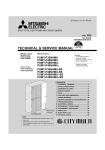
Piping Knock-Out Hole Details
GAS pipe connection (FLARE) 15.88 (5/8F)
2 • • • Refrigerant LIQUID pipe connection (FLARE) 9.52 (3/8F)
*1 • • • Indication of STOP VALVE connection location.
1
Example of Notes
Min. 1000mm
Min. 15mm
Right piping hole
(Knock-Out)
Power supply wiring hole
( 27 Knock-Out)
Handle for
moving
Min.500
92
29
75
Max.30
92
55
50
Right trunking hole
(Knock-Out)
Power supply wiring hole
( 40 Knock-Out)
Rear Air Intake
FOUNDATION
Rear trunking hole
(Knock-Out)
75
55
Handle for
moving
92
60
Side Air Intake
Rear piping hole
(Knock-Out)
92
Power supply wiring hole
( 40 Knock-Out)
Handle for
moving
Side Air Intake
Power supply wiring hole
( 27 Knock-Out)
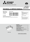
Piping and wiring connections
can be made from 4 directions:
FRONT, Right, Rear and Below.
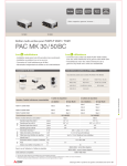
<Foundation bolt height>
4 PIPING-WIRING DIRECTIONS
3 FOUNDATION BOLTS
Please secure the unit firmly
with 4 foundation (M10<W3/8>) bolts.
(Bolts and washers must be
purchased locally.)
2 SERVICE SPACE
Dimensions of space needed
for service access are
shown in the below diagram.
1 FREE SPACE (Around the unit)
1338
The diagram below shows a basic example.
Explantion of particular details are
given in the installation manuals etc.
3
73 60
26
55
27
Min.150
Min.500
92
27
3
73 60
26
55
27
3
73 60
26
632
369
330
25
26
154
45
136
110
225
160
362
160
160
70
Drain hole
(5- 33)
Ground for the power supply
("GR"marking position)
1050
Air Discharge
Installation Feet
56
42
81
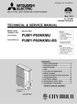
For the
branch box
power supply
2
1
Handle for
moving
Service panel
Ground for
the branch box
power supply
Bottom piping hole
(Knock-Out)
Air Intake
For the
transmission line
For concentration
control
Rear piping cover
Front piping cover
Ground for the transmission line
Ground for concentration control
For the
power supply
Terminal connection
From left to right
56
33
0
53
2-U Shaped notched holes
(Foundation Bolt M10)
2-12×36 Oval holes
(Foundation Bolt M10)
225
417
Rear Air Intake
600
19
370
28
*1 426
22
86
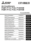
OCH576
1062
PUMY-P112VKM1(-BS)
PUMY-P125VKM1(-BS)
PUMY-P140VKM1(-BS)
*1 510
5
OUTLINES AND DIMENSIONS
Unit : mm