1
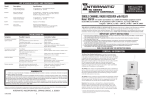
LIST OF AVAILABLE MODELS AND COMPONENTS
Model
Description
RC613L
Single Channel Receiver
with 36 in. Lead
RC613
Specifications
Single Channel Receiver
3-way switching module
RC613R
15 Amp Resistive, 10 Amp (1200 Watt) Tungsten,
1 HP Motor Load - 120 Volt
15 Amp Resistive, 10 AMp (1200 Watt) Tungsten,
1 HP - 120 Volt, Single Pole Single Throw Contacts.
Heavy-Duty Receiver
and Relay Assembly
RC615
30 Amp Resistive - 120/240 Volt, 12.5 Amp (1500 Watt)
Tungsten - 120 Volt, 1.5 HP - 120 Volt, 3 HP - 240 Volt
Double Pole Single Throw Contacts..
Single Channel Receiver
Timer Override Module
RC939
15 Amp Resistive, 10 Amp (1200 Watt) Tungsten
1 HP Motor Load - 120 Volt
3 Channel Transmitter
P1103ME
Operates on 9 Volt Battery
24 hr. Timer
Mechanism Only
20A. Resistive, 120-240V; 10A. Tungsten 120V;
1.5 HP-120V, 3HP-240V; 50/60 Hz; DPST
Note: Remove and discard leads between clock terminals
1 and 3 (jumper only) and 5 and relay. Connect BLUE leads from
Receiver to clock terminals 3 and 5. Connect RED lead from Receiver
to Relay coil. Connect BLACK and WHITE from Receiver to BLACK
and WHITE of Timer and to 120 volt supply. Connect 120V. load to
BLUE and WHITE, cap unused leads. For 240V. connections follow
instructions supplied with timer.
TROUBLESHOOTING
Symptom
No response to transmitter
signal at anytime
No response to transmitter
signal some of the time
Insufficient Range
Nuisance operation
Possible Cause(s)
Corrective Action
No power . . . . . . . . . . . . . . . . . . . . . . . . . . . . . . . . . . . . .Turn ON power at main panel
Loose connection(s) at receiver and/or load . . . . . . . . . .Check connections
Transmitter battery dead . . . . . . . . . . . . . . . . . . . . . . . . .Replace battery
Receiver and transmitter are on two different codes . . . .Change code settings (see page 3)
Faulty transmitter . . . . . . . . . . . . . . . . . . . . . . . . . . . . . . .Check battery connections, replace transmitter
Faulty receiver . . . . . . . . . . . . . . . . . . . . . . . . . . . . . . . . .Replace Receiver Module
Weak Battery . . . . . . . . . . . . . . . . . . . . . . . . . . . . . . . . . .Replace battery
Appliance with brush type motor is in use . . . . . . . . . . .Relocate appliance and/or connect to another circuit
Other radio transmitter (police, etc)
is operating nearby . . . . . . . . . . . . . . . . . . . . . . . . . . . . . .Change master code of transmitter (See page 3)
Receiver is at edge of range . . . . . . . . . . . . . . . . . . . . . . .Mount Receiver closer or higher
Weak battery . . . . . . . . . . . . . . . . . . . . . . . . . . . . . . . . . .Replace battery
Antenna too close to ground . . . . . . . . . . . . . . . . . . . . . .Relocate Receiver Module
Transmitter is held too close to ground . . . . . . . . . . . . . .Hold transmitter at least 3 ft. above ground
Weak signal due to obstruction . . . . . . . . . . . . . . . . . . . .Remote/relocate Receiver Module
Other radio transmitter (police, etc)
is operating nearby . . . . . . . . . . . . . . . . . . . . . . . . . . . . . .Change master code of transmitter (See page 3)
Fluctuating supply voltage due to surge, etc. . . . . . . . . .If frequent - install surge suppressor
Faulty receiver . . . . . . . . . . . . . . . . . . . . . . . . . . . . . . . . .Replace receiver module
LIMITED ONE YEAR WARRANTY
If within the warranty period specified, this product fails due to a defect in material or workmanship, Intermatic Incorporated will repair or replace
it, at its sole option, the unit free of charge. This warranty applies only to the original purchaser and is not transferable. This warranty does not apply
to: (a) damage caused by accident, abuse, mishandling, dropping, acts of God, or any negligent use; (b) units which have been subject to unauthorized repair, opened, taken apart, or otherwise modified; (c) units not used in accordance with instructions; (d) damages exceeding the cost of the
product. Some states do not allow a limitation of damages, so the foregoing limitation may not apply to you. This warranty gives you specific legal
rights and you may have other rights that vary from state to state.
INTERMATIC INCORPORATED WILL NOT BE LIABLE FOR INCIDENTAL OR CONSEQUENTIAL DAMAGES. THIS WARRANTY IS IN LIEU OF ALL OTHER
EXPRESS OR IMPLIED WARRANTIES. ALL IMPLIED WARRANTIES, INCLUDING THE WARRANTY OF MERCHANTABILITY AND THE WARRANTY OF
FITNESS FOR A PARTICULAR PURPOSE, ARE HEREBY MODIFIED TO EXIST ONLY AS CONTAINED IN THIS LIMITED WARRANTY, AND SHALL BE
OF THE SAME DURATION AS THE WARRANTY PERIOD STATED ABOVE.
This warranty service is available by either (a) returning the product to the dealer from whom the unit was purchased, or (b) mailing the product,
along with proof of purchase, postage prepaid to the authorized service center listed below. This warranty is made by: Intermatic Incorporated/After
Sales Service, 7777 Winn Rd., Spring Grove, IL 60081-9698/815-675-7000 http://www/intermatic.com Please be sure to wrap the product
securely when mailing to avoid shipping damage.
Because of our commitment to continuing research and improvements, Intermatic Incorporated reserves the right to make changes, without notice, in the specifications and material
contained herein and shall not be responsible for any damages, direct or consequential, caused by reliance on the material presented.
INTERMATIC INCORPORATED , SPRING GROVE, IL 60081-9698
http://www.intermatic.com
158RC12810
4
INSTALLATION
OPERATION &
SERVICE MANUAL
RC SERIES
REMOTE CONTROLS
SINGLE CHANNEL RADIO RECEIVERS
Model: RC613, RC613L Switching Module / Model: RC615 Timer Override Module
For indoor and outdoor use, suitable for Pool/Spa equipment control
ELECTRICAL RATING: 15 Amp Resistive, 1200 Watt Tungsten, 1 HP Motor Load - 120 Volt.
THIS DEVICE COMPLIES WITH FCC RULES PART 15. Operation of this device is subject to the following two conditions
1. This device may not cause harmful interference. 2. This device must accept any interference that may be received,
including interference that may cause undesired operation. FCC rules prohibit adjustments to or modification of receiver and
transmitter circuitry except for replacing the remote control battery. THERE ARE NO OTHER USER SERVICEABLE PARTS.
IMPORTANT SAFETY INSTRUCTIONS
1. This Control must be installed by a qualified electrician, according to National and Local Electrical Codes.
2. USE COPPER CONDUCTORS ONLY. If applicable, install this Control not less than 5 feet (3 meters for Canadian
installations) of inside edge of pool or spa.
3. Do not exceed the maximum ratings of individual components, wiring devices, and current carrying capacity of conductors.
4. For grounding of the installation, refer to section 250 and 680 of the National Electrical Code.
5. This Control should not operate any equipment which would cause bodily injury or property damage should it be
activated unexpectedly.
6. Always disconnect electricity at main panel before servicing this Control or the equipment(s) connected to it.
THIS CONTROL IS NOT TO BE USED AS A POWER DISCONNECT.
READ, FOLLOW AND SAVE THIS INSTRUCTION MANUAL
GENERAL INFORMATION
These Modular Radio Receivers are one half of a two part remote control system.
They operate as ordinary ON/OFF switches but they also respond to the signals of
a hand held transmitter - the other half of the system. The modules are designed for
indoor or outdoor use, and can handle a variety of switching applications, typical
around the house or farm. By the push of a button on the face of the transmitter, the
user is able to turn ON/OFF the connected load (lights, pump, etc.) from any remote
location*, safely and conveniently. In addition, a single transmitter can operate up to
four Receivers and is able to “teach” each Module a different code. (Transmitters are
sold separately).
Model RC613 Receiver Module comes with its own manual ON/OFF button and
it is intended to be installed at the location of the load. The connected load may be
turned ON/OFF using the hand-held transmitter or turned ON/OFF by pushing the red
button on the face of the Receiver.
Model RC613L Receiver Module is the same as RC613 except that it comes with
extra long (36 in.) leads.
Model RC615 Receiver Module is the same as the RC613L Module above, except
it has no manual ON/OFF button on its face. This Module is designed to be connected to a timer and will override its pre-set program, without affecting the next
automatic operation. At-site control of the load is possible by the ON/OFF switch of
the timer.
* The open field range is 200 feet but depends on many factors like the age of the battery, proximity of
large metal objects, the location of the receiver and environmental conditions at the time of transmission.
1
SPECIFICATIONS AND OTHER INFORMATION
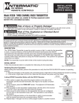
B. Timer Override Application
- use Model RC615
USEFUL INFORMATION
1. Radio Receivers are sensitive to heat. Avoid
mounting them above heater, air conditioner
or exposed to afternoon sun.
120V. TIMER
(T101B or SIMILAR)
An existing timer can only be upgraded if the
load connected to the timer is within the
capacity of the Receiver Module, see page 4.
Otherwise, the timer mechanism must be
replaced with Intermatic Model P1103ME, see
also note on page 4.
2. The higher the Receiver Module, the longer its
range. For good range and reliable reception, install
modules as high as practical above ground level with
antenna at top.
INDEPENDENTLY
WIRED
CLOCK MOTOR
1. Select the proper location (see Useful
Information on page 2) and install a radio
compatible timer on a vertical surface or
other support, using hardware, suitable for
the purpose.
2. Prepare the necessary conduit runs as required
by the installation layout and pull-in the
specified conductors.
3. Use one of the side knock-outs and a suitable
conduit-L, attach Model RC615 Receiver
Module to timer enclosure.
4. Follow wiring diagram B on the right,
make wire connections as shown.
5. Turn ON power, and test installation,
using the ON/OFF control of the timer.
6. Set code, see operating instructions on page 3.
3. Large metal objects divert radio signals. Avoid
mounting Receiver Modules on metal wall, fence
or near large metal objects.
4. Environmental conditions could effect the operation
of the remote control system. For example, in rain
the range may be less than normal.
5. Certain electric equipment like brush type motors
or electronic gas heater igniters emit radio signals
and can effect the function of the Receiver Module.
Avoid mounting modules near such equipment.
6. To prevent electronic interference, install Receiver
Modules at least 3 feet apart.
INSTALLATION
A. ON/OFF Switching Application
- use Model RC613 or RC613L
OPERATION
Make sure the intended load is within the capacity of the
Module, see ratings on page 1 and other choices on page 4.
In case this device is used to operate pool/spa equipment...
DANGER! To Reduce the Risk of Injury:
1. Attach Receiver Module to the top of an outdoor grade
junction box. Make sure the assembly is raintight.
... do not permit children to operate the Control Unit or use the Pool/Spa unless they are closely supervised at all times.
... test GROUND FAULT protection regularly. If it fails to reset, DO NOT USE THE POOL or SPA! Contact a qualified service technician.
A. To Set Code
2. Select the proper location (see Useful Information above) and
install Receiver assembly on a vertical surface or other support,
using hardware, suitable for the purpose.
Receiver Modules have the capacity to “learn”
and remember a unique code, generated by a
transmitter. The transmitter will operate only the
designated one or more receivers simultaneously.
In addition, each transmitter can “teach” and
operate up to three different sets of Receivers.
Also, more than one transmitter can be assigned
to operate the same Receivers.
3. Prepare the necessary conduit runs as required by the installation
layout and pull-in the specified conductors.
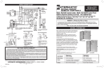
4. Follow wiring diagram A on the right, make wire connections
as shown.
5. If more than one Receiver Module is in use, repeat
above procedure on the next Receiver Module and
hold down the SAME transmitter button in step 2
if the Module is supposed to function TOGETHER
with the first or a DIFFERENT button if it is
supposed to operate INDEPENDENTLY.
1. Turn ON the main power and manually operate the
load a few times, then turn load OFF.
5. Turn ON power and test installation, using the ON/OFF button
on face of the Receiver Module. Replace junction box cover,
make sure the installation is secure and raintight.
To erase all memorized codes, press and hold
CODE SET button on Receiver Module, until the
green indicator light alongside goes out (in about 6
seconds).
2. Holding the Transmitter close to the Receiver
Module, press and hold the push button you
choose to operate that particular Module. The red
LED indicator should now be lit.
6. Set code, see Operating Instructions on page 3.
*Ground connections may or may not be as shown.
Diagram A
2
4. Code setting is now complete. Release the
transmitter button and test installation by pressing
repeatedly on the chosen transmitter button.
The load should cycle ON/OFF, if not, repeat
steps 2 and 3 above.
To operate a Receiver Module with more than one
transmitter, set master code switch, next to the
battery in transmitters to the same setting.
3. Press the “CODE SET” button on the face of the
Receiver Module until the green light next to the
button flashes ONCE (about one second).
3