1
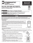
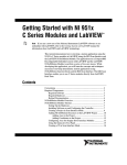
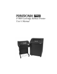
FIELD WIRING
INSTALLATION
OPERATION &
SERVICE MANUAL
P7000 SERIES
TIME CONTROLS
Model: P7000ME Series Electronic Time Control Mechanisms
IMPORTANT SAFETY INSTRUCTIONS
When installing and operating this Product and other associated equipment, basic safety precautions should always be followed,
including the following:
1. This Control must be installed by a qualified electrician, according to the National Electrical Code (Including Article 680) and
Local Electrical Codes.
2. USE COPPER CONDUCTORS ONLY. If applicable, install this Control not less than 5 feet from inside edge of pool or spa.
3. Do not exceed the maximum ratings of individual components, wiring devices, and current carrying capacity of conductors.
4. For grounding of the installation, refer to Article 250 and 680 of the National Electrical Code.
5. This Control should not operate any equipment which would cause bodily injury or property damage should it be activated unexpectedly.
6. Always disconnect electricity at main panel before servicing this Control or the equipment connected to it.
THIS CONTROL IS NOT TO BE USED AS A POWER DISCONNECT.
Note:
Ground
connections
are not shown.
READ, FOLLOW AND SAVE THIS INSTRUCTION MANUAL
GENERAL INFORMATION
WARRANTY
If within one (1) year from the date of installation, this product fails due to a defect in material or workmanship, Intermatic Incorporated
will repair or replace it free of charge.
The warranty does not cover labor for removal or reinstallation and does not apply to: (a) damage caused by accident, abuse, mishandling, or dropping; (b) a unit which has been subject to unauthorized repair; (c) units not used in accordance with directions; (d) damages
exceeding the cost of the product. Some states do not allow a limitation of damages so the foregoing warranty may not apply to you. This
warranty gives you specific legal rights and you may also have other rights which vary from state to state.
This warranty service is available, if the defective product or its defective component is returned with proof of purchase and date of
installation, either (a) to the dealer from whom the unit was purchased or (b) by shipping prepaid to the Intermatic Service Center, Intermatic
Incorporated, Intermatic Plaza, Spring Grove IL 60081-9698
These electronic modular timers are designed to
control electric appliances and equipment on a 7 day
schedule. They can turn ON and OFF the connected load
up to eight times daily and repeat the daily program 15
different ways. The timers are completely enclosed and,
when fully charged, the internal battery will hold up the
memory for at least 100 hours.
Model P7000ME series timer mechanisms are made
to fit any Intermatic indoor or outdoor, metal or plastic enclosure and service panels. They are intended to
replace older mechanical timers and also can be installed
in service panels as retrofits. These timers are compatible
with Intermatic’s RC series remote controls.
Model
Voltage
Contacts
Rating*HP
P7101ME
P7102ME
P7103ME
120
240
120/240
SPST
DPST
DPST
1
3
1.5/3
* All Models: 20A. Resistive - 120 or 240V. 10 A. Tungsten - 120V.
Because of our commitment to continuing research and improvements, Intermatic Incorporated reserves the right to make changes, without notice, in the specifications and material
contained herein and shall not be responsible for any damages, direct or consequential, caused by reliance on the material presented.
INTERMATIC INCORPORATED, SPRING GROVE, IL 60081-9698
http://www.intermatic.com
158T9898
4
1
SPECIFICATIONS
Timer:
Power Consumption:
Battery Reserve:
Minimum Interval:
# of Programming Periods:
Repeat Programs:
Microprocessor based 7-day clock
8VA
100 Hours minimum
1 Minute
8 ON / 8 OFF
M/T/W/Th/F/Sa/Su (different each day)
M+T+W+Th+F+Sa+Su (same every day)
M+T+W+Th+F (same on weekdays)
Sa+Su (same on weekends)
M+T+W+Th+F+Sa
M+W+F
T+Th+Sa
Th+F+Sa
INSTALLATION AND INTERNAL WIRING
Make sure the intended load is within the capacity
of the Timer, see ratings on page 1.
1.
Select the proper location (see Important Safety Instructions on
page 1) for the proper enclosure of your choice and install it on
a vertical surface or other support, using hardware suitable for
the purpose.
2. Prepare the necessary conduit runs as required by the installation
layout and pull-in the specified conductors.
3. Install timer mechanism in enclosure and follow wiring diagram
on page 4, make wire connections as shown.
4. Turn ON power and test installation, using the MANUAL button
on face of the Timer. Replace wiring compartment cover, make sure
the installation is secure and raintight.
5. Set Timer, see Operating Instructions on page 3.
SETTING / OPERATING INSTRUCTIONS
Programming Instructions
To Set or Change the Day and Time: To clear entire
memory, press
key. Hold down the CLOCK key
while pressing either the DAY, HOUR or MINUTE
keys. Continue pressing until the desired day or
number is shown. Then simply lift finger off the
CLOCK key to set.
To Set Program (ON/OFF times): Press TIMER key
once to enter into program mode. Display will show
“1 ON – – – –”. Press DAY key to choose any of 15
different day combinations for the first ON time.
Note: Days of the week having the same program
should be copied by selecting the desired combination
of days. Press the HOUR key and then the MINUTE key to
select the desired first ON time. Press TIMER key once.
Display will show “1 OFF – – – –”. Repeat previous
step to select the desired first OFF time. Repeat the
entire sequence to complete up to eight total ON/OFF
times as desired. When programming is done, press the
CLOCK key then the MANUAL key repeatedly until
the indicator bar is above the word “AUTO”.
To Review Program: Press TIMER key repeatedly.
When done, press CLOCK key to return to the time
of day.
To Cancel/Change Part of the Program: Press
TIMER key repeatedly until the particular ON or OFF
time appears, then repeatedly press the DAY key until
Display
Reset port
to cancel all
prior settings
ON/AUTO/OFF
Select Key
Indicator LED “ON”
when connected to
power source and
contacts are closed
Function Keys
the display shows “– – – –”. Set new ON or OFF time.
(See: To Set Programs)
To Override Automatic Operation: Press MANUAL
key to move indicator bar to the desired ON or OFF
position. Note: Timer will not resume automatic
operation until indicator bar is repositioned above
the word AUTO.
In case this device is used to operate pool/spa equipment...
DANGER! To Reduce the Risk of Injury:
... do not permit children to operate the Control Unit or use the Pool/Spa unless they are closely supervised at all times.
... test GROUND FAULT protection regularly. If it fails to reset, DO NOT USE THE POOL or SPA!
Contact a qualified service technician.
TROUBLESHOOTING
Symptom
Blank Display Possible Cause(s)
Corrective Action
Discharged battery . . . . . . . . . . . . . . . . Connect to power source
Defective timer . . . . . . . . . . . . . . . . . . . Replace timer
Timer will not respond
to programming
Memory is full . . . . . . . . . . . . . . . . . . . Press
to clear memory
Timer will not function
Timer is in MANUAL mode . . . . . . . . Press MANUAL key and move
as programmed
indicator bar over to AUTO
Timer is ON at all times
2
Timer is in ON mode . . . . . . . . . . . . . . See above
Defective timer . . . . . . . . . . . . . . . . . . . Replace timer
Defective relay . . . . . . . . . . . . . . . . . . . Replace relay
3