1
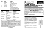
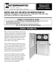
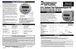
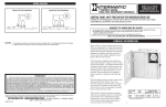
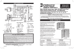
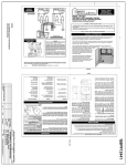
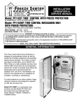
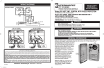
INSTALLATION
OPERATION &
SERVICE MANUAL
RC SERIES
REMOTE CONTROLS
Model: RC939 THREE CHANNEL RADIO TRANSMITTER
For indoor and outdoor use, suitable for Pool/Spa equipment control
BATTERY TYPE: 3 Volt CR2032 Coin Battery
WARNING Risk of Injury or Property Damage!
• Always keep remote controls out of reach of children. NEVER permit children to operate or play with remote controls.
• Never allow small children to play with batteries. If battery is swallowed, immediately notify doctor.
WARNING Risk of Fire, Explosion or Chemical Burn!
• Replace ONLY with 3 Volt CR2032 coin battery .
• DO NOT recharge, disassemble, heat above 212˚F (100˚C) or incinerate. NOTICE
To comply with FCC and or Industry Canada rules (IC), adjustment or modifications of this receiver and/or transmitter are prohibited,
except for changing the code setting or replacing the battery. THERE ARE NO OTHER USER SERVICEABLE PARTS.
Tested to comply with FCC Standards for Home or office use. Operation is subject to the following two conditions: (1) this device
may not cause harmful interference, and (2) this device must accept any interference received, including interference that may
cause undesired operation.
DESCRIPTION
The RC939 Radio Transmitter is used to control a pump or light. In order for the transmitter
to work, it must be linked to a RC613L/RC613R receiver that receives the ON/OFF
command from the transmitter and then turns the connected device (pump or light) ON/OFF.
This document provides setup and operation instructions for the RC939 radio transmitter.
Carefully follow these instructions to setup the RC939 transmitter. Then perform the operation
instructions as needed.
NOTE: The transmitter must be within 6 feet of the receiver during the setup.
INITIAL SETUP
Follow the procedures below to complete the initial setup for the transmitter.
Figure 1 RC939 Radio Transmitter
Verifying Receiver Operation
Before setting the transmitter, perform this procedure to verify that the RC613L/RC613R receiver is operating
properly.
1. Press the red button on the receiver. The connected pump or light will turn ON to indicate the receiver is working.
2. If the pump or light does not turn ON, make sure the receiver has power and then retest.
Linking RC939 Transmitter Button with the RC613 Receiver
Press one of
these buttons
to link to receiver
1) With a stylus or paper clip, press the program button on the side of the
transmitter until the red LED illuminates. See Figure 2 for location of button
and LED.
2) On the receiver, press the CODE-SET button. The adjacent LED illuminates.
See Figure 3.
3) Press a button on the transmitter multiple times until the LED on the receiver
turns OFF. This is the button that will control the receiver.
4) Press one of the other buttons on the transmitter that was not configured.
The red LED on the transmitter shuts OFF. The transmitter is now linked to
the receiver.
5) Press the configured button on the transmitter to verify it communicates
with the receiver and turns the connected device ON/OFF.
6) Repeat steps 1 through 5 to link an other program button to another receiver.
Program Button
Red LED
Figure 2 Side view of transmitter
Figure 3 RC613R Receiver
Linking Multiple transmitters with a Receiver
Up to three different transmitters can control a receiver. Follow steps 1 through 4 of Linking each RC939 transmitter
with the RC613 receiver.
OPERATION
The transmitter settings configured at Initial Setup can be adjusted as needed. Perform the applicable instructions
below to operate the transmitter and adjust a setting in the transmitter.
NOTE: The usable operation range for the transmitter is 100 Feet.
How to Use the Radio Transmitter
Once you setup the required links between the transmitter(s) and receiver(s), you are ready to use the transmitter.
Press the configured button on the transmitter to turn the connected device ON/OFF.
Excluding a Transmitter Button Link from a Receiver
Follow this procedure to exclude a transmitter button from a receiver:
1) With a stylus or paper clip, press the button on the side of the transmitter until the red LED illuminates.
NOTE: See Figure 2 for location of button and LED.
2) Press the configured ON/OFF button on the transmitter that you want to exclude from the receiver.
3) Press one of the other buttons on the transmitter. The red LED on the transmitter turns OFF.
4) Press the button you want to exclude to verify it does not control the receiver. The button is excluded.
Deleting All Codes from a Receiver
To delete all codes from a receiver, press and hold the Code-Set button until
the LED shuts off. All the codes are deleted from the receiver and all links
between the transmitter(s) and the receiver are deleted.
Changing the Transmitter Battery
Follow this procedure to remove or change the transmitter battery.
1.Insert a wide flat screwdriver into the slot on the side of the transmitter and
remove the cover.
2.Replace the CR2032 lithium coin type battery inside the transmitter.
NOTE: Make sure the new battery’s + terminal is facing away from
the circuit board on the transmitter.
3.Snap the cover onto the transmitter.
Figure 4
Figure 5 Removing transmitter cover
LIMITED ONE-YEAR WARRANTY
If
within the warranty period specified, this product fails due to a defect in material or workmanship, Intermatic Incorporated will repair or replace it, at its sole option, free of charge. This warranty is extended to the original household purchaser only and is not transferable. This warranty does not apply to: (a) damage to units caused by accident, dropping or abuse in handling, acts
of God or any negligent use; (b) units which have been subject to unauthorized repair, opened, taken apart or otherwise modified; (c) units not used in accordance with instructions; (d) damages
exceeding the cost of the product; (e) sealed lamps and/or lamp bulbs, LED’s and batteries; (f) the finish on any portion of the product,such as surface and/or weathering, as this is considered
normal wear and tear; (g) transit damage, initial installation costs, removal costs, or reinstallation costs.
INTERMATIC INCORPORATED WILL NOT BE LIABLE FOR INCIDENTAL OR CONSEQUENTIAL DAMAGES. SOME STATES DO NOT ALLOW THE EXCLUSION OR LIMITATION OF INCIDENTAL OR CONSEQUENTIAL DAMAGES, SO THE ABOVE LIMITATION OR EXCLUSION MAY NOT APPLY TO YOU. THIS WARRANTY IS IN LIEU OF ALL OTHER EXPRESS OR IMPLIED WARRANTIES. ALL IMPLIED WARRANTIES, INCLUDING THE WARRANTY OF MERCHANTABILITY AND THE WARRANTY OF FITNESS FOR A PARTICULAR PURPOSE, ARE HEREBY MODIFIED TO EXIST ONLY AS CONTAINED IN THIS LIMITED WARRANTY,
AND SHALL BE OF THE SAME DURATION AS THE WARRANTY PERIOD STATED ABOVE. SOME STATES DO NOT ALLOW LIMITATIONS ON THE DURATION OF AN IMPLIED WARRANTY, SO THE ABOVE
LIMITATION MAY NOT APPLY TO YOU.
This warranty service is available by either (a) returning the product to the dealer from whom the unit was purchased or (b) completing a warranty claim online at www.intermatic.com.
This warranty is made by: Intermatic Incorporated, Customer Service 7777 Winn Rd., Spring Grove, Illinois 60081-9698. For warranty service go to: http://www.Intermatic.com or call
815-675-7000.
INTERMATIC INCORPORATED,
Spring Grove, Illinois 60081-9698
www.intermatic.com
158--01244-REVB