1
REV.-~
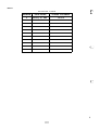
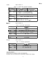
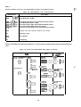
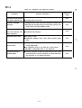
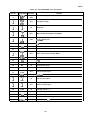
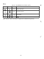
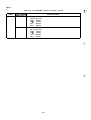
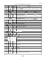
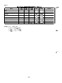
Table A-9. GA E05A16GA Port Functions
Function
Pin No. Signal Name Direction
1
J
DB4
J
4
DB7
5
RXDIN
IN
RXD signal input port
6
RSTIN 1
IN
Reset signal input No. 1 RSTIN 1 signal is output to RSTOUT signal port.
7
15
I
I
IN/OUT
Vss
Ground
–
I
Multiplex tri-state data bus bit 4-7 The data is output when RD signal is low.
RSTIN
IN7
IN
Reset signal input No.2 RSTIN 2 signal is output to RSTOUT signal port.
J
IN2
IN
Parallel data input port
The data from the host computer is latched when the strobe signal is input.
I
STRB
IN
Strobe signal input port
The parallel data from host computer is latched by STRB signal.
IN
Parallel data input port.
The data from the host computer is latched when the strobe signal is input.
17
IN 1
18
I NO
19
RSTOUT
OUT
Reset signal output port
20
BUSY
OUT
Busy signal output port
21 I ACK I OUT I
Acknowledge
signal
output
port
22
PE
OUT
Paper end signal output port
23
ERR
OUT
Error signal output port
PC3
OUT
output port
J
Pco
2 8 I R X D O U T I O U T ISerial dataoutput
29
30
31
33
34
35
PD1
PDO
] PAO I
IN
OUT
I
input
+----L
port
output port
port
Input port
PC4
J
PC7
out
output port
OUT
output port
PBO
~
PB7
ss
48
‘
49
PA3
J
53
J
PA7
I
-
Ground
IN
Input port
IN
Address input port (low address bit O-2)
AO
J
A2