1
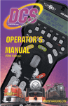
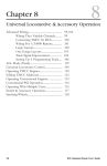
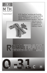
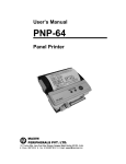
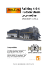
by mth electric trains
ACCESSORY INTERFACE UNIT
OPERATOR’S MANUAL
Compatibility
This device is compatible with any model railroading accessory or switch
activated by an external power supply or control switch. Consult the
individual item’s operator’s manual for specific instructions on how to
operate the accessory or switch.
PLEASE READ BEFORE USE AND SAVE
Table of Contents
Introduction To The AIU.................................................................................... 3
Required Tools...................................................................................... 3
Installing The AIU Into The DCS System.........................................................4
Wiring To The TIU................................................................................4
Daisy Chaining AIUs Together............................................................. 4
Programming AIUs Into The DCS System....................................................... 5
Wiring Accessories And Switches...................................................................... 6
Operating Track Section....................................................................... 6
Switches And Turnouts..........................................................................7
Accessories With Two Contacts........................................................... 8
Accessories With Three Contacts......................................................... 9
Accessories With Four Contacts........................................................... 10
Accessories With Five Contacts............................................................ 11
Programming Individual Accessories And Switches Into The DCS System 12
Programming Accessories..................................................................... 12
Programming Switches.......................................................................... 15
Activating Accessories And Switches .................................................................17
Troubleshooting AIU Problems..........................................................................19
Service & Warranty Information.......................................................................20
Limited One-Year Warranty..................................................................20
CAUTION: ELECTRICALLY OPERATED PRODUCT:
Not recommended for children under 10 years of age. M.T.H. recommends adult supervision with child ren ages 10 - 16.
As with all electric products, precautions should be observed during handling and use to reduce the risk of electric shock.
WARNING:When using electrical products, basic safety precautions should be observed, including the following:
Read this manual thoroughly before using this device.
l
M.T.H. recommends that all users and persons supervising use examine the hobby transformer and other electronic equipment
periodically for conditions that may result in the risk of fire, electric shock, or injury to persons, such as damage to the primary
cord, plug blades, housing, output jacks or other parts. In the event such conditions exist, the train set should not be used until
properly repaired.
l
Do not operate your layout unattended. Obstructed accessories or stalled trains may overheat, resulting in damage to your layout.
l
This train set is intended for indoor use. Do not use if water is present. Serious injury or fata lity may result.
l
Do not operate the hobby transformer with damaged cord, plug, switches, buttons or case.
Introduction To The AIU
The Accessory Interface Unit (AIU) turns the DCS System into a complete
layout control system. Each AIU controls up to 10 accessories and 10 switches
(turnouts) and allows you to control routes and scenes through your remote
control.
The AIU itself is essentially a box of relays that is especially designed to receive signals
from the DCS System. The remote tells the AIU which relay to trigger, and it sets the
accessory or switch into motion.
TIU
Connection
Port
AIU
Connection
Port
Accessory/Switch
Connection Banks
Digital
Input
(For Future Use)
Required Tools
ACC
IN = Armature of Relay
1 = NO (normally open)
2 = NC (normally closed)
SW
IN = AC Common
1 = Straight
2 = Curved
A flathead jeweler’s screwdriver for wiring into the AIU
DCS Accessory Interface Unit
3
Installing The AIU Into
The DCS System
Once you have completed the wiring and set up instructions below, it is easy to activate
accessories and throw switches using only the thumbwheel and a single softkey. Be
careful to wire each accessory as its instructions dictate, and you will have your system
working in no time.
Wiring To TIU
Plug one end of the AIU/TIU cable (included) into the “TIU Input” port on the AIU and
the other end into the “AIU Input” port of the TIU.
Daisy Chaining AIUs Together
Plug one end of the AIU/TIU cable (included with second AIU) into the “AIU
Output” port of the first AIU (connected to the TIU) and the other end into the
“TIU Input” port of the
second AIU.
Note: You can daisy chain
up to five AIUs for each
TIU on your layout.
4
DCS Accessory Interface Unit
Programming AIUs Into The
DCS System
Before you can add accessories and switches for activation by DCS, you must
first read all connected AIUs into the system.
With all TIUs and AIUs properly wired and the transformer set to 18v, press
READ on the DCS handheld. The system will automatically locate and add new
AIUs to its map.
See the DCS System Operating Instructions for complete instructions on adding and
numbering the TIUs on your system.
INACTIVE ENG
INA S/U ALL
FOUND TIU ADDRESs 1
WITH 1 AIU BOXES
CONNECTED
READ
DCS Accessory Interface Unit
5
Wiring Accessories and
Switches - Revised Diagram
You can wire up to 10 accessories plus 10 switches into each AIU.
Because accessories come in so many different configurations, you should carefully
check the wiring instructions for each specific accessory before connecting to the
AIU. Below are general guidelines to help you complete this wiring.
Operating Track Sections
6
(Wired For Track Power)
DCS Accessory Interface Unit
Switches/Turnouts
AC Ground
Curved
Straight
DCS Accessory Interface Unit
7
Accessories With Two Contacts
Examples Include:
Lighted Row House
Operating Radar Tower
Operating Rotary Beacon
8
DCS Accessory Interface Unit
Accessories With Three Contacts
Examples Include:
Operating Semaphore
Operating Block Signal
Note: Accessories
controlled by a track
activation device
(TAD) or infrared
track activation
device (ITAD) can be
wired up to the AIU
as well as the TAD or
ITAD. Such a
configuration will
allow the accessory
to be triggered
remotely by the AIU
and DCS remote or
via a train on the
track when passing
by the TAD or ITAD.
Wire the accessory to
the AIU as described
on the preceding and
following pages.
DCS Accessory Interface Unit
9
Accessories With Four Contacts
Examples Include:
Operating Passenger
Platform
D C B A
Note: To control
lights and operation
separately, you can
wire the lights into
one ACC port and the
operation wires into
another.
D
C
B
10
A
DCS Accessory Interface Unit
Accessories With Five Contacts
Examples Include:
Operating Car Wash
Operating Gas Station
Operating Firehouse
AB CD E
A
B
C
D
E
DCS Accessory Interface Unit
11
Programming Individual
Accessories & Switches Into
The DCS System
Programming Accessories
Turn off the power supply, then make sure the accessory has been wired into the
AIU as shown in the preceding examples and according to your accessory’s
instructions.
Power up to 18 volts and press READ on the DCS handheld to add your AIU to
the DCS system (see page 5 for more explanation). Go through the DCS
handheld’s menu as follows:
Scroll And Select
1. Press the Black MENU button to bring up the four main System
menus in the DCS system.
2. Using the thumbwheel,
scroll down the menu list
until you arrive at System.
Press Menu
SOUND
CONTROL
SYSTEM
ADVANCED
3. Press the thumbwheel
to enter the System Menu.
Your screen should reveal
at the bottom that you are
in the System Menu.
4. Scroll and select
Accessory Setup from the
available choices in the
System Menu.
5. Scroll and select Add
Accessory from the
available choices in the
Accessory Setup Menu.
MENU
12
SOUND
CONTROL
SYSTEM
ADVANCED
Scroll Amd Select
Accessory Setup
SWITCH SETUP
ACCESSORY SETUP
SET REMOTE ADDRESS
MENU: SYSTEM
Select Add Accessory
ADD ACCESSORY
EDIT ACCESSORY
DELETE ACCESSORY
MENU: ACCESSORY SETUP
DCS Accessory Interface Unit
Programming Accessories (cont’d)
6. Select which TIU
the accessory is
wired to (via the
AIU) (See the TIU
Setup section in the
DCS User’s Manual
for how to number
TIUs.)
AIU
#1
AIU
#2
AIU
#3
7. Select which
AIU the accessory is
added to. To
determine the AIU’s
number, simply
count out from the TIU. For instance, if you
have three AIUs, the one connected directly to
the TIU is AIU1, the one connected directly to
AIU1 is AIU2, and the one connected directly to
AIU2 is AIU3.
8. Select the AIU port (ACC1-ACC10) the
accessory is wired into.
AIU
#4
AIU
#5
Select TIU To Use
1
2
3
SEL TIU TO USE
Select AIU To Use
1
2
3
SEL AIU TO USE
Select Accessory #
ACC !
ACC 2
ACC 3
SEL ACCESSORY #
Select Characters For
Accessory Name
(Highlighted By Brackets)
[A]BCDEFGHIJKLMNO
PQRSTUVWXYZ#- &
O123456789<D
ENTER ACCESS NAME
DCS Accessory Interface Unit
13
Programming Accessories (cont’d)
10. You may give the accessory a name up to 16
characters long. Select the “D” at the end of the
character set to signify that you are done with
this function.
11. The accessory will now show up, by the
name you have assigned, on the accessory screen
when you press the DCS handheld’s ACC button.
See the DCS System Operating Instructions
for complete instructions on editing and renaming
accessories and for instructions on adding and
numbering TIUs.
Select Characters For
Accessory Name
[A]B[C]DEFGHIJKLMNO
PQRSTUVWXYZ#- &
O123456789<D
car w
Select the “D”
Character To Enter
Name For Accessory
ABCDEFGHIJKLMNO
PQRSTUVWXYZ#- &
O123456789<[D]
car wash
Accessory Name As
Seen In Accessory
List
!:
2:
3:
ALL
14
DCS Accessory Interface Unit
car wash
Gas Station
Firehouse
S/U ON OFF ACT
Programming Switches
Turn off the power supply, then make sure the switch has been wired into the
AIU as shown in the preceding examples and according to your switch’s
instructions.
Power up to 18 volts and press READ on the DCS handheld to add your AIU to
the DCS system (see page 5 for more explanation). Go through the DCS
handheld’s menu as follows:
1. Wire the switch into the AIU as shown in the AIU
Scroll And Select
user’s manual and your track’s instructions.
System
2. Go through the DCS handheld’s menu as follows:
A. Press Menu Button
Press Menu
SOUND
CONTROL
SYSTEM
ADVANCED
B. Select System
SOUND
CONTROL
SYSTEM
ADVANCED
Scroll Amd Select
Switch Setup
C. Select Switch
Setup
D. Select Add Switch
SWITCH SETUP
ACCESSORY SETUP
SET REMOTE ADDRESS
MENU: SYSTEM
Select Add Switch
MENU
ADD SWITCH
EDIT SWITCH
DELETE SWITCH
MENU: SWITCH SETUP
Select TIU To Use
3. Select which TIU the switch is wired to (via the
AIU).
DCS Accessory Interface Unit
1
2
3
SEL TIU TO USE
15
Programming Switches (cont’d)
4. Select which AIU the switch is added to. (See
the explanation for counting AIUs in the
Programming Accessories section on page 13.)
5. Select the AIU port (SW1-SW10) the switch is
wired into.
Select AIU To Use
1
2
3
SEL AIU TO USE
Select Switch #
SW !
SW 2
SW 3
SEL SWITCH #
Select Characters For
Accessory Name
4. The LCD prompts you to name the switch,
and an alphanumeric character set is displayed.
Use the thumbwheel to scroll through the
character set, and when the character you want to
type next is bracketed, press the thumbwheel to
select it. You may give the switch a name up to
16 characters long. Select the “D” at the end of
the character set to signify that you are done with
this function (See page 13 - 14 for more
informationon naming accessories) .
The switch will now show up, by the name you have
assigned, on the switch screen when you press the
DCS handheld’s SW button.
See the DCS System Operating Instructions for complete
instructions on editing and renaming switches and for
instructions on adding and numbering TIUs.
16
(Highlighted By Brackets)
[A]BCDEFGHIJKLMNO
PQRSTUVWXYZ#- &
O123456789<D
ENTER ACCESS NAME
Switch Name As Seen
In Accessory List
!:
2:
3:
ALL
DCS Accessory Interface Unit
siding switch 1
siding switch 2
yard switch 1
S/U
Activating Accessories and
Switches
Once you have completed the wiring, mapping, and naming steps, you can easily
activate an accessory or switch.
1. Press the handheld’s ACC (for accessory control) or SW (for switch
control) button.
2. Scroll the thumbwheel until the arrow points to the accessory or switch
you want to activate.
3. Press the softkey under the option you choose (see below for options).
Press ACC or SW
!: ABC
2: Gas Station
3: Firehouse
ALL S/U ON
ACC
or
SW
Scroll To Select
OFF
ACT
!:
2:
3:
ALL
car wash
Gas Station
Firehouse
S/U ON OFF ACT
Press Softkey Option
ON
ACCESSORY
1: car wash
For accessories the softkey
options are ALL, S/U, ON, OFF,
ACT. ALL triggers all
accessories connected to any TIU
and receiving track power. S/U
takes you to the handheld’s setup menu, where you can add, edit, or delete an
accessory. ON turns accessories on for continuous operation until you turn them
off. OFF turns accessories off. ACT activates accessories for single, not
continuous, operation.
DCS Accessory Interface Unit
17
Activating Accessories & Switches (cont’d)
For switches the softkey options are ALL, S/U, ñ or ö ALL triggers all
switches connected to any TIU and receiving track power to move into the
position you select. S/U takes you to the handheld’s
setup menu, where you can add, edit, or delete a
switch. ñ throws the switch straight. ö throws the
!: siding switch 1
2: siding switch 2
switch curved.
3: yard switch 1
ALL
S/U
Note: Unlike with engines, the ALL button for accessories
and switches does not distinguish between active and
inactive. The button activates every accessory or switch that is connected to a TIU and
receiving track power
18
DCS Accessory Interface Unit
Troubleshooting DCS AIU Problems
Although DCS has been designed and engineered for ease of use, you may have some
questions during initial operation. The following table should answer most questions. If
your problem cannot be resolved with this table, visit the MTH Proto-Sound web site for
more information and instructions for contacting MTH for direct service.
www.protosound2.com
Accessory/Switch Doesn't Activate
Remedy
When I activate the accessory/switch from Check to make sure the accessory/switch
the handheld, nothing happens, or the
is mapped correctly in the handheld. The
wrong accessory/switch activates.
DCS system knows only to activate
whatever is wired into the AIU and port
you map, so a mis-mapped model will not
activate.
AIUs Don't Respond
Remedy
I have multiple AIUs daisy chained
Make sure you are using the AIU/TIU
together, but the accessories on the last
cables included with the AIUs. While
AIUs in the chain do not activate properly. other cables may look similar, they may
cause voltage drop and drain off too much
power for the signal to reach the outer
AIUs.
Switch Sticks
Remedy
The switch opens but won't close.
There is no reason the AIU should
Remedy
cause this. Check your switch and
wiring for defects. (See Page 7)
DCS Accessory Interface Unit
19
Service & Warranty Information
How to Get Service Under the Terms of the Limited One-Year Warranty
For warranty repair, follow the instructions below to obtain warranty service.
First, e-mail, write or fax M.T.H. Electric Trains to obtain Repair Authorization. You can find the
contact information for M.T.H. by visiting www.protosound2.com/service/. Once there fill out the
service request form and submit it via the web site. After contacting M.T.H., you will receive via
email or phone a return authorization number and directions on where to ship the defective DCS
component.
CAUTION: Make sure the product is packed in its original factory packaging including its foam and
plastic wrapping material so as to prevent damage to the merchandise. The shipment must be prepaid
and we recommend that it be insured. A cover letter including your name, address, daytime phone
number, e-mail address (if available), Return Authorization number, a copy of your sales receipt
and a full description of the problem must be included to facilitate the repairs. Please include the
description regardless of whether you discussed the problem with a service technician when
contacting M.T.H. for your Return Authorization.
Please make sure you have followed the instructions carefully before returning any merchandise for
service.
Limited One-Year Warranty
All M.T.H. products purchased from an Authorized M.T.H. Train Merchant are covered by this
warranty.
See our website at www.mth-railking.com or call 1-888-640-3700 to identify an Authorized M.T.H.
Train Merchant near you.
M.T.H. products are warrantied for one year from the date of purchase against defects in material or
workmanship, excluding wear items such as light bulbs, pick-up rollers, batteries, smoke unit wicks,
and traction tires. We will repair or replace (at our option) the defective part without charge for the
parts or labor, if the item is returned to M.T.H. Electric Trains within one year of the original date of
purchase. This warranty does not cover damages caused by improper care, handling, or use.
Transportation costs incurred by the customer are not covered under this warranty.
Items sent for repair must be accompanied by a return authorization number, a description of the
problem, and a copy of the original sales receipt from an Authorized M.T.H. Train Merchant ,
which gives the date of purchase. If you are sending the item to M.T.H., fill out the Service Contact
form in the Service Section of www.mth-railking.com; send US mail to the address listed below; call
410-381-2580, or fax 410-423-0009 to obtain a return authorization number. If you are sending this
product to an Authorized Service Center, contact that Center for their return authorization.
This warranty gives you specific legal rights, and you ma y have other rights that vary from state to
state.
Service Department
M.T.H. Electric Trains
7020 Columbia Gateway Drive
Columbia MD 21046-1532