1
OPERATING AND SERVICE MANUAL
80058
PULSE GENERATOR
SERIAL NUMBERS
This manual applies directly to instrument serial number
1627G00731.
With changes described in Section IX, this manual also
applies to all earlier instruments.
For additional important information about serial numbers,
see INSTRUMENTS COVERED BY MANUAL in Section I.
© HEWLETT-PACKARD GmbH
1973
Herrenbergerstr 110, D-703 B6blingen,
Federal Republic of Germany
MANUAL PART NO. 08005-90004
Microfiche Part No. 08005-90504
Printed: MAY 1977
General Information
Modei8005B
Figure 1-1.80058 Instrument and Accessories.
Figure 1-2, Rack-mount Kit, Option 908
1-0
Model80058
General Information
SECTION I
GENERAL INFORMATION
1-1
INTRODUCTION
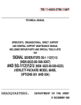
1-2 This Operating and Service Manual contains information required to install, operate, test, adjust and
service the Hewlett-Packard Model 80058. Figure 1-1
shows the instrument and accessories supplied. This section covers instrument identification, description, accessories, specifications, and other basic information.
rate as possible, Hewlett-Packard recommends that you
periodically request the latest ManUal Change supplement.
The supplement for this manual is identified with this
manual's print date and part number, both of which
appear on this manual's title page. Complimentary copies
of the supplement are available from Hewlett-Packard.
HEWLETT- PACKARD
1-3 A microfiche version of this manual is available
on 4 x 6 inch microfilm transparencies (order number on
title page}. Each microfilm contains up to 60 photo·
duplicates of the manual pages. The microfiche package
also includes the latest Manual Changes supplements as
well as all pertinent Service Notes.
GmbH
I1536G 00062
I
B(J'Bll NGEN ..
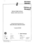
Figure 1-3. Serial Number Plate
1-11 DESCRIPTION
1-4 SPECIFICATIONS
1-5 Instrument specifications are listed in Table 1-2.
These specifications are the performance standards or
limits against which the instrument is tested.
1-12 The Model 80058 is a versatile 20 MHz pulse
generator that can deliver up to 10 volts positive and,
simultaneously, 10 volts negatiVe into a 50 ohm load from
a selectable source impedance. Provision is made for external and manual triggering, synchronous and asynchro-
1-6 SAFETYCONSIDERATIONS
1-7 The Model80058 is a Safety Class 1 instrument
(it has an exposed metal chassis that is directly connected
to earth via the power supply cable}.
1-8 This operating and service manual contains information, cautions, and warnings which must be followed
by the user to ensure safe operation and to maintain the
instrument in a safe condition.
nous gating, a positive trigger output and TTL output of
4.6 volts across an open circuit for positive or negative
logic.
1-13 Repetition rate is variable over the range 0.3 Hz
to 20 MHz, alternatively, in double pulse mode 10 MHz
simulating 20 MHz or, in square wave mode, 0.15 Hz to
10 MHz. Pulse delay (with respect to the trigger output}
is variable over the range< 100 ns to 3 s. Pulse width is
variable over the range 25 ns to 3 s with a normal mode
duty cycles of> 80% and 100% in complement mode.
Transition times (pulse rise and fall) are variable from
10 ns to 2 s with a rise and fall lor fall to rise} ratio of
up to 30:1. Amplitude and base line offset of each
channel is independently variable. A complete set of
specifications is given in Table 1-2.
<
1-9 INSTRUMENTS COVERED BY MANUAL
1--10 Attached to the rear of this instrument is a serial
number plate (Figure 1-3}. The first four digits of the
serial number only change when there is a significant
change to the instrument. The last five digits are assigned
to instruments sequentially. The contents of this manual
apply directly to the instrument serial number quoted on
the title page. For instruments with lower serial numbers,
refer to the backdating information in Section IX of this
manual. For instruments with higher serial numbers, refer
to the Manual Change sheets at the end of this manual.
In addition to change information, the Manual Change
sheets may contain information for correcting errors in
the manual. To keep this manual as up-to-date and accu-
1-14 OPTIONS
1-15 The following options are available:
Option 908
Rack-mount kit
Option 910
Additional Copy of the Operating
and Service Manual.
These options will be shipped with the instrument if
ordered at the same time.
1-1
Genera! Information
Modei8005B
1-18 RECOMMENDED TEST EQUIPMENT
1-16 ACCESSORIES SUPPLIED
1~ 17 The instrument is supplied complete with the
following items (see Figure 1~1).
ITEM
HP PART NUMBER
800 mA Fuse for 230V operation
2110-0020
1.6 A Fuse for 115V operation
Power cable
Operating and Service Manual
2110-0005
see Figure 2~ 1
08005-90004
1-19 Equipment required to maintain the modei8005B
is listed in Table 1-1. Other equipment can be substituted
if it meets or exceeds the critical specifications listed in
the table.
Table 1-1 Recommended Test Equipment
INSTRUMENT TYPE
RECOMMENDED MODEL
REQUIRED
CHARACTERISTICS
Oscilloscope
HP 180C with plug-ins
1805A and 1825C
Dual Channel, 50 MHz band
width, 5 mV/div. sensitivity
sweep speeds 5ns/div. to 2s/
div. with sweep delay
PA
Sampling
Oscilloscope
HP 180C with plug-in 1810A
Dual Channel, 1 GHz bandwidth, 1 mV/div. sensitivity
sweep speeds 10ns/div. to
2s/div.
PA
Square Wave
Generator
80138
Capable of rep. rate of 10kHz,
10kHz, negative output 10
to -5V), fast rise and fall
times (5ns)
p
Digital Voltmeter
34740A
with 34702A
100V range to 4 significant
figures. Accuracy± 0.05% ±
1 digit
A
AC Voltmeter
HP 3400A
Sensitivity 1OO!iV to 300V
rms
A
Test Oscillator
HP 651 B
Frequency Range 10Hz to
10 MHz
p
Couater
HP 5345A
0-50 MHz
PA
50!1 cable assembly
HP 10503A
(4 required) terminated each
end with BNC male connectors
PA
50Q Tee connector
1250-0781
PA
50!1 Feed-through
termination (2)
HP 10100C
PA
Attenuator
HP 8491A
20 dB 50 !1, N
PA
Connector
HP 1250-0077
BNC male toN female
PA
Connector
HP 1250-0780
BNC male toN male
PA
NOTE: P =Performance Check
A = Adjustment
1-2
REQUIRED FOR
General Information
Model 80058
Table 1-2 Specifications
Maximum output: (amplitude + offset) 1OV.
PULSE CHARACTERISTICS
lnwna!
son
IN
IN
OUT
IN
IN
OUT
...
,
Ext.
Amplitude
Range Selected
Output(+)
son
125V/25V
300mV to 1.25V
H•gh Z
1 25V/2.5V
1.25V/2.5V
600mV to 2 5V
son
son
High Z
son
5V/10V
5V/10V
5V/10V
""'"'
Amplitude
600mV to 2.0V
125Vto5V
2.5V 10 10V1
2.5V to JOV 1
'
'
'
'
'
'
2V
'V
' 2V
'
'' 2V2V
' 2V
'V
'V
to
OV -4V 2
t
t<J
OV +4V 1
1. The maximum output (amplitude+ offset) is 10V.
2. Offset range with amplitude vernier CCW is
Output protection: cannot be damaged by short circuit
or application of external voltages,;;;± 10V (at 25°C
ambient) independent of control settings.
'V
2V
2V
2V
OutpUt{-)
± 2V. Offset
range increases to ±4V when amplitude vernier is CW.
Transition times:~ 10ns to 2s in six ranges. Separate
verniers provide independent control of leading and
trailing edges within each range. Ranges are common
for leading and trailing edges. Max. leading edge/trailing
edge ratio, 1:30 or 30:1.
Source impedance: 50 ohms ± 10% (shunted by typ
20pF) or high impedance, switch selectable.
TTL compatible output: fixed amplitude, +4.6V across
open circuit.
Source impedance: 50 ohms typ.
Pulse formats: normal or complement, switch selectable.
REPETITION RATE AND TRIGGER
Repetition rate: 0.3 Hz to 20 MHz in five ranges. Ver~
nier provides continuous adjustment within each range.
Linearity: for transition times > 30ns, maximum ampli~
tude deviation from a straight line between the 10% and
90% points is less than 4% of pulse amplitude.
Period jitter;
Overshoot, preshoot and ringing: each less than 5% of
pulse amplitude.
Trigger output: positive pulses > 2V amplitude across
external 50 ohm load.
Pulse width: < 25ns to 3s in five ranges. Vernier provides continuous adjustment within each range.
Output Trigger pulse width: 15ns ± 7ns.
Width jitter:< 0.1% +50 ps of any width setting.
EXTERNALLY CONTROLLED OPERATION
Maximum duty cycle:> 80% for repetition rates from
0.3 Hz to 1 MHz, >50% from 1 MHz to 20 MHz. Up
to 100% when using pulse complement.
External Triggering
Square wave: 0.15 Hz to 10 MHz. Duty cycle: 50%±
5% for repetition rates< 1 MHz, increasing to 50%±
15% at 10 MHz.
Delay: approximately 35ns between trigger input and
trigger output.
Pulse delay: < 100ns to 3s (with respect to trigger output) in five ranges. Vernier provides continuous adjust~
ment within each range. Delay is inhibited in Square Wave
mode.
< 0.1%
of any period setting.
Double pulse: 10 MHz max. Simulates 20 MHz.
Repetition rate: de to 20 MHz.
Manual: push button for generating single pulse (two in
double pulse).
Trigger Input
Delay jitter:< 0.1% +50 ps of any delay setting.
Pulse outputs: simultaneous positive, negative and TTL
compatible outputs.
Maximum pulse amplitude: 5V, with internal 50 ohms
and external 50 ohms. 1 OV with internal 50 ohms and
external high impedance, or with internal high impeM
dance and external 50 ohms.
Input impedance: approx. 1 kohm, de coupled
Maximum input:
± 1OV.
Sensitivity: sine waves; 2Vpp. Pulses 1 V peak.
Polarity: positive or negative, switch selectable.
Minimum pulse width: 1 Ons.
1-3
General Information
Mode/80058
Table 1-2 Specifications (continued)
Gating
Synchronous: gate signal turns on repetition rate. Time
Gate signal polarity: negative.
Gate amplitude: 2V to 20V (max.)
between start of gate and first pulse defined by delay
control. Last pulse is always completed even if gate ends
during generation of last pulse. Synchronous trigger
pulses occur for duration of gate.
GENERAL
Operating temperature range: 0°C to 55°C.
Power: 115V or 230V, +10%, -15%,48 Hz to 440Hz,
Asynchronous: gate signal controls output of free running repetition rate generator.
180VA max.
Weight: net 7 kg (16 lbs), shipping 9 kg (20 lbs).
Gate Input
Input impedance: approx. 1 kohm, de coupled.
1-4
Dimensions: 425 mm wide, 140 mm high, 336 mm deep
(16 3/4 in. x 5 1/2 in. x 13 1/4 in.).
Installation
Modei8005B
SECTION II
INSTALLATION
2-1
INTRODUCTION
2-2
This section provides installation instructions for
2-10 Power Cable
the Model 8005B Pulse Generator and its accessories. It
also includes information about initial inspection and
damage claims, preparation for use, and packaging, storage and shipment.
To avoid the possibility of injury or death, the following
precautions must be followed before the instrument is
switched on:
2-3 INITIAL INSPECTION
2-4
Inspect the shipping container for damage. If the
container or cushioning material is damaged, it should be
kept until the contents of the shipment have been checked
for completeness and the instrument has been checked
mechanically and electrically, The contents of the ship·
ment should be as shown in Figure 1-1 plus any accessories that were ordered with the instrument. Procedures
for checking the electrical operation are given in Section
3. If the contents are incomplete, if there is mechanical
damage or defect, or if the instrument does not pass the
operator's checks, notify the nearest Hewlett-Packard
Sales/Service office. If the shipping container is damaged,
or the cushioning material shows signs of stress, notify
the carrier as well as the Hewlett-Packard office. Keep the
shipping materials for carrier's inspection. The HP office
will arrange for repair or replacement without waiting for
settlement.
a. If this instrument is to be energized via an autotransformer for voltage reduction, m'ake sure that
ground connection is not interrupted.
b. The power cable plug shall only be inserted into a
socket outlet provided with a protective ground contact. The protective action must not be negated by the
use of an extension cord without a protective conduc·
tor.
c. Before switching on the instrument, the protective
ground terminal of the instrument must be connected
to a protective conductor of the power cable. This is
verified by checking that the resistance between the
instrument chassis and the front panels of all modules
in the instrument and the ground pin of the power
cable plug is zero ohms.
2-5 PREPARATION FOR USE
2-6 Power Requirements
2-7
The 80058 requires a power source of 115 or
230 V ac at a frequency of 48 to 66Hz (+10%, -15%)
single phase. The maximum power consumption is 70VA.
2-8
2-11 ! n accordance with international safety standards,
this instrument is equipped with a three-wire power cable.
When connected to an appropriate ac power receptacle,
this cable grounds the instrument cabinet. The type of
power cable shipped with each instrument depends on the
country of destination. Refer to Figure 2-1 for the part
number of the power cords available.
line Voltage Selection
ICAUTION I
BEFORE SWITCHING ON THIS INSTRUMENT make
sure that the instrument is set to the local line voltage.
2-12
If the plug on the cable supplied does not fit your
power outlet, then cut the cable at the plug end and
connect a suitable plug. The plug should meet local
safety requirements and include the following features:
Minimum current rating of 2A
Ground connection
Cable clamp
2-9
The line voltage is selected by setting the voltage
selector on the rear panel. Use a screwdriver to move the
slider to the required position.
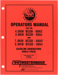
The colour coding used in the cable will depend on the
cable supplied (see Figure 2-1).
2-1
Installation
NEMA TYPE
HP Part No. 8120-1348
LINE"" BLACK
NEUTRAL= WHITE
GROUND= YELLOW/GREEN
Modei8005B
SCHUKO TYPE
HP Part No. 8120-1689
LINE= BROWN
NEUTRAL= BLUE
GROUND= YELLOW/GREEN
BRITISH STANDARD TYPE
HP Part No. 8120-1351
USED IN AUSTRALIA
HP Part No. 8120-1369
LINE= BROWN
NEUTRAL= BLUE
GROUND= YELLOW/GREEN
LINE= BROWN
NEUTRAL= BLUE
GROUND= YELLOW/GREEN
Figure 2-1. Power Cords
2-13 Operating Environment
nal packing is not available nor re-usable. General Instructions for re-packing are as follows:
2-14 The 80058 will operate within specifications when
the ambient temperature is between ooc and 55oc.
1. Wrap instrument in heavy paper or plastic.
2-15 STORAGE AND SHIPMENT
2. Use strong shipping container. A double wall carton
made of 350-pound test material is adequate.
2-16 The 80058 can be stored or shipped at tempera·
tures between -4ooc and 75oc. The instrument should
be protected from temperature extremes which cause
condensation within the instrument.
3. Use enough shock-absorbing material (3 to 4-inch
layer) around all sides of instrument to provide firm
cushion and prevent movement inside container.
Protect control panel with cardboard.
2-17 If the instrument is to be shipped to a HewlettPackard Sales/Service Office, attach a tag showing owner,
return address, model number and full serial number and
the type of service required. The original shipping carton
and packaging material may be re-usable but the HewlettPackard Sales/Service office will also provide information
and recommendations on materials to be used if the origi~
4. Seal shipping container securely,
2-2
5. Mark shipping container FRAGILE to encourage
careful handling.
6. In any correspondence, refer to instrument by
model number and serial number.
Operation
U'i
t'(
'~, I
'
I
8 9 9
''~6
II
REP. RATE (Hz): Rotary switch selects the upper limit of the
repetition rate and selects external ±triggering or manual triggering.
See note 1.
2
R_EP. RATE VERNIER Provides fine control of internal repetition rate. Counter clockwise rotation of the control reduces the
frequencv.
3
DELAY (s}: Rotary switch selects the lower limit of the range
of pulse delays with respect to the trigger outout. See note 1.
17
AMPLITUDE range: Two switches for selecting the upper
limits of the amplitude of the positive and negative output.
18
AMPLITUDE vernier: Provides fine control of the amplitude
of the negative output pulse. Clockwise rotation of the control
increases the amplitude.
19
LINE: push-for-on-push-for-off switch. The lamp adjacent to
the switch indicates when power is on.
20
4
DELAY VERNIER: Provides fine control of the pulse delay.
Clockwise rotation of the control increases the delay.
TRIGGER INPUT: BNC connector for applying trigger pulses
to, when the REP. RATE switch is in the EXT+ or EXT- position.
5
PULSE WIDTH (s): Rotary switch selects the lower limit of the
range of pulse widths. See note 1.
21
GATE INPUT(--): BNC connector to which the negative gate
signal is applied when synchronously or asynchronously gating the
repetition rate generator.
6
PULSE WIDTH VERNIER: Provides fine control of the pulse
width. Clockwise rotation of the control increases the width.
22
TRIGGER OUTPUT(+}: BNC connector supplies positive
trigger pulses.
7
TRANSITION TIME: Rotary switch selects the lower limit of
the range of both rise and fall times.
·23
TTL OUTPUT: BNC connector supplies TTL compatible
voltage.
8
OFFSET vernier: For adjustment of the positive pulse output
base line.
24
OUTPUT (+): BNC connector supplies positive output pulses.
Maximum external voltage can be applied to this connector is± 10V.
9
OFFSET ON/OFF: Two switches {one for each output) to turn
on or off the de baseline offset voltage.
25
10 OFFSET vernier: for adjustment of the negative pulse output
baseline.
26
11
MAN.: Push button when pressed causes one pulse to be gene·
rated when the REP. RATE switch is in the EXT -MAN position.
12
PULSE MODE.: Three positlon switch for selecting normal,
square wave or double pulse operation.
13
OPER. MODE: Three position switch for selecting synchronised
gating, asynchronised gating or normal (no gating) operating modes.
14
LEADING EDGE: Provides fine control of the transition times
for the leading edges of both positive and negative output pulses.
Clockwise rotation of the control increases the transitiori time.
15
TRAILING EDGE: Provides fine control of the transition times
for the trailing edges of both positive and negative output pulses.
Clockwise rotation of the control increases the transition time.
16
AMPLITUDE vernier: Provides fine control of the amplitude of
the positive output pulse. Counter clockwise rotation of the control
reduces the amplitude.
Figure 3-1. Front Panels Controls and Connectors
3-0
ternal
INT LOAD: Switch for connecting and disconnecting the inson load to both positive and negative output amplifier.
NORM
TTl
COMPL
TTL
: provides the following output formats.
NORM
TTL
OUTPUT(+)
COMP
TTL
n__]___£- -- OV (or offset)
OUTPUT(-·) ~-~---OV(oroffset)
TTL OUTPUT
~__ F\_ ____ OV {or offset)
27
OUTPUT {-): BNC connector supplies positive output pulses.
Maximum external voltage that can be applied to this connector is
± 10V.
Note that switch positions indicated by an asterix ( .. )can be used
for a customer selected range.
Modei8005B
Operation
SECTION Ill
OPERATION
3-1
GENERAL
3-2
Figure 3-1 identifies and gives a brief description
OUTPUT(+)
of the function of the front panel controls, adjustments,
switches and connectors.
:
'
:
DELAY
Figure 3-2. Single Pulse Mode - Typical Output
3-3
REPETITION RATE
3-4 The repetition rate can be generated internally or
established externally by means of an external trigger or
the MANUAL 11 push button.
3-5
Double: In this mode the pulse rate is effectively
doubled, The DELAY control determines by how
much the second pulse is delayed with respect to
the first.
Internal Triggering
3-6 The Model 80058 can establish internally any repetition rate in the range 0.3 Hz to 20 MHz. The desired
repetition rate is achieved by setting the REP. RATE 1
OUTPUT(+)
'
REP RATE VERNIER 2 for the required frequency.
3-7
:
!DELAY I
switch to one of the five possible ranges and adjusting the
Figure 3-3. Double Pulse Mode - Typical Output
External Triggering
Square Wave:
3-8 With the REP RATE 1 switch set to EXT+ or
EXT- the repetition rate can be established by an external signal applied to the TRIGGER INPUT 20. The trigger
In this mode the repetition rate of
the pulse and trigger outputs is halved.
signal may be a sine wave or pulses of either polarity
(compatible with the position of the REP RATE 1 switch)
with a repetition frequency up to 20 MHz. Sine waves
must be of at least 2 volts peak to peak amplitude and
pulses must be at least 1V peak and 15ns wide. The maximum permissible input signal is± 10V peak.
3-9
Figure 3-4. Square Wave Mode - Typical Output
Manual Trigger
3-10 With the REP RATE 1 switch set to the EXT
MAN position each depression of the MANUAL 11 push
button will produce an output pulse (two in the DOUBLE
PULSE MODE).
3-11 Pulse Modes
3-12 The 80058 is capable of operating in any one of
three different pulse modes as dictated by the PULSE
MODE 12 switch;
Norm: In this mode pulses are available at the
output connectors. Their repetition rate, delay
(with respect to trigger output), width, transition
times and amplitude are determined by the front
panel control settings,
3-13 Gating of the REP. RATE GENERATOR
3-14 A front panel switch 13 (OPER. MODE) selects
three modes of operation; SYNCH GATED, NORM or
ASYNCH GATED. In the NORM mode the 80058 functions normally and signals applied to the GATE INPUT 21
have no effect on the instrument. In the SYNCH GATED
mode the rep rate generator is turned off until a negative
signal is applied to the GATE INPUT 21. The first pulse
is coincident with the leading edge of the gate and the
last pulse is of normal width even if the gate signal ends
during the pulse. JntheASYNCH GATED mode the gate
pulse and the output pulses bear no time relationship. A
trigger output is available continuously. Square wave is
not available in the gate mode.
3-1
Operation
Modei8005B
3-15 OUTPUT CONTROLS
GATE !NPUT - - -..
3-16 Amplitude and Offset
OUTPUT(•(
3-17 The maximum pulse amplitude from OUTPUT (+)
24 and OUTPUT(-) 25 is 10 volts including de offset.
Fig·ure 3-7 illustrates which combination of source and
external load impedances will provide the desired amplitude. The source impedance for both OUTPUT(+) and
OUTPUT(-) can be selected by means of the INT LOAD
25 switch. When operating in the 10V range, if changes are
made to the settings of the AMPLITUDE verniers 16 and
18 it is necessary to reset the appropriate OFFSET vernier 8 or 10.
--....J
Figure 3-5. Synchronous Gating of Rep. Rate Generator
GATE INPUT---.
OUTPUT!•)
-----....1
Figure 3-6. Asynchronous Gating of Rep. Rate Generator
3-18 An advantage of the selectable internal load is
that it helps overcome the problems of reflections. For
example, using a 200pF capacitor to simulate the capacitance of an external load, Figure 3-7 illustrates which
output configuration will produce the best results. For
amplitudes up to 5 volts, reflections are more effectively
absorbed when the output is developed across a 50.Q termination from a 50.Q source impedance (configuration 1 ).
For amplitudes above 5 volts, either the 50Q termination
or the internal 50Q. load must be disconnected. In this
case, reflections are more effectively absorbed by using
the internal 50!1 load (configuration 2) as opposed to
using only a 50.Q termination as shown in configuration 3.
3-19 TTL Output
3-20 The TTL OUTPUT connector supplies+4.6V open
circuit voltage when the selector switch 26 is set to TTL
and +4.6V complement when set to TTL. When terminated by 50!1 the TTL voltage is +2.6 volts.
3-21 In order to minimize pulse distortion caused by
interaction from unused outputs, it is necessary to term inate a!! unused outputs with son and, where possible, reduce the amplitude to a minimum.
OFFSH
OUTPUT H 24
OUTPUT 1-1 27
AMP!.ITl.IDt
RANGO
ov
:l!JOmV- L25V
1.25V
SV
125VI2 5V
5Vii0V
600mV - 2 5V
2.5V
lOV
1.25V/2.5V
5VI10V
WOmV--2.5V
2.r,V- IOV
L25V.'2
5VIl0V
--------------,
'
''
CD
.fl..
R~cc~::,
:' ~~
T
I
+100'''
i
:
L '_ _ _
_j
________ j
Figure 3-7. Output Configurations
3-2
•W
•w
• 4V'
!
4V'
Modei8005B
Principles of Operation
SECTION IV
PRINCIPLES OF OPERATION
4-1
GENERAL DESCRIPTION
4-5 In the free running mode the repetition rate genera~
tor operates as follows:
4-2 The basic concept of the Model 80058 pulse
generator is shown in Figure 4-1. The pulse repetition
rate is generated either internally or by an external triggering source. Gating can be effected either synchronously,
by using the gate signal to start and stop the repetition
rate generator, or asynchronously, by using the gate signal
to control the output from the repetition rate generator.
The selector circuit determines the shape and destination
of the rate signal used In the pulse and square wave modes
of operation. In the pulse mode, the delay generator
delays, with respect to the trigger output, the output of
the rep rate generator and applies it to the width generator.
For each output pulse from the delay generator the width
generator issues a pulse with a width as defined by the
front panel control. Each pulse is processed by an inte·
grater (with a time constant which can be varied) to
achieve the desired rise and fall times. In the square wave
mode the delay and width generators are not used and the
square wave signal is applied directly to the integrator. The
final operation involves amplifying and scaling :to achieve
the correct amplitude and source impedance.
4-3
The selected ramp capacitor discharges linearly
through 07 at a rate determined by the setting of
VERNIER R1 and the value of the capacitor. As
the voltage at 07 collector approaches zero,
CR10/CR11 become forward biased causing 05
and 06 to conduct and rapidly recharge the ramp
capacitor. CR10/CR11 become reverse biased so
that 05 and 06 cut off and the discharge cycle
resumes.
4-6
In the externally triggered mode, trigger pulses
are applied to the differential amplifier 01/02 which in
turn switches the Schmitt trigger Q3/A4. Each trigger
pulse produces a positive pulse from 04 which is differ~
entia ted by R 11 /L 1, and inverted by 035. The positive
spikes from 035 cause the base of 05 to rise so that 05
and 06 turn on to produce an output pulse. Each trigger
pulse produces an output pu!.se from 06.
4-7
In the MANUAL mode,Q3 is normally on and 04
off. When the MAN push button is pressed, 04 turns on
and a negative spike is applied to 035 which in turn turns
05 and 06 on to produce an output pulse. An output
pulse is produced each time the manual push button is
pushed.
REPETITION RATE
4-4 The pulse repetition rate is determined by either
one of two possible methods:
a. The free running state of the repetition rate
tor.
4-8
In the NORM operating mode, gate 012/013 is
enabled by 013 being held off. Thus, the pulses from the
repetition rate generator which appear at 012 base are
inverted by 012 and applied to the Pulse delay generator.
Gating is not possible in SQ. WAVE.
genera~
b. The frequency of the input pulses.
SELECTOR
PULSE
LW"'DE
"i._ I
"""'
"''"
"'
GATE
REf' RATE
ENERATOR
SOW,
r-w.J._
"-1MODE
h
f.-.1
sow.
rw_
.ODE
f'ULSE
LU-
MOOE
CIRCUIT
t-
DELAY
f-ULJl
WIDTH
l "'"'"'ONf-- M<~FIERS :
1--
TIME
.LruJll
u:uru
11lJ"
JtiL TTL ().)Tf'UT
ATTEWATORS
r-<
f-< 'If[
OOTPUT!·I
Figure 4-1. Basic Concept
4-1
Principles of Operation
Modei8005B
~"'"
0
oJM
0
010k
0
oJOO
0
03-10
EXT•
"'
""
SCHMITT
TRIGGER
TRIGGER
AM'
03.<>.
"
"'
RS
C3
'" 0
~ko
OOOo
CR12
Ho
EXT•
-25V--C
r---:cc:::----,
GATE INPUT
MAN
CR13
GATE
AMPUFIER
012 ,--------,
GATE
LQO)l;Q_ _ _ _ _ _ .DELAY
1--------.!--t<--~~•NORM
L----'
"'A""'"-------------L::.:"'::''·'~"~r
GEN
Figure 4-2. Repetition Rate Generator and Trigger Input Gating
4-9
pulses are applied to the Pulse delay generator for the duration of the gate signal.
GATING
4-11 In the SYNCH operating mode gate amplifier 08
normally on disables the repetition rate generator. A nega·
tive signal at the GATE INPUT cuts 08 off which enables
the repetition rate generator for the duration of the gate
signal.
4-10 In the ASYNCH mode, gate amplifier 08 normally
'on' disables gate 012/013 so that repetition rate pulses
are blocked. A negative signal at the GATE INPUT turns
08 off, hence gate 012/013 is enabled and repetition rate
4-12 PULSE- SQUARE SELECTOR
+20V
ASYNCH
_su
RATE
SIGNAL---------+-----1
VIA R30
---
03/Qt.'
Jl.._J
-liD-UF- __ll_f"""
iNPUT ID
------<iNTEGRATOR
CIRCUIT
,
AMF---.----,
05
SOR WAVE
I
I
I
MOD£ ONLY -'---L 1
04!--------FER
~06
AND
DIFFERENTIATOR
--L1/R17
03
LJl
RATE
SIGNAL---------+---<f02
ViAQ10
+ 20V
DOUBLE
OIFF AMP
L ---'''-"''"'R1CJ7
h-
--------
'
t--<
..Lll!
_w_
·-·-·-·-·-·-·-·-----------·-·-·-· .......
PULSE/DOUBLE
PULSE MODE ONLY
NORM
saw.
RATE
SiGNAL-VIA 012
I
~}-------------------1 -1-1 ~:L~ 6~NERATOR
- - i.....
Figure 4-3. Pulse- Square Selector Circuit
4-2
TRIGGER OUTPUT
Principles of Operation
Modei8005B
4-13 The purpose of this circuit is, in NORM and
DOUBLE pulse mode, to apply the rep. rate generator out·
put to the delay generator and trigger the out*
put amplifier. Alternatively, in SO WAVE mode, the rep
rate output is effectively disconnected from the delay
generator and the trigger is established by one output from
the flip-flop. The other outputfrom theflip-flop is applied
to the integrator circuits for the production of a fixed
delay, fixed width pulse output. The square wave flip·
flop is disabled in SYNCH gate mode.
RATE INPUT
TO FF
I I I I I I
BASE 03
BASE 04
OUTPUT 04
OUTPUTQ3
4-14 When the PULSE MODE switch (S9) is set to
NORM or DOUBLE pulse, the flip-flop (U1) is disabled.
The gates 014 and 02 are open (0 14 off, 02 on) thus the
rate signal from 012 is applied to the delay generator and
the trigger is established via 02. In setting S9 to SO WAVE
01 is turned off, the flip-flop PRESET goes high, thus the
OUTPUT06
flip-flop is enabled. The complementary outputs of the
flip-flop drive a differential amplifier (03/04). The output
of 03 is differentiated ( L 1/R 17) and applied to the trigger
output amplifier 05. This is turned on only by the nega~
tive spikes and thus the positive spikes are suppressed.
I
OUTPUT 05
Figure 4-4, Square Wave Mode Timing Sequence
4-15 PULSE DELAY GENERATOR
-
-r-1-
016
BUFFER 015
(
SCHMITT
TRIGGER
016,017
016
J.,-
TO BASE 025b
WIDTH
GENERATOR
012
CURRENT
SOURCE
023
J.,-
I
"LI"
TO BASE
DlFFERENTIATOR
021 Lb
,...--
INVERTER
a 24b
WIDTH
GENERATOR
022
---.1
~
SCHMITT
TRIGGER
018.Q19
019
../\_
SWITCH
020
; ~co
l
••
Figure 4-5. Delay Generator
4-3
Principles of Operation
Modei8005B
4-16 The function of the Pulse delay generator is to
provide pulses which are delayed with respect to the repetition rate output. Two outputs supply the width
generator. One carries the delayed pulse only whilst the
other carries both the in-phase and delayed pulses.
of the delay. The inverter 025 responds only to the
negative spike (delayed). Both the output from Q16 and
the positive spike from 025 are applied to the width
generator.
BASE 015
4-17
Initially Schmitt trigger Q16/Q17 holds Q20 on
so that 023 supplies 020 with current and the selected
ramp capacitor remains discharged. On receipt of a pulse
from the repetition rate generator via 015, Schmitt
BASE 016
trigger Q16/Q17 switches and cuts off Q20. The current
COLLECTOR 017
BASE 020
source now charges the selected capacitor. When the ramp
reaches the threshold level of Schmitt trigger 019/018,
Q19/Q18 switch and reset Schmitt trigger Q16/Q17. Thus
BASE 019
020 is turned on discharging the ramp capacitor and re·
JUNCTION R71/R41
setting Schmitt trigger Q18/Q19. It is apparent that
Schmitt trigger Q16/Q17 switches first on the in-phase
_...JI....-..----.L.-.,.---.1..-
pulse and is reset after the required delay. Thus the out·
puts from Q16/Q17 are complementary pulses of dur-
BASE 022
ation dependent upon the delay time. The delay time
range is chosen by selecting different capacitors and fine
adjustment is achieved by varying the current defining
resistance R3. The output from 016 is differentiated by
R41/L7 to give a positive spike coincident with the rep
rate generator output and a negative spike on completion
COLLECTOR 022
4-18
GATE
r
SO WAVE
Figure 4-6. Delay Generator Timing Sequence
WIDTH GENEHATOR
,---
CLOSEO
----l....-----.1...-----
025/026
1-
__n_
~
"""
SCHMITT
TRIGGER
(
Cl=l
0311032
DOUBLE
06/09
l___j
SINGLE
/Rt;Mp-GENERATOR - l
I
I
I
I
I
_j_
BUFFER
024
1-
....__
SCHMITT
TRIGGER
027/026
I
'
I
I
I
I
1
CURRENT
SOURCE
023
l
I
I
I
_/l_
I
; ltcw I
I
• 1..
I
L _ _ _ _ _ _ _j
Figure 4-7. Pulse Width Generator
4-4
SWITCH
030
l
TO PHASE
SELECTOR CCT
Principles of Operation
Modei8005B
4-19 Operation of the width generator is similar to
that of the delay generator. A Schmitt trigger (031/032)
SINGLE PULSE MODE
BASE 024
controls the operation of a ramp generator via a switch
(030). When the ramp reaches the threshold level of
Schmitt trigger 025/026 the resulting change of state
resets the first Schmitt trigger. This in turn resets the ramp
generator which resets the second Schmitt trigger. This
cycle occurs once for each input pulse to Schmitt trigger
031/032.
BASE 025
BASE 031
BASE 030
BASE 028
4-20 In the SINGLE pulse mode, gate 025/026 is
closed so that only the delayed output from the delay
generator reaches Schmitt trigger 031/032 via 024.
COLLECTOR 031
OOL.BLE PULSE MODE
I
BASE 031
BASE 030
4-21 In the DOUBLE pulse mode 026 is held off so
that 025 can be turned on by the in-phase output from
the delay generator. Consequently, two pulses reach
Schmitt trigger 031/032; first the in-phase output from
the delay generator via 025 and then the delayed output
via 024.
BASE 028
COLLECTOR 031
Figure 4-8. Width Generator Timing Sequence
4-22 PULSE DEFINING CIRCUITS
•2SV
I
CONTROl
!PHAsSSELITfOO- -----;
''
_j1JtJ
I'
"-'-'--l ~J~
Cfl:>I,-CR35
-·
NORM :-
1----1
-25V
GATE 07
CR14-CR15
tn<ITROL
SCHMITT
TRK>GER
01102
r
i'
_____________________________________________ _;i
PU..SE i¥1XJE 'MIE
l
'IOOto!
1-Yl LEA~NG EOO€
CCM'l: !•VlTRAIUNG EDGE
Figure 4-9. Phase Defining Circuit and Integrator
4-5
Modei8005B
Principles of Operation
4-23 The function of the phase selector is to determine whether the leading edge of the output pulses
are to be positive-going or negative-going (OPE R MODE}.
The purpose of the integrator circuit is, in all modes of
operation, to vary the rise and fall or fall and rise of the
pulse LEADING EDGE and TRAILING EDGE within a
selected range (TRANSITION TIME).
4-24 Pulse and Double Pulse Mode
4-25 For each positive pulse input from the width
generator, a differential amplifier (08/09) produces an
in-phase and an antiphase output. When the OPER. MODE
switch (88) is set to NORM, the output selector passes
only the inphase signal via CR14 or, when 88 is set to
COMPL, the antiphase signal via CR15. With the PULSE
MODE switch 12 set to NDRM or DOUBLE, the gate
07 is open (07 off) and thus the selected signal I via CR14
or CR15) is applied to a Schmitt trigger (01/02).
limits the voltage to which CT can charge to -8.4 V
whilst CR9 limits the discharge potential to +0.7V. The
charging rate and negative clamp voltage define the pulse
risetime whilst the discharge rate and positive clamp voltage define the pulse fall time.
4-30 When the OPER MODE switch (S8) is set to
NORM, the LEADING EDGE vernier is connected to
016 and the T RAI Ll NG EDGE vernier to 011. When
this switch is set to COMPL, the leading edge vernier is
connected to 011 and the trailing edge vernier to 016.
TRIGGER TIMING
INPUT to 08
PHASE SELECTOR
08!09 -CR14/CR15
rNORM ~.-A--,.-1--r
i
CR14
4-26 When switched by the in-phase signal, the Schmitt
trigger produces a positive pulse or, when switched by the
antiphase signai(CR15), a negative pulse.
OUTPUT
OR
lcpR~~L
-.1-..--.L..,--.J...
NORM
'l.J'"!....rL
4-27 Square Wave Mode
PULSE
4-28 By setting the PULSE MODE switch to SO
WAVE the gate 07 is closed (07 turned on), thus the
signal from the width generator is blocked and the Schmitt
trigger disabled. The signals appearing at the base of 04
in this mode are derived from the flip-flop U1 and
differentiated by L1/R4.
-
l
OR
COMPL~
INTEGRATOR INPUT
I bose 04)
OR
SQR WAVE { N::M
.J
COMPL -JL-----,------L4-29 In all ~odes of operation, C3 and R10 reduce
ringing on all but the 10ns range where they would slow
down the transition times. 04 and CR2 convert the single
pulse train to two, each with a different de level. These
two outputs control the switches 06 and 07. Voltage
sources 012, 013, 014 and 016, 017, 018 define the
switching potentials of 06 and 07 respectively, During
the positive excursion 06 is off and 07 is on causing 016
to draw current from the transition time capacitor (CT}
at a rate determined by the capacitance of CT and the
position of the selected transition time vernier. During
the negative duration of the output from 04, 06 turns on
and 07 cuts off. Thus current flows from 011 into CT at
a rate determined by CT and the position of the selected
transition time vernier. Voltage source Q19 and 020
4-6
PULSE {N::M
JLJLJ
COMPL~
INTEGRATOR OUTPUT
OR
SQR WAVE
{N::M _/
COMPL
\\._.....Jf
l
Figure 4-10. Pulse Defining Sequence
Principles of Operation
Mode18005B
4-31 OUTPUT STAGE
FROM
OJTPUT {+)
TRANSITION
g~~INING
'--""'"-"---'
OUTPUT I_- I
Figure 4-11. Output Stage
4-32 Complementary emitter follower 010/011 functions as a buffer stage between the transition time definition circuit and the output stage. The signal from 011
emitter supplies the positive channel (via 012 and complementary emitter follower 016/017) and the negative
channel (via complementary emitter follower 025/026).
CR28 shifts the signal level to the negative stage by
-8.25V. Voltage source 014/015 sets the position of the
positive channel baseline (without offset).
4-33 The output amplifier comprises two differential
amplifiers one in the positive channel (0'18-020) and
one in the negative channel (027-029 and 034). Each
amplifier is supplied from its own current source 022/
023 and 030/031. The switching characteristics of the
respective amplifier are improved by means of the diodes
CR20-CR24 positive channel, and CR29-CR32 in the
negative channeL The amplifiers feed the attenuators via
the AMPLITUDE VERNIER.
4-34 TTL OUTPUT
4-35 The +4.5V TTL output voltage is taken from the
collector of 018 and developed across a 50Q impedance
(R123/R124).
4-36 DC OFFSET
4-37 The de offset circuits control the baseline positions
of the positive and negative outputs. Both circuits operate
in identical fashion, thus only the positive offset circuit
is described. With the offset switch in the OFF position,
the bias potential of Ul is held at OV and the whole circuit is thus off. With the offset switch in the ON position
the bias potential of U1 is dependent on the position of
the OFFSET VERNIER. As the wiper of the OFFSET
VERNIER is moved towards the R31 end, the output of
03/04 goes positive. Similarly, as it is moved towards
R32, the output of 03/04 goes negative.
4-38 POWER SUPPLY
4-39 The +25V and -25V power supplies are identical
series regulated types. An error amplifier compares a
sample of the output with the voltage of a zener diode
and the resulting error signal controls the series regulator
to compensate for any variations.
4-40 The +20V supply is derived from the +25V supply.
R81, and R82 define the potential of 20V at the emitter
of 03. 03 supplies the current.
4-7
Performance Tests
Modei8005B
SECTION V
PERFORMANCE TESTS
5-1
INTRODUCTION
5-7
PERFORMANCE TESTS
5-2
The procedures in this section test the electrical
5-8
The performance tests given in this section are
performance of the instrument using the specifications of
Table 1-2 as performance standards. All tests can be per-
suitable for incoming inspection, troubleshooting, or preventive maintenance. During any performance test, all
formed without access to the interior of the instrument.
shields and connecting hardware must be in place. The
tests are designed to verify the published instrument
specifications. Perform the tests in the order given and
record the data on the test card and/or in the data spaces
provided at the end of each procedure.
5-3
EQUIPMENT REQUIRED
5-4
Equipment required for the performance tests is
listed in Table 1-1, Recommended Test Equipment, Any
equipment that satisfies the critical specifications given in
the table may be substituted for the recommended
model(s).
5-5
NOTE
The instrument must have a 15 min warmup time and the
line voltage must be within +10%; -15% of nominal if
the performance tests are to be considered valid.
TEST RECORD
5-6
Results of the performance tests may be tabulated on the Test Record at the end of the test procedures.
The Test Record lists all of the tested specifications and
their acceptable limits. Test results recorded at incoming
inspection can be used for comparison in periodic maintenance, troubleshooting, and after repairs or adjustments.
5-9 Each test is arranged so that the specification is
written as it appears in Table 1-2. Next, a description
of the test and any special instructions or problem areas
are included. Each test that requires test equipment has
a setup drawing and a list of the required equipment. The
initial steps of each procedure give contro_l settings required for that particular test.
5-1
Mode18005B
Performance Tests
PERFORMANCE TESTS
5-10 Repetition Rate
SPECIFICATION:
0.3 Hz to 20 MHz in five ranges. Vernier provides continuous adjustment within each range.
COUNTER
800"
PULSE GENERATOR
TRIG
23
son
TERMINATION
'--1
-----~
10503A
PROCEDURE:
1.
Set the 80058 controls as follows:
REP RATE 1 . . . . . . . . . . . . . . . . . . . . . . . . . . . . . . . . . . . . . . . . . . . . . . . . . . . . . . . . . . 20M
VERNIER2 . . . . . . . . . . . . . . . . . . . . . . . . . . . . . . . . . . . . . . . . . . . . . . . . . . . . . . . . . . . CW
PULSE DELAY 3 . . . . . . . . . . . . . . . . . . . . . . . . . . . . . . . . . . . . . . . . . . . . . . . . . . . . . . . 0.11'
VERNIER4 . . . . . . . . . . . . . . . . . . . . . . . . . . . . . . . . . . . . . . . . . . . . . . . . . . . . . . . . . . CCW
PULSE WIDTH 5 . . . . . . . . . . . . . . . . . . . . . . . . . . . . . . . . . . . . . . . . . . . . . . . . . . . . . . . . 25n
VERNIER 6 . . . . . . . . . . . . . . . . . . . . . . . . . . . . . . . . . . . . . . . . . . . . . . . . . . . . . . . . . . CCW
TRANSITION TIME 7 . . . . . . . . . . . . . . . . . . . . . . . . . . . . . . . . . . . . . . . . . . . . . . . . . . . . 10n
OFFSET VERNIER 6 . . . . . . . . . . . . . . . . . . . . . . . . . . . . . . . . . . . . . . . . . . . . . . . . . . . . . . OFFSET SWITCH 9 . . . . . . . . . . . . . . . . . . . . . . . . . . . . . . . . . . . . . . . . . . . . . . . . . . . . . OFF
OFFSET VERNIER 10 . . . . . . . . . . . . . . . . . . . . . . . . . . . . . . , . . . . . . . . . . . . . . . . . . . . . . MAN11 . . . . . . . . . . . . . . . . . . . . . . . . . . . . . . . . . . . . . . . . . . . . . . . . . . . . . . . . . . . . . . . PULSE MODE 12 . . . . . . . . . . . . . . . . . . . . . . . . . . . . . . . . . . . . . . . . . . . . . . . . . . , . . NORM
OPER MODE 13 . . . . . . . . . . . . . . . . . . . . . . . . . . . . . . . . . . . . . . . . , . . . . . . . . . . . . NORM
LEADING EDGE 14 . . . . . . . . . . . . . . . . . . . . . . . . . . . . . . . , . . . . . . . . . . . . . . . . . . . . . CCW
TRAILING EDGE 15 . . . . . . . . . . . . . . . . . . . . . . . . . . . . . . . , . . . . . . . . . . . . . . • . . . . . CCW
AMPLITUDE VERNIER 16 . . . . . . . . . . . . . . . . . . . . . . . . . . . . . . . . . . . . . . . . . . . . . . . . . CW
AMPLITUDE RANGE 17 . . . . . . . . . . . . . . . . . . . . . . . . . . . . . . . . . . . . . . . . . . . . . . . • . . 5V
AMPLITUDE VERNIER 18 . . . . . . . . . . . . . . . . . . . . . . . . . . . . . . . . . . . . . . . . . . . . . . . . . CW
INT LOAD 25 . . . . . . . . . . . . . . . . . . . . . . . . . . . . . . . . . . . . . . . . . . . . . . . . . . . . . . . . . . ON
NORM-COMPL 26 . . . . . . . . . . . . . . . . . . . . . . . . . . . . . . . . . . . . . . . . . . . . . . . . . . . NORM
2.
Check the repetition rate for each of the following control settings listed below.
REP RATE 1
20M
0.3M
10k
3.
CW
cw
cw
RESULT
>20 MHz
>300kHz
>10kHz
Set the counter to period measurement and continue checking rep rate
300
0.3-10
5-2
VERNIER 2
cw
< 3.33ms
CW
<lOOms
Modei8005B
Performance Tests
PERFORMANCE TESTS
5-11 Manual Trigger
SPECIFICATION: Push button for generating single pulse (two in double pulse mode).
OSCILLOSCOPE
80058
PULSE GENERATOR
TRIG
23
'
24
22
A
wn
TERMINATION
"-·--
,.._
8
En
t---:1
10503A
10503A
10503A
PROCEDURE:
1.
Set the 80058 controls as follows:
REP RATE 1 . . . . . . . . . . . . . . . . . . . . . . • . . . . . . . . . . . . . . . . . . . . . . . . . . . . . . . . . . EXT+
VERNIER 2 . . . . . . . . . . . . . . . . . . . . . . . . . . . . . . . . . . . . . . . . . . . . . . . . . . . . . . . . . . CCW
PULSE DELAY 3 . . . . . . . . . . . . . . . . . . . . . . . . . . . . . . . . . . . . . . . . . . . . . . . . . . . . . . . . 0.1
VERNIER 4 . . . . . . . . . . . . . . . . . . . . . . . . . . . . . . . . . . . . . . . . . . . . . . . . . . . . . . . . . . CCW
PULSE WIDTH 5 . . . . . . . . . . . . . . . . . . . . . . . . . . . . . . . . . . . . . . . . . . . . . . . . . . . . . . . . 3!1
VERNIER 6 . . . . . . . . . . . . . . . . . . . . . . . . . . . . . . . . . . . . . . . . . . . . . . . . . . . . . . . . . . CCW
TRANSITION TIME 7 . . . . . . . . . . . . . . . . . . . . . . . . . . . . . . . . . . . . . . . . . . . . . . . . . . . . 10n
OFFSET VERNIER 8 . . . . . . . . . . . . . . . . . . . . . . . . . . . . . . . . . . . . . . . . . . . . . . . . . . . . . . OFFSET SWITCH 9 . . . . . . . . . . . . . . . . . . . . . . . . . . . . . . . . . . . . . . . . . . . . . . . . . . . . . OFF
OFFSET VERNIER 10 . . . . . . . . . . . . . . . . . . . . . . . . . . . . . . . . . . . . . . . . . . . . . . . . . . . . . MAN 11 . . . . . . . . . . . . . . . . . . . . . . . . . . . . . . . . . . . . . . . . . . . . . . . . . . . . . . . . . . . . . · · PULSE MODE 12 . . . . . . . . . . . . . . . . . . . . . . . . . . . . . . . . . . . . . . . . . . . . . . . . . . . . . NORM
OPER MODE 13 . . . . . . . . . . . . . . . . . . . . . . . . . . . . . . . . . . . . . . . . . . . . . . . . . . . . . NORM
LEADING EDGE 14 . . . . . . . . . . . . . . . . . . . . . . . . . . . . . . . . . . . . . . . . . . . . . . . . . . . . . CCW
TRAILING EDGE 15 . . . . . . . . . . . . . . . . . . . . . . . . . . . . . . . . . . . . . . . . . . . . . . . . . . . . CCW
AMPLITUDE VERNIER 16 . . . . . . . . . . . . . . . . . . . . . . . . . . . . . . . . . . . . . . . . . . . . . . . . . CW
AMPLITUDE RANGE 17 . . . . . . . . . . . . . . . . . . . . . . . . . . . . . . . . . . . . . . . . . . . . . . . . . . 5V
AMPLITUDE VERNIER 18 . . . . . . . . . . . . . . . . . . . . . . . . . . . . . . . . . . . . . . . . . . . . . . . . . CW
INT LOAD 25 . . . . . . . . . . . . . . . . . . . . . . . . . . . . . . . . . . . . . . . . . . . . . . . . . . . . . . . . . . ON
NORM-COMPL 26 . . . . . . . . . . . . . . . . . . . . . . . . . . . . . . . . . . . . . . . . . . . . . . . . . . . NORM
2.
Press the MAN 11 push button
Check that only one pulse is generated for each depression of the MAN button.
Check that no pulse occurs when the button is released.
5-3
Modei8005B
Performance Tests
PERFORMANCE TESTS
5-12 Pulse Width
SPEC IF !CATION:
< 25ns to 3s in five ranges.
Vernier provides continuous adjustment within each range.
OSCILLOSCOPE
SAMPLiNG
OSCILLO·
SCOPE
80058
8005B
PULSE GENERATOR
PULSE GENERATOR
TRIG
23
A
,R
"
1250-0077
1F--50!0 TERMINATION
84S1A
"'
TRIG
TRIG
23
24
•
-
son
27
A
--
TERMINATION
---e
1250-0780-
B
EXT
f:::;'
10503A
10503A
10503A
\0503A
Fast Ranges
10503A
Slow Ranges
PROCEDURE:
1.
Set the 80058 controls as follows:
REP RATE 1 . . . . . . . . . . . . . . . . . . . . . . . . . . . . . . • . . . . . . . . . . . . . . . . . • . . . . . . . . . 20M
VERNIER 2 . . . . . . . . . . . . . . . . . . . . . . . . . . . . . . • . . . . . . . . . . . . . . . . . . . . . . . . . . . CCW
PULSE DELAY 3 . . . . . . . . . . . . . . . . . . . . . . . . . . . . . . . . • . . . . . . . . . . . . . ,., ...... 0.1,u
VERNIER 4 . . . . . . . . . . . . . . . . . . . . . . . . . . . . . . . . . . . . . . . . . . . . . . . • . . . . . . . . . . CCW
PULSE WIDTH 5 . , . . . . . . . . . . . . . . . . . . . . . . . . . . . . . . . . . . . . . . • . . . . . . . . . . . . . . . 25n
VERNIER 6 . . . . . . . . . . . . . . . . . . . . . . . . . . . . . . . • . . . . . . . . . . . . . . . . • . . . • . . . . • CCW
TRANSITION TIME 7 . . . . . . . . . . . . . . . . . . . . • . . . . . . . . . . . . . . . . . . . . . . . . • . . . . . . 10n
OFFSET VERNIER 8 . . . . . . . . . . . . . . • . . . . . . • . . . . . . . . . . . . . . . . . . . . . . . . . . . . • . . . OFFSET SWITCH 9 . . . . . . . . . . . . . . . . . . . . . . . . . . . . . . . . . . . . . . . . . . . . . . . . . . . • . OFF
OFFSET VERNIER 10 . . . . . . . . . . . . . . • . . . . . . . . . . . . . . . . . . . . . . . . . . . • . . . • . . . . . . MAN 11 . . . . . . . . . . . . . . . . . . . . . . . . . . . , . . . . . . . . . . . . . . . . . • . . • . . . . . . . . . . . . . . PULSE MODE 12 . . . . . . . . . . . . . . . . . . . . . . . . . . . . . . . . . . . . . . . . . . . . . . . . . . . . . NORM
OPER MODE 13 . . . . . . . . . . . . . • . . . . . . , . . . . . . . . . . . . . . . . . . . . . . . . . . . . . . . . NORM
LEADING EDGE 14 . . . . . . . . . . . . . . . . . . . . . . . . . . . . . . . . . . . . . . . . . . . • . . . . . . . . . CCW
TRAILING EDGE 15 . . . . . . . . . . . . . . . . . . . . . . . . . . . . . . . . . . . . . . . . . . . . . . . . . . . • CCW
AMPLITUDE VERNIER 16 . . . . . . . . . • • . . . . . . . . . . . . . . . . . . . . . . • . . . . • . . . . . . . . • . CW
AMPLITUDE RANGE 17 . . . . . . . . . . . . . . . . • . . . . . . . . . . . . . . . . . . . . . . . . . . . . . . . . . 5V
AMPLITUDE VERNIER 18 . . . . . . . . . . . . . . . . . . . . . . . . . . . • . • . . . . . . . . . . . . . . . . . . . CW
INT LOAD 25 . . . . . . . . . . . . . . . . . . . . . . . . . . . . . . . . . . . • • . . . . . . . . . . . . . . . . . . . . . ON
NORM-COMPL 26 . . . . . . . . . . . • . . • . . . • . . . . . . . . . . . . • . . . . . . • . . . . . . . . . . . . NORM
5-4
Performance Tests
Modei8005B
PERFORMANCE TESTS
2.
Using test set*up "fast ranges" check the pulse width for each control setting listed below.
REP RATE 1
20M
0.3M
10K
3.
Using test
set~up
PULSE WIDTH 5
25
3!1
0.1m
VERNIER 6
ccw
ccw
ccw
RESULT
<25ns
< 3J1S
< 0.1ms
"slow ranges" check the pulse width for each control setting listed below.
300
0.3-10
Manual
3m
0.1-3
0.1-3
ccw
ccw
cw
<3ms
< 0.1s
>3s
(switch to EXT+
and press MAN}
5-5
Modei8005B
Performance Tests
PERFORMANCE TESTS
5-13 Pulse Width Jitter
SPECIFICATION:
< 0.1% of any width setting.
OSCILLOSCOPE
""'"
PULSE
.
GENERATOR
TRIG
23
-
" "
A
son
TERMINATION
-
-
a
... t-::1
EXT
10503A
10503A
10503A
PROCEDURE:
1.
Set the 80058 controls as follows:
REP RATE 1 . . . . . . . . . . . . . . . . . . . . . . . . . . . . . . . . , . . . . . . . . . . . . . . . . . . . . . . . . . 10K
VERNIER 2 . . . . . . . . . . . . . . . . . . . . . . . . . . . . . . . . . . . . . . . . . . . . . . . . . . . . . . • . . . . CW
PULSE DELAY 3 . . . . . . . . . . . . . . . . . . . . . . . . . . . . . . . . . . . . . . . . . . . . . . . . . . . . . . . 0.111
VERNIER 4 . . . . . . . . . . . . . . . . . • . . . . . . . . . . . . . . . . . . . . . . . . . . . . . . . . . . . . . . . . CCW
PULSE WIDTH 5 . . . . . . . . . . . . . . . . . . . . . . . . . . . . . . . . . . . . . . . . . . . . . . . . . . . . . . . . 3!1
VERNIER 6 . . . . . . . . . . . . . . . . . . . . . . . . . . . . . . . . . . . . . . . . . . . . . . . , . . . . . . . . . . CCW
TRANSITION TIME 7 . . . . . . . . . . . . . . . . . . . . . . . . . . . . . . . . . . . . . . . , . . . . . . . . . . . . 10n
OFFSET VERNIER 8 . . . . . . . . . . . . . . . . . . . . . . . . . . . . . . . . . . . . . . . . . . . . . . . . . . . . . . OFFSET SWITCH 9 . . . . . . . . . . . . . . . . . . . . . . . . . . . . . . . . . . . . . . . . . . . . . , ....... OFF
OFFSET VERNIER 10 . . . . . . . . . . . . . . . . . . . . . . . . . . . . . . . . . . . . . . . . . . . . . . . . . . . . . MAN 11 . . . . . . . . . . . . . . . . . . . . . . . . . . . . . . . . . . . · .... · · . · · · · · · · · · · · · · · · · · · · · PULSE MODE 12 . . . . . . . . . . . . . . . . . . . . . . . . . . . . . . . . . . . . . . . . . . . . . . . . . . . . . NORM
OPER MODE 13 . . . . . . . . . . . . . . . . . . . . . . . . . . . . • . . . . . . . . . . . . . . . . . . . . . . . . NORM
LEADINGEDGE14 . . . . . . . . . . . . . . . . . . . . . . . . . . . . . . . . . . . . . . . . . . . . . . . . . . . . . CCW
TRAILING EDGE 15 . . . . . . . . . . . . . . . . . . . . . . . . . . . . . . . . . . . . . . . . . . . . . . . . . . . . CCW
AMPLITUDE VERNIER 16 . . . . . . . . . . . . . . . . . . . . . . . . . . . . . . . . . . . , . . . . . . . . . . . , . CW
AMPLITUDE RANGE 17 . . . . . . . . . . . . . . . . . . . . . . . . . . . . . . . . . . . . . . . . . . . . . . . . . . 5V
AMPLITUDE VERNIER 18 . . . . . . . . . . . . . . . . . . . . . . . . . . . . . . . . . . . . . . . . . . . . . . . . . CW
INT LOAD 25 . . . . . . . . . . . . . . . . . . . . . . . . . . . . . . . . . . . . . . . . . . . . . . . . . . . . . . . . . . ON
NORM-COMPL 26 . . . . . . . . . . . . . . . . . . . . . . . . . . . . . . . . . . . . . . . . . • . . . . . . . . . NORM
2.
Set the controls of scope as follows:
MAIN SWEEP
DELAY SWEEP
SWEEP MODE
DELAYED TRIGGER
CM DELAY
5-6
0.1 ms/div.
0.111s/div.
NORM
AUTO
0
3.
Adjust the PULSE WIDTH VERNIER 6 for a pulse width of 0.1 ms on the display.
4.
Move the trailing edge of the first pulse to the centre of the display using the DELAY VERN 1ER 4.
5.
Adjust the scope delay until the intensified spot coincides with the trailing edge of the first pulse.
6.
Switch scope to DELAYED sweep display.
7.
Measure the pulse width jitter.
Modei8005B
Performance Tests
PERFORMANCE TESTS
5-14 Pulse Delay
< 1DOns to 3s
SPECIFICATION:
in five ranges. Vernier provide continuous adjustment within each range.
OSCILLOSCOPE
sooee
PULSE
.
GENERATOR
TRIG
23
"
27
B
A
"""
TERMINATION
-
-
--
.
-
"'
10503A
10503A
10503A
PROCEDURE:
1.
Set the 80058 controls as follows:
REP RATE 1 . . . . . . . . . . . . . . . . . . . . . . . . . . . . . . . . . . . . . . . . . . . . . . . . . . . . . . . . . . 0.3M
VERNIER 2 . . . . . . . . . . . . . . . . . . . . . . . . . . . . . . . . . . . . . . . . . . . . . . . . . . . . . . Mid·travel
PULSE DELAY 3 . . . . . . . . . . . . . . . . • . . . . . . . . . . . . . . . . . . . . . . . . . . . . . . . . . . . . . . 0.11'
VERNIER 4 . . . . . . . . . . . . . . . . . . . . . . . . . . . . . . . . . . . . . . . . . . . • . . . . . . . . . . . . . . . . CW
PULSE WIDTH 5 . . . . . . . . . . . . . . . . . . . . . . . . . . . . . . . . . . . . . . . . . . . . . . . . . . . . . . . . 25n
VERNIER 6 . . . . . . . . . . . . . . . . . . . . . . . . . . . . . . . . . . . . . . . . . . . . . . • . . . . . . . . . • • . CW
TRANSITION TIME 7 . . . . . . . . . . . . . . . . . . . . . . . . . . . . . . . . . . . . . . . • . . . . . • . . . . . . 10n
OFFSET VERNIER 8 ...... , ......•..... , ... , . . . . . . . . . . . . . . . . . . . . . . . . . . . • CCW
OFFSET SWITCH 9 . . . . . . . . . . . . , ... , . . . . . . . . . . . . . . . . . . . . . . . . . . . . . . . . . . . . . . OFFSET VERNIER 10 . . . . . . . . . . . . . . . • . . . . . , .. , . . . . . . . . . . . . . . . . . . . . . . . . , . OFF
MAN11 . . . . . . . . . . . . . . . . . . . . . . . . . . . . . . . . . . . . . . . . . . . . . . . . . . . . . . . . . . . . . . . PULSE MODE 12 ...........•.•.....•....•...•.•..•...•••••••.•.••...• NORM
OPER MODE 13 .... , . . . . . . . . . . . . . . . . . . . , . . . . . . . . . . . . . . . . . . . . . . . . , . , . NORM
LEADING EDGE 14 . . . . . . . . . . . . . . . . . . . . . . . . . . . . . . . . . . . . . . . . . . . . . . . . . . . . . CCW
TRAILING EDGE 15 . . . . . . . . . . . . . . . . . . . . . , ..... , . . . . . . . . . . . . . . . . . . . . , ... CCW
AMPLITUDE VERNIER 16 . , . . . . . . . . . . . . . . . . . . . . . . . . . . . . . . . . . , ............. CW
AMPLITUDE RANGE 17 .. , . . . . . . . . . . . . . . . . . . . . . . . . . . . . . . . . . • . . . . . . . . . . . . . 5V
AMPLITUDE VERNIER 18 . . . . . . . . . . . . • . . . . . . . . . . . . . . . . . . . . . . . . . . . . . . . . . . . . CW
INT LOAD 25 ...... , . . . . . . . • . . . . . . . • . . . . . . • . . . . . . . . . . . . • . . . . . . . . . . . . . . . ON
NORM-COMPL 26 . . . . . . . . . . . . . . . . . . . . . . . . . . . . . . . . . . . . . . . . . . . . , . . . . . . NORM
2.
Set start point of trace to the left side of graticule and measure distance (delay) to the first leading edge.
RATE
DELAY
0.3M
10K
300
0.3-10
EXT-MAN
0.11'
3M
0.1m
3m
0.1-3
VERNIER
cw
CW
cw
CW
cw
WIDTH
25n
3M
0.1m
3m
0.1-3
VERNIER
cw
cw
cw
cw
cw
RESULT
>31'S
>0.1ms
>3ms
>0.1s
>3s
5-7
Modei8005B
Performance Tests
PERFORMANCE TESTS
5-15 Pulse Delay Jitter
SPECIFICATION:
< 0.1% of any delay setting.
OSCILLOSCOPE
80058
PULSE GENERATOR
-
•
TRIG
500
"
24
23
--
TERMINATION
A
8
EXT
l::::;:l
10503A
10503A
10503A
PROCEDURE:
1.
Set the 80058 controls as foUows:
REP RATE 1 . . . . . . . . . . . . . . . . . . . . . . . . . . . . . . . . . . . . . . . • . . . . . . . . . . . . . . . . . . 10K
VERNIER 2 . . . . . . . . . . . . . . . . . . . . . . . • . . . . . . . . . . . . • . . . . . . . . . . • . . . . . . . . . . . CW
PULSE DELAY3 . . . . . . . . . . . . . . . . . . . . . . . . . . . . . • . . . . . . . . . . . . . . . . . . . . . . . . . O.l!l
VERNIER 4 . . . . . . . . . . . . . . . . . . . . . . . . . . • . . . . . . . . . . . . . . . . . . . . . . . . . . . . . . . CCW
PULSEWIDTH5 • . . . . . • . . . . . • . . . . . . . . . . . . . . . . . . . . . . . . . . . . . . . . . . . . . . . . . . . 3!i
VERNIER 6 . . . . . . . . . . . . . . • . . • . • • . . . . . . . . . • . . . . . • . . . . . . . . . . . . . . . . . . . . . . CW
TRANSITION TIME 7 . • . . . . . . . . . . . . . . . . . . . . . . . . • . . . . . . . . . . . . . . . . . . . . . . . . . 10n
OFFSET VERNIER 8 . . . . . . . . . . . . . . . . . . . . . . . . . . . . . . . . . . . . . . . . . . . . . . . . . . . . . . OFFSET SWITCH 9 . . . . . . . . . . . . . . . . . . . . . . . . . . . . . . . . . . . . . . . . . . . . . . . . . . . . . OFF
OFFSET VERNIER 10 . . . . . . . . . . . . . . . . . • . . . . • . . . . . . . . . . . . . . . . . . . . . . . . . . . . . . MAN 11 . . . . . . . . . . . . . . . . . . . . • . . . . . . . . . . . • . . . . . . . . . . . . . . . . . . . . . . . . . . . . . . PULSE MODE 12 • . . . . . . . . . . . . . . . . . . . . . . . . . . . . . . . . . . . . . . . . . . . . . . . . . . . • NORM
OPER MODE 13 . . . . . . . . . . . . . . . . . . . . . . . . • . . . . . . . . . . . . . . . • • . . . • . . . . . . . NORM
LEADING EDGE 14 . . . . . . . . . . . . . . . • . . . . . . . . . . • . • . . . . . . • . . . . • . . . . . . . . . . . . CCW
TRAILING EDGE 15 . . . . . . . . . . . . . . . . . . . . . . . . . . . . . . . . . . . . . . . . . . . . . . . . . . . . CCW
AMPLITUDE VERNIER 16 . . . . . . . . . . . . . . . . . . . . . . . . . . . . . • • . • . . . • . • • . . . . . . . . . CW
AMPLITUDE RANGE 17 . . . . . . . . . . . . . . . • • • . . . . . . . . . . . . . . . . . . . . . . . . . . . . . . . . 5V
AMPLITUDE VERNIER 18 . . . . . . . . . . . . . . . . . . . . . . . . . . . . . . . . . . . . . . . . . . . . . • • . . CW
INT LOAD 25 • . . . . . . . . . . . . . . . . . . . . . . . . . . . . . . . . . . . . . . • • . . • . . . . . . . . • . . . . . ON
NORM-COMPL 26 ...........................•..•.•.....•••.....••.•. NORM
2.
Set the controls of scope as follows:
MAIN SWEEP
DELAY TRIGGER
SWEEP MODE
DELAYED TRIGGER
CM DELAY
TRIGGER
0.1 ms/div
0.1!is/div
NORM
AUTO
0
3.
Adjust the REP RATE VERNIER 2 to obtain a 0.2ms period on the display.
4.
Move the signal 0.1 ms by switching the PULSE DELAY 3 to 3m and adjusting the VERNIER 4 appropriately,
5.
Adjust the 1821A DELAY (DIV) until intensified spot coincides with the leading edge of the second pulse on the
display.
6.
Switch to MIXED sweep display on 1821A.
7.
Measure the pulse delay jitter.
t~<0.1ps
5-8
Model80058
Performance Tests
PERFORMANCE TESTS
5-16 Square Wave
SPECIFICATION
0.15 Hz to 10 MHz. Duty cycle: 50%± 5% for repetition rates,.;; 1 MHz,
increasing to 50%± 15% at 10 MHz.
OSCILLOSCOPE
80058
.
PULSE GENERATOR
TRIG
-
A
500
TERMINATION
" "
23
--·-·- 1:::;:!
'
EXT
10503A
10503A
PROCEDURE:
1.
10503A
Set 80058 controls as follows:
REP RATE 1 . . . . . . . . . . . . . . . . . . . . . . . . . . . . . . . . . . . . . . . . . . . . . . . . . . . . . . . . 0.3-10.
VERNIER 2 ........ , . . . . . . . . . . . , . , . . . . . . . . . . . . . . . . . . . . . . . . . . . . , .... , . CCW
PULSE DELAY 3 ... , ...•.•.. , .. ,.,, .•.. ,, •... ,., • . . . . . . . . . . . . . . . . , ... ,. 0.1/1
VERNIER 4 . . . . . . . . . . . , . . . . . . . , . . . . . . . . . . , . . . . . . . . . . . . . . . . . . . . . . . . . , . CCW
PULSE WIDTH 5 ...... , . . . . . . . . . . . . . . . . . . . . . . . . . . . . . . . . . . , .. , .. , ..... , .. 25n
VERNIER 6 ..... , ...... , ..... , . . . . . . . . . . . . . . . . . . . . . . . . . . . . . . . . , .... , , CCW
TRANSITION TIME 7 ..... , , . . . . . . . . . . . . . . . . . . . . . . . . . . . . . . . . . . . . . . . , .. , , , 10n
OFFSET VERNIER 8 . . . . . . . . . . . . . . . . . . . . . . . . . . . . . . . . . . . . . . . . . . . . . . . , ... , , . OFFSET SWITCH 9 . . . . . . . . . . . . . . . . . . . . . . . . . . . . . . . , . , , , ... , , ........ , ... OFF
OFFSET VERNIER 10 . . . . . . . . . . . . . . . . . . . , ... , , ... , . . . . . . . . . . . . . . . . . . . . . . . . MAN 11 . . . . . . . . . . . . . . . . . . . . . . . . . . . . . . . . . . . . . . . . . . . . . . . . . . . . . . . . . . . . . . . PULSE MODE 12 .. , . ... , , . . . . . . . . . . . . . . . . . . . . . . . . . . . . . . . . . . . . . . , .. , SO WAVE
OPER MODE 13 . . . . . . . . . . . . . . . . . . . . . . . . . , ... , .. , , , , ...... , , , . , ...... NORM
LEADING EDGE 14 . . . . . . . . . . , ... , , , . , , , . . . . . . . . . . . . . . . . . . . . . . . . . . . . . . . . CCW
TRAILING EDGE 15 .. , .. , . . . . . . . . . . . . . . . . . . . . . . . . . . . . . . . . . . . . . . . . . . . . . . CCW
AMPLITUDE VERNIER 16 . . . . . . . . . . . . . . . . . . . . . . . . . . . . . . . . . . . , . , . . . . . . . . . . . CW
AMPLITUDE RANGE 17 .............. , ......... , . , , ...................... 5V
AMPLITUDE VERNIER 18 .... , ... , ....................... , ........ , ..... , . CW
INT LOAD 25 .. , . . . . . . . . . . . . . . . . . . . . . . . . . . . . . . . . . . . . , . , ..... , , . , .. , .. , . ON
NORM-COMPL 26 . . . . . . . . . . . . . . . . . . . . . , ......... , . . . . . . . . . . . . . . . . . . . NORM
2.
For each setting of the REP RATE switch 1 given in the table below, turn the VERNIER 2 and check that the
pulse width (ton) equals the pulse off time (t off).
OUTPUT l+l
JU
I It I
U1
tON
OUTPUT(-)
3.
OFF
REP RATE 1
0.3-10
300
10K
0.3 MHz
20 MHz
VERNIER 2
ccw
ccw
ccw
ccw
ccw
tON = t OFF ± 5%
Turn the vernier slowly CW
and stop at 1 MHz
4.
Turn the vernier fully CW
and measure pulse width
tON=tOFF±15%
5-9
Modei8005B
Performance Tests
PERFORMANCE TESTS
5-17 Duty Cycle
SPEC! FICATION: > 80% for repetition rates from 0.3 Hz to 1 MHz, >50% from 1 MHz to 20 MHz. Up to 100% when
using pulse complement.
OSCILLOSCOPE
800£8
PULSE GENERATOR
•
TRIG
23
"
A
~
500
27
TERMINATION
~"---
.. - .. _..
8
_t::i
EXT
(
10503A
10503A
10503A
PROCEDURE:
1.
Set 80058 controls as follows:
REP RATE 1 . . . . . . . . . . . . . . . . . . . . . . . . . . . . . . . . . . . . . . . . . . . . . . . . . . . . . . . . , . 20M
VERNIER 2 . . . . . . . . . . . . . . . . . . . . . . . . . . . . . . . . . . . . . . . . . . . . . . . . . . . . . . . . . . . CW
PULSE DELAY 3 . . . . . . . . . . . . . . . . . . . . . . . . . . . . . . . . . . . . . . . . . . . . . . . . . . . . . . . 0.111
VERNIER 4 . . . . . . . . . . . . . . . . . . . . . . . . . . . . . . . . . . . . . . . . . . . . . . • . . . . . . . . . . • CCW
PULSE WIDTH 5 . . . . . . . . . . . . . . . . . . . . . . . . . . . . . . . . . . . . . . . . . . . . . . . . . . . . . . . . 25n
VERNIERS . . . . . . . . . . . . . . . . . . . . . . . . . . . . . . . . . . . . . . . . . . . . . . . . . . . . . . . . . . CCW
TRANSITION TIME 7 . . . . . . . . . . . . . . . . . . . . . . . . . . . . . . . . . . . . . . . . . . . . . . . . . . . . 10n
OFFSET VERNIER 8 . . . . . . . . . . . . . . . . . . . . . . . . . . . . . . . . . . . . . . . . . . . . . . . . . . . . . . OFFSET SWITCH 9 . . . . . . . . . . . . . . . . . . . . . . . . . , . . . . . . . . . . . . . . . . . . . . . . . . . . . OFF
OFFSET VERNIER 10 . . . . . . . . . . . . . . . . . . . . . . . . . . . . . . . . . . . . • . . . . . . . . . . . . . . . . MAN 11 . . . . . . . . . . . . . . . . . . . . . . . . . . . . . . . . . . . . . . . . . . . . . . . . . . . . . . . . · ·. · · · ·
PULSE MODE 12 . . . . . . . . . . . . . . . . . . . . . . . . . . . . . . . . . . . . . . . . . . . . . . . . . . . . . NORM
OPER MODE 13 . . . . . . . . . . . . . . . . . . . . . . . . . . . . . . . . . . . . . . . . . . . . . . . . . . . . . NORM
LEADING EDGE 14 . . . . . . . . . . . . . . . . . . . . . . . . . . . . . . . . . . . . . . . . . . . . . . . . . . . . . CCW
TRAILING EDGE 15 . . . . . . . . . . . . . . . . . . . . . . . . . . . . . . . . . . . . . . . . . . . . . . . . . . . . CCW
AMPLITUDE VERNIER 16 . . . . . . . . . . . . . . . . . . . . . . . . . . . . . . . . . . . . . . . . . . . . . . . . . CW
AMPLITUDE RANGE 17 . . . . . . . . . . . . . . . . . . . . . . . . . . . . . . . . . . . . . . . . . . . . . . . . . . 5V
AMPLITUDE VERNIER 18 . . . . . . . . . . . . . . . . . . , . . . . . . . . . . . . . . . . . . . . . . . . . . . . . . CW
INT LOAD 25 . . . . . . . . . . . . . . . . . . . . . . . . . . . . . . . . . . . . . . . . . . . . . . . . . . . . . . . . . . ON
NORM-COMPL 26 . . . . . . . . . . . . . . . . . . . . . . . . . . . . . . . . . . . . . . . . . . . . . . . . , . . NORM
5-10
2.
Adjust the REP RATE VERNIER 2 for one complete period over the display area.
3.
Turn the PULSE WIDTH VERNIER 6 slowly CW until the pulse period is affected (count down) and measure
the duty cycle > 50%.
4.
Set the REP RATE 1 and adjust the VERN! E R 2 forfrequencies under 1 MHz and repeat step 2. > 80% 'on-time'.
Performance Tests
Modei8005B
PERFORMANCE TESTS
5-18 Double Pulse
SPECIFICATION: 10 MHz max (simulates 20M Hz) spacing:< lOOns to 3s (with respect to trigger output) in five ranges.
Vernier provides continuous adjustment within each range.
OSCILLOSCOPE
80058
PULSE GENERATOR
TRIG
23
,. '
-
A
"
'
.. 1":::;1
500
TERMINATION
m
10503A
10503A
10503A
PROCEDURE:
1.
Set 80058 controls as follows:
REP RATE 1 . . . . . . . . . . . . . . . . . . . . . . . . . . . . . . . . . . . . . . . . . . . . . . . . . . . . . . . . . . 20M
VERNIER 2 . . . . . . . . . . . . . . . . . . . . . . . . . . . . . . . . . . . . . . . . . . . . . . . . . . . . . . . . . . CCW
PULSE DELAY 3 . . . . . . . . . . . . . . . . . . . . . . . . . . . . . . . . . . . . . . . . . . . . . . . . . . . . . . . 0.1p
VERNIER 4 . . . . . . . . . . . . . . . . . . . . . . . . . . . . . . . . . . . . . . . . . . . . . . . . . . . . . . . . . . CCW
PULSE WIDTH 5 . . . . . . . . . . . . . . . . . . . . . . . . . . . . . . . . . . . . . . . . . . . . . . . . . . . . . . . . 25n
VERNIERS . . . . . . . . . . . . . . . . . . . . . . . . . . . . . . . . . . . . . . . . . . . . . . . . . . . . . . . . . . CCW
TRANSITION TIME 7 . . . . . . . . . . . . . . . . . . . . . . . . . . . . . . . . . . . . . . . . . . . . . . . . . . . . 10n
OFFSET VERNIER 8 . . . . . . . . . . . . . . . . . . . . . . . . . . . . . . . . . . . . . . . . . . . . . . . . . . . . . .
OFFSET SWITCH 9 . . . . . . . . . . . . . . . . . . . . . . . . . . . . . . . . . . . . . . . . . . . . . . . . . . . . . OFF
OFFSET VERNIER 10 . . . . . . . . . . . . . . . . . . . . . . . . . . . . . . . . . . . . . . . . . . . . . . . . . . . . . MAN 11 . . . . . . . . . . . . . . . . . . . . . . . . . . . . . . . . . · · · · · · · · · · · · · · · · · · · · · · · · · · · · · · PULSE MODE 12 . . . . . . . . . . . . . . . . . . . . . . . . . . . . . . . . . . . . . . . . . . . . . . . . . . . . DOUBLE
OPER MODE 13 . . . . . . . . . . . . . . . . . . . . . . . . . . . . . . . . . . . . . . . . . . . . . . . . . . . . . NORM
LEADING EDGE 14 . . . . . . . . . . . . . . . . . . . . . . . . . . . . . . . . . . . . . . . . . . . . . . . . . . . . . CCW
TRAILING EDGE 15 . . . . . . . . . . . . . . . . . . . . . . . . . . . . . . . . . . . . . . . . . . . . . . . . . . . . CCW
AMPLITUDE VERNIER 16 . . . . . . . . . . . . . . . . . . . . . . . . . . . . . . . . . . . . . . . . . . . . . . . . . CW
AMPLTIUDE RANGE 17 . . . . . . . . . . . . . . . . . . . . . . . . . . . . . . . . . . . . . . . . . . . . . . . . . . 5V
AMPLITUDE VERNIER 18 . . . . . . . . . . . . . . . . . . . . . . . . . . . . . . . . . . . . . . . . . . . . . . . . . CW
!NT LOAD 25 . . . . . . . . . . . . . . . . . . . . . . . . . . . . . . . . . . . . . . . . . . . . . . . . . . . . . . . . . . ON
NORM-COMPL 26 . . . . . . . . . . . . . . . . . . . . . . . . . . . . . . . . . . . . . . . . . . . . . . . . . . . NORM
2.
Check pulse spacing.
.
I
--}t_A--I1 <sons
.
I
1
•I
5-11
Performance Tests
Modei8005B
PERFORMANCE TESTS
5-19 Transition Times (Fast)
SPECIFICATION:~
10ns to 2s in six ranges. Separate verniers provide independent control of leading and trailing edges
within each range. Ranges are common for leading and trailing edges. Max. leading edge/trailing edge
ratio, 1 :30 or 30:1.
SAMPLING
OSCILLOSCOPE
BOOSB
PULSE GENERATOR
TRIG
" "
m
A
,{:;
~50[l TERMINATION
TRIG
1250---0077
8491A
------.
1250-0780------<
10503A
10503A
PROCEDURE:
1.
Set 80058 controls as follows:
REP RATE 1 . . . . . . . . . . . . . . . . . . . . . . . . . . . . . . . . . . . . . . . . . . . . . . . . . . . . . . . . . . . 20M
VERNIER2 . . . . . . . . . . . . . . . . . . . . . . . . . . . . . . . . . . . . . . . . . . . . . . . . . . . . . . . . . . . CCW
PULSE DELAY 3 . . . . . . . . . . . . . . . . . . . . . . . . . . . . . . . . . . . . . . . . . . . . . . . . . . . . . . . . 0.11'
VERNIER 4 . . . . . . . . . . . . . . . . . . . . . . • . . . . . . . . . . . . . . . . . . . . . . . . . . . . . . . . . . . . CCW
PULSE WIDTH 5 . . . . . . . . . . . . . . . . . . . . . . . . . . . . . . . . . . . . . . . . . . . . . . . . . . . . . . . . . 25n
VERNIER 6 . . . . . . . . . . . . . . . . . . . . . . . . . . . . . . . . . . . . . . . . . . . . . . . . . . . . . . . . . . . CCW
TRANSITION TIME 7 . . . . . . . . . . . . . . . . . . . . . . . . . . . . . . . . . . . . . . . . . . . . . . . . . . . . . 10n
OFFSET VERNIER 8 . . . . . . . . . . . . . . . . . . . . . . . . . . . . . . . . . . . . . . . . . . . . . . . . . . . . . . . OFFSET SWITCH 9 . . . . . . . . . . . . . . . . . . . . . . . . . . . . . . . . . . . . . . . . . . . . . . . . . . . . . . OFF
OFFSET VERNIER 10 . . . . . . . . . . . . . . . . . . . . . . . . . . . . . . . . . . . . . . . . . . . . . . . . . . . . . . MAN 11 . . . . . . . . . . . . . . . . . . . . . . . . . . . . . . . . . . . . · .. · · · · · · · · · · · · · · · · · · ·
PULSE MODE 12 . . . . . . . . . . . . . . . . . . . . . . . . . . . . . . . . . . . . . . . . . . • . . . . . . . . .
OPER MODE 13 . . . . . . . . . . . . . . . . . . . . . . . . . . . . . . . . . . . . . . . . . . . . . . . . . . . ,
LEADING EDGE 14, , , , . , , , , , , , , , , . , ... , , , , , , , , , , .. , , , .. , ..... , , , , , , ,
TRAILING EDGE 15 , , . , , . , . , ... , , , , , , , . , , .. , . , , , .. , , , , , , . , , . , , . , , , , ,
AMPLITUDE VERNIER 16 , , , , , , , , ........ , . , , , , , , , , , , , ....... , ...... , ,
AMPLITUDE RANGE 17 ... , . , .. , ... , , .... , . , .... , , , , , .. , . , , .. , .... , , .
AMPLITUDE VERNIER 18 , , , . , . , ..... , ... , , , , . , .......... , , , , . , ... , ...
INT LOAD 25 , , . , . , ... , , .. , , , ......... , .. , , , . , .. , ..... , ....... , . , , .
NORM-COMPL 26 ...... , , . , , , . , , , ..... , ........... , . , . , , , , ...... , ..
5-12
2.
Adjust the amplitude for a full screen display,
3.
Expand the display and measure the transition times< 10ns.
4.
Repeat the measurements for the negative output< 1Ons.
5.
Return the scope to X1 expansion.
6.
Switch the TRANSITION TIME 7 switch to 0.1Ms.
7.
Measure the transition times of both + and - outputs< 1OOns.
·· ··· · SO WAVE
.. NORM
, , , , CCW
. , , , CCW
. , . , . CW
, . , , . 5V
, , , , , CW
, . , , . ON
, . NORM
Modei8005B
Performance Tests
PERFORMANCE TESTS
5-20 Transition Linearity
SPECIFICATION: For transition times> 30ns, maximum amplitude deviation from a straight line between the 10% and
90% points is less than 4% of pulse amplitude.
SAMPLING
OSCILLO
SCOPE
""""
PULSE GENERATOR
TRIG
" "
<
nR
~
A
EXT
TRIG
1250-0017
50>1 TERMINATION
8491A
---
1?50--0780 ...............
10503A
10503A
PROCEDURE:
1.
Set 80058 controls as follows:
REP RATE 1 . . . . . . . . . . . . . . . . . . . . . . . . . . . . . . . . . . . . . . . . . . . . . . . . . . . . . . . . . . 20M
VERNIER 2 . . . . . . . . . . . . . . . . . . . . . . . . . . . . . . . . . . . . . . . . . . . . . . . . . . . . . . . . . . CCW
PULSE DELAY 3 . . . . . . . . . . . . . . . . . . . . . . . . . . . . . . . . . . . . . . . . . . . . . . . . . . . . . . . 0.1J.l
VERNIER 4 . . . . . . . . . . . . . . . . . . . . . . . . . . . . . . . . . . . . . . . . . . . . . . . . . . . . . . . . . . CCW
PULSE WIDTH 5 . . . . . . . . . . . . . . . . . . . . . . . . . . . . . . . . . . . . . . . . . . . . . . . . . . . . . . . . 25n
VERNIER 6 . . . . . . . . . . . . . . . . . . . . . . . . . . . . . . . . . . . . . . . . . . . . . . . . . . . . . . . . . . CCW
TRANSITION TIME 7 . . . . . . . . . . . . . . . . . . . . . . . . . . . . . . . . . . . . . . . . . . . . . . . . . . . 0.1J.l
OFFSET VERNIER 8 . . . . . . . . . . . . . . . . . . . . . . . . . . . . . . . . . . . . . . . . . . . . . . . . . . . . . . OFFSET SWITCH 9 . . . . . . . . . . . . . . . . . . . . . . . . . . . . . . . . . . . . . . . . . . . . . . . . . . . . . OFF
OFFSET VERNIER 10 . . . . . . . . . . . . . . . . . . . . . . . . . . . . . . . . . . . . . . . . . . . . . . . . . . . . . MAN11 . . . . . . . . . . . . . . . . . . . . . . . . . . . . . . . . . . . . . . . . . . . . . . . . . . . . . . . . . . . . . . . PULSE MODE 12 . . . . . . . . . . . . . . . . . . . . . . . . . . . . . . . . . . . . . . . . . . . . . . . . . . . SQ WAVE
OPER MODE 13 . . . . . . . . . . . . . . . . . . . . . . . . . . . . . . . . . . . . . . . . . . . . . . . . . . . . . NORM
LEADING EDGE 14 . . . . . . . . . . . . . . . . . . . . . : . . . . . . . . . . . . . . . . . . . . . . . . . . . . . . . CCW
TRAILING EDGE 15 . . . . . . . . . . . . . . . . . . . . . . . . . . . . . . . . . . . . . . . . . . . . . . . . . . . . CCW
AMPLITUDE VERNIER 16 . . . . . . . . . . . . . . . . . . . . . . . . . . . . . . . . . . . . . . . . . . . . . . . . . CW
AMPLITUDE RANGE 17 . . . . . . . . . . . . . . . . . . . . . . . . . . . . . . . . . . . . . . . . . . . . . . . . . . 5V
AMPLITUDE VERNIER 18 . . . . . . . . . . . . . . . • . . . . . . . . . . . . . . . . . . . . . . . . . . . . . . . . . CW
INT LOAD 25 . . . . . . . . . . . . . . . . . . . . . . . . . . . . . . . . . . . . . . . . . . . . . . . . . . . . . . . . . . ON
NORM-COMPL26 . . . . . . . . . . . . . . . . . . . . . . . . . . . . . . . . . . . . . . . . . . . . . . . . . . . NORM
2.
Adjust the amplitude for a full screen display.
3.
Centre the leading edge of the pulse on the display.
4.
With reference to the diagram check the transition linearity
Devi·ation to be< 4% of pulse amplitude
5.
Centre the trailing edge on the display.
10%-
6.
Repeat steps 2 to 4 for OUTPUT(-).
5-13
Modei8005B
Performance Tests
PERFORMANCE TESTS
5-21 Preshoot, Overshoot and Ringing
SPECIFICATION: overshoot, preshoot and ringing each less than 5% of pulse amplitude.
SAMPLING
OSCILLO·
SCOPE
"""'"
PULSE GENERATOR
m
TRIG
" " ,R
~50£<
1250-0077
TERMINATION
84S1A
'
TRIG
-------.
1250-0780-------<
10503A
10503A
PROCEDURE:
1.
Set 80058 controls as follows:
REP RATE 1 . . . . . . . . . . . . . . . . . . . . . . . . . . . . . . . . . . . . . . . . . . . . . . . . . . . . . . . . . . 20M
VERNIER2 . . . . . . . . . . . . . . . . . . . . . . . . . . . . . . . . . . . . . . . . . . . . . . . . . . . . . . . . . . CCW
PULSE DELAY 3 . . . . . . . . . . . . . . . . . . . . . . . . . . . . . . . . . . . . . . . . . . . . . . . . . . . . . . . 0.111
VERNIER 4 . . . . . . . . . . . . . . . . . . . . . . . . . . . . . . . . . . . . . . . . . . . . . . . . . . . . . . . . . . CCW
PULSE WIDTH 5 . . . . . . . . . . . . . . . . . . . . . . . . . . . . . . . . . . . . . . . . . . . . . . . . . . . . . . . . 25n
VERNIER 6 . . . . . . . . . . . . . . . . . . . . . . . . . . . . . . . . . . . . . . . . . . . . . . . . . . . . . . . . . . CCW
TRANSITION TIME 7 . . . . . . . . . . . . . . . . . . . . . . . . . . . . . . . . . . . . . . . . . . . . . . . . . . . . 10n
OFFSET VERNIER 8 . . . . . . . . . . . . . . . . . . . . . . . . . . . . . . . . . . . . . . . . . . . . . . . . . . . . . . OFFSET SWITCH 9 . . . . . . . . . . . . . . . . . . . . . . . . . . . . . . . . . . . . . . . . . . . . . . . . . . . . . OFF
OFFSET VERNIER 10 . . . . . . . . . . . . . . . . . . . . . . . . . . . . . . . . . . . . . . . . . . . . . . . . . . . . . MAN11 . . . . . . . . . . . . . . . . . . . . . . . . . . . . . . . . . . . . . ·· ··· ··· · ·· · · · · · · ·· · · · · · · · PULSE MODE 12 . . . . . . . . . . . . . . . . . . . . . . . . . . . . . . . . . . . . . . . . . . . . . . . . . . . SO WAVE
OPER MODE 13 . . . . . . . . . . . . . . . . . . . . . . . . . . . . . . . . . . . . . . . . . . . . . . . . . . . . . NORM
LEADING EDGE 14 . . . . . . . . . . . . . . . . . . . . . . . . . . . . . . . . . . . . . . . . . . . . . . . . . . . . . CCW
TRAILING EDGE 15 . . . . . . . . . . . . . . . . . . . . . . . . . . . . . . . . . . . . . . . . . . . . . . . . . . . . CCW
AMPLITUDE VERNIER 16 . . . . . . . . . . . . . . . . . . . . . . . . . . . . . . . . . . . . . . . . . . . . . . . . . CW
AMPLITUDE RANGE 17 . . . . . . . . . . . . . . . . . . . . . . . . . . . . . . . . . . . . . . . . . . . . . . . . . . 5V
AMPLITUDE VERNIER 18 . . . . . . . . . . . . . . . . . . . . . . . . . . . . . . . . . . . . . . . . . . . . . . . . . CW
!NT LOAD 25 . . . . . . . . . . . . . . . . . . . . . . . . . . . . . . . . . . . . . . . . . . . . . . . . . . . . . . . . . . ON
NORM-COMPL26 . . . . . . . . . . . . . . . . . . . . . . . . . . . . . . . . . . . . . . . . . . . . . . . . . . . NORM
2.
With reference to the diagram measure the following:
Oversho~!.:L.
a)
b)
c)
3.
5-14
Preshoot
Overshoot
Ringing
Repeat step 1 for OUTPUT(-).
<5%
<5%
<5%
T
Amplj'"d•
~:!
l Ringing
r · "r'-'----~
:Preshoot
L
Modei8005B
Performance Tests
PERFORMANCE TESTS
5-22 Trigger Output
SPECIFICATION: positive pulses> 2V amplitude across external 50 ohm load.
SAMPLING
OSCILLO·
SCOPE
"""'
.
PULSE GENERATOR
TRIG
" " "
m
-
A
TRIG
125tHXl77
8491A
50fl TERMINATION
---o
1250-0780 __,
10503A
10503A
PROCEDURE:
1.
Set 80058 controls as follows:
REP RATE 1 . . . . . . . . . . . . . . . . . • . . . . . . . . . . . . . . . . . . . . . . . . . . . . . . . . . . . . . . . . 20M
VERNIER 2 . . . . . . . . . . . . . . . . . . . . . . . . . . . . • • . . . . . . . . . . . • . . . . . . . . . . . . . . . . CCW
PULSE DELAY 3 . . . . . . . . . . . . . . . . . . . . . . . . . . . . . . . . . . . . . . . . . . . . . . . • . . . . . . • 0.111
VERNIER 4 . . . . . . . . . . . . . . . . . . . . . . . . . . . . . . . . . . . . . . . . . . . . . . • . . . . . . . . . . . CCW
PULSE WIDTH 5 . . . . . . . . . . . . . . . . . . . . . . . . . . . . . . . . . . . . . . . . . . . . . . . . . . . . . . . . 25n
VERNIER 6 . . . . . . . . . . . . . . . . . . . . . . . . . . . . . . . . . . . . . . . . . . . . . . . . . . . • . . . . . . CCW
TRANSITION TIME 7 . . . . . . . . . . . . . . • • . . . . . . . . . . . . . . . . . . . . . . . . . . . . . . . . . . . . 10n
OFFSET VERNIER 8 . . . . . . . . . . . . . . . . . . . . . . . . . . . . . . . . . . . . . . . . . . . . . . . . . . . . . . OFFSET SWITCH 9 ....................· . . . . . . . . . . . . . . . . . . . . . . . . . . . . . . . . . OFF
OFFSET VERNIER 10 . . . . . . . . . . . . . . . . . . . . . . . . . . . . . . . • . . . . . . . • . . . . . . . . . . . . . MAN 11 . . . . . . . . . . . . . . . . . . . . . . . . . . . . . . . . . · · · · · · · · · · · · · · · · · · · · · · · · · · · · ·: PULSE MODE 12 . . . . . . . . . . . . . . . . . . . . . . . . . . . . . . . . . . . . . . • . • . . . . . . . . . . . . NORM
OPER MODE 13 , .............• , . . . . . . . . . . . . . . . . . . . . . . . . . . . . . • . . . . . • . NORM
LEADING EDGE 14 . . . . . . . . . . . . . . . . . . . . . • . . . . . . . . . . . . . . . . . . . . . . . . . . . . . ,.. CCW
TRAILING EDGE 15 . . . . . . . . . . . . . . . . . • . . • . . . . . . . . . . . . . . . . . . . . . . . . . . • . . . . CCW
AMPLITUDE VERNIER 16 . . . . . . . . . . . • . . • . . . . . . . . . . . . . . . . . . . . . . . . . . . . . . . . . . CW
AMPLITUDE RANGE 17 . . . . . . . . . . . . . . . . . . . . . . . . . . . . . . . . . . . . . . . . . . . . . . . . . . 5V
AMPLITUDE VERNIER 18 . . . . . . . . . . . . . . . . . . . . . . . . . . . . . . . . . . . . . . . . . . . . . . . . . CW
INT LOAD 25 . . . . . . . . . . . . . . . . . . . . . . . . . . . . . . . . . . . . . . . . . . . . . . . . . . . . . . . . • . ON
NORM-COMPL 26 . . . . . . . . . . . . . . . . . . . . . . . . . . . . . . . • . . . . . . • . . . • . . • • . • . . NORM
2.
Check the amplitude (across 50f!)
>2V
3.
Check the width
15ns ± 7ns
5-15
Modei8005B
Performance Tests
PERFORMANCE TESTS
5-23 Transition Times (slow)
SPECIFICATION:-::;;;;; 10ns to 2s in six ranges. Separate verniers provide independent control of leading and trailing edges
within each range. Ranges are common for leading and trailing edges. Max. leading edge/trailing edge
ratio, 1:30 or 30:1.
OSCILLOSCOPE
'"'"
PULSE GENERATOR
TRIG
"
,.0'
EXT
-
"
"'"
TERMINATION
'
~
TRK;
t-
10503A
10503A
PROCEDURE:
1.
Set 80058 controls as follows:
REP RATE 1 . . . . . . . . . . . . . . . . . . . . . . . • . . . . . . . . . . . . . . . . . . . . . . . . . . . . . . . . . . 0.3M
VERNIER 2 . . . . . . . . . . . . . . . . . . . . . . . . . . . . . . . . . . . . . . . . . . . . . . . . . . . . . . . . . . CCW
PULSE DELAY 3 . . . . . . . . . . . . . . . . . . . . . . . . . . . . . . . . . . . . . . . . . . . . . . . . . . . . . . . 0.111
VERNIER 4 . . . . . . . . . . . . . . . . . . . . . . . . . . . . . . . . . . . . . . . . . . . . . . . . . . . . . . . . . . CCW
PULSE WIDTH 5 . . . . . . . . . . . . . . . . . . . . . . . . . . . . . . . . . . . . . . . . . . . . . . . . . . . . . . . . 25n
VERNIER 6 . . . . . . . . . . . . . . . . . . . . . . . . . . . . . . . . . . . . . . . . . . . . . . . . . . . . . . . . . . CCW
TRANSITION TIME 7 . . . . . . . . . . . . . . . . . . . . . . . . . . . . . . . . . . . . . . . . . . . . . . . . . . . 0.111
OFFSET VERNIER 8 . . . . . . . . . . . . . . . . . . . . . . . . . . . . . . . . . . . . . . . . . . . . . . . . . . . . . .
OFFSET SWITCH 9 . . . . . . . . . . . . . . . . . . . . . . . . . . . . . . . . . . . . . . . . . . . . . . . . . . . . . OFF
OFFSET VERNIER 10 . . . . . . . . . . . . . . . . . . . . . . . . . . . . . . . . . . . . . . . . . . . . . . . . . . . . . MAN 11 . . . . . . . . . . . . . . . . . . . . . . . . . . . . . . . . . . . . . . . . . . . . . . . . · .. · .. · · · · · · · · · PULSE MODE 12 . . . . . . . . . . . . . . . . . . . . . . . . . . . . . . . . . . . . . . . . . . . . . . . . . . . SO WAVE
OPER MODE 13 . . . . . . . . . . . . . . . . . . . . . . . . . . . . . . . . . . . . . . . . . . . . . . . . . . . . . NORM
LEADING EDGE 14 . . . . . . . . . . . . . . . . . . . . . . . . . . . . . . . . . . . . . . . . . . . . . . . . . . . . . . CW
TRAILING EDGE 15 . . . . . . . . . . . . . . . . . . . . . . . . . . . . . . . . . . . . . . . . . . . . . . . . . . . . . CW
AMPLITUDE VERNIER 16 . . . . . . . . . . . . . . . . . . . . . . . . . . . . . . . . . . . . . . . . . . . . . . . . . CW
AMPLITUDE RANGE 17 . . . . . . . . . . . . . • . • . . . . . . . . . . . . . . . . . . . . . . . . . . . . . . . . . . 5V
AMPLITUDE VERNIER 18 . . . . . . . . . . . . . . . . . . . . . . . . . . . . . . . . . . . . . . . . . . . . . . . . . CW
INT LOAD 25 . . . . . . . . . . . . . . . . . . . . . . . . . . . . . . . . . . . . . . . . . . . . . . . . . . . . . . . . . . ON
NORM-COMPL 26 . . . . . . . . . . . . . . . . . . . . . . . . . . . . . . . . . . . . . . . . . . . . . . . . . . . NORM
2.
Adjust scope sensitivity for full screen pulse display and measure leading and trailing edge between 10% and 90%
of amplitude for each of the following control settings (Vary Rep rate vernier 2 to get one period on display with
best resolution):
REP. RATE
0.3M
10K
300
0.3-10
5-16
TRANS. TIME
LEADING/TRAILING
EDGE VERNIERS
311
0.1m
3m
0.1-2
ccw
ccw
ccw
ccw
RESULT
~
3Jls
~0.1m
~3m
<;;0.1s
Modei8005B
Performance Tests
PERFORMANCE TESTS
5-24 External Triggering
SPECIFICATION: de to 20 MHz, sensitivity 2Vpp (sine wave), 1Vpk (pulse)
OSCILLOCOI'E
TEST
~~SE GENERATOR~~
OSCil.lATOR
I o"~
~~~GGE'6il' •
10503~~
6
~MINATION
'
~-_/ \_I - --·
·~I
m
10503A
PROCEDURE:
1.
Set 80058 controls as follows:
REP RATE 1 . . . . . . . . . . . . . . . . . . . . . . . . . . . . . . . . . . . . . . . . . . . . . . . . . . . . . . . . . EXT+
VERNIER 2 . . . . . . . . . . . . . . . . . . . . . . . . . . . . . . . . . . . . . . . . . . . . . . . . . . . . . . . . . . CCW
PULSE DELAY 3 . . . . . . . . . . . . . . . . . . . . . . . . . . . . . . . . . . . . . . . . . . . . . . . . . . . . . . . 0.1J1
VERNIER 4 . . . . . . . . . . . . . . . . . . . . . . . . . . . . . . . . . . . . . . . . . . . . . . . . . . . . . . . . . . CCW
PULSE WIDTH 5 . . . . . . . . . . . . . . . . . . . . . . . . . . . . . . . . . . . . . . . . . . . . . . . . . . . . . . . • 3J1
VERNIER 6 . . . . . . . . . . . . . . . . . . . . . . . . . . . . . . . . . . . . . . . . . . . . . . . . . . . . . . . . . . CCW
TRANSITION TIME 7 . . . . . . . . . . . . . . . . . . . . . . . . . . . . . . . . . . . . . . . . . . . . . . . . . . . . 10n
OFFSET VERNIER 8 . . . . . . . . . . . . . . . . . . . . . . . . . . . . . . . . . . . . . . . . . . . . . . . . . . . . . . OFFSET SWITCH 9 . . . . . . . . . . . . . . . . . . . . . . . . . . . . . . . . . . . . . . . . . . . . . . . . . . . . . OFF
OFFSET VERNIER 10 . . . . . . . . . . . . . . . . . . . . . . . . . . . . . . . . . . . . . . . . . . . . . . . . . . . . . MAN 11 . . . . . . . . . . . . . . . . . . . . . . . . . . . . . . . . . . . . . . . . . . . . . . . · · · .... · · · · · · · · · PULSE MODE 12 . . . . . . . . . . . . . . . . . . . . . . . . . . . . . . . . . . . . . . . . . . . . . . . . . . . . . NORM
OPER MODE 13 . . . . . . . . . . . . . . . . . . . . . . . . . . . . . . . . . . . . . . . . . . . . . . . . . . . . . NORM
LEADING EDGE 14 . . . . . . . . . . . . . . . . . . . . . . . . . . . . . . . . . . . . . . . . . . . . . . . . . . . . . CCW
TRAILING EDGE 15 . . . . . . . . . . . . . . . . . . . . . . . . . . . . . . . . . . . . . . . . . . . . . . . . . . . . CCW
AMPLITUDE VERNIER 16 . . . . . . . . . . . . . . . . . . . . . . . . . . . . . . . . . . . . . . . . . . . . . . . . . CW
AMPLITUDE RANGE 17 . . . . . . . . . . . . . . . . . . . . . . . . . . . . . . . . . . . . . . . . . . . . . . . . . . 5V
AMPLITUDE VERNIER 18 . . . . . . . . . . . . . . . . . . . . . . . . . . . . . . . . . . . . . . . . . . . . . . . . . CW
INT LOAD 25 . . . . . . . . . . . . . . . . . . . . . . . . . . . . . . . . . . . . . . . . . . . . . . . . . . . . . . . . . . ON
NORM-COMPL 26 . . . . . . . . . . . . . . . . . . . . . . . . . . . . . . . . . . . . . . . . . . . . . . . . . . . NORM
2.
Set the test oscillator for 10kHz at 2.5V p-p. Observe that each pulse occurs during positive slope of the sine
wave.
3.
Change the REP RATE 1 switch on 80058 to EXT-. Observe that each pulse occurs during negative slope of
the sine wave.
5-17
Modei8005B
Performance Tests
PERFORMANCE TESTS
5-25 Synchronous Gating
SPECIFICATION: gate signal turns on repetition rate. Time between start of gate and first pulse defined by delay control.
Last pulse is always completed even if gate ends during generation of last pulse. Synchronous trigger
pulses occur for duration of gate.
OSCilLOSCO~~
SO WAVE
GENERATOR
~"
TERMINATION
----------
. . ___ -HJ--j-L....Cf-1
PROCEDURE:
1.
Set 80058 controls as follows:
REP RATE 1 . . . . . . . . . . . . . . . . . . . . . . . . . . . . . . . . . . . . . . . . . . . . . . . . . . . . . . . . . . 0.3M
VERNIER 2 . . . . . . . . . . . . . . . . . . . . . . . . . . . . . . . . . . . . . . . . . . . . . . . . . . . . . . . . . . CCW
PULSE DELAY 3 . . . . . . . . . . . . . . . . . . . . . . . . . . . . . . . . . . . . . . . . . . . . . . . . . . . . . . . 0.11'
VERNIER 4 . . . . . . . . . . . . . . . . . . . . . . . . . . . . . . . . . . . . . . . . . . . . . . . . . . . . . . . . . . CCW
PULSE WIDTH 5 . . . . . . . . . . . . . . . . . . . . . . . . . . . . . . . . . . . . . . . . . . . . . . . . . . . . . . . . 25n
VERNIER 6 . . . . . . . . . . . . . . . . . . . . . . . . . . . . . . . . . . . . . . . . . . . . . . . . . . . . . . . . . . . CW
TRANSITION TIME 7 . . . . . . . . . . . . . . . . . . . . . . . . . . . . . . . . . . . . . . . . . . . . . . . . . . . . 10n
OFFSET VERNIER 8 . . . . . . . . . . . . . . . . . . . . . . . . . . . . . . . . . . . . . . . . . . . . . . . . . . . . . . OFFSET SWITCH 9 . . . . . . . . . . . . . . . . . . . . . . . . . . . . . . . . . . . . . . . . . . . . . . . . . . . . . OFF
OFFSET VERNIER 10 . . . . . . . . . . . . . . . . . . . . . . . . . . . . . . . . . . . . . . . . . . . . . . . . . . . . . MAN 11 ......................................................... · · · · · ·.
PULSE MODE 12 . . . . . . . . . . . . . . . . . . . . . . . . . . . . . . . . . . . . . . . . . . . . . . . . . . . . . NORM
OPER MODE 13 . . . . . . . . . . . . . . . . . . . . . . . . . . . . . . . . . . . . . . . . . . . . . . . . . . . . . SYNCH
LEADING EDGE 14 . . . . . . . . . . . . . . . . . . . . . . . . . . . . . . . . . . . . . . . . . . . . . . . . . . . . . CCW
TRAILING EDGE 15 . . . . . . . . . . . . . . . . . . . . . . . . . . . . . . . . . . . . . . . . . . . . . . . . . . . . CCW
AMPLITUDE VERNIER 16 . . . . . . . . . . . . . . . . . . . . . . . . . . . . . . . . . . . . . . . . . . . . . . . . . CW
AMPLITUDE RANGE 17 . . . . . . . . . . . . . . . . . . . . . . . . . . . . . . . . . . . . . . . . . . . . . . . . . . 5V
AMPLITUDE VERNIER 18 . . . . . . . . . . . . . . . . . . . . . . . . . . . . . . . . . . . . . . . . . . . . . . . . . CW
INT LOAD 25 . . . . . . . . . . . . . . . . . . . . . . . . . . . • . . . . . . . . . . . . . . . . . . . . . . . . . . . . . . ON
NORM-COMPL 26 . . . . . . . . . . . . . . . . . . . . . . . . . . . . . . . . . . . . . . . . . . . . . . . . . . . NORM
2.
Set the sq wave generator
FREQUENCY
WIDTH
AMPLITUDE
3.
2kHz
so
2V
Turn the 80058 REP RATE VERNIER 2 slowly CW. Check that the pulses from 80058 occur only during the
'ON' time of the gate. Check also that the first pulse is coincident with the start of the gate and the last pulse is
of normal width even when the gate ends during the pulse.
4.
5-18
Disconnect the gate signal at the 80058 GATE INPUT 21. Check that no pulses are generated by 80058.
Modei8005B
Performance Tests
PERFORMANCE TESTS
5-26 Amplitude Normal - Complement
SPECIFICATION: 5V, with internal 50 ohms and external 50 ohms. 10V with internal 50 ohms and external high impe·
dance and external 50 ohms. Normal or complement, switch selectable.
180C
OSCiLLOSCOPE
80058
PULSE
GENERATOR
TRIG
A
-
'
B
50.\J
" " "
-- -- ____,_
TERMINATION
En
t:'
10\20A
10120A
10120A
PROCEDURE:
1.
Set 80058 controls as follows:
REP RATE 1 . . . . . . . . . . . . . . . . . . . . . . . . . . . . . . . . . . . . . . . . . . . . , .. , . , ....... , 20M
VERNIER 2 .......... , . . . . . . . . . . . . . . . . . . . . . . . . . . . . , .................. CCW
PULSE DELAY 3 . . . . . . . . . . . . . . . . . . . . . . , . . . . . . . . . . . . . . . . . . . . . . . . . . . . . . . . 0.1}1
VERNIER 4 . . . . . . . . . . . . . . . . . . . . . . . . . . . . . . . . . . . . . . . . . . . . . . . . . . . . . . . . . . CCW
PULSE WIDTH 5 . . . . . . . . . . . . . . . . . . . , .... , . . . . . . . . . . . . . . . . . . . . . . . . , ..... , 25n
VERNIER 6 . . . . . . . . . . . . . . . . . . . . . . . . . . . . . . . . . . . . . . . . . . . . . . . . . . . . . . . . . . CCW
TRANSITION TIME 1 . . . . . . . . . . . . . . . . . . . . . . . . . . . . . . . . . . , . . . . . . . . . , .... , .. 10n
OFFSET VERNIER 8 . . . . . . . . . . . . , . , . . . . . . . . . . . . . . . . . . . . , .. , . . . . . . . . . , .. , .. OFFSET SWITCH 9 . . . . . . . . . . . . . . . . . . . . . . . . . . . . . . . . . . . . . . . . . . . . . . . . , .... OFF
OFFSET VERNIER 10 . . . . . . . . . . . . . . . . . . . . . . . . . . . . . . . . . . . . . . . . . , .. , , . , , .... MAN 11 . . . . . . . . . . . . . . . . . . . . . . . . . . . . . . . . · · · · · · · · · · · · · · · · · · · · · · · · · · · · · · · PULSE MODE 12 . . . . . . . . . . . . . . . . . . . . . . . . . . . . . . . . . . . . . . . . . . . . . . . . . . . SQ WAVE
OPER MODE 13 . . . . . . . . . . . . . . . . . . . . . , . . . . . . . . . . . . . . . . . . . . . . . . . , .... , NORM
LEADING EDGE 14 . . . . . . . . . . . . . . . . . . . . . . . . . . . . . . , . , .. , ..... , . . . . . . . . . . . CCW
TRAILING EDGE 15 . . . . . . . . . . . . . . . . . . . . . . . . . . . . . . . . . . . . . . . . . . . . . . . , .... CCW
AMPLITUDE VERNIER 16 . . . . . . . . . . . . . . . . . . . , , ...... , . , . , , , , , , ............ CW
AMPLITUDE RANGE 17 ... , . . . . . . . . . . . . . . . . . . . . . . . . . . . . . . . . . . . . . . . . . , .... 5V
AMPLITUDE VERNIER 18 . . . . . . . . . . . . . . . . . . . . . . . . . . . . . . . . . . . . . . . . . . . . . . . . . CW
INT LOAD 25 . . . . . . . . . . . . . . . . . . . . . . . . , ... , . . . . . . . . . . . . . . . . . . . . . . . . . . . . . ON
NORM-COMPL 26 . . . . . . . . . . . . . . . . . . . . . . . . . . . . . . . . . . . . . . . . . . . . . . , .. , , NORM
2.
Check the normal mode output
from both output channels.
more pas. than
+Tv
n n
ov _IJ U
L __
more
neg. -5V
OUTPUT (+)
than
3.
Set the NORM-COMPL switch 26
to COMPL and check both outputs.
more pas. than
..Il n
llilf
OUTPUT (-)
1
r
OUTPUT (-)
ov--TU ___ U ___1 f__l i [__'
OUTPUT (+)
more
T
neg. -SV
than
5-19
Modei8005B
Performance Tests
PERFORMANCE TESTS
5-27 DC Offset
SPECIFICATION: the maximum output (amplitude+ offset) is 10V. Offset range with amplitude vernier CCW is± 2V.
Offset range increases to values shown when amplitude vernier is CW.
raoc
OSCILLOSCOPE
""'"
.
PULSE GENERATOR
TRIG
" "
-
A
500
27
TERMINATION
-.
..,. t:"..,.
'
m
10120A
10120A
''
0 20A
PROCEDURE:
1.
Set 80058 controls as follows:
REP RATE 1 . . . . . . . . . . . . . . . . . . . . . . . . . . . . . . . . . . . . . . . . . . , . . . . . . . . . . . . . . EXT+
VERNIER 2 . . . . . . . . . . . . . . . . . . . . . . . . . . . . . . . . . . . . . . . . . , , . . . . . . . . . . • . . . . . .
PULSE DELAY 3 . . . . . . . . . . . . . . . . . . . . . . . . . . . . . . . . . . . . . , . . . . . . . . . . . . . . . . . . .
VERNIER 4 . . . . . . . . . . . . . . . . . . . . . . . . . . . . . . . . . . . . . . . . . . • . . . . . . . . . . . . . . . . .
PULSE WIDTH 5 ... , . . . . . . . . . . . . . . . . . . . . . . . . . . . . . . . . . . . . . . . . . . . . . . . . . . . . .
VERNIER 6 . . . . . . . . . . . . . . . . . . . . . . . . . . . . . . . . . . . . . . . . . . . . . . . . . • . . . . . . . . . .
TRANSITION TIME 7 . . . . . . . • . . . . . . . . . . . . . . . . . . . . . . . . . . . , . . . . . . . . . . . . . . . . .
OFFSET VERNIER 8 . . . . . . . . . . . . . . . . . . . . . . . . . . . . . . . . . . . . . . . . . . . . . . . . . . . . . CW
OFFSET SWITCH 9 . . . . . . . . . . . . . . . . . . . . . . . . . . . . • . . . . . . . . . . . • . . . . . . . . . . . . OFF
OFFSET VERNIER 10 . . . . . . . . . . . . . . . . . . . . . . . . , . , . . . . . . . . . . . . . . . . . . . • . . . . . CW
MAN 11 . . . . . . . . . . . . . . . . . . • . . . . . . . . . . . . . . · · · · · · · · · · · · · · · · · · · · · · · · · · · · · ·
PULSE MODE 12 . . . . • . . . . . . . . . . . . . . . . . . . . . . . . . . . . . . . . . . . . . . . . . . . . . , . . NORM
OPER MODE 13 . . . . . . . . . . . . . . . . . . . . . . . . . . . . . . . . . . , . . . . . . . . . . . . . . . . . • NORM
LEADING EDGE 14 ....... , . . . . . . . . . . . . . . . • . . . . . . . . . . . . . . . . . . . . • . . . • . . • . • . TRAILING EDGE 15 . . . . . . . . . . . . . . . . . . . . . . . . . . . . . . . . . . . . . . . • . . • . . . . . • . . . . . AMPLITUDE VERNIER 16 . . . . . . . . . . . . . . . . . . . . . . . . . . . . . . . . . . . . . . . . . . . . . . . . CCW
AMPLITUDE RANGE 17 . . . . . . . . . . . . . . . . . . . • . . . . . . . . . . . . . . . . . . . . . . . . 1.25V (2.5V)
AMPLITUDE VERNIER 18 . . . . . . . . . . . . . . . . . . . . . . . . . . . . . . . . . . . . . . . . . . . . . . . . CCW
INT LOAD 25 .. , . . . . . . . . . . . . . . . . . . . . . . . . . . . . . . . . . . . . . . . . . . . . . . . . . . • . . • . ON
NORM-COMPL 26 .. , . . . . . . . . . . . . . . . . . . . . . . . . . . . . . . . . . • . . . . . . . . . . . . . . . . . .
STEP
5-20
INSTRUCT 10 NS
RESULTS
Center trace on screen and set the OFFSET switch 9 to ON
;;;, +2V
2
Turn the VERNIER 8 slowly from fully CW to fully CCW
+2V to -2V
3
Reset the VERNIER 8 to the CW position
>+2V
4
Set the I NT LOAD 25 switch to 0 F F
5
Turn the AMPLITUDE vernier 16 slowly to fully CW
~+4V
6
Turn VERNIER 8 slowly CCW
>-4V
7
Connect scope to OUTPUT(-) and repeat steps 1 to 6
Performance Tests
Modei8005B
PERFORMANCE TESTS I SAFETY CHECK
continuity. Check internal ground connections on
boards and frame. Also check resistance of any front
or rear panel ground terminals marked - L . .
5-28 TTL Output
SPECIFICATION: fixed amplitude,+ 4.6V across open
circuit
TEST SETUP AND PROCEDURE- as§ 5-27 except
apply TTL OUTPUT without load to scope input A.
3.
Check resistance from cabinet to line and neutral
(tied together) with the power switch on and the
poWer source disconnected, The minimum acceptable
Verify logic 1 level
Verify logic 0 level
;:;, 4.6V
<;0.2V
resistance is two megohms. Replace any component
which results in a failure or refer to production Memo
or Service Note issued by product division for alter-
nate action.
5-29 Safety Check
4.
Check line fuse to verify that the proper value is installed.
1. Disconnect power cord from line. Visually inspect interior for any sign of abnormal internally generated
heat, such as discolored printed circuit boards or
components, damaged insulation, or evidence of arcing. Determine cause and remedy.
5.
Check that the plastic safety cover for the line fuse
is installed.
6.
Check that a!! coaxial and flat cables inside are
properly connected. Check that all boards and the
heatsink on the chassis are properly connected.
7.
Inform Hewlett-Packard (internally, the responsible
product division) of any repeated failures in the above
tests or any other safety features.
2. Check resistance from cabinet to ground pin on power
plug with suitable ohmmeter. The reading must be
less than one ohm. Flex the power cord while making
the measurement to detect any intermittent dis-
5-21
Modei8005B
Performance Tests
Table 5-1. Performance Test Record
Hewlett-Packard Company
Modei8005B
Tested by
Pulse Generator
Date
Serial Number
Para.
Results
Test Description
No.
5-10
Min
Vernier
20 MHz
cw
20 MHz
0.3 MHz
cw
300kHz
10kHz
cw
10kHz
300Hz
cw
3.33 ms
10Hz
CW
100 ms
Manual Trigger
MAN button
Release MAN button
1
0
Press
5-12
1
0
Pulse Width
REP RATE 1
PULSE WIDTH 5
VERNIER 6
20M
25
ccw
25 ns
0.3M
3/1
ccw
3f1S
10K
0.1m
CCW
0.1 ns
300
3m
ccw
3 ms
0.3-10
0.1-3
ccw
0.1 ns
Manual
0.1-3
cw
5 13
Pulse Width Jitter
5-14
Pulse Delay
3s
0. 1 flS
RATE 1
DELAY 3
0.3M
0.1/1
cw
25n
cw
3/lS
10K
3f1
cw
3/1
cw
0.1 ms
300
0.1m
cw
0.1m
CW
3ms
0.3-10
3m
cw
3m
CW
0.1s
cw
0.1-3
CW
3s
EXT-MAN 0.1-3
5-22
Max
Repetition Rate
Rep Rate
5-11
Actual
VERNIER 4
WIDTH 5
VERNIER 6
Performance Tests
Modei8005B
Table 5-1. Performance Test Record
Hewlett-Packard Company
Modei8005B
Tested by
Pulse Generator
Serial Number
Date
Results
Test Description
Para.
Min
No.
5-15
Pulse Delay Jitter
5-16
Square Wave
5-17
Pulse Mode Duty Cycle
5-18
Double Pulse
0.3 Hz
45%
55%
10Hz
45%
55%
300Hz
45%
55%
10kHz
45%
55%
0.3 MHz
1 MHz
20 MHz
45%
45%
35%
55%
55%
above 1 MHz
below 1 MHz
50%
80%
Minimum pulse spacing
5-20
65%
50 ns
Transition Times (Fast)
TRANSITION 7
LDG 14
TRLG 15
10 n
ccw
ccw
positive
negative
10 ns
10 ns
0.111
ccw
CCW
positive
negative
100 ns
100ns
Transition Linearity
Positive output:
leading edge
trailing edge
4%
Negative output:
leading edge
4%
4%
trailing edge
5-21
Max
0.1!1S
50% Duty Cycle
5-19
Actual
4%
Preshoot, Overshoot, and Ringing
Positive output: pres hoot
overshoot
ringing
Negative output: pres hoot
overshoot
ringing
5%
5%
5%
5%
5%
5%
5-23
Performance Tests
Model80058
Table 5-1. Performance Test Record
Hewlett-Packard Company
Model80058
Tested by
Pulse Generator
Serial Number
Date
Para.
5-22
Min
Actual
Max
Trigger Output
Amplitude (across 5011)
Width
5-23
Results
Test Description
No.
2V
9ns
21ns
Transition Times (Slow)
Rep. rate 1
Transition 7
leading/trailing
edge verniers 14, 15
5-24
0.3M
3fJ
10K
300
0.1m
0.3-10
0.1-2
3m
ccw
ccw
ccw
ccw
3fJS
0.1 ms
3ms
0.1 s
External Triggering
0
0
Pulses on positive trigger slope
Pulses on negative trigger slope
5-25
Synchronous Gating
Output pulse only during gate on
First pulse coincident with start of gate
Last pulse of correct width
0
0
0
0
No output
5-26
5-27
Amplitude Normal-Complement
Amplitude, Output +,Normal
Amplitude, Output-, Normal
Amplitude, Output +,Complement
Amplitude, Output , Complement
DC Offset
Max
Max
Max
Max
5-28
positive offset with int 50Q
negative offset with int 50Q
positive offset without int 50Q
negative offset without int 50Q
4.6V
----
0.2V
Safety Check
Interior inspection
Resistance cabinet to power plug gnd
Resistance cabinet to line
Line fuse
Line fuse safety cover
Heatsinks secure
5-24
+2V
-2V
+4V
-4V
TTl Output
Logic 1
Logic 0
5-29
+5V
-5V
+5V
5V
H),
2MQ
0
0
0
Adjustments
Mode18005B
SECTION VI
ADJUSTMENTS
6-1
INTRODUCTION
6-2 This section describes the adjustments which will
return the instrument to peak operating condition after
repairs are completed.
6-3
If the adjustments are to be considered valid, the
instrument must have a 15 min warmup time and the
line voltage must be within +10% to -15% of nominal.
6-4 SAFETY CONSIDERATIONS
6-5 This manual contains information, cautions, and
warnings which must be followed to ensure safe operation
and to retain the instrument in safe condition (see Sections II and Ill). Service and adjustments should be
performed only by qualified service personnel.
WARNING
Any interruption of the protective (grounding) conductor
(inside or outside the instrument) or disconnection of
the protective earth terminal is likely to make the instrument dangerous. Intentional interruption is prohibited.
WARNING
Adjustments described herein are performed with power
supplied to the instrument while protective covers are
removed. Energy available at many points may, if contacted, result in personal injury.
6-10 EQUIPMENT REQUIRED
6-11 The test equipment required for the adjustment
procedures is listed in Table 1-1, Recommended Test
Equipment. The critical specifications of substitute test
instruments must meet or exceed the standards listed in
the table if the instrument is to meet the standards set
forth in Table 1-2, Specifications.
6-12 ADJUSTMENT LOCATIONS
6-13 Figure 6-1 at the end of this section shows the
locations of adjustment points.
6-14 ADJUSTMENTS
6-15 Power Supply
EQUIPMENT:
6-6
Any adjustment, maintenance, and repair of the
opened instrument with voltage applied should be carried
out only by a skilled person who is aware of the hazard
involved.
PROCEDURE:
Voltages are measured with respect to chassis.
6-7
Capacitors inside the instrument may still be
charged even if the instrument has been disconnected
from its source of supply,
2
6-8
Make sure that only fuses with the required rated
current and of the specified type (normal blow, time
delay, etc.) are used for replacement. The use of repaired
fuses and the shortcircuiting of fuseholders must be
avoided.
6-9
Whenever it is likely that the protection offered
by fuses has been impaired, the instrument must be made
inoperative and secured against any unintended operation.
Digital Voltmeter
ac Voltmeter
ADJUST
RESULT
Connect the digital voltmeter
to +25V TP
A5R 17
+25V ±200mV
Connect the digital voltmeter
A5R8
-25V ±200mV
-
+20V ±500mV
to A5 -25V TP
3 Connect the digital voltmeter
to A1 +20V TP
4
Connect the ac voltmeter to
A5 +25V TP and
measure ripple
< 10mV
5
Connect the ac voltmeter to
A5 -25V TP and measure
ripple
<1omv
6-1
Adjustments
Model80058
ADJUSTMENTS
6-16 Timing
2 With the 80058 connected
as shown in the upper
diagram (1) measure rep rate
COUNTER
""'"
ADJUST
RESULT
A1C9
22 MHz ±5%
A1C33
22/JS
A1C22
3.9/JS ± 10%
PULSE GENERATOR
TRIG
23
+
3 Set Rate Vernier CCW
-
"~ '~
2~
TERMINA,!}~N
""
------......
~------
4 With the 80058 connected
10530A
1. REP RATE SET-UP
5 Connect trigger output to
SAMPLING
OSCILLO
SCOPE
""'"
. ,i:i
± 10%
as shown in the lower
diagram (2) measure pulse
width at 50% of amplitude
scope channel A and 80058
output A to scope channel B.
Set Rep Rate to 0.3M,
vernier mid position delay
0.111 vernier CW
PULSS GENERATOR
TRIG
" "
A
"'
TRIG
1250-0077
50(! TERMINATION
B491A
between the trigger pulse
and the leading edge of the
output pulse
--j
1250-0780
6 Measure the distance
--1
10503A
10503A
6-17 Pulse Shape
2. PULSE WIDTH SET-UP
EQUIPMENT:
Digital Voltmeter
PROCEDURE:
PROCEDURE:
Set 80058 controls as follows:
REP RATE 1
VERNIER 2
PULSE DELAY 3
VERNIER 4
PULSE WIDTH 5
VERNIER 6
TRANSITION TIME 7
OFFSET VERNIER 8
OFFSET SWITCH 9
OFFSET VERNIER 10
MAN 11
PULSE MODE 12
OPER MODE 13
LEADING EDGE 14
TRAILING EDGE 15
AMPLITUDE VERNIER 16
AMPLITUDE RANGE 17
AMPLITUDE VERNIER 18
INT LOAD 25
NORM-COMPL 26
6-2
1. Set 80058 controls as follows:
20M
cw
0.11'
ccw
25n
ccw
10n
OFF
NORM
NORM
CCW
ccw
cw
5V
CW
ON
NORM
REP RATE 1
VERNIER 2
PULSE DELAY 3
VERNIER 4
PULSE WIDTH 5
VERNIER 6
TRANSITION TIME 7
OFFSET VERNIER 8
OFFSET SWITCH 9
OFFSET VERNIER 10
MAN 11
PULSE MODE 12
OPER MODE 13
LEADING EDGE 14
TRAILING EDGE 15
AMPLITUDE.VERNIER 16
AMPLITUDE RANGE 17
AMPLITUDE VERNIER 18
INT LOAD 25
NORM-COMPL 26
EXT+
CCW
0.11'
CCW
25n
ccw
10n
OFF
NORM
NORM
ccw
CCW
ccw
5V
ccw
ON
COMPL
Modei8005B
Adjustments
ADJUSTMENTS
2 Reverse voltage adjustment- operate with DVM
floating
ADJUST
a. Connect the DVM high
terminal to TP1 and the
low terminal to TP2
A4R31
b. Connect the DVM high
terminal to TP3 and the
low terminal to TP4
A4R41
RESULT
+ 150mV ±50mV
+ 150mV ±50mV
PULSE MODE 12
OPER MODE 13
LEADING EDGE 14
TRAILING EDGE 15
AMPLITUDE VERNIER 16
AMPLITUDE RANGE 17
AMPLITUDE VERNIER 18
INT LOAD 25
NORM-COMPL 26
SO WAVE
NORM
ccw
ccw
cw
5V
cw
ON
NORM
ADJUST
RESULT
A3R100
-
A3R95
:::::.: 30ns
6. Turn the TRAILING EDGE vernier
fully CW and measure the
difference between the first and
second starting points.
If recessary, verify § 6-17 (2),
A4R46
16ns±2ns
7. Adjust OUTPUT(+)
amplitude
A3R72
+5.5V
A3R48
~
3 Integrator adjustment
ADJUST
2. Adjust OUTPUT(-)
RESULT
3. Adjust leading and trailing edge
verniers from CCW to CW for
equal roll-off on both edges
a. Set 80058 Pulse Mode 12
to SO Wave
b. Using DVM, measure across
5.5V
-9.5V ±0.1V
A4R46
4. Adjust OUTPUT(-) roll-off
chassis and A4 06/07
Collector. If necessary
press MAN button once to
5, With the TRAILING EDGE vernier
turned fully CCW observe the
position of the pulse delay point.
get a negative voltage
6-18 Pulse Amplitude and Roll-off
OSCILLOSCOPE
80058
.
PULSE GENERATOR
TRIG
23
24
-
"
A
son
TERMINATION
-~
B
8, Repeat 3 for OUTPUT(+)
"'
t:::;1
9. Adjust OUTPUT(+) roll-off
30ns
10.Repeat 2 to 7.
10503A
10503A
10503A
ccwcw
r-Roll off
PROCEDURE:
1. Set 80058 controls as follows:
REP RATE 1
VERNIER 2
PULSE DELAY 3
VERNIER 4
PULSE WIDTH 5
VERNIER 6
TRANSITION TIME 7
OFFSET VERNIER 8
OFFSET SWITCH 9
OFFSET VERNIER 10
MAN 11
r----r--+---.. '
/
20M
ccw
0.1j1
ccw
25n
ccw
10n
OFF
--+--(
LEADING
I
EDGE ~
ccwcw
-......!.r-'
\
/
L
,
OUTPUT(+)
"'
/
TRAILING EDGE
Roll off
~
'",,
Il /:U~UT(-)
r
I
----]
I
!--- Roll off
CCW CW
6-3
Modei8005B
A5
I
I
-CR2-
-CR8-
-CRl-
-25V TP--i-----0
';R J_-_ _-_c_R,~- _
00
0
Rl
- R2 - RO-
0
25V
RlO
~
+ 2 SV
TP
'\:_)
RSR3·-
-CR7-
r_:-:o'::C"-"10_:-:__:_-:::'R~S;---+- +25V TP
TP
- Rll - Rl3-
-®®® - Rl~ ®
-
~
-- "'R6 -
C3
I
~
r~
~-®
::o ~I
-
_-g<Jl-_
- R\5 -
- R16
-CR\2-
C6
-
I
R17
+25V ADJUST
R8
-25V ADJUST
+20V TP
A1
C9
REP RATE
ADJUST
.
I I
Pl
A[
I
1
i.,.,
® I __
8
C<
0'
I
I®·
~
~o'~N~~~
~;I
......._I
ON
NO
•
~
N
ro
~''8
'~
I
~
I
~
•I
oc
~])
IS
j
.• ..
I
I
u
I
I
I
~
UN
loc
I~
I
II
I
I
a:
1
!0!
5506
I
,, I
~lr,;::""
<
u
I
lO -._..A
-CRl!-
•I
u
~
I
I
oc
I
I !
t20Vil'
I
~@
~
~
•I •uI
ocu
I
1
1
•
~
~~:::~,lr-~
~
$
C:
---~
1
@§)
1
,.,
~
L
~I :.®0
:I
I
see
Sentlce
Sheet?
~
11
~TP
II
II
~
0
31 ~~®~~8oc
I I 1~1 I I I
I
j
I
I
:;:_..,lJ:::}"'
I
151
~
,. ,
I
a:
1
~~.~0~~~~0@~
\:.J~~c_jCJ 0
l~:~l 88 ~ ~ ~®~ «\.00::
~@~ ~ VI-I~~ ~
~
,I
'
I
L _ - - _ _ _ _ _ _]
1
1
I
0::
~
•
'
I
1
I
I
I
~&2
u u u
I
I
~ ~
NUU
0
~
I
I
~g~
u
I
u
•
I
I
~
I
N
1
I
>I>"'
I
~
u«ii:~~~:
I
I
I
I
I
• •
' '
I
C22
DELAY
ADJUST
FRONT OF INSTRUMENT
Modei8005A
SECTION VII
REPlACEABlE PARTS
7-1
INTRODUCTION
7-2 This section contains information for ordering
parts. Table 6-1 lists abbreviations used in the parts lists
and elsewhere in the manual. Table 6-2 lists all replace~
able parts in reference designator order. Table 6-3 con·
7-7
The information given for each part consists of
the following:
a. The Hewlett-Packard part number.
manufacturer code numbers.
b. The total quantity (Oty) in the instrument. This is
given only once for each part -at the first appearance
of the part in the list.
7-3 ABBREVIATIONS
c. The description of the part.
7-4 Table 6-1 lists abbreviations used in the parts
lists, schematics and elsewhere in the manual. In some
cases two forms of the abbreviation are used, one all in
capital letters, and one partial or no capitals. This occurs
because the abbreviations in the parts lists are always all
capitals. However, in the schematics and other parts of
the manual, the same abbreviations may have upper and
lower case letters.
d. A typical manufacturer of the part in a five-digit
code.
tains the names and addresses that correspond to the
7-5
e. The manufacturer's code number for the part.
7-8
ORDERING INFORMATION
REPLACEABLE PARTS
7-6 Table 6-2 is the list of replaceable parts and is
organised as follows:
a. Mainframe (chassis) parts in alphanumerical order
by reference designation
b. Electrical assemblies and their components in
alphanumerical order by reference designation.
Reference designators are of the form A5R9 i.e. resistor
9 on assembly 5.
7-9 To order a part listed in the replaceable parts
table, quote the Hewlett-Packard part number, indicate
the quantity required, and address the order to the nearest
Hewlett-Packard office (list of Sales/Service offices at the
rear of this manual}.
7-10 To order a part that is not listed in the replaceable parts table, include the instrument model number,
instrument serial number, the description and function of
parts required, address the order to the nearest Hewlett·
Packard office.
Table 7-1
--+-
Replaceable Parts
XF1
WUJ____JJ!W1
UW;~~
,-
bCJnq,
----
I
1,~
"
,_;_
'
i:
. .~
~~
" "L] 1
'
_Lr-lf-
"
I
@
MPS ~
··I@A3
I
"
MP29
I
~
-------
~-
I'l
'
'
'
--
'
'
' I
'
II ,
-~----·
@
@
MPS
I' .,
J
l
@)
I
I
"
~
""
I
MP16
u
'
S5
UNDERSIDE
-
-MP9
T1
25-~!!}:::;;LU:::;;};;;;;;;;::;;:;;_ll!JW
1
f--MPl-
L
1•.,
=@~·~=--~"4~
--:==-==="
=--llJ====®""'==I
@A5
@I@
@
-----~-]./
IIi
-
•
I
I
A3R12
A8R1
A10R3 MP12 A9R2
UPPERSIDE
Figure 7-1 Mainframe Replaceable Parts Location
7-2
A3R13
MP11
__ MP9
Modei8005B
Replaceable Parts
Table 7-2. Replaceable Parts
Reference
Designation
AI
A2
A3
HP Part
Number
080()5 .. 66513
05005 .. 66509
oeoos~oo5!0
Mfr
Code
Description
Oty
1
1
1
1
1
flUARD ASSEMBI,.Y, TIMING
BOARD ASSEM6t.. Y, MOTHER
1
1
1
SWITCH ASSEMBLY, RATE
CAPACITORaFXD 7SOUFt75 .. 10% 7SVDC Al
BOARD
ASSEMBLY,
AMPLIFIER OUTPUT
BOARD ASSEMBL V 1 t~TG
Mfr Part Number
28480
06005 .. 60513
?MSO
28480
28460
281l80
06005 .. 66510
08005 .. 06511
08005 .. 66512
osoos .. oosoq
"AS
""
(18(}()5mi;I651J
A10
08005 .. 61903
C!
0180~1861.1
C2
0180 .. 1856
1
1
DS!
2\4(1 .. 0018
l
LAMP .. GLOW T.,z BULB SSV
7427~
A9A. .. c
F!
F!
zuo .. ooos
2110 .. 0020
1
1
FUSE t~QA 250V SLO~BLO 1.25X.25 VI..
FUSE ,8A 2SOV SI,.Q .. BLO 1.2SX.2S UL
7591'3
711.100
31301.1:>
MDL 8/10
CEEmTERM$
28480
9100 .. 3121
24931
214931
21.!931
24<;!31
2SJR128,.1
28JR128'"1
?8JRt28"1
26JR128 .. 1
28JR128<>1
2111;!31
28JR128§1
~82''11
013 .. 3013 .. 1.189
080(15 .. 66512
osoos .. ot<fO!
08005 .. 61 <102
FL1
'Ji00~3121
1
J1
J2
1250 .. 0118
1250 .. 0118
•
J3
1250 .. 0118
,,
JS
"
"'
"'
MPS
"'
.,,
1250~0 118
1250 .. 0118
1250 .. 0118
ASSEMBLY, POWER SUPP!. Y
SWITCH ASSEMBLY,
SWITCH ASSEMBLY,
CAPACITQR .. nD
FJLTER~LtNE
2811SO
281.!80
26480
wiDTH
DELAY
llCIOUF'~IOO~lO%
"
6'5\IDC
CQNNECTQR .. RF BNC
CONNECTOR~RF 6NC
CONNE'CTOR .. RF 8NC
CCNNECTQR .. RF BNC
CONNECTOR .. RF BNC FEM
'"
""
'"
""
SGL .. HOLEwFR SO.,OHM
SGL~HOLE.,fR SO,.OHM
SGL. .. HOLE.,,R SO .. QHM
SGL .. HOLE.,FR SO .. QHM
SGL .. HOLE .. FR so .. OHM
CONNECTOR .. RF BNC
FEM
SGL .. HOt.,E .. FR
so .. QHM
56 2M
sozaq
24Hi
08005 .. 01901
06005 .. 01902
06005 .. &1903
3<107'57G07SJL.4
D32872.,DEE
1
TERMINALaSTUD FKO~TUR PRESS~MTG
BEZEL:PUSHBUTTON KNOB, JADE GREY
KNOB .. SASE<>PTR .s IN JGK SGimOECAL
KNQ8 .. 8ASE .. PTR .s IN JGK SGI~DECAL
KN08~8ASE~PTR AND BAR .S IN JGK
0370 .. 1108
I)J70m1125
0380 .. 0008
oeoos .. ootot
oeoos .. oo2o3
1
1
1
1
1
KNOB~SASE .. CONC PTR A~O 6AR .s IN JGK
KNOB .. CONC~PTR .s IN JGK SGI~OECAL
SPACERQRNO .SLG • I 810 ,2500 BRS Nl .. Pl
DECK, MAIN
PANEL, sua, LEFT
281180
281H!O
28480
281180
281180
0310 .. 1108
0370 .. 1125
0380 .. 0008
08oos .. ooto1
08005 .. 00203
MPll
OAOOS~0020q
M.P12
08005~0021 0
080(15 .. 00211
08005~00?12
1
1
1
1
0800SwQ/.l!(lj
l
PANEL, FRONT
SiJSmSW!TCH
1
PANEL, SUB .. RJGHT
PANteL) REM<
COVER
281180
28480
,?81180
281180
281!80
080Q'5a(I020'il
0800S .. o021o
08005g00211
08005 .. 00212
osooS .. OI.l!Ol
CUVER 1 SWITCH
COVER, HANDLE
COVER ASSE~BLY, TOP
HEAT SINk.
INSULATOR .. BSHG .. FLG NVkON
281180
28480
28480
28480
28480
oeoos .. o~102
1
1
1
1
1
NUT .. BEVD !"OR 114~32 THO BUSHINGSt BRASS
TRIM ST><TP
COVERtRT SlDE,REAR(OLIVE GRAY,STDl
COVER!PT SIDE,FRONi(OllVE GRAY,STD)
281180
261180
28480
281<80
281180
3101 .. 0121:>
S000-0051
5000 .. 8701
5000 .. 8703
L.AMPHOLDER
8ASEtLAMPHOlDER
S040 .. 02l4
SOI!0,.0235
'301.10 .. 1124
5060 .. 0131
5060 .. 0767
MP!
"''
"''
MP!O
"'
MP13
MP!II
MPIS
OJ41)mQ128
o:no .. o'1!4
BOARD
0370~!0'<7
OJ7QmjQQ9
0370 .. 1107
MP\6
08oos~o~t02
MP17
08007 .. 04103
MP18
08007~041011
MPI'i!
08010~01105
I~P20
120nm0081
MP2l
"1P22
MP23
sooo .. oost
'500(I .. P,701
3101~0126
1
1
1
l
l
l
1
1
1
PANEL
2BI.It'>O
o:no .. o9tl.l
281180
281.180
2BIH!O
0!70 .. 1097
0370 .. 1099
0370 ... 1107
08007"'0~103
osoo7~o•o 01.1
08010<>01105
1200 .. 0087
~P2<1
sooo~s7o3
MP2S
5000 .. 8908
'IP20
I>IP27
MP28
MP2Ci
MP30
50~0~02'5£1
50~(1 .. 0235
SO~Om!l2!.1
1
1
5060 .. 0731
sooo .. o7o7
1
1
FRAME ASSYI5 X 11 FM
FOOT ASSVfFM
28480
261.!80
281.&tl0
?8460
28tl60
MP3!
5()/)Qm872Q
1
COVER ASSEMBLY, BOTTOM
28460
5060'>'8729
QJ
te5~
.. oooJ
lR541Q0063
2
TRANSISTOR NP~ 2N305S SI TO.,l PQ=.!tSW
TRANSISTOR NPN 2N30SS SI ro .. J PDe115f'j
281.180
2:8<.1!!0
185ii .. Q06~
t 854 .. 0(1641
2!(10 .. !812
2\00 .. 1812
2100•1717
2
RESISTOR•VAR CONTROL CC SK 10% lOCW
RESISTOR.,VHI CONTROL CC SK 10% 1 OCI'i
RES!STOR .. VAR COI'ITROL CC SO>< ?0% LIN
RESISTOR~VAR CONTROL CC SOK 20% L!N
RESISTOR 27K 5% .251'1 F rc::ot .. !Oo
01 121
J
J
"
"""RIO
\
2
2100~17\7
'11
0758~007~
1
R\2
2100~3101.;
2
'"
2100~310U
51
3100.,051'1
l
"S9
3101~012/i.
1
310tm1720
3\Q\G0'<03
3101 .. 0'<03
2
"
S!O
RESISTOR, YAR 50 OHM tO!!: 5W, cc
(PART OF
AMPLIFIER OUTPUT ASSEMBLY
RESISTOR, VAl< SO OHM 10% sw, cc
(PART OF A3 1 AMPLIFIER OUTPUT ASSEMBLY
"'
l
s~.ITCHsPR SPST "JC "\01.1
St.lTCHwP8 DPDT
~A 250VAC
SWilChaSL DP3T.,NS ~tNTR
S~ITCH~Sl
DPJT .. IIJS MINTR
125\IAC/OC
·"
·" 12SVAC/DC
01121
01 i 21
01 t 21
sooo .. a<:lOB
27167
''C5
01121
OBD
0 1121
060
281!80
e23e<1
281.180
79727
7'1721
31QOmOSJQ
962
3101 .. 1720
See introduction to this section for ordering information
Gt28S .. OOOH
G128S.,0003A
7-3
Replaceable Parts
Modei8005B
Table 7-2. Replaceable Parts
Reference
Designation
HP Part
Number
Oty
Sll
}101~17~0
1
T1
soso~o<~eo
1
,,"
IJ/i005a6J6\Q
I
08005 .. 1Jlbll
1
"
"'"
"W7
"
SWITCH•St.
STD 2A 2SOVAC St.OR LUG
Mfr
Mfr Part Number
Code
26480
3tot .. 17qo
28480
SQ80ooQQ80
MAIN
26~80
SHIELD
SHIELD ! !
SHIE-LD !!!
I'Oi'IER
28'160
28<180
28'180
28480
08()Q5mb\bj0
oeooS .. blblt
0800S .. t>!bl2
OPDT~NS
I
{liJQ05aiJJb12
olloos .. eHt ~
I
I
I
OR005 .. 61bl5
1
8120 .. 1689
l)8005•Qibl3
oeoos .. etot e
CABLE
CA6t.E
CABLE
CASU:
CAdLE
ASSEMBLY,
ASSf'1BLV 1
ASSEM6l Y,
ASSEMBLY,
ASSEMtiLY,
'
080QS .. blb13
osoo~
.. Q16!1l
I
I
CA8Lf ASSEMBLY, IV
CAI3LE ASSEMBLY, v
POWER CORD SET
28480
28480
0007K
oeoos .. otets
oeoos .. eu>Je
FUSE HOLDER ME )(TR POST UL/IEC ,2SX1.25FUSE.
FUS~HOLDEReE~TR POST 20A 200V UL/IEC
NUT, HE~ SINGLE CHAMFER 112 .. 28 THREAD
WAShE_R,.L.K INTL T ND.·I/2 .SOS•IN•ID
~ASHER!RU88ER 5/SK 00
28480
75'H5
75915
7816q
2110"0465
345003 .. 010
qQJ .. 070
tqz1J .. t2
00000
OBD
INSULATQR .. XSTR ALUMINUM
INSULATOR•XSTR ALUMINUM
7b5JO
76530
3220'17
)(f)A
21to~o~os
XF\8
XF1C
XFtO
XFJE
211Qm0470
?110 .. 01.167
2190 .. 1\054
11JQ0 .. 0090
1
1
1
!
1
XQ1
P:00-00~3
XG2
2
1200~0043
7-4
Description
See introduction to this section for ordering information
402 31!
3220~7
Model 80056
Replaceable Parts
Table 7-2. Replaceable Parts
Reference
Designation
HP Part
Number
oeoos .. ccst3
AI Ct
A!C2
AICJ
0 180 02'<1
0180 02'1!
A!Ctl
A!C'5
OI40.,0I<lJ
0140 .. 0191
A!Cb
AI C 7
A!C8
AIC'f
A! C1 0
AI C II
A!C12
A 1 C !3
AI C 1 u
AI C 15
AI C 1 6
A1Cl7
A 1 C18
A!C20
AtC21
8
l0
8
0180~0374
0 t80~02<ll
Mfr
Code
Description
Oty
BOARD IISSEMBL 'f, rifliNG
28480
CI\PACtTOR-FXD IUI't,.IO% 35VDC TA
CAPACITQR .. FXD 1UF+ .. !Ot 35VOC iA
CAPAC!TOR•FXD IOUF+•10X 20VDC TA
C~PAClTOR•FXD 56PF +•5% 300~VDC MICA
CAP~CITOR•FXD 56PF t~S% 300~~0C MICA
5028q
'5626<l
S02B<l
7213C
7213C
t500105X<l03SA2
150D105X<l03SA2
!500106X9020B2
OM15ESOOJ0300WV!CR
DM!SE560J0300WV!CR
S628<l
28480
72136
00865
7213b
!50DI05X'f035A2
0100•4213
OM!SE820J0300WV1CR
304322 '1/35PF N650
OMt5E390J0300WV!CR
35VDC TA
SOWVDC POL'fE
MlCA
C~PAClTOR•FXD
!UFt•lO~
0160 .. 4213
Ot40 .. 01'13
012\ 0046
5
CftPACITOR~FxD
,IUF
l
CAPACITO~·FXD 82PF t•SX 300W~DC
C~PACITOR~V TRMR•CER qf35PF 200V
Ot4n~ot<;o
l
8
3
+~20%
CAPACITUR .. F:(O 3qpl' ta5%
300~WDC
PC~MTG
MICA
0180 .. 02«1
0160 .. J714
016!l•3722
0160•0116
0 180·2208
CAPACITUR .. FXD lUFt•lO% 35VDC TA
CAPACITQR .. FXD 5600PF +*10% 250WVOC MET
CAPACITOR .. fXD ,22UF t~IOX IOOWVDC MET
CAP~CITQRaFXD 6,8Uf+•IO% 3SVDC TA
CAPAClTOP•FXD 220UFta\O% 10VOC TA
50289
28480
28480
5628q
5b289
150DIOSX<l035A2
0100•3714
0160oo3722
!50D065Xq03S82
1500227X90!0S2
Olt>0•2055
0180•02«1
0140 .. 0145
0!80 .. 02'lt
0160 .. 4213
CAPACITOR•FXD ,01Uf +80•20% 100WVDC CER
C~PACITOR•fXO 1UFt•10% 3SVDC TA
CAPAC!TOR .. FXO 22PF t~5X SOOWVDC MICA
CAP4ClTOR~FXD IUFt•IO% 35VDC TA
CAPACITOR•FXD ,IUF t•20% 50WVOC POLVE
281180
S0 2M
7 2136
56289
28480
0160 .. 2055
150D!OSX'f035A2
OM!SC220J0500WV1CR
150D105X9035A2
Ol60 .. t1213
CAPACITOR•V TRMR•CER <l/35PF 200V PC~MTG
CAPACITOR•FXD 100UF+•10% IOVDC TA
CAPAC!TOR-FXD 3,3Uft .. 10X SOVOC TA
CAPAC!TOR•FXD ,IUF +•10% 100WVDC MET
CAPACITOR~FXD 3300PF t'"IOX 250WVDC MET
008bS
Sb28<l
Sb2M
28460
3011322 'f/35Pf N&SO
150D107X90IOR2
1500335X<lOSOB2
0160 .. 3720
0100•3712
C~PACITQR .. FXD 12PF tooS% 500WVDC MJCA
CAPACITOR~FXD 27PF t&5% 300WVDC MICA
OPACITQP .. FXO ,tUF +"20:< SOI\'VDC POl'fE
CAPACITQR .. FXD !Uf+.,10% 35VDC TA
CAPACITOR .. FXO ,O!Uf' +80.,20% 100WVOC CER
72136
28480
28480
5628<l
281.180
0M15C120J0500WV1CR
0160 .. 2300
0100•11213
1SOD10'5X<l03SA2
0160 .. 2055
C~PACITOR•FXO 22PF tgS% 500WVOC MICA
TRMR~CER q/35PF 200V PC•MTG
!OOPF t•S% 300WVDC MICA
12PF +~5% 500WVDC MlCA
CAPACITDR·FXO .tUF +s20% SOWVDC POl'fE
72!36
00865
281.180
72136
28480
0M15C220J0500WV1CR
304322 9/35PF N&SO
01()0 .. 2:204
0Mt5C120J0500WVICR
281.180
56 2M
5628<;
50289
281180
0100•11213
t50D!05X903SA2
150D!07X'fO!OR2
1500335X90SOB2
0160•1720
28480
56289
56289
56289
0100 .. 3712
IS0010SX9035A2
0160 .. 2205
300506G025CC2
1SODIOSX'f035A2
CAPACITQR .. FXD 56PF taSX 300WVDC MICA
CAPACITO~~FXD 33PF taSX 300WVDC MICA
CAPACITORooFXD t5PF t~SX 500WVOC MICA
7 2130
281.180
72130
01&0 .. 2150
0Mt5C150J0500WV1CR
DIOOE .. SWITCHING
OIODE•SWITCHING
DIODE-SWITCHING
DIODE•SW!TCH!NG
DI DOE .. gc HOT TK Y
281480
28480
28480
28480
28480
t9ot .. oo~<c
1901 .. 00110
1901 .. 00110
1901 .. 00110
1<lQt•0533
DIODE~SWITCH!NG 30~ SOMA 2NS COolS
DIOOE•SWJTCHING lOY SOMA 2NS 00•35
DJDDE~SWITCHING lOV SOMA 2NS 00~35
DlODE~S~ITCHING lOV SOMA 2NS 00•35
281080
281080
?8480
28480
28480
1ll01 .. 0533
1901 .. 0040
l<lOl.,OOIIO
1'101•00110
t<lOl .. OOIIO
OlODE~SWITCH!NG
30V SOMA 2NS 00•35
D!ODE,.SWITCHING 30V SOMA 2NS 00•15
DlDOE~GE bOV bONA lUS 00~7
OlDOEaGE bOV bONA 1US 00•7
DIOOE•SW!TCHING 30V SOMA 2NS 00•35
28480
28480
28480
28480
28<180
t<lOt .. OOIIO
1901 .. 00110
1910•0010
1910•0010
1901•0040
DJOQE .. SWITCHING 30V .,SOMA 2NS 00oo35
28480
26480
281&80
1901•0040
191)1 .. 0040
1'101 .. 0179
1901•0535
1901•0535
A!C22
A!C23
0121 .. 0046
A 1C2<1
01!'.0~?141
A 1 C25
A!C2b
0160•3720
01o0 .. 37t2
AI C27
A I C28
AtC2<l
AtC3o
AIC31
01<10·0201
0160·2306
0160 .. 4213
0180•02q!
0160•2055
A!C32
A!C33
A1C34
A!C35
A1C36
0140 .. 01115
0121 .. 0(\Ub
A!C37
AI C38
A!CH
A!C40
0)60 4213
OIIIO .. U07
2
2
2
2
2
l
CAPACITOR•V
0!00 .. 2?0~
C~PACITOR~FXD
CAPACITOR•~XO
0140 .. 0?01
Ol&Ooo4?13
A 1 Cu 1
0160-3720
,!UF +•20% SOWVOC PO!.YE
CAPACITOR~FXD IUF+•lO% 35VDC TA
CAPACITDR•FXD 100UF+•l0% 10VDC TA
CAPACITOR~FXD 3,3UF+~IO% SOVOC TA
CAPACITOR .. FXD ,1\JF +"'10% !OOWVDC MET
AtCt12
A!CII3
A!C4Q
Alt1.15
A!Ctlb
0160-3712
0!81}m(12ql
0100 .. 2205
0180-00'58
0!80·02<l1
CAPACITOR•FXO
CAPACITOR8FXD
CAPAClTOR-FXD
CAPACITQR .. FXO
CAPACITOR•FXO
Aj(/.17
A!CLI8
A!C<I8
0160&~1'30
AI CRt
AICR2
A1 CR3
AICfHI
A!CRS
A! CD6
A1CRS
A 1 CR<l
AICRIO
CAPACITDR~FXD
8
oteo-o2'1t
0180-2<?07
oteo .. 21~1
OIU0-01<ll
Qjlji) .. 0202
l
I
!90) .. 1)0~0
l3
lqUlooOO~()
190!-00~0
l<lOI•OOliO
1'101ooOS33
2
1'101-00~0
!90i .. OOIIO
1<l01&1)01.!0
AICR!2
AI CR !3
A!CR!4
A!CR!S
AICR!6
l<l01•0I)t10
l<lOI•OOIIO
1910-001&
1910 .. 0010
1901 .. 0040
2
AI CR 17
AICR18
AICR22
A1CR23
A1CR33
l<lOI .. OOI.!O
l<lOI•OOI.IO
l901-017<l
1<lQ.I·0535
1901•0535
l
AIL!
A1L2
AIL3
91110 .. 0111
<l140•0096
9100 .. 1612
9170-0029
9170 .. 0029
All<~
3300PI' ••10% 250WVOC MET
1UF+•IOX 3SVDC TA
120PF twSX lOOWVOC MICA
SOUF•75.,10X 25VOC A~
lUFta!OX 35VDC TA
30V
30V
30V
30V
SOMA
SOMA
SOMA
SOMA
2NS
2NS
2NS
2NS
00 .. :!5
00 .. 35
00a35
00 .. 35
OIODE,.SCHOTTI<Y
1901-0533
1<l01•001.!0
AI C~<! I
A1l5
Mfr Part Number
2
l
l
l
3
OIODE~SwiTCHING lOV SOMA 2NS OOG35
DIODEaSWITCHING 15V SOMA 750PS 00•7
DIODE .. SCHOTTKY
281H~O
28480
28480
0 I ODE,..SCHOTT KY
,281180
COIL•MLO 3.3UH 10% QR33 .1550X.375LG
COIL•MLO lUH 10% QaSO .155DX.37SLG
COIL·MLD 330NH 20% Q•4S .1SSDX.375LG
CORE,.SHIELDING BEAD
CORE~SHIELOING BEAD
21122b
9<f800
9<l800
02114
02111l
See introduction to this section for ordering information
otoo .. ~2t3
0Mt5E560J0300~V!CR
15/331
1537•12
1537•04
56•590-65A214A
56 .. 5t~0 .. 6SAZ/IIA
7-5
Replaceable Parts
Modei8005B
Table 7-2. Replaceable Parts
Reference
Designation
HP Part
Number
Oty
!5/151
15/151
so .. s90mb5A2/i1A
TRANSISTOR
TRANSISTOR
TRANSISTOR
TRANSISTOR
TRANSISTOR
NPN sr PD~~:350MW FTslOOMHZ
NPN
P0~:350MW FTs300MMZ
NPN Sl POs3SOMW FT:~~)OOMHZ
NPN SI POs350MW FT~~:300M~Z
NPN Sl TO,.S2 POa3b0f-!W
Oll71l
1)<1713
011713
011113
SPS 31>11
SPS lb11
Sf"'S 3611
SPS 3U 1
552077
TRANSISTOR
TRANSISTOR
TRANSISTOR
TRANSISTOR
TRANSISTOR
PNP SI TO~ts PD=360MW
NPN 2N2218 Sl T0 .. 5 POe800MW
NPN 2NZ2t8 SI TOmS P0ii:800I>1W
S! To .. u P011l60MW
NPN S! ro .. 52 PD=3bOMI'l
281080
OtJ713
0<1713
28480
011713
18S3 .. 00311
2N2218
2N2218
1853 .. 0031:1
S$2077
281.150
28480
28480
011713
04713
t8S3 .. 0031.1
185} .. 0036
1853 .. 00311
S$2077
TQ ... t8 PDtt360MW
TO .. i8 P0=360MW
PD=3SOMW FT=:SOOMHZ
P0=350MW FTa300MHZ
Sl T0 .. 52 PD=360MW
26480
28480
04713
OIJ713
04713
1853 .. 1)357
1653 .. 0357
SPS 3611
SPS 3611
0471l
281.180
28480
011713
0'171!
SP$ 3611
1853 .. 0036
1853<>003/J
SPS 3611
0'1713
01.1713
Oll713
281.!80
04713
SPS 3611
SPS 3611
SPS 3611
1853 .. 0034
SS2077
28480
281080
281.!80
04713
28<!80
1653 .. 0357
1!!151=0357
!8511mOJ07
2N37140
1853 .. 0031!
.2sw F rc~o~~too
,251'1 F TCilllH .. IOO
RESISTOR lK
,!25W F TC=o~ .. tOO
RESISTOR 36,5
,125W F TC:::Q;- .. 100
RESISTOR 2K 5X ,25W F TC=0+ .. 100
!'HOI
t not
21J54b
21.15llb
27167
MF52C'"t
MF52C .. I
2n61
2115106
21.151.!0
2115116
?451.16
"
6
\
RESISTOR
RESISTOR
RESISTOR
RESISTOR
RESISTOR
3
I
I
5
I
RESISTOR
RESISTOR
i<t.SISTOR
RESISTOR
RESISTOR
24'5110
24'51.10
24546
245'11>
2454b
Cti,.1/8 .. TOo201oof
cll .. t/e .. To .. 751 .. f
C4~11S~T0 .. !101~F
C4 .. 1/8eT0 .. 332t~F
21151.16
24546
21.15116
2451.16
t9?0 I
C4.,1/8 .. TO .. IOl .. F
2
A!Qt
Attn
AIQ3
AIQII
AIQS
I !>51.1 .. 0215
1851.1 .. 0? 1 s
185<1 .. 0?15
1854 .. 021 s
HISIO..-Ob3C
"
AIQb
AIQ7
AlQS
At(;lQ
A1G!O
11153 .. 0031.!
185a .. G053
1854 .. 0053
1853oo(IQ310
t851.1 .. (1b30
b
A l Gl1!
1853 .. 00310
l 1\53 .. 0036
11\5J .. o036
1851.1 .. 01130
18511 .. 0215
!853 .. 0357
!853 .. 0357
!85'1 .. 0215
'
2
3
"
p'"
TRANStSTO~ PNP S! T0.,18 P011360MW
TRANSISTOR PNP SI P011l10MW FT=250MHZ
TRANSISTOR
S! PDa310MW FT=250MHZ
TRANSISTOR NPN S! TOoS2 PDII360MW
TRANSISTOR NPN S! POw350M~ FTs300MMZ
'"'
4
1851J~02!5
1851.! .. 0630
TRANSISTOR
TRANSISTOR
TRANSISTOR
TRANSISTOR
TRANSISTOR
PNP
PNP
NPN
NPN
NPN
Sl
S!
SI
S!
A!Q21
AI Q22
AI Q23
A1021.1
A1Q25
!854G0215
11)53 .. 0036
HSIIm02! 5
1&510 .. 0215
TRANSISTOR NPN Sl PD-350MW FTm300MHZ
H~ANSISTOR
51 PD:310M~ FT:250MMZ
TRANSISTOR P'P Sl TOat8 PDe3bOMW
TRANSISTOR NPN 51 PD=3SOMW FT=300~HZ
TRANSISTOR NPN Sl P0:3SOM~ FT:300MHZ
4\Gl26
AtG27
A{Q 28
A!Gl2Cl
AtG30
1851J .. 0215
1851.1 .. 0?15
1851.1 .. 0? 15
1853•0034
t854.,0b30
TRANSISTOR
TRANSISTOR
TRANSISTOR
TRAr-.SISTOR
TRAP>.ISISTOR
NPN Sl PD•3SOM!'I FTu300MHZ
NPN Sl POm-3SO~W FT=31)0MHZ
A1G3t
A!Q32
AI Ql!
A1Q311
AI G35
!85}m0357
1853 .. 0357
1851.1 .. 0307
185 3oo00'52
!BSl .. OOl~
TRANSISTOR
TRANSISTOR
TRANSISTOR
TRANSISTOR
TRANSISTOR
PNP
PNP
NPN
PNP
A1R1
A1R2
AtR3
A1RI.!
AiR5
0757 .. 0718
0757->0718
0757 .. 02AO
07S7mOlqO
0758 0033
A1R6
AIR7
A1R8
AIRCl
AIR tO
07S8mQOJ3
0757 .. 0273
06'!l8 .. ~011.1
0757mQI,IQj
0757aQJq8
A!Rt!\
A1R t 2
A1RI3
A1R t ~
AIRIS
AIR16
AH'I 1
A1$'18
A!Rl.Cl
A!R20
07'57·0~07
0757.,0Q?O
0757~oq24
Q7'}7a0433
1l7S7 .. 0I.I42
0757 .. 01.101
0698m31192
0757 .. 01.!35
0757aQ?f\l.!
07S7 .. 0B5
A1 R2!
A1 R2?.
AI R2l
AlR2U
AI R2S
07'57 .. 0280
AI R26
A1R27
A11<28AlR?Q
AJf-130
Ob<!l8 .. )4Qf.
07S7 .. 0II?b
0757 .. 0311!<
07'i7a0/.IOI
0757G0J.I0)
API-;!
A1R3;>
AI R33
AI R31.1
Al R1'5
0757·0~!0
0757 .. 02!\0
0757 .. 04\5
0757 .. 0~07
0757moatb
41~36
07:>7•02<!l0
0757~01111.1
0757 .. 0718
0757 .. 0718
0757 .. 0730
~lR37
0757~0280
AIR38
0757-0280
0757aQ337
07Shoa17
~1R3q
A1 R<l 0
7-6
"''
1853~00311
8
Mfr Part Number
21l22C
211220
02114
Cltoo .. t/:116
CltOO•lbtb
•H 70 .. 002Cl
A!G!b
AtG\7
4tG!8
AIQICl
AIQ20
Mfr
Code
COIL .. MLD 1,5UH 10~ Qo(!J ,15SOX,375LG
COIL .. MLD 1,5UH I O% Qa33 ,!SSOX ,375LG
CORE .. SHIELOlNG BEAD
AIL6
AIL 7
AIL$
AIG12
A!G13
A!Gl1'!
A1Q1S
Description
I
I
4
I
I
I
I
2
I
l
RESISTOR
RE.S!STOR
REsrsroR
R~srsraR
RESISTOR
~ESISTCR
~ESJSTGR
RESISTOR
i<ES!STOR
I
I
I
RESISTOR
RESISTOR
RESISTOR
RESISTOR
RESISTOR
'I
RESISTOR
RESISTOR
RESISTOR
RE.SISTDP
RESISTOR
I
2
2
2
Sl To .. t8 _,D..,360MW
51 To .. t a PO:t360MW
Sl T0.,.\8 "'O~:e300MW
2N371.10 SI TOm66 P0=2SW
Sl TOm!S P0=360MW
PNP
200
"
""
"
i<ESISTC'R
I
"'
RESISTOR 200
P~SISTOR
8
I
2
S! P0=350M!'I FT:300MHZ
Sl TQ .. 18 POa360MW
NPN Sl TOo52 POB3/:IOMW
NPN
RESISTOR
ReSISTOR
RESISTOR
R~.SISTOR
2K 5X ,25W F TC~O+mlOO
3.01K
.125W F TC:Ot .. IOO
787
,t25W F TCcO+=IOO
100 1% ,!25W F lCa0+ .. 100
7S
,t25W F TC~O+mtOO
""
" .125W F TC=O+•IOO
200
7SO " ,125W F
1,1K "
125W F TCil0+G100
3,32K " ,t25W F TCeOtoiOO
,t25W
IOK
" ",t25W F TC=O+stOO
100
TC=0+ .. 100
2, 6 7K"
.12SW F TCiilOt .. IOO
3,Cl2K " ,125W F TC!l:Ot .. 100
".1?5W F TCIIQ+
I 50
.. lOO
1, 3K " , ?SW
TCm0+ .. 100
",t2SW F rc=o+
.. IOO
" " ,!25W
F
432
,25W F TC=0+•100
200
zoo " ,2SW F TCaot .. 100
750 " ,25W
rc:ot .. too
"
3,57K
o125W F
TCWO+~IOO
0
F
F
TC:Ot~100
IX
F'
TC=O+~tOO
"
"
"
I, 3K IX ,!2SW f TC=O+~tOO
30 ,I
,!25W F TC=O+~IOO
100
,t25W F TC=Otm!OO
,125W F TC=O+.,IOO
100
"1% ,125W f TC=O+ .. IOO
F TC=0+ .. 100
47$
" " , ,125W
1 25W F TC=0+ .. \00
200 " ,!25W F TC=O+m\00
511 " ,125W F rc=o+ .. too
" ,125W
,1 ClK
F TC=O+•IOO
" " ",125W
TCz:Ot .. lOO
"432
" ,125W
F fC::O+aiOO
,12Si'J F TC=0+ .. 100
"" ,25W
301
f
Q
ReSISTOR Sb2
f
TCmO+~toO
0<~711
24546
2105/Jb
1'170 I
1 q7o 1
I 9701
21.1546
24546
2105'16
21.15116
21.1511b
2<15106
?45116
2/JS/.16
21051.!b
21.1'51.16
1'=17 0 I
21051.16
211'51.111
19701
?.45106
See introduction to this section for ordering information
SPS 3611
$52077
SPS 3611
CliGt/s~ro~toot~r
CI.I•I/SmTO .. lbRS .. f
cs
CI.!~118 .. TO~l011~F
Cll~tiS~To~787RwF
Cl.l .. j/8GT0 .. 101.,F
C'1~1t8~T0~75ROmf
Cllm1/8~ro~too2~F
cn~tiS~TOe207l~F
Cli01/8@T0.,3921~F
CIJ .. t/8mTO .. i51"F
Mf52C"1
CtJ~t;a~ro~toot~F
CII~IIB~TO
.. 'I32RwF
MFS2C"I
MF52C.,I
MFS2C"1
Cl.!~ti8~T0
.. 3S7RsF
C4~tts~ro~t301~F
CU .. j/1:\,.TO .. JOoR!.,I"
CIOm1/6.,TOm101 .. F
Cl.l .. tt8 .. TO .. !Ol .. F
Cl.!~l/8mT0•30lR~F
Cl.!•t/8•TO~t001 .. F
Cl.l~t/8mT0 .. 1075RmF
C4 .. 1/8 .. T0,.201 .. f
CtJ•ti8~TO,.S1tR~F
MFIIC1/8vTO•blql .. f
CI0•1/S~TO~I001~F
Cl.l~!t6•T0•!001~F
MFS2C .. 1
C4w1/8sTO .. Sb2R .. F
Modei8005B
Replaceable Parts
Table 7-2. Replaceable Parts
Reference
Designation
A1 Rill
II!Rt12
AtRU3
AIR114
HP Part
Number
0757mQ4QI
0757·0284
0757•0427
0757 .. 0397
A 1 RIIS
o7s7 .. o3n
A1Rt1Q
0757-0401
A 1 R4 7
A 1 Rll8
APl49
0757·0433
0757ooQ433
0757·0721
0757·0827
A1 RSO
AIRS!
A1 RS2
A1 RS3
Description
Oty
2
2
'
RESISTOR
RESISTOR
RESISTOR
RESISTOR
RESISTOR
100
!50
t.SK
b8.1
143.2
2
2
RESISTOR
RESISTOR 2. 71<1<
2
'2
RESISTOR
RESISTOR
RESISTOR
RESISTOR
RESISTOR
'
''
RESISTOR 020
RESISTOR 357
RESISTOR
RESISTOR
RESISTOR 200
'
RESISTOR
RESISTOR
RESISTOR !K
RESISTOR
l<ESISTOR
'" " "
'" "" " .zsw F
Al RSS
A1 R56
A1RS7
A1 R58
A1 RS9
AI ROO
0758 .. 006&
0698-3242
0757•0282
11757-.0411
0757·1)407
A1R61
A1R62
A.IR63
A1R6l!
AIR65
0757•0280
0757·0283
0757·0290
A!R66
A!R67
A1R68
A.!R69
A1 R70
0757•0280
0757 .. 0337
0757•0417
0757•0401
0757•0427
PESISTOR !K
RESISTOR
RESISTOR
RESISTOR
RESISTOR
A1 R71
A.l R7 2
AtR73
A.! R74
A!R75
0757 .. (1397
07'57-0721
0 7'57ooQ4 J3
0757 .. 0433
RESISTOR
llESISTOR
RESISTOR
RESISTOR
RESISTOR
A!R7e
A1 R77
A1 R7 8
A1 R79
A1 Rt<O
0757-0405
0757 .. 0738
0757-0730
0757·0827
0757•0354
RESISTOR
RESISTOR
RESISTOR
RESISTOR
RESISTOR
A!R8t
0757-0?80
0757-0437
Ot>q8 .. 32ll2
0757-(1411"
2
0757 .. 0410
0757·0~10
0757•03~2
o7s7~o:sn
'
AI R~7
0757-0200
I
R£SlSTDR
A1R88
A1R8S
A1R88
A1R88
075/-0465
A1VR7.35
A1VR1'1
AtVR20
A1 VR2!
1"02oo3J49
1"02·0041
jQl)2 .. Q041
1<i02-0Gtll
AIR~2
'
I .82K
.2SW F TCcOtW100
.12Sw F TC=0+•100
.2SW F TC=O+•lOO
150
3.&5K
TC=O+•lOO
100 1% .125W F TC=O+•tOO
"
F TC=O+•IOO
"" .2SW
.125W F TC•0+•100
.125W F TC•O+•IOO
"'
F
"' """ .12Sw
.12SW F TC=0+•100
,1251'1 F TC:oO+•tOO
" ,125W
.125W F TC=O+•IOO
"'
'"
" FF TC•0+•1110
2' "
" " .125W TC=Ot•lOO
6, 1 <fK
F TC•0+•100
,!25W F TC=0+•100
" .25W F TC:O+•!OO
562 " .t25W F TC=Ot•iOO
"'
!00 " .12SW F TC:0+•100
I,SK " ,12SW F TC•O+•!OO
RESISTOR
RESISTOR
RESISTOR
RESISTOR
f<ESISTOR
A1 R8 3
Atll8t1
A!Rf\b
.125W F TC=O+•IOO
.t25W F TCaO+•IOO
.125W F TCaO+•tOO
.2SW F TC•O+•IOO
.SW F TC=O+•IOO
RESISTOR 100
RESISTOR 3.32!<
RESISTOR 3.32K
0757-07:5-"
0757•01105
0757-0730
0757-0354
0757-01101
AtRS4
.t25W F TC•O+•IOO
.t25W F TC•O+•tOO
.1251'1 F TCII0+•100
.t2SW F TC=O+•IOO
.USW F TC=O+•IOO
""
""
"
""
"
os.t
43.2
274
3,32K
3, 32K
TC=o+~too
~t25W
"
""
""
",!25W F TC=0+•100
'"
I ,82:K"
TC=O+ .. IOO
".25W,,5W25WFFFTC:Ot•!OO
750
2,74K"
TC=O+•IOO
3, bSK " ,2SW F TC:O+•IOO
" F TCzOt•IOO
"357 " ",125W
,!25W F TC:Ot•IOO
.125W F TC=Ot•!OO
"
,125W F TC=-0+•100
2"
ll'3,2 " ,1251'1 F n:=o+•tOo
"
s.o2K
.125W F TC•0+·100
~.75K
RESISTOR 100 K
RESISTOR 215 K
RESISTOR 487 K
MAY BE OMITTED.
0698-3454
0698· .. -4543
'
J
D!ODE·ZI\;R 'f.09V
orooE .. ZMR 5,1 IV
DIDOE·Z~H<
, I 25W F TC=Ot•100
,12SW F TC:O+•IOO
,251'1 F TC~O+•!OO
,t25w F TC=0+-100
.125W F TC:ot~IOO
"
oo-7
PD=.~ill TC=t.057%
po:.u;o. TC=•,009X
00 .. 7 P0=,41'1 TC: ... OI)'fX
7 PD=,4W Tc: ... oo<tx
" Dc·7
s.uv "
"" oo..
OI00E•ZNR s.t1V
Mfr
Code
21.1540
24540
Mfr Part Number
C4•1/8.,T0•101'"F
C4•118 .. T0•151 .. F
24546
C4•1/8•TO•J501•F
C4•1/8•TO•b8Rt•F
C4•1/8•T0•4lR2ooF
245110
CII•1/S•T0•101•F
21.151.10
2451.1:0
245tH~
CI.!•1/8•T0•332t~F
211546
ta•t/8•T0•3321•F
MFS2C•1
19701
19701
19701
245116
19701
1<1701
211546
27167
21l5116
2451:16
245116
2451l6
2'15116
21:15'16
~F7C112~T0•271li•F
~FS2C•t
CII~118•T0~162R•F
MFS2Col
'"F52C•1
C4•118•T0•101•F
C5
Cll•118•T0·357R•F
CI:I•118•T0•221R•F
C~~ti8•T0~332R•F
C4.. 118• T0•2 0 t •F
2~5ll6
CII•I/8•T0•301R•F
CQ•118•T0•301R•F
CII•118•T0•100I•F
2115116
!'HOI
MFQC118•T0•61<f1•F
2'15116
19701
245116
211546
24546
C4•118•T0•1001•F
MFS2C•1
C4•118•T0•5b2R•f
ct,j .. l/S•TO.;.tot .. F
C4•116•T0•1501•F
21l5116
2454&
19701
21l54&
Cll•118•T0•68R1•F
21<54!:>
C4•ti8~T0•3321~F
245116
tfHOI
19701
19701
19701
MF52C•I
MF52C•1
MF7C112 .. T0•2741•F
245111:>
2454&
2~Sil6
211546
21l5116
C4•118~T0•2001•F
C4•118•T0~43R2MF
MFS2C•l
C4•118•T0$3321•F
C4•118•T0~162R~F
~F'52C"I
C4•118•T0·100!•F'
C4•1/8mT0•4751•F
Cll•118•T0•357R•F
Cll•l/6•T0•2002•F
C4~ti8•T0•t,j3R2~F
245116
C~•I/8•T0•5621•F
0<17!3
!58!8
!5818
)58t8
sz
See introduction to this section for ordering information
10939 .. 170
CD 35622
CD 3562?
CD 35622
7-7
Modei8005B
Replaceable Parts
Table 7-2. Replaceable Parts
Reference
Designation
HP Part
Number
Oty
SOARD tSSfMI:l!.Y, MOTHER
1)8005~6650'1
"A2CI
()!60•017.:1
A2C2
A2C 3
A2CIJ
0160 .. (!055
0160•?055
2
A2CP7
A?CR8
A2CR9
A2CP10
A2CR11
J<;IOI•OOI.IO
2
1<;101•001.10
1<;101 .. ~050
1"01•00'50
1"01•0050
1901·0050
A2L1
A2L2
A2L 5
A2L6
<ttl.lo~nua
A2WI
1853•0051
12QSooQO!>l
A2Q2
2
016()~017.:1
A2CRI2
5081 .. 1<113
<?p.:o-o111:1
v
A2G3
1 ?.:os-oo:n
11353•0051
t2o5 .. o033
A2QII
\851.1~0039
28480
08005 .. 66501<
28480
281H!O
281.180
28480
Olt.Ooo0)711
0100 .. 0174
0100 .. 2055
0100 .. 2055
Ol0DE•SWITCHir.;G 30V 'SOMA 2NS Q0 .. 3S
DIOOE•SWITC~ING 30V SOMA 2MS 00 .. 35
DIOQE .. SV<ITCHING sov 200MA 2NS 00.,7
DIODE .. SV< ITCHING BOV 200MA 2NS 0Qoo7
DIODE mS~ ITCH I IIIG BQV 200MA 2NS 00 .. 7
281.160
261.180
28480
28480
28480
1'101 .. 001.10
1<;101 .. 00.:10
1901 .. 0050
1901-0050
1901•0050
D! ODE "'S>'i ITCH I Ill G sov 200MA
CAPACITOR•FXO
CAPACITOR .. FXD
CAPACITOR .. FXD
CAPACITOP .. FXD
• .:~7uf
• .:17UF
.OIUF
.otuF
t60,.20X
+S0-20X
+80-..20%
+80 .. 20:1:
2SWVDC CER
2SWV0C CER
IOOWVOC CER
1001'iVOC CER
281.180
1901 .. 0050
COIL•MLD 500UH SX Q=6S .19DX.I.I4LG
INDUCTANCE, 3•8EA0
CC!L•MLO SOOUH 5% Q;b5 .l<fDX.~I.ILG
INDUCTANCE, J .. SEAD
21.1226
28.:180
2LI226
26480
19/503
S08!w1973
19/503
5081•1<f73
2
2
2
2
TRANSISTOR P~P 2N4037 SI TOooS PD~.t1W
HEAT SINK To .. s I ro .. 39ooPKG
TRANSISTOR NPN 2~13053 Sl ro .. 5 PDll'tW
HEAT SINK To .. srro .. 39 .. ;;>KG
TRANSISTOR PNP 2N4037 SI ro-s PD:IIIJ
HEAT SINK To .. srro .. 39 .. PKG
02735
28480
011713
28480
02735
281160
2N4037
1205 .. 0061
2N3053
1205 .. 0033
2Nil037
t2o5 .. oon
TRANSISTOR NPN 2N30Sl Sl TO•S
HEAT SINK TOmS/TOwJ<;l .. fi!<G
01.1713
281J80
2N:SOS3
1205~0061
"' 00 .. 7
~Do:tw
1205~0061
RESISTOR 250 IX
.sw
F rc=o+-too
RE.SISTOf.l 250 IX
F TC=O+~IOO
F
FIESISTOR 250
.5>'i
TC:Ot•100
RESISTOR 250
F TC=ot .. IOO
I<ESISTOR 250 IX
TC;Ot"'l 00
91637
q !637
(Jib37
91637
"11:.37
Mff.,t/2•10
MFF .. j/2 .. 10
MFF•I/2 .. !0
MFF-1/2 .. 10
MFF•IIi?-10
RESISTOR
RESISTOR
RESISTOR
RtSISTCR
RESISTOR
'"
rc=ot .. too
TC=O+ .. IOO
F TC=0+•100
.5w F TC=ot .. IOO
.51'1 F rc=o+-t oo
1"701
19701
2115116
91 &3 7
q 1637
MF7C1/2•T0•392R•F
Mf7Ct/2•T0 .. 101•F
C4•1/8 .. TO .. Q99R .. F
MFF-1/2•10
MFF•I/2•1 0
0698-5036
ooqe-5036
06<'18 .. 5036
0757•0!311
0757 .. 0198
RESISTOR
RESISTOR
RESISTOR
RESISTOR
RESISTOR
250 IX .5w F TC=Ot .. 100
F TC:Ot .. 100
250 IX
F TC=0+ .. 100
250
192
F TC:0+ .. 100
100
.sw F TC=0+ .. 100
91&37
91037
q 1637
!9701
t9701
MFF .. l/2-10
MFF .. I/2 .. 10
MFfool/2-10
0691\oo/.1!?.3
RESISTOR
RESISTOR
RESISTOR
RES I STOP
RESISTOR
V99
24546
2US4b
24546
2454(:,
21.151.1&
CII•I/8~T0•49qR
s.ttK
S .11 K
5 1,1K
30.11<
.12SW F TC=o+ .. too
0 l25W F TC•0+-100
.125W F TC=Ot.,lOO
.12'5\'j F TCm0+-100
.t25W F Tc=o• .. too
v
v
RESISTOR
RESISTOR
RESISTOR
RC.SISTOR
RESISTOR
.t25W F TCmOt•lOO
,12SW F TC=Ot .. !OO
.125W F TC=0+•100
180 5% IW MO TCml)t .. i?OO
510 5% ,25W F TC:Ot-100
24546
245<1&
24'546
11502
27167
2
2
2
RC.S!STOR
RESISTOR
RESISTOR
PESISTOR
RESISTOR
!W MO TCmOt .. 200
!80
510 5% .2SW F TC=O+ .. IOO
2. 43K
,1251'4 F TC:Otoo!OO
,t25W F TCsO+•IOO
2 • 67K
3321<.
,t25W F TC~.<Ot•100
11502
27107
2105116
245111:.
!9701
5.ttK
51, 11<
H2K
30 • HI
.125W F TC:Ot .. IOO
.t2SW F TC:ot~too
,125W F TC~.tOt~IOO
.12SW F TC~.<O+•lOO
,t25W F TC$0+~100
245'16
24546
2451!6
t 9701
24'3'16
A2Rl
A2R2
A2P 3
A2fl!J
A2RS
0698·5036
0698-5036
0698-5036
o6qe .. so36
0698·5036
IV
A2Rb
A2R7
A2f<!!A2R9
A2R 1 0
0757-0811
0757-(!198
0691'--.:1123
11698-'5036
ooqR-"io3t>
2
2
2
A2Rtl
A2R12
Ai?R13
.1,?.Rt4
A2R15
A2f.ll6
j~,2R17
0757ooi)~38
A2R18
A2fl!q
A?R20
0757-0438
0757•01158
0757•0451
A2Ri?l
A2R22
A2R23
A2R21.1
A2><25
0757·0453
0757ooQ283
0757oo0283
0761·0014
0758 .. 0030
v
2
v
v
!00
V09
250
250
"" ·"
·" '
·"
,sw F
""IX .sw
f
.t25W
""
·"
"" ·"
" ·"
"
30.IK
2K
2K
"""
"
"" "
Ai?R26
A2R27
Ai?R28
A2R2Q
A?R30
0761-001.:1
07SSooOQ30
0757-0431
A2R31
Ai?R32
A2R33
A2R34
A2R35
0757vQ4]1\
0757ooQ438
0757-0458
0757•0477
0757·0~53
RESISTOR
RESISTOR
RESISTOR
fH:.SISTOR
RESISTOr<
A2R36
A2R37
A21<38
A2RH
A2RIIO
075?..0453
0757 .. 0283
0757 .. 0283
0761-0011.1
0758-0030
.12SW F TCaOt•lOO
RESISTOR 30. 11<
RESISTOR
IX .t25W F TC=Otoo100
RESISTOR
.t25W F TCaOt•100
RESISTOR 180 5X lW MO TC:ot .. 200
RESISTOR 510 5X ,25W F TCaOt•lOO
245«6
24546
24546
11502
27161
A2RLI1
A2RI.I2
A2R43
A2Rota
A2R4S
076\vOQl£1
0758 .. 0030
0757•0431
RESISTOR
RESISTOR
RESISTOR
RESISTOR
RESISTOR
11502
27107
2/.!St!b
211540
21.154&
A2R46
0757 .. 0442
7-8
Mfr Part Number
2
2
51)8\mj<HJ
1~54·003<1
Mfr
Code
Description
0698~3<1(/2
0757•0477
""
"
5.111<.
"
""
""
"" "
0698·3~92
0757ooOq42
"
2
"
!80
IW MO TC=Ot•200
510 5¥ ,25W F TC=Ot•tOO
2 .1131<
~t25W F TC•0+•100
2. &71<.
,125W F TCaOt•lOO
!OK
.t25W F TC•Ot•lOO
RESISTOR 10<
"
"
""
"
.t2SW P TC:a-0+ .. 100
24Sqb
See introduction to this section for ordering information
~F7C1t2~T0•3<fiR .. F
MF7Ct/2oTQ .. 101wF
.. F
CU~tt8ooTQ•51t1•F
C4•1/8•T0•5111•F
C4 .. 1/8•T0•5t12•F
C4wi/8•TOoo3012 .. F
C4-t/8•T0•3012~F
CIIQI/8·T0•2001·F
Cl.looi/8•T0•2001•F
RG32
cs
RG32
cs
C4•118~T0~2113t~F
C4~1/8 .. f0 .. 2671~F
MF4C1/8·T0•3323•F
Cll~118•T0~5111•F
C4~1/8PT0~5tlt•F
CII•I/8•T0~5112~F
MF4Cl/8ooT0•3323~F
C4ot/8•T0•3012•F
C'I•1/8•T0•3012•F
C4•1/8vT0~200t•F
C4•1/S•T0•2001•F
RG32
"
RG32
cs
C4•1/8•T0•2113l•F
C4•t/8•T0•2671•F
CII•1/8•TO•l002~F
CI!•1/8•T0•1002~F
Modei8005B
Replaceable Parts
Table 7-2. Replaceable Parts
Reference
Designation
A2S1
A?S2
A253
HP Part
Number
J!O!mj$96
3\0lo\5%
'
:!;101 .. 15(/b
A2S5
3101 .. 1596
3101 .. 1596
A2S6
3\0\oj$96
A?S~
Oty
Mfr
Code
Description
S~ITCH~SL DPDT .. NS MINTR
t25VAC PC
SWITCH .. SL DPDT .. NS MINTR 1A 125\IAC PC
SWITChmSL DPOT .. NS M!NTR
t2SVAC PC
SWITCHmSL OPQT .. NS MlNTR lA 125VAC PC
"
<!8480
26!180
"
"
28460
3101 .. 1596
28480
3tot .. t59e
12SVAC PC
28480
l10i .. !59b
SW!TCH.,SL OPDTmNS MINTR lA 12'.5VAC PC
281180
31 0! .. 15 1H)
04113
1-\Cl!ISSG
Sw!TCH .. SL OPQT .. NS MINH!
A2U1
1826 .. 0 I 11
1
IC MC 11.158 OP
A?VR 1
lQQ2 .. 002'>
2
OIDDE .. ZNR !OV
'"'
sx oo .. 7
PDm.4~
TC&+.Ob%
A2VR?.
IC<02 .. 0025
A2VR3
A?IIPtl
A?IIRS
1902 .. 3.?%
1'10? .. 3256
tqoz .. J2"io
!OV 5% 00 .. 1 PD=,Q~ TC•+.06%
00 .. 7 PDc.4W TC~~~+.07bX
23.711
DlODE .. ZNR 2l.7V
DOm7 ?D:.4w TC"t.07b%
DIODt:"ZNR 23.711
00 .. 7 PD:.l!W TC:+.076,;
A?VRb
1902~325!>
D!ODE~ZNR
QjOOE .. ZNR
4
Mfr Part Number
Dl0D£~ZNR
23.7V
"
""
"
oo .. r
POc,'IW rcu.o76%
281061)
281.180
OU7tl
04713
0~713
04713
See introduction to this section for ordering information
3101 .. 1590
3101<>1596
1902 .. 0025
1902ooOQ25
sz
sz
sz
sz
10'13'< .. 290
10H'l .. 290
10939•2'tO
10'13'1 .. 290"
7-9
Replaceable Parts
Modei8005B
Table 7-2. Replaceable Parts
Reference
Designation
HP Part
Number
.,
OROCS~M':-10
A3C 1
O!i:ifl~17(;4
A3C2
A3C3
A3C4
A3C'5
otou~;>u55
o 1 on~2o5':
lll60 .. 42!3
0160•4213
OI80 .. 17r~
A.3C1 ()
(lj(;Qw2(15'3
OC11
A3C 12
A3C l 3
A3C 14
A3C 15
AJC16
ll.3C17
A3C 18
A3C!9
A3C 20
BO~iiD
0\60~2159
0180 .. 02'11
0\60~0174
01o0e3~56
0!(>0 .. 3~'56
l
,!UF +.. 20% SOWVOC POLYE
47Uf+mlOX bVOC TA
.01UF +80-20% 100YiVDC CER
1000PF +.. 101 !OOOWVOC CER
.OIUF +80 .. 20t 100\'iVDC CER
?8480
5628'<
284€0
?8W80
?6480
0100 .. 4213
!500476X<;l00o62
0100 .. 2055
'
CAPACITORmFXO
OPACITOR .. FXO
CAPACITOR .. FXD
CAPACITQRGFXO
CAPACITQR .. PXD 220PF" +80•20% 1000WVDC CER
CAPAClTOR .. FXO 1UF+~tO% 35VDC r•
CAPACITOR .. !'" XC ,47UF +80,20% 25WVDC CER
OPACITO~~FXO iOOOPf +.. 10% !OOOWVDC CER
CAPACITQR .. FXO lOOOPF' +'"10% 1 ooowvoc
281l80
Sb289
2811H
011>0 .. 21 ~q
1'50D105X'<035A2
28~80
281.180
0160 .. 3456
01/)0 .. 31.!56
CAPACITORmFXD
CAPACI'TORg!"XD
CAPACITOR..,fXD
CAPACPORmFXO
CAPACITORaFXD
,47UF
,1.17UF
,47Uf
• 0 l U~"
, 01 UF
t80 .. 20X 25WVDC CER
NlO~zox 2SwVDC CER
+80<>20X 25WVDC CER
+80p20X 1OOWVDC CER
+80 .. 20% IOOWVOC CER
28480
28480
28480
28480
28i.i8(l
0100 .. 0)74
0100 .. 0174
0100 .. 0174
0100 .. 2055
0100 .. 2055
CAPACITOR .. FXD
CAPACITORPI'"XD
CA»ACITOR .. !"XD
CAPAC ITOR .. F ~ D
.OiUF" +80~20% lfiOWVDC CER
,I UF +~20~ SOWVDC POLYE
+80 .. 20% 2Sii\JDC CER
0 117UF
,47UF +80~20% 25WVDC CER
.O!UF +80 .. 20% IOOWVDC CER
28'180
28480
28480
28480
28480
oteo .. ot74
220PF tao .. 2ox IOOOWVOC C:ER
.otUF +80m201 IOOWVDC CER
.OtUF +8Qm20% IOOVjVDC CER
.0 IUF +80 .. 20:1 100\'<VDC CER
lOOOPF +,.10%. IOOOYiVDC CER
28480
281.180
28'180
?8480
281J80
0100"'2139
0100 .. 205'5
0160 .. 2055
1)100 .. 205'5
0160 .. 3456
!OOQPF +"'20!1: IQQVjVQC CER
CAPACITOR .. FXO \OOOPF +"20~ toowvoc CER
C~PACirORm!"XO 150PF +.. 5% 300WVOC M!CA
CAPAC ITORD!'XD i50Pr t .. SX 300w\IDC MICA
CAPACITQR .. FXO 82PF tDSX 300WVDC MICA
O»AC ITOih•FXD lOOPF +.. 5% 300WVOC MICA
28480
281.180
72136
0160 .. 2327
0100 .. 2327
DMt5FtS!J0300WV1CR
OM!SF151J0300WV!CR
DM15E820J0300WVICR
Otb0 .. 2204
30\1 SOMA 8NS 00m7
30V SOMA 2NS
30V SOMA 2NS
DlODE .. SwiTC~ING 30V SOMA 2NS
D!ODE•SWITCHING 30V SOMA 2NS
28480
281180
28480
28480
281180
1'101 .. 0040
}90\vQ040
190! .. 00~0
'" DO•<SS
28480
281.180
281.180
28480
28480
!901 0040
1901 .. 0533
1'•01 .. 0533
1901mOS33
1901 .. 0533
281.180
281.180
28480
28480
2848{)
t9Qt .. Q040
1901 .. 001>0
t90! .. 053J
1901•0533
1901 .. 0'533
CAPACITOR~FXD
2
I
'
fl)t>Om?\J55
0160 .. 205'5
()1\>0~0174
A3C24
A3C 25
01i>0 .. 017ll
0160 .. 205'5
A3C 26
A3C??
A3C28
A3Ci?9
A3C 30
0160 .. 2139
0160~1<213
CAPAC!TOR~f'IXD
CAPACITOR .. I'"XD
CAPACITORwFXD
CAPACITORmFXQ
CAPACITORaF'XD
0\60~20'5'5
0160~20'55
(l\bQa2055
0\b()m!,U%
CAPACITQRvF~D
A3C 3\
A3C32
A3C33
Al;C 3~
A3C35
11305
0160 .. 2327
0160 .. 2321
01~0 .. 0196
A3CR2
A3CR4
A3CRIO
A3CR 11
A:SCR lll
1<l10~00)I.l
I
1901~0040
7
A3CR15
A3CR20
A3CP21
A3CR22
A~CR23
1
1
0140~0196
0!40~0193
01o0~22o~o
I
I
1901 9 00~0
'"
CAPACITOR~FXD
DlODF~Gt.
DlODt~SWITC~ING
DlCQEgS~ITC~ING
l901 .. 00ll0
1901 .. 1\0~0
j9Q)ei)1)lji)
1901 .. 0533
\9Q)mQ':)33
190t .. 0'533
oeoos .. boSto
150D476~qOObB2
0160~017~
0160 .. 20'55
28'180
011)0 .. 2055
OIQ0 .. 20S5
0160 .. 2055
0160 .. 42!3
0160.,()\ H
A 3C 2';
AMPLIFIER OUTPUT
281.160
otoo .. ot7u.
A3C2!
A3C 22
ASSE'-~SLY,
Mfr Part Number
56289
01oO~?o5<:>
0160~3~%
Mfr
Code
Description
CAPACl TOf<~FXD 47UF+.,IO% bVDC TA
CAPACITOR~FXO .otuF +80.,20% 100\'IVDC CER
OPACITOR~F'XD ,01UF +80 .. 20% IOOWVDC CER
CAPACITOi< .. F'XO .OIUF +80 .. 20% IOOWVDC CER
CAPACITORaFXD , !UF +~201 SOWVDC POLVE
2
12
O!eo~znss
A3C b
A3C7
A:SC 8
ncq
Oty
'
1901~0533
DIODE .. SWITCHING 30V SOMA
DIOOE•SC!-iOTT!<:Y
DIODE~SCHOTTKY
oc .. :ss
0Qa35
00 .. 35
Do .. ;ss
DlOQE .. SCHOTP\Y
O!ODE .. SCHOTTKY
28480
28480
28'180
7 2 !36
72130
281180
0160~3451:.
01b0 .. 2055
0100~0174
0100 .. 2055
0160.,42\J
0100 .. 0174
0!00.,20S5
1Qj0m0034
1901~0040
6
A3CR21.1
A3CR25
A3CR29
A3CR30
A3CR31
1901 .. 0533
t9ot .. n533
1901 .. 0533
O!ODE .. Si'iiTCH!NG 30V SOMA 2NS 00oo35
D1 DOE .. SwITCH 1 NG
SOMA
00 .. 35
DIOQE .. SCHOTTKY
DIOOE .. SCHOTTKY
DIODEvSCHOTTKV
A3CR32
A:5CR33
!¢01~0533
1901~0533
DIOOE .. SCHOTTKY
D!OOEuSC!oiOTTKY
281180
28480
l'fOjvQ'533
1901 .. 0533
CCIL .. f'.ILD
COIL .. MLO
CCILaMLD
CDIL .. MLO
CO!L .. MLD
IUH 10% o=so ,ISSDX, :57'.3LG
lUH 10% Q:so .ISSDX,375LG
IUH lOX Q:SO ,!5SOX.375LG
6SONH 10~ Q:~~5o ,15SDX.3751..G
30UH 5% Q~65 .t55DX.315LG
99800
'19800
99800
21.1226
24226
15:57 .. 12
1537 .. 12
1537 .. 12
15/080
1'5/302
CO Ilv1>4LO
CO!L .. nD
COILmFXD
COIL ... FXO
CO!LBFXO
30UH SX Q~:.65 ,!55DX,375LG
MOLDED Rf CHOKE • !UH 10%
MOLDED RF CHOKE .IUH
MOLDED Rf CHOKE • 05UH 20%
MOLDED RF CHOKE .OSUH 20%
24220
21.1220
21l220
281180
281.180
15/302
10/100
I 0/100
'fl00 .. 0:546
9100 .. 0:540
I
COIL~FxD
MOLDED RF CHOKE .22UH lOX
24226
I fJ/220
'I
TRANSISTOR
TRANSISTOR
TRANSISTOR
TRANSISTOR
TRANSISTOR
NPN Sl T0 .. 52 PO:r3t.OMW
PNP SI TO .. t8 P01113bOM~
NPN S!
PD~t:SOOMW
PDIIlOO~W
Sl
04713
281.180
04713
011713
281180
$52017
165:5oo02!8
SS2077
SS2017
1853 .. 00111
A3L1
A3L2
A3L 3
A31..1.1
A3L 5
190l~0040
91~0~0090
<'l!QO.,OO<'lb
V!~O .. OO'fl:l
'H~O~OO'fl.l
9100 .. 1621.1
A3L6
A3L 7
A1L8
A3L9
A3L!O
9100 .. 1621.1
A3L 11
'11Q(lv2?51
A3Q!
A:5Gl2
A3G3
A.3Q4
A3Q5
1854~0630
7-10
'"
\90Jv00~1)
9100~?247
9!00 .. 2247
91 00 .. 03~6
9100 .. 0341'1
t85:5o.0211J
1854 .. 0630
!854 .. 0631)
1853 .. 00}11
3
I
1
1
1
"
'"
'"
PNP
''"
See introduction to this
ro .. sz
ro .. sz
"
TO .. IS POII300MW
se<~tion
for ordering information
Modei8005B
Replaceable Parts
Table 7-2. Replaceable Parts
Reference
Designation
A. 3Gb
HP Part
Number
iBSIImOb30
A3Q8
AJQIO
1!\SLiaQQJQ
185£1 .. 0030
1854 .. 01>30
A!GI!t
1853 .. 0357
A309
HGli2
l851lmQ2JJ
I?05MOOB
A:SQ 13
TRANSISTOR PNP
1853G0034
A307
1854 .. 0630
Description
Oty
sr ro .. ts
sr TO .. S2
TRANSISTOR NPN S! TOoo52
TRANSISTOR NPN
I
TRANSISTOR
TRAt~~SISTOR
NPN
"'
281.180
PDmJbOMW
04713
PDs360!.1W
01.1713
!853 .. 00314
5$2077
SS2077
011713
0!1713
$52077
SI TQ .. t8 !)Qz360MW
2N386b sr T0 .. 39 PD•IW
f-IEAT SINK TO.,S/TO .. J~ .. pKG
TRANSISTOR NPN
"
ro .. sa
ro .. JCI
Mfr Part Number
P01l360MW
TRANSISTOR NPN SI ro .. sz PD:;Jt.OMW
TRANSISTOR NPN SI TO .. S2 PD•(.)bOMW
,'
Mfr
Code
552077
28480
1853 .. 0357
02735
2N3866
281.180
1205 .. 0033
552017
1653.,000 I
P0~360MW
04713
P0~600MW
28480
A3Q!II
1853~0001
I
TRANSISTOR PNP Sl
A:SQ I '3
!8S/4m(}J07
1854 .. 0630
1853 .. 0034
1853mOJ15
1?.05 .. 0033
2
TRANSISTOR NPN 5! fQ .. 18 POo:300~W
TRANSISTOR NPN S! ro .. sz P0&360MW
TRANSISTOR PNP S! TQ .. 18 POo:360MW
ro .. :sq POo:tW F'T:iGHZ
TRANSISTOR PNP
HEAT SINK TOmS/ TQaJ«.,PKG
281180
0'171 3
28480
28480
28480
TRANSISTOR PNP S! To .. H !'IO=tw !I'T:ctGHZ
HEAT SINK T0 .. 5/TQ .. 3Cf .. pKG
TRANSISTOR PNP S! ro .. ;sq PDmtW Fh1GHZ
HEAT SINK TO .. S/TOm3q .. pKG
TRANSISTOR NPN 2N2218 Sl To .. 5 PD!I:8(10MW
28480
28480
28'180
28480
01.1713
HlS3 .. 0315
li'OS .. OOOI
1853 .. 0315
1205 .. 0061
2N2218
TRANStSTOR P!I!P Sl To .. 39 PO,. t w FhtOOMHZ
HEAT SINK ro .. s;ro .. 39·PKG
TRANSISTOR
Sl T0.,3q PO:~<IW FT,.IOOMI"Z
HEAT SINK TOv5/TQ .. 311•PKG
NPN
TRANSISTOR
Sl TO .. IS PD,.300MW
281.180
281.180
28480
28480
281.180
1853~0027
1205 .. 0033
1854 .. 0307
TRA"'SISTOR NPN Sl T0..,18 PD:~3bOMW
TRANSISTOR PNP Sl 1'0 .. 18 POz360MW
T~ANSISTOR NPN 2N3866 Sl T0~3<f PQetW
TRANSISTOR NPN Sl T0m39 PD"'l W FT:c8(}0MHZ
HEAT SINK TQ .. SIT0 .. 39 .. PKG
281.180
281180
02735
281180
28Q80
185/.I .. OOiq
1853 .. 0031.1
2N38i>6
1854 .. 0332
1205 .. 0061
TRAhSISTOR NPN Sl TQ.,39 PD•IW FTc8()0MHZ
HEAT S!NK TQ .. S/T0,.39•PKG
TRANSISTOR NPN 2N2218 Sl ro .. 5 P0=800Mrl
HEAT SINK TQ .. S IT Q.. 39 .. PKG
Tf<ANSISTQR NPN 2N22t8 Sl T0"'5 PD:SOOM~~>
f-IE AT SINK T0"5/T OQ 3'1ooPK G
28~80
28480
04713
28480
0'1713
28(!80
t8S4 .. 0l32
1205 .. 0061
2N2218
1205 .. 0033
2N2218
1205 .. 0033
TRANSISTOR PNP Sl ro .. :;q Po:nw FhtOOMHZ
TSTR:SI PNP
TRANSISiOR NPN 2N3866 Sl ro .. :;q PD=tW
28480
28<180
02735
1853 .. 0027
!853 .. 0090
2N386b
RESISTOR 210
IW MO rc=-ov--2oo
RESISTOR
.125W F rc=o+~too
R!:SISTOR
,t25W F TC=O+~IOO
PES!STOR 100 1% ,t25W f TCo:Q+oo100
RESISTOR 200 1% ,125W
TC•O+ .. IOO
11502
21t51J6
2451.16
21.1546
2'1Sil6
Ct! .. l/ewTOa6!9R .. F
Cll .. \/S .. TO .. lO!aF
C4m1/S .. ro ... 20l .. f
,._ESISTOR 51 o!
.!25W F rco:o+~too
RESISTOR
• I 25W F TC=O+~!OO
RESISTOR
,125W F TC:::Oh\00
RESISTOR 30,2
,125W
TC=O+a!OO
• 1251'1 F TC=-0+•100
RESISTOR 3.o1K
24541:>
24546
2t1S'Ib
?4546
2'1546
RESISTOR
RE.SISTOI<
RESISTOR
2!.1546
2451.10
27167
24546
21.!540
A3G11l
A3Qt7
A.3G 18
A3G I q
AJQ2l
1853 .. 0315
1205 .. 0061
1853 .. 0315
1205 .. 0061
1115'1 .. 0053
A3i.l22
1853~0027
A3G20
A3Q23
A302'1
1205 .. 0033
ltl-53 .. 0027
1205m(l033
1854 .. 0307
A3G25
A3026
A3Q27
A3Q28
1851.1 .. 001'1
A3Q2'1
1854~0332
A303o
A3Q31
A3Q32
A3033
AJQJt!
AJR!
A3R2
A3R3
A3RIJ
/l.3R5
AJR7
A:!iRS
A:!iR«
A:!iR I 0
A3R I 1
A3R12
A3R 13
A3R\li
A3R!S
A:;Rtb
A:!iRl7
A3f<HI
A:!iR \ q
A31<20
A3R21
A3P22
AJR23
A3H2il
A3R25
A3R26
A1"21
A3R?R
A3R2Q
t.:!iR30
A3R 3 l
A1R32
'
'
'
'
I
11l53•00:V~
1854~0233
ti"0:,4 .. 0332
1205m0(16J
'
1205•0061
ii\St~ .. oOS3
1205 .. 0033
11'154 .. 0053
1205mOO:B
1853~0027
lf\53mQ09Q
I
1854~0233
0761 .. 005?
07'3hl)2f0
07';7eQ418
0'10:,7 .. 01.11)1
0757a0407
t,757•(1}0~
0757~021'3
0757m021'-0
0757 .. 03'<!
0757•02?3
0757 .. 0435
0757 .. 0t110
075f! .. Q()<"IQ
0757 .. 0410
0757~03Q6
I
'I
7
'
,'
2
I
3
3
'
5
(l757aQQ)I}
07">7~0284
07S7~03F1
07'i7~04?1
0757·0~38
0757mQ'III?
I
;
I
'
2
0757·~28(\
07"j7•0H8
I_J757w(IIJ(•7
0757·0407
0757aQ4Q7
0701•0015
0757-0I.lll{j
i)\':>'f8~!70(i
0757w(l}'lj
'
'''
0757~0263
AJRJ:!i
iJ757vQ2!'\3
AJR3a
A3R3';
A3R36
o757~0t16Q
o757~r'4"0
0757 .. 0469
'I
"
'"
" """
'"
'
"" "" "
~<ESISTOR
RESISTOR
RIOSISTGR
PES! STOP
RESISTOR
RESISTOR
RESISTOR
RESIST0R
RESISTOR
RESISTOfi
Rf.SISTGR
RESISTOR
'
""
,1251'1
TCl:IQt .. iOO
3,92K
'TC"OhlOO
",!2SW FTC=Ot
301
"
.. \00
62
.2SW
, 1 25W' F TC>=O+.,IOO
301 "
.. too
I 0 " .12Si>J
" ,!2SW ' rc=n+
TCo:ot .. lOO
301
TC:Qt .. IOO
!SO " ,125W
15
.1251'/ F' TC-=0+•100
"
,!25W
TC-=O+a!OO
825 "
• 1251'1
TC=0+->100
5 .ltK"
"
10>
, t25W
TC:Qtm!OO
,125W
" "" .25¥'i
F TC=O+ .. !OO
, !25W
TC=O+•lOO
200 "
200 " ,!25W • TC:O+ .. IOO
"
TC:Otm\00
200
• \25W
I, SK "5%
"0 TC=0+-200
7,SK
.l2SW
"
' TC=O+•IOO
715 "
F
F
F
F
TC=O+~IOO
F
1K
F
"<ESISTOR
F
RESISTOR
RESISTOR
RESISTOR
1% .125~
RESISTOR 3q,2 1% , 12Sw
•
RESISTOR
:<E.SI.STOR
RESISTOR
RtSISTGP
RESISTOR
2K 1% ,12511'
I'
TCo:O+~ICO
'
TC:Ot,.IOO
rc~o+~too
TC::O+v100
"2215CK.u<1% "• 125W
.. !Oo
,1251'1 F
• \ 251'1 F TC::O+,.IOO
TC=O+ .. lOO
150K " • 125\'i
'
"
F
TC~o+
2451.10
2451.10
1'1701
2451.!0
211540
2~540
245tl6
1'H0!
2~5t16
24546
18511 .. 0307
552077
1853 .. 0034
1853 .. 0315
1205 .. 0033
1853•0027
1205 .. 0033
RG32
C4•1/8QTO~lOOl~F
C4~ti8~To~StRt~F
C4m1/8 .. T0~200!~F
C4~118~ro .. !001mF
CJ.I~1/8°T0~39R2'"F
C4ml/8nT0•3011 .. f
C4~1/S .. TOa3'<2i~F
C4•1/8nT0•30!R~F
C5
C4ol/8.,TO .. J01R .. F
CIIG1/8,.TO~!OROmF
Cl.!a118~To~30IR~F
C4•118~T0·151~F
MF4Cl/8ooTO-t5RO~F
C4~tre
co~tt8
.. To~e?SPwf
.. ro~5ttl~F
Ct1·118~TO•I002~F
Cl.lai/8·TO~IOOI .. f
t-\F52C•1
Ctl•1f8 .. T0 .. 201mf"
Cil.,1/8mTOa201 .. 1"
?4540
11502
245'16
24546
2'151.10
Cl.l .. 1/8•T0•20I,.F
RG32
211546
24546
2U51l/)
24546
24546
CI.I»I/8~TOo2001 .. f"
C4 .. 1/8aT0•200l•F
See- introduction to this section for ordering information
C4~ti8•TOa750imF
C'l~tt8~To~71SR•F
C4a1/8•T0~3~R2oF
C4~ti8•TO~l503~F
cu .. t/8·T0~2212-F
Cl.l•l/~mT0•1SD3~F
7-11
Replaceable Parts
Table 7-2. Replaceable Parts
Reference
Designation
HP Part
Number
AJR:!-7
A 3R3B
Q7~.7m041o
A 3R39
07S7.,0442
A 3R4Q
ObRI-\~3)31
A3R4\
07:i7~061)~
A 3R42
A3Rl.l3
Oty
2
'J7S7~nt.~nt
1
1
PESISTOR
RESISTOR
RESISTOR
RfS!STOR
RtSlSTOR
TCoO+~l(lO
, t?SW
511
100
, !i'SW
TC<:O+ .. IOO
!OK
, 125W F TC;O+mlOO
189,7 ,251: .251'1 I' rc=ot .. loo
200 1% , Sili
rc=o+ .. too
'" "• sw '
" .sw ''
1
1
RES!STQR
2
REi'iiSTOR 100
RESISTOR 100 1%
RESISTOR l • 5~K
0757 .. (11(/€\
A3RI.I6
Oo'<!3~3d4?
1
RE-SISTOR 357
A3RI.I7
A31<1.1R
A3RI.I«
A3RSO
A3R51
.. 3~9.?
2100•3252
0757.,()W41.1
1
A3R52
A3R53
A3RSI.I
A3RSS
A3R56
0757·01.131\
C'7"7-0I.I(l!
0757·0<~6'l
0757 .. ()~'53
u7':>7~040a
0757.,031.16
!)608 .. 36Qii
2
1
2
A3R57
A3RS8
A3f<50
A:>R60
A3Rt,\
07ot .. no4t
2
0757~0500
8
A3RQ2
A3Rb3
A3Rb4
A3R65
A>Rbb
(lb83mQ755
07bJwOC'46
0761 .. 001.16
A3Rb7
A3Rb8
A3R09
A3R70
A3R71
Ob98 .. 355<'Q757w03'1'1
01;>98 .. 58~8
(1(1)'18·5881\
0757..-01.!24
A3R72
A3R73
A3R71.1
A3R75
A 3R76
0698 .. 31.1'11>
06li8..-111Hl
0757 .. 0416
0757 .. 04'53
0757~01.135
2!00~0551.1
A3R77
A.3R76
A3R7'1
A3R80
A3R81
0757 .. 0~75
0757 .. 0422
07S7 .. oQ\5
A3R82
A3Ril3
(1757•01.12<1
07'57 .. 0311b
fl7ci .. 00~1
06'JS .. '!o«b
(1757·0500
A3fH14
A3R85
A3R8b
A 3RCI2
075h04C I
0757 .. 0~20
0757 .. 01136
2100 .. 05'511
A3RI02
A3Rto:;
A3Rt 01.1
A3RI05
A3R!Ob
A3Rl07
A3R10"
A3Rl 09
A3Rl1 0
A3Rl11
7-12
2
3
2
'
1
1
1
0757tiO~Il(\
0757 .. 050{1
A3Rll1
A3R<18
A3R9Q
A3R100
A3R I 01
'
(1757·0~01
A3R8 7
A3R88
A3R8Q
A3R90
A3R9j
A3R'<3
A3R91.1
A3RQ5
A3RQ6
1
2
1
0683~0755
0757~0435
06Q8 .. S888
ooqS .. S888
0757 .. 0112~
2too~o55~
Ob'ifl.,1.11.171
0757 .. 0401
076Jsi)Q~(I)
07b1 .. 004b
Q6ll8c34Qb
0757 .. 0381
0757 .. 0381
0761 .. 0046
07bfa001.10
0761 .. 00116
07ct~OOI.Ib
1
NA5
.. f
24':>46
21.154(1
1 '170 1
C4•1/8•T0·94SR·f
Cl.l~l/8•TO.,l~41•f
MF7C1/2 .. l0•101·1'
Cl.ls1/8~T0-267l~F
Rt'SJSTOR
><t.SISiOR
>H.S!STOR
RlSlfTOR
RESISTOR
211546
SlSTOR
RES!STOf<
RESISTOR
RESISTOR
RESISTOR
RI:SISTOR
Rf.SISlOR
RtSISTOR
RESISTOR
RESISTOR
RE S!STOR
RESISTOR
TCr;O*mj 00
"
"""
, 125W
TCl!:O+•iOO
5, 11 K
",!2Sw
F TCI'O+mlOO
10 0
;c:::ot .. IOO
130 " ,!?Sw
F rc=o+ .. too
10
"" ,lW125WMO TC:::1Jt
.. 200
5%
"'56
TC:rot .. 200
,25W
TC:ot .. !OO
30. "
1
30.1 " ,25\'i ' TC=Ot .. IOO
30. \ " ,25W 'F TC:t:O+ .. !OO
30.1 " ,25W
' TCaot .. lOO
F
F
2~5~b
?~51.1Q
2<~540
72 .. 107~0
CI.IQ1t~ .. ro .. t212~F
Cl.l .. l/bmTQ .. JS03~F
CI.I•\/8•T0•3012·F
(4 .. 1/B•TO~Sill~F
Cl.lml/8 .. TO~lOi"F
CIJ.,!/8mT0 1H,.f
5
,?uSI.Ib
11502
C<l~t/8wTO~tVRO~F
11502
!970 1
1'1701
19701
1'1701
RG32
!<<F52C .. 1
0 j j 21
1 1502
11502
2ll5llb
21.1546
CB75GS
RG3?
RG32
21.154b
2U5116
27167
27167
245116
C4•i/8$T0~402t~F
Cll~tt8~T0~82RS~P
"csCI.I•I/B•TO•iiO!•F
73138
21l51.1b
21i54b
.?4546
C4 .. tt8mT0 .. 715!~F
C4•1/8•TO•SllR•F
2~51.16
C4~ti8.,To~30!2•F
'" """ ,1251'1
F TCt=(lt .. IOO
,!25W
.. IOO
"" • !25W F TC:tOt.,lOO
1, 82K
F TCz:ot .. 100
",!25W,!25WF TC=O+•!OO
10
Sb " !W MO TC:r:o+ .. 200
"5% IW MO TC:0+•200
?'l546
i:'liSI.ib
?1.1546
24546
245110
cu~!l8~ro~2743~F
30, I
30.1
30,1
82,5
7. 5
19101
19701
J(/701
24546
01121
1>'1 MO
"
7,5 5%
110 5%
110 5%
750
3,92K
,25\'j FC TChi.I00/+500
1~~ MO iC::0+ .. 200
Ill MO TC=0+->200
TC:::O+ .. lOO
• 125~
.t.?Sw F TC~>O+.,lOQ
"" '
4,02K
ol25W F TC:;:Q;-uJOO
82,5 "
F TC=II+ .. JOO
31.6 " ,25W F
TCI':Ot .. !OO
31.6 " ,25W
1, 1 K
.12'3W ' F iC:tO+ .. IOO
.125~<"
rc:~o+~too
""
"
""
"
RlSISTORwiRMR soo lQ% c
RESISTOR 3, 5 7K
.125!'!
RE~ISTOR 7, !SK
,\25W
RESIPOR 511
.125W f
RESISTOR 30. I K
,!.?SW
RESISTOR 27UK
RESISTOR
RESISTOR 415
RE.SISiOR 100
RE-SISTOR 7.5~<:
TOP .. ADJ l"TRN
F TC:::ot .. IOO
F TC~<o+ .. IOO
TC:<O+.,IOO
TC&O+,.IOO
f
, !2SW F iC=ot .. IOO
,!25W f TC:Ot .. IOO
F
PESISTOR
RESISTOR
RE.SlSTOR
RESISTOR
RESISTOR 30.1
RESISTOR
RESISTOR
RESISTOR
RESISTOR
RESISTOR
0757 .. 0500
0757 .. 03liQ
~f7C~l/2mT0~201
Cl.l~t/8mT0•357R~F
'
,125W
, 125W
"
"
e757~o5oo
Cl.!ml/8~To~t002ml'
24540
19701
2451.16
73138
21.151.16
21.151.16
RUdSTOR
RHISTOI<
0757~01.12(1
Ct1 .. 1/8mTO~l01 .. 1'
2~540
RESISTOR 2, t> 7K
F TCIIO+.,IOO
RES!STGR•TPI<lR 5< !OX C TOP .. ADJ l"'TRN
RESlfTOP 12, I K
, 12Sw F TC:~O+ .. iOO
Rt.SISTOR t 5011
,125W F TC=O+ .. lOO
,125W F TC=0+•100
RESISTO!< 30, 1 K
0757·0500
"2
Cl.!~tta~ro~stt~~F
2~5~0
19701
R~
TC"'0+~100
2~5i.!b
21.15/.IQ
>1£ SISTOR
2
TC::O+.,!OO
Mfr Part Number
MF7Cl/2~TO~l01.,f'
0757~0500
0757~0500
'
rc~o+ .. too
1% • 1251'1
,125\'i F TC=Otm100
1)757 .. 1 ~<Jh
Oo9!l .. t!~?S
0757~0!9/l
1
1
''
"""
A3Ril4
A31<LI')
06~8
Mfr
Code
Description
"
iC<~O+
,251'1 F rc=o+ .. too
,25W F TC=O+ .. IOO
"" .25W
F TC:::Qt .. IOO
,25W F TC:Ot.,IOO
"" .25W
.. JOO
,125W F
FC TC:a ..
"
,125W
rc=o+ .. too
100
750 " .125W F TC:O+<>IOO
4 32K"
o125W F TC:::O+ .. tOo
TC:~o.-
~00/+500
24546
24546
11502
1!502
!9701
M~52C"!
MFS2C"1
MF52C"1
Cl.l~l/8uTO.o751
.. F
Cl.l~liS~ro~3Q2J~F
72 .. 1011"0
C4•1/8~T0v357R~F
Cl.i•I/8•T0~90QP•F
C/.iNj/8~TOmi.I75RaF
C4 .. 1/8 .. TO .. IOI .. F
C4~1tB~T0~7SOl•F
Cl.i•l/8•TOa!621~F
C4~118•TO~IORO•f
RG32
RG32
MF52C .. 1
MF52C.,1
Mfi'52C .. I
MF52C"'1
Cl.l .. t/8aT0 .. 82R5 .. f
CB7'5G'5
RESISTOR
f
RE-SISTOR
RESISTOR 0
!%
RESISTOR ... TRMR soo lOt c TOP .. ADJ I .. TRN
TC:::O+ .. lOQ
RESISTOR 3 • '12K
• 1251'1
13138
C'lal/8mT0·101,.f
C4 ,.118"' To .. 7 SI'"F
CI.I .. 1/8 .. T0~4321~F
7 2 .. 1 0'1 .. 0
245'10
Cl.lo1/8mT0@3921"~
RESISTOR 31.6
,25W F TC=ot .. 100
RESISTOf< 31.6
,25W
TC:t0+.,100
RESISTOR 1, 1 K
,125\'i F TC=O+w100
RlSISTOR .. TRMR 500
RESISTO" 7 • 15K
.1251'1 F TC>~0+ .. 100
27167
27167
21.1'546
7l13S
2451.1(1
Rt.S!STOR
RE.SISTOR
RES !$TOR
RESISTOR
RESISTOR
.1251'1 F TC~~'O+ .. IOO
100
MO rc=o+ .. 2oo
110
TC:o.- .. 200
110
3,57K
.125W F TC•O+ .. IOO
15 1% .125W F TCsO+ .. lOO
211540
II 502
it 502
245110
lq70!
C'l"'I/S .. T0.,101mF
RG32
RG32
C4~118 .. TO~l57Rmf
MFIIC1/8 .. TOmi5RO•F
RESISTOR
RE.SISTOR
Rf;SISTOR
RESISTOR
RESISTOR
,125W F TC=0+ .. 100
15
110 5% 1\tJ MG TC=0+.,200
110 5% lW MO TC=0+ .. 200
MO TCaot .. 200
110
MO rc=o• .. 2oo
110
1no 1
11502
! 1502
11502
11502
MFI.IC1/8 .. TO~ISRO~F
"
"" '
" '" c TOP .. ADJ I .. TRN
"
'
""" ""
" "'
"
"" ""
24'51.16
2115116
211511b
RG32
See introduction to this section for ordering information
C5
cs
C4•!/8•TO•I!Ot~F
72 .. 104 .. 0
c4~tts~ro~7t5t~f
RG32
RG32
RG32
RG32
Model80058
Replaceable Parts
Table 7-2. Replaceable Parts
Reference
Designation
HP Part
Number
A3R112
076! .. 004b
A3RI!3
070\ .. QOIJb
076\ .. QOilb
Qty
A3R1l5
AlR 118
076\mQQQf.,
0757 .. 0381
RESISTOR
A3R II q
0757~038)
A3RI?O
0757 .. 03116
0757 .. 0340
0757ooQ]<;II.I
PESlSTOR
RESISTOR 10
RESISTOR 10
RESISTOR St.t
A 3R 121
A3Rt22
TC:<Qta2QO
1W
..
Mfr Part Number
Code
"" "" MOMOMO rcso; .. zoo
" 1W
"" .1251'1 ' TC•O+ .. IOO
RESISTOR 110
RESISTOR 110
RESISTOR 110
RESISTOR 110
A3R 11 ~
Mfr
Description
TC=0+-.. 200
MO TC=0+ .. 200
"
""
""
.125\'1 f TCaO+•Hto
, 125W F rc=o~ .. lflO
.125W F rc=o+ .. too
.12'5W F rc=o+ .. too
11502
RG32
11502
11502
11'302
I C1701
RG32
RG32
RG32
1 qrot
245116
MF4C1!8~To~t5RO~F
C4 .. 1/S .. T0m10ROcF
245116
245110
C4.,1/8~TOu51R!uF
MF~Ctts-ro~tsRo
CIJ•1/8mTO~tOROmF
A3R\?3
06'18 .. 3bQ3
1
RESISTOR :so s:r; 1W MO TC.,O+oo200
11502
RG32
A3R124
A3R 125
0758aQOlb
0757 .. nt~ot
1
RESISTOR 3oo s:r; .25W F TCeO+ .. I Oo
RESISTOR 100
.125W F TCEO+.,IOO
271&1
cs
A3U1
182o .. noos
I
IC~DIGITAL
A3VR I
A3VR3
OVRS
A3VRC
A3VR7
1902.,()0Lij
t<;I02 .. ol81.1
1902 .. 3182
!9Q2aJJ82
l q 02oo3l J<:J
'
DIOOE~ZNR
A3VR8
A3VR'I
A3VRI2
A3VR13
A3VR16
1"02 .. ()064
.. 004()
1'~0? .. 001.10
1'1Q?aQJ73
2
DIODfmZNP 'I,S3V sx
A3VR17
A3VR18
A3VR19
A3VR26
AJVP27
1(102m0555
1<;0(' .. 0041
1
1«0?~3104
I
I
DlODE .. ZNR
OIODf .. zNR
DIODf .. ZNR
OIODf.,ZfjP
DIGOf .. ZNR
A3VR28
j<;Q? .. 3l'IO
I"'O?oo0173
j<;fl2 .. 3139
~3VR31.1
A3VI<35
j<:,IQ2m{l556
1qQ2mQOJl
J•K
TTL
QQoo7
oo .. 1
00 .. 7
oo .. ?
oo .. 7
PO=,IIW TCh,QOQ:r;
DIODE .. ZNR
OI OOf .. zNR
DIODf,.ZNR
5.11 v
I c. 2V
12.1 v
12.1 v
8,2SV
I
DIODE~ZNP
1.sv 5% oo .. ? Poe.llw
2
CIODE.,ZNI< 5,11 v 5% 00~7 P0:,4W TC:w.009%
DIOQE .. ZNf> 14V 5% 00.,7 P0:,4W TC:+,OSC%
1
2
2
1'102~001.11
1'~02
"
SN7470N
DIODf .. ZNR
DIOOE~ZNR
1
1
PO:~~,I.I\'1
TCm<~".006%
PQ11,IIW TCIH 0 01)4%
POII,IIW TC=t.OC>I%
P011,4i'l TC~~'t 0 053%
rc=~.os:r;
14V 5% DOm? PD11,1.!W TC:+,05b%
oo~7 PO:,uw TCm+,o5qx
l3V 5%
DO~!S
PO:IW TC:+,06%
5.11 v 5% 00 .. 7 Po=,4~ rc=~.ooqx
S. 62V 5% DOc7 P0:.4W TC:+,016:r;
20V 5% QQ .. IS PD=1W TC:t,073%
12,1V 5% 00~7 PD=,4W TC:+,061X
DIUDE,ZNR B,25V
DIODf,.ZNR 'I, S3V
DIODE~ZNR
"
""
""
a. 2sv
"""
00 .. 7 P0:,4W TC:t,053X
oo .. r PD:.Q\'1 TC=+.OSqX
oo .. r Po:.4w TC:~. 053%
21.15110
cu~tte~ro .. tot~F
01295
SN7ii"'ON
15616
04713
28480
281l80
01.1713
co
sz
284ao
1581 a
07203
07?03
04113
?aliSO
1set a
1 58! 6
35022
toq:;q .. zllz
tqoz .. :ste2
1Q02 .. 3!82
sz j()q}qaJ58
1q02 .. 00bl.l
351>22
co
"sz
1201
FZ 1201
IOqJ9 .. 17C
1Q02 .. 0SSS
co 35622
CD 35631.1
1Q02 .. Q55b
?a480
011713
SZ10'ilJC'I .. 212
011? 1l
01.1713
011713
sz
sz
sz
See introduction to this section for ordering information
.. F
1 093«~tsq
10q39•17C
1 oq3'1 ... 1se
7-13
Replaceable Parts
Modei8005B
Table 7-2. Replaceable Parts
Reference
Designation
HP Part
Number
Oty
Mfr
Code
Description
"Al.lCI
nBQOS•t>t>S\1
tlOARD ASSEMBLY, INTG
28480
01~1)~31456
A40
AI.!C5
ALlCb
AI.!C7
0 \i.IQ .. (\ 1'l(,
0160 .. 205<;
0160•1.!213
"1
'2
1000PF +~10% IOOOwVOC CER
CAPACITOR•I'XO 1SOPF t•S% 3DD~VDC MICA
CAPACITQR~FXD , 0 I UF +80 .. 20% IQO>~JVDC CER
CAPAClTOP .. FXD , I UF t•20t Sowvcc POLYE
CAPACITOR~FXD
IOOOPF ... ,ox IOOOWVDC CER
2&J.l80
72130
281.!80
28480
28480
ALlCFl
01u0 .. 0)3tl
O!t>0 .. 20S5
0160 .. ?0<;5
(lj6()mtl2\3
0\60 .. 3!J56
3
CAPACliC1R .. FXD 220PF h5X 3oowvoc "1!CA
CAPAC ITOR .. FXD ,01UF t80 .. 20X IOOwVDC CEP
CAPACITOR.,FXO .OtUF •f.OmZOX lOOWVDC CEP
CAPACITOF<~FXO ,tUF +•20% SOWVDC POLYf
CAPACITCR~FXO 10{10PF tm10X !OOOWVDC CER
28480
28480
0160~3456
A~CQ
A4C 10
AI.!C 1!
AtlC\2
AI.IC13
AI.IC 1 U
AllC\5
A4C! 6
AIJC 1 7
Olb0vOt31.;
0160 5 2055
0180•02'11
IJ\60 .. 205~
1
AI.IC til
ALlC \ 9
A.4C20
AUC 21
A4C ??
016J•21'l7
011>0 .. 221?
A4C23
AI.!C 2tJ
A4C2S
A4C26
/li.IC.?7
01/'10 .. 0228
Olf.O .. Ol'i9
011:\0 .. 0159
01to0 .. 20S5
0100a31.!5b
A4Cff3
ALl(Rll
ALICR6
AtlCPR
AI.!CPQ
\9(;Jn0179
1901•0179
190! .. 00tl4
1QO\m(lj79
jQQ\aQj79
A/JCR 11
AI.ICR!2
19(}\ei){)l.l£1
1'101 .. 0041.!
11.41..1
A4Ls)
AI.ILt>
A4MP!7
AtlMP20
A~QI
CAPACITORmFXO
OHliJ .. OJ76
0100~3725
soY!-Iq
7.~
.
0\(10 .. 21'17
01t!0"'22!2
0!60 .. 3716
t'.500474X'103SA2
011:>0 .. 3725
1
CAPAC llQRmj:')(Q
CAPACITOR FXD
CAPACITUR .. FXD
CAPACITQR .. FXD
CAPACITOR .. FXD
51:1289
56289
56289
28480
28480
tSOD226X90!562
!SOD227X0010S2
!SOD227XOOlOS2
0160 .. 2055
0160 .. 3'156
281.180
281.180
28460
281.180
28480
1901•0179
1901 .. 017'1
I 901 .. 00tll.l
1901 .. 017«
1901oQ1 79
D1 ODE•S"' ITCH 1 NG sov SOMA ONS
DI 00 E"SI'I !TC HI NG sov SOMA
28£180
281.180
1901•0044
1901•004'1
24221:>
'
"l
5
OIOOE .. Si'<IlCI-II~G 1SV SOMA
DlO{)f .. s,~ITCHING 1SV SOMA
O!ODf~SwlTCH!NG sov SOMA.
DIOOE~Sl'!ITCHING tsV 50!~A
OlODEaSW!TCHING 1SV SOMA
?SOPS 00~7
750PS !)0 .. 7
6NS
7501'$
oo .. y
7501'5 00 .. 7
"'
0100 .. 0)3~
1'500105X'f035A2
0160oo2055
1
2
CO!l .. MLD 470NM 20~ Q~:45
COP€.,51-iiEl.rHNG BEAD
CDRt .. SH!ELDING BEAD
02 t 14
15/470
so .. sqo .. eSA2/4A
Sb .. S'lO .. bSA2/4A
t.?os .. oo 1 1
1?.05·0011
2
HEAT SlNK T0 .. 5/T0,.39 .. PKG
HEAT SINK TO•S!T0 .. 3Q .. >'KG
28480
281180
!205 .. 0011
1205 .. 0011
1853 .. 0357
s
TRANSISTOR PNP sr TQ .. 18 P0=3bOI'Ii
TRANSISTOR PNP S! T0 .. 18 P0=3t>OMW
TPANSISTOR
5I P0:200M~ FT:600MHZ
281.180
284llf.l
28480
28480
28'160
28480
1853 .. 0357
!8SJ .. OJS7
185'1 .. 0092
!954 .. 0019
1853'"0357
1205 .. 0037
02735
2N36toO
t8S3 .. 0357
1853•0357
1854•0307
18S3 .. 0001
1
18S3a()J57
1853 .. 0357
18S~ .. 03C7
1853-0001
,\S50~,375L.G
0211~
S.iE T oF ;3 P:[;l(?.)>,/;:'41:><;
J85~aQ;?J3
1
3
'1
"'
TRANSISTOR PNP Sl T0 .. 18 P0:36f.1Mi'l
HEAT SINK TOmJ6mPKG
TRANSISTOR NPN 2N38tlb Sl TQ .. :S'f POII!f\1
TRANSISTOR PNP S! T0-16 PD:300MW
P<AI~SISTOR PNP S! TO .. I8 PDt!ilbiJMW
TRANSISTOR NPN Sl T0 .. 18 ?0=300"111
TRANSISTOR
51 TO .. H Po;ooor-~w
'"
A/JG\6
tii5Q .. Qil3Q
1B53-009()
1851.1•0329
1853 .. 00Q(l
11\Stl .. (l053
A/JQ 1 7
AIJQj8
ALIG!9
ALlQ20
Hl53-00S1
P\54•0307
lfl5tJ .. 0307
1!.'53 .. 0001
1
ALIR2
AIIR3
A4RII
A4R5
A4R6
Ob'18vOQ83
0758 .. 1)014
07'57 .. 0284
0757v0718
06f16 .. 0f.l85
1
1
1
1
1
RESISTOR
RESISTOR
RESISTOR
RESISTOR
RESISTOR
A4R7
A4R8
AI.!R!O
A4R 11
A4Rl2
0757 .. 0734
0757v0726
07'57•0385
07S7•0741
07S7 .. 0819
1
1
2
1
1
Rt..SISTOR
RESISTOR
RESISTOR
RESISTOR
RESISTOR
A£1Rt3
A4R!S
A4R1b
A4R17
AURt8
0757v04(}j
0757 .. (1~27
0757 .. 0271:1
07'57 .. 0385
Ob8J .. OSIS
1
2
1
RESISTOR
RESISTOR
RESISTOR
RESISTOR
RESISTOR
7-14
22UF+•1tl%" lSVDC TA
220UFt .. 20% IOVDC TA
220UF+ .. 20% 10\IDC TA
,O!UF +80~2()% lOtlWVOC CER
!OOOPF +.. 10% IOOOWVOC CER
28~80
9!00•11>13
«t7o .. oo?Q
9\ 70•00<?9
1
1
<;
OlbQmQ\3/l
0100m205S
28480
28'180
28480
St>28q
2848()
1853~0357
A~lH
ou.o .. ot:.4
01(10 .. 2055
011J0 .. 20?S
0160 .. ~213
0160 .. 3450
CAPACITllR•FXO IOPF ... s" 300WVDC MICA
CAPACITOR•FXD 560PF 1'•5% 300i'iVOC MICA
CAPACITOR~FXO ,o22uF t·tox 25owvoc MET
CAPACITQP .. FXD .47Uf+m10X 3SVOC TA
CAPAClTQfl .. fXD , 68UF +~lOX 40wvnc MET
!8SU•0092
l95U•OOIQ
18S3a()357
1205 .. 0037
A4Q12
AIHH3
AUQ11J
Olb0 .. 2055
0160 .. 42!J
0160 .. 3456
1
1
1
1
1
A4~2
AIJQ7
AtJG8
AIJQ9
AIJQ 1 0
A4Qif
28480
28480
0160 .. 31.lS6
0Ml5F!51J0300~VICR
28480
281.180
5028'f
28480
A'IQJ
A4Q4
AU~b
28~80
oaoos .. ooStl
220~F +•SX 3oowvoc "'ICA
CAPACITOR~FxD ,Oll!F +80 .. 20% IOOWVDC CE.R
CAPAC ITORaFXD 2?.0PF +.. 5% 300WVDC MICA
CAPAC!Tl<!'I•FXD lUFt .. 10% 35VDC TA
CAPACITOR,.FXD ,0\UF +80 .. 20% IOOWVOC CER
D\0050\3~
0160~3716
C:APACITOR~FXD
Mfr Part Number
2
1
1
3
TRANSISTOR NPN 2N:SOS3 Sl To .. c; PD=tw
lSTRISI PNP
TSTRISI NPN
TSTR!SI PNP
TRANSISTOR NPN 2N2218 SI TOaS PD::Boo~>~w
TRANSISTOR
2NtJ037 SI TOaS PD:tw
TRANSISTOR
SJ T0•18 P0=300"iW
TRANSISTOR NPN 5I T0•18 P0:300MW
TRANSISTOR PNP S! T0~3q PO=oooMw
'"
"N
1,96K
,!2SW F TCIIIOt.,lOO
F TCt:f.l+ .. \00
" ".2SW
.12SW F TC:Ot•IOO
200 " .2SW F
F TC:O+ .. IOO
2.b1K"
" .125W
.. IOO
1.21K
• 25W F
511
",25W F TCIIOt,.lOO
22. 1 " .12SW F TC•0+ .. \00
2 ,43K " ,25W F
.. !OO
" ".5W F FTC:O+
"'
100
TC=O+ .. !OO
1 5K "
F TC:Ot .. lOO
.. lf.IO
Ot.« " .125W F
22.1 " .t25W F TC•0+ .. 100
"
• 2SW FC
"
teo
150
TC»Ot~tf.IO
TC~<O+
TC'~'f.lto!Of.l
.125~
0
.!25~
TC:~:O+
'·'
TC~~:•J.IOf.l/+500
28~80
28'180
26ij80
28480
0~713
28480
26480
28480
01.1713
02735
28~80
281.180
28480
2'151.10
27107
24540
2N3053
1853 .. 00'10
185h0329
18S3.,00QO
2N2218
2NII037
1854 .. 0307
1854 .. (1307
t853ooOOOI
C<lool/8 .. T0 .. 19Q1 .. F
cs
24Silto
C4 .. 118~T0•1S!vF
MFS2C .. 1
C4ai/8~ro .. zott~r
19701
1 11701
I 11101
19"1'0 1
111701
MF52C .. t
MF52C.,I
MF4C1/8oT0•22Rt .. F
MFS2C .. t
MF7C1/2•TO•fj09R .. F
24'51.!0
21.!51.!0
21.1540
t qyo1
01121
C4,.1/8 .. T0 ... 10l"F
C4m1/8aT0 .. 1SOI$F
C4•1/8 .. TO .. b1f12.,F
MF4C1/8 .. T0~22R1•F
cestGs
19701
See introduction to this section for ordering information
Replaceable Parts
Modei8005B
Table 7-2. Replaceable Parts
Reference
Designation
HP Part
Number
AI!R 1 Q
A'IR20
A4R21
AIIR22
AIIR23
0683·0515
Ob83 .. 0515
A4R2t1
AIIR25
A4R26
ALIR27
0698 .. 3496
0Q98ooQOf\li
Description
Oty
0757 .. 0280
2
2
0757 .. 04tl0
2
RESISTOR
~25W FC TCD•400/+SOO
RESISTOR
.2SW FC TCs~I.I00/+500
RESISTOR 2,15K
.125W F TCaO+•IOO
RESISTOR 1K
,l2SH F TCsO+•lOO
RESISTOR 7,51(
.t25W F TC•O+ .. lOO
'·'
'·' "" "
""
3,57K
RESISTOR
sx "
RESISTOR -.o,Cf
RESISTOR
076l•004q
0757 .. 0N7
0757 .. 0438
2
1
2
1
AIIR28
01:!98 .. 3242
3
AIIR2'il
AIIR30
AIIR31
AIIR32
UR33
0757 .. 021'13
0757 .. 0439
2100 .. 05'54
0757 .. 01427
0757aOIUI0
l
1
RESISTOR
3
RfSISTOR~TRMR
AIIR34
AIIR3S
AI.IR'36
AIIR37
AI.IR38
06()8 .. 0084
0757 .. 0280
07S8aO 1 26
07'57 ... 07Q7
l
0757 .. 0273
2!00 .. 05511
OQq8 .. J4<12
0757 .. 01122
1
AI.IRIIII
AIIRIIS
AIIRIIO
AIIRII7
AIIR48
0701 .. 00111
0757 .. ()1131
2100 .. 0551.1
0757 .. (1431
0757 .. 0~36
2
2
A4R49
AIIR5Q
0698 .. 3?112
071:>! .. 0014
06<;18~3242
0
""
" "
RE-SISTOR
RESISTOR
RE-SISTOR
R€-SlSTOR
RESISTOR
2 0 15K
1K
TCaOt~tOO
.t25W F
TC=Ot~tOO
o125W F TCaOt .. lOO
.12SW F TCII(H·,.1 00
o125W F TC1110tm100
,25~ F TC~O+o100
F TC:0+ .. 100
0 5W
3. 57K
51
" ""
,125W F TCt:Ot .. IOO
RE.SISTOR
RE.S!STOR "'
3,01K"
,125W F
.. 100
Rf.SISTORooTRMR " I 0% C TQP .. ADJ loaHlN
RESISTOR 2,67K
,125W F TCIIO+ .. lOO
<;IQ,q
TC~0+
SOQ
1
1
1
"
RESISTOR <;:oq 1% ,1251<1 f TC:t0+ .. 100
1<:l02 .. 3!1J9
1
Jqoz-3223
A~\IRS
19(12 .. 32/>;J>.
190?•3205
11102 .. 30<12
1'
1
1
01121
01121
2451.16
Mfr Part Number
CB51G5
CB51GS
Cll.,tta .. ro .. ztst-1"
2'15'16
Cll.,l/8 .. TOoo1001 .. F
24546
CU..l/8 .. f0 .. 7SOI .. F
211546
Cl.l .. l/8,.T0 .. 3S7R .. F
RGl2
11502
t~not
MF7C•l/2•TOwCfOR9~F
24546
Cll•1/8 .. T0 .. 5111 .. F
245116
CII•1/6 .. TO .. l57R"'F
21.1541:1
211S4b
73136
2t1'511b
21154b
211'.51Jb
24'54b
2454b
0?71 b7
11i1701
21154t
24SIIb
H1l8
24546
211511&
C4•1/6•TOG2001~F
C4 .. 1' /6 .. TO .. M111 mf
72 .. 104<>0
C4 .. tts ... ro .. t sot .. F
C4 .. 1/B~ro~750! .. F
C4~t/6mT0 .. 2!5ImF
C4•116~TO~t001mF
C4m1/6~TOml57R .. F
C5
MF7C~ti2~TowqQRq•F
Clh·1/8 .. TO .. J57R .. F
C4•1/8•T0•3011~F
72•104 .. 0
Ch1/8 .. T0 .. 2o71 .. F
c4 .. 11a .. r o .. q oqr< .. F
RESISTOR !80 5% IW MO TC:0+,.200
Rf.SISTOR 2,1l3K
, !25W F lC=O+.,.lOO
PESISTOR•TRMR 500 tot c TOP .. ADJ J .. TRN
RESISTOR 2,43K 1% ,12SW F TCII0+ .. 100
RESISTOR IJ,32K
.12Sw F TC~t0+ .. 100
24S46
21i51Jb
C4 .. 1/6 .. T0,.211ll .. F
72 .. 104 .. 0
C4~118~T0-2431 .. F
Cl.l .. t/ 8 mT o.. l! 321 .. F
RESISTOR 351
F TCi!!Ot .. tOO
RESISTOR 180 S% tw MO rc.::o~ .. zoo
24540
11502
C4 .. 1/6•T0 .. 357RmF
RIB2
DlODE .. Zr.tR
9.091,1 5% 00~7 Pp:.qw TC•+.057%
17.1.1¥ 2% DO~T POs,ll~ TC=t.Ob8%
DlODE,.ZNR 30. qy 2% 00~1 PD=oiiW TC•t,075%
DIOQE .. ZNR .1 5V 5% 00~7 PD=.aw TC;+,057X
O!ODE,ZNR a.'=I9V 2x oo .. 7 PQi11 0 qW lC:•.Ot2%
01.1713
OIODE~ZNR
011713
281180
01.1.113
01.1713
sz
"
AIIVR 1
AIIVR2
A.:tVR!O
TCaOt~toO
TCaOt~IOO
TCao+~tOO
RESISTOR 7.5K
AIIR3q
A.IIR40
AIIRI!!
AIIRII2
AIIR!I3
AIJVR7
"".t25W
,12SW F TC=O+plOO
F
"
.t25W F
2K
6 8111:
F
" 500" .12SW
lOX C TOP.,AOJ l .. TRN
.12SW F
1. 5K
RESISTOR 5~ 11-K
RESISTOR 357
~E.SISTOR
rc=ov2too
IW MO TC=0+ .. 200
,SW F TC=O+ .. iOO
200
RE.SISTOR
06<;18~34<;16
F
~tzsw
Mfr
Code
"
",125W
11502
211511&
nne
See introduction to this section for ordering information
RG32
"
"
toqJ« .. 17o
10()39~?.52
1902 .. 3288
1093() .. 233
5Z 10';1Jq .. q6
7-15
Replaceable Parts
Modei8005B
Table 7-2. Replaceable Parts
Reference
Designation
HP Part
Number
AS
OI>OOSebl>';\2
ASCI
0160~0050
ASC2
ASC3
A5C4
ASCS
ASCI:>
Oty
BOARD ASSEMBLY, PO\'jER SUPPLY
40UF+75~10~
01&0~~1£16
CAPAC ITOi<~F XD
.02UF +80 .. 20%
0160m0?2b
2
CAPACllOf< .. FXO 22Uf+v\Q% iSVOC TA
CJ>,PACI!OR~FXD 40UF+1S~IO% SOVDC AL
CAPACITOR .. FXD • 02UF tf!0 .. 20% IOOwVDC CER
oteo .. oor:;o
0\60•2146
011!0 .. 0228
1'10\mOS?Z
\901 .. 05.??
1901~0522
OIOOE~GPJ
1901 .. 05?2
1'<0 1 .. ()_5?2
DIOOEwHN
DlDOE•GtN
ASCR!I
A5CR9
ASCP!O
1901~0522
DIODE .. GEN
1'101 .. 0522
1'101 .. 05?2
!.HODE .. GEN
ASGl!
tll54 .. Q039
2
ASQ2
185~·0329
A5G3
ll'5GI4
1854 .. 0039
\&S4mOJ2Q
1&54ooOJ29
"
0!60'!'..,.4-ZJ.J
:S"J,/1
2
8
1851.1 .. 0329
ASr<t
ASR2
ASR3
ASFHI
ASRS
0757 .. 0280
o757 .. 011H
0811 .. 092'1
0757 .. 011112
:J757 .. ons
5
2
1
2
2
ASRb
A.SR7
ASRS
0757 .. 0?1\3
0757 .. 042'1
21QOoo0554
0757 .. 02>10
0757 .. 0280
2
2
2
ASR 11
ASR\2
A.SR 13
A.SR 14
ASR!S
o7s7 .. own
0811 .. 17 ilb
ASR\b
ASR\7
ASR 18
A.SR\9
0757 .. 0429
2100 .. 0554
0757mQ28Q
0757 .. 0260
ASVRS
ASVRO
ASVR11
A.SVR!2
jQ02 .. 0041
1902 .. 3111'1
1'102,.00111
lqO?mJliJQ
7-16
CER
1001/
07'57 .. 0738
07'57 .. 0283
300406G0?0002
01b0 .. 2)1.l6
1SOD22b~q01S62
56 2M
30DII06G050002
284!10
0100 .. 2146
56 2M
!SOD226X9015B2
0160 .. 4211
0160 .. «?11
28480
28480
iCIQ1 .. 052?
1901.,0522
1901 .. 052?
TRANSISTOR NPN 2N3053 SI ro .. s PD=tw
TSTR:SI NPN
TRANSISTOR NPN 2N3053 SI TOn'S PQztw
TSTRISI NPN
TSTR:Sl 'PN
04 713
28'180
01.!713
281.180
281180
2N3053
18514.,0329
2N30S3
1854 .. 0329
!8514 .. 0329
iSTR:SI NPN
281180
!SSI.I .. O:S2'1
21.1546
21.151.16
750112
Ch1/8 .. T0.. 1 00 J .. f'
245116
Cll~ttS~TOni002~F
RESISTOR
IH:.SJSTOR
RESISTOR
RESISTOR
RESISTOR
"' ?OOV
,,,
200V
"' ?OOV
"'
PRP 200V
"' zoov
311. ?US
311. ?US
3A <US
3A 2US
3A 2US
,12sw F
rc~o•-too
""
""
RESISTOR 2K
F TC:ot .. IOO
RtSISTOR 1. 82K
" ",125w.1251'1
F TC=Ot .. IOO
RtS!STOR•TRMR SOD
10% c TOP .. OJ l'"TRN
RtSISTOR
.12SW F
RESISTOR
"3.32K"" o125W.1251'1F TC:Qtai(}O
F TCzo;- .. 100
RESISTOR ,3b SX "21'1 PW TC=0+-800
RESISTOR !OK
,!25W F
RESISTOR 1. 62K"
25W F
RESISTOR 2K
.125W F rc=o+ .. too
3 0 32!< !X • 125W f iC:Qt .. lOO
.51 5% 2~ p~ TC=Ot .. SOO
,12SW f TC=o~ .. 100
!OK
,251'1 F TC:Ot•!OO
t • 82K
~
TC~;Ot"\00
1%
RE:.SISTOR 1.821'1
"
"
0
TC~OtmtOO
TC~~:O+.,lOO
,125W F TC"OtmlOO
Rf.SISTOR~TRMR 500 lOX C TQP .. ADJ I"'TRN
RESISTOR 1K
.12SW F TC=O+ .. IOO
RESISTOR 1K 1% 0 \2SW F TC=o+ .. IDO
"
2
2
oeoos .. boSt2
28480
281.!80
281.180
lA 2US
3A 2US
3A 2US
~ESISTCR
1
28480
5b28'1
28'180
5028'<
1'101 .. 0522
190!•0522
1901 .. 05<.'2
200V
"'
'" ?OOV
200V
1K
0757<-0~112
Mfr Part Number
28480
281.180
281.!80
281180
281.!80
DIODf~Gf~l
OlOOEaGf_N
DIOUE .. GEN
ASG6
IOO~VDC
CAPACliCR .. FXD 22UF+•IO% !SVDC TA
CAPACITQR .. FXO 0 0'17UF .... aox_,..S.o-wvoc POL I'E
CAPACITOR•FXD .047UF +~20%~0WVDC POLYE
ASCRt
ASCR2
&5CRJ
A.SCRU
ASCR7
ASI<9
,,
CAPAtiTLii<~FXD
o tt>o .. ~i-t-S-3/-<f
A5R I 0
SOVDC
2
2
ASC"/)
ASC8
llSQ~
Mfr
Code
Description
OIODE.,ZNR 5,11 v
00 .. 7 PD:,IIW Tc= ... oo9x
oo .. 7 P01l 0 11W TC=+.OSH
DIODE~ZNR ". oqv
DIODE .. ZNR S.11V 5% oo .. 1 PO;: • ~w rc= ... oo9%
DIOOEmZNR '1 0 09V
00 .. 7 P01llo4W TC=•· osn
""
"
1901 .. 052?
l'f01 .. 0522
C/.l .. l/8vl'Q .. 3J21 .. f
6Wrl2 .. fl5J•J
t '170 1
~F52C·i
2'15'10
245116
73138
2454b
245116
CII•I/8~T0~2DOI~F
2/.!Silb
75042
C4 .. j / i j .. TQ.. J321 .. f
6WH2,.36/100 .. J
C4~1/8 .. TO .. I002.,f
MFS2C .. t
C4 .. l/8 .. T0 .. 2D01~F
2451.16
!'HOI
24541>
2115~b
1l138
2454b
21i5116
15618
01.171:;
15818
Ot1713
See introduction to this section for ordering information
CI.I .. I/8 .. T0v!B2i~F
72ooi 011 .. 0
CI.I .. I/6 .. T0 .. 1001.,F
Cl.!•1t6~T0~100!~F
C4 .. 1/8 .. T0*1821•F
72 .. 1014 .. 0
C4ml/e .. ro .. toot~F
c4 .. tte .. ro .. tooi .. F
CD 3%22
sz
1Q9J'1o170
sz
1093'< .. 170
CD 35&22
Replaceable Parts
Model80058
Table 7-2. Replaceable Parts
Reference
Designation
HP Part
Number
Oty
"AeR1
08005mbjqQj
21Q(}a2(:)8/<
1
ASS\
3100 .. 0511
1
Description
SwiTCH /I.SSEIIBL Y, RUE
RESISTOR~VAR
CONTROL CC lOOK 10% IOCCW
Mfr
Code
Mfr Part Number
281.!80
osoos .. ctqot
01121
J
281.!80
3100 .. 0511
SeC' introduction to this section for ordering information
7-17
Replaceable Parts
Modei8005B
Table 7-2 Replaceable Parts
Reference
Designation
HP Part
Number
"A'1Rl
i1130iJS .. 6t<f02
A<ll<<?
A<:IR3
2!00~2083
A 'iS I
3100 .. 05!2
7-18
P757~03b':i
0757 .. 11Ji27
Mfr
Description
Oty
swr TCH ASSEI>IBLY, wiDTH
l
l
I<ESIS10R 22.1 l% • 12Sw F TC:;O•~!OO
RESISTOR .. V~R CONTROL CC lOOK
1 OCI'l
'
'
R~SlSTOR
1, SK
"
.125W F
Mfr Part Number
Code
'"
rc=o• .. too
28!180
080QS .. b1 902
19701
01121
J
2i.IS!lt.
C4•1/8~TO•IS01~F
28~80
3100 .. 0512
See introduction to this section for ordering information
MF~CI/8
.. T0 .. 22Rt~F
Replaceable Parts
Modei8005B
Table 7-2. Replaceable Parts
Reference
Designation
"'
A!OR!
HP Part
Number
08005m6\9\),)
0757w038S
Description
Oty
AIOR2
0757~0274
A I OR3
2100 .. ?61\3
1
1
1
AI OS!
3100~0512
1
SWITCH ASSEM81.,V,
OELAY
Rf;.SJSTnR 22.1
.12sw
1%
~
rc~o+~too
l'lESlSTOf.: 1.2\i< 1% .125W F TC;:Qt .. IOO
RfSISTCR~VAR CONTROL CC
lOOK 10% IOCW
Mfr
Mfr Part Number
Code
2!!480
08005 .. 61903
1'1701
24'341>
0 112!
J
281180
1100 .. 0512
See introduction to this section for ordering information
~F4C\/B~T0~22~1•F
C4~!/8RT0~)213RF
7-19
Replaceable Parts
Modei8005B
Table
7~3.
Manufacturer's Code Numbers
MA NU F AC T U R E R S
C 0 DE
~ l S T
PAGE
MFR
NO
00()00
00071<
00861
OH21
0!295
- 021 u
02735
011713
O?i!l'l3
u '502
15818
l'n II I
2~22&
211'5111:>
21.1'931
2111:11
NO M/r DESCRIPTION FOR THIS MFG NUMBER
KASELMET AI.
11Ef1NER•IRU5H INC
ALLEN•BRIIDI.E'I' CO
TE:XAS INSH! INC SEM!CONO CMPNT DJ\1
FERRUXCUBE cORP
RCA CORP SOLID STATE DIV
MOTOROLA SEMICONDUCTOR PRODUCTS
FAIRCHILD SEMICDNDUCJON OIV
TRW INC BOONE DIV
TELEDYNE SEMlCDNDUCTOR
MEPCO/ELEC1RA CORP
GOWANDA ELECTRONICS CORP
CORNING GLASS WORKS (BRADFORD)
73138
CORNING &LABS WORKS (WILMINGTON)
HEWLETT•PACKARD CD CORPORATE HQ
SPRAGO£ ElECIRIC CO
BUSSMAN MFG D!V OF MCGRAW®EOISON CO
ELECTRO MOTIVE CORP SUB IEC
BECXMAN lNS!ROMENIS INC HELIPO! 01V
11.121~
SlGNAI.HE iNC
211t180
'56281!1
11400
72136
'1'5.0112
75q1s
7b530
7818<!
7'1727
82311<1
qu,n
7-20
TRW INC PHILADELPHIA DIV
UTIELFUSI' INC
TRW ELEK CMPNT CINCH•MDNADNOCK DlV
ILLINOIS TOOL WORKS INC !!HAKEPROOF
C•i'i lNDUSIRIES
SWHCHCRAF'T INC
DALE ELECHION!CS li\IC
Si'ALEC I RO CORP .
AMER PRCN !NO INC DELEVAN DlV
ua:uovu
NV
MU.. I'IAIJI<E[ 1111
OAI.I.AS 'l'lt
UOGERtlts·Nv
SOMMERVILLE NJ
PHOENIX H.
fi!OU!\l1UN v!Utll
DOONE NC
12417
O!H!7c
115008
'lllo<nrn
23607 :,
M.OIJNUXN VIEW tA
fi!il'lERIIL WECtS U
~till~ I) ;••
GOWANDA NV
BRADFORD PA
1 11011)
1611!1
WllM!NGTON NC
(:A
2s4u
PALo ALTO
NoR!H IIOAfl!S 1'111
ST LOUIS Mo
Wli.UMANilt Ci
7606 7
•q~&30il '
. 01211?
uou
01:1221:1
F.Ut!OEIHO.N C14
NEPTUNE IIIJ
PlUI.,Ai)£LPH.U PA
DES PClUNE!I U:
600U>
CUV OF INDUSTRY (;Aq11tl'1
ELGIN II.
WAFIMllllS!EH PA
CWitAG.O · H.
t OLUMSU.$ .. ·NE'
liillliiAF!OIIIEtl<. N'l'
r
MUo
Service
Mode18005B
SECTION VIII
SERVICE
8-1
INTRODUCTION
8-2
This section contains the component layouts
and schematic diagrams for the ModeL Tables listing
the referance designators and schematic symbols used
are also given. Refer to Section 6 for the replaceable
parts information.
8-3
RECOMMENDED TEST EQUIPMENT
Table 8-1. Reference Designators
A
B
BT
c
CP
CR
DL
DS
F
FL
HR
J
K
8-4
Test equipment and test equipment accessories
required to maintain the Model 1223A are listed in table
1-1. Equipment other than that listed can be used if it
meets the listed critical specifications.
L
M
u
assembly
motor
battery
capacitor
coupler
diode
delay line
lamp
s
transistor
resistor
thermistor
switch
T
TB
transformer
terminal board
fuse
v
vacuum, tube, neon
bulb, photocell, etc.
voltage regulator
cable
socket
crystal
test point
filter
heater
jack
relay
inductor
meter
p
Q
R
RT
VR
w
X
y
TP
micro*circuit
plug
8-1
Modei8005B
Service
Table 8-2. Schematic Diagram Notes (1 of 2)
Units
General
Components
Resistance values are in ohms, capacitance values in
microfarads and inductance values in micro henries unless
otherwise noted!
Normally open toggle switch. Circles (0) ill"€ used for
the contacts to indicate a locking type switch.
Spring return, 2·position transfer switch. Triangles (A-)
P/0
Part of
*
Asterisk denotes a factory selected va!ue. The value
shown is the nominal value.
00
Encloses fl-ont panel nomenclature
----,
[ ---'
Encloses rear panel nomenclature
.11-.iii
are used for the contacts to indicate a non· locking
type switch.
2-p:Jsition, 2-pole slide switch.
Air cored inductor,
Heavy line indicates signal path
Heavy dashed line indicates primary feedback path
947
Air cored transformer. The dot I•) is used, when
necessary, to indicate instantaneous polanty
Wire colour code. Same as res1stor colour code. First
number is wire body colour.
Wire or plug used as link.
Iron core
Test point in a circuit Point may/may not be identi·
fied on P. C. board.
Ferrite core
Used with trimmer potentiometers or capacitors to
indicate screwdriver adjustment
Ferrite bead
Direct connection to earth,
Varactor diode
Ground connection to instrument chassis or frame.
Multi· junction d1ode
Used when a number of common-return connections
are at the same p:Jtential. If there is more than one
such system in the same circuit numbers are written
in the triangles so that all connections with the same
potential have the same number.
Diode
Specific potential difference with respect to a poten·
tial reference level, eg.
Schottky diode
Zener diode
I
+10V
Light Emitting Diode (LED)
Photodiode
Schematic Referencing
Fuse
Signal
number
Schematic
number
----- ~l~'- f
Nooo
Filament lamp
~SchematiC
•
I
These references on o signal
leaving a schemat>c dmg,am
1nd1cate !he signal destination
The circle contains the s'gna!
number and the square contains
the number of the schematic
to which that s1gnat goes
8-2
""mbec/(
I
II
II
\l
6
'----1
These reierences on a SLgnal
enteriflg a schemat1c diagram
1ndtcate the signal ongen.
The wcle contains the signal
number qnd the square conta•ns
the number of the schemat,c
on which that signal or<ginotes
Modei8005B
OUTPUT(+)
ROLL-OFF
A3
OUTPUT(-)
AMPLITUDE
BD AY AMP OUTPUT 08005-66510
945
3
• 7
•2
937
90 •
8
1,...._,1
~ ~48 ~
I
I
"'
"'
"'I
-R46- Q
-C11- ~
R!OO
~
"'I
~
I
I
I
"' "'....
"'
"'
M
N
u
"'
I
I
@
-R!OS-C13-
I
8
0
I
O:J
....
IN
u
"'
I
I
M
"'u
I
1@1!
M
Q7
Nt"'l
M
NN
"'I
"'"'
I
-
8
8
I
RI
-
I
-L7-
I
-
c1
-
R103
-
-
R64
-
R104
-
-
R 63
I
I
I
I
N
0
"'~ "'- "'"'I "'I
"'
I
I
0
-R106-Rl07-C3S-
"' "'
I
I
I
~
- --"'
::
-
CRl
-
-
0
~
I
I
;;;
"'I
I
I
-
-L8-
I
I
I
-"'-
--
I
I
M
--
"'
~
;::
0:
"'
I
I
-R!19-R118-
N
"'
I
""u
I
OUTPUT{+!
AMPLITUDE
OUTPUT(-)
ROLL-OFF
Service
/~.--A4
18005-6651 0
- - - - - t - - - - - J I1__ 'oCIRCUIT
INTEGRAT
OR
I
I
L
sa.JARER
NETWORK
"no
--,
I
G)
1 I
I
GJI
_ _ _ _ _ _jI
R121C3
·20V
C1
"
C27
10"
u
1
"'
301
L
Q 6 F. F.
"
100
· - PULSE- DOUBLE PULSE MODES
TRIGGER
AMPLIFIER
PULSE
SELECTg~uCARE
IRCU!T
SEE SERVICE
- - - - _..
SHEET 5
_j
'"
REPEATED
GJ
1
P/0 Al P/O A)
Rate Generator
8-5
Modei8005B
p 0 I A1
08005-66513
014C
1V/cm
, Ws/cm
.
ov
7
015C
1V/cm
1J)s/cm
+6.8V-
c
J
"T'
Jl
I
llI
SCHMITT
]I
I
I
]I
I
I
I
I
-r-I
1
I
I
+
I
I
I
I
I
+
I
J'
:1--o
l
R1
L_
22.f
L_
D:i!:
[Q;jji
0
0
Modei8005B
I
PI 0 A1
08005-66513
GATE
ITJ0
romoo··----+---,
R65
6.19K
I
FROM
Ol6/R71
I
I
I
o
DOUBlfj
I
"-"""'------ _J
R41/R421
12V/cm
10,05ps/cm
:NT
,g·
JLSI
'lOT
CURRE
IQ24C/Q25C
J 1V/cm
0.05jls/cm
+7V
IP/0~
I
I
f
SCHMITT
961
.wv
R?S
750
R
2
CD C0
FROM
0 22C/RS3
R74
BUFFER
3.32K
R76
162
24
R75
3.32K
R61
301
Q22C
1V/cm
0,05/15/cm
I
I
l
1.8K
~
Service
OUTPUT I+)
OUTPUT{-)
AMPLITUDE
ROLL-OFF
A3
BD AY AMP OUTPUT 08005-66510
945
946
3
~
-INPUT- 1
1
• 7
-R34-tn
-C6c---R361 ~C7 -~I
! 1
• 2
1
I
937 u t-- ('I') I IN~
1~
1 -R35- 1 1:£(;t
90.
I N_,JI..(}~.....Ja::: ~
I
a:: OC~
I
<D
j
uu
l
Uu 011 -R38- 9~0::0::
1
I I
-C9oo
I
I
I
I
1
- C3 '-'I
- R46- ~
N
I -CR!3-R120-C11- ~
Q
oo
-CR!2I I
-C!9~~ 1 ~
-R122- R41
-~ ~ -R?S012
Jl
~I
R28
R40
et:O::
-R791
I
u., 1 I"' 1
r::;:,
-R43-~
r,:;:;;,-c2o~ 1 1
44
.),
I
I
I
I
I
"'"'(§)
8
"'
a
1n;:~
~ ~~~
+20V.Iul
~
l
61 ~~~
935•@
I
Q4 - R15934 •
lJl
·-
~
~ ~
MC1
Rl4
r;:::;-,03-
V
:
('I')
-
I
~
!
7 ~ _ -;:;
~~
"'"'
I I
L::::...,--_AR6'8~
LS -
27
--.::._
~
-Rt7 _
-Rt6-
~
1
'•R72
I :i*
I@
~=~~~=~5~~ ~~~~I
I
I !
~
"'
~
-w-
~
~
g
1- ~CR21_ ~
-RSS-
j.()
a::
-eta-
a:::
~y
8V
I
I I
:g
a:::
027
I
I
~
~ ~
1.(1
021
1
-RIDS- C!3-
8
--cR25.--..., I
I
~
-R 96 -:!9s
-
R86I
R 87 -M
-
"""'
~
~
I
\-
~C~30-
-CR32I
co -R12S--C35-~
a:::
-C24a:::
~-C32-I
~
8
~90-
~\LS
55
I
I I
"'I
- R68
- 6 - f3_f(}2/.-
II
8
0
831
~
I
Q
RlOO
"'I~
-R82-
"'
.....
~
~~ITiiJI
8
I
:;;
.., •
8
R58 -
CD
I
N
~N
uu
I I
1.11
0!8
1
YY
II
00
_ ~ ~~
1 -CR 2
~@-Rt9-llll•
I
Rsa
_
~ 1.";!~:;.4_8_J~
1 v-Rao-eJ,~~
-R31-R52- -R53-C4- -CR!9-CIS-
N
"''-'
{,;;\
-CR2-
-
@
I I
~oooooE~~
l
v
-R42-~-R
-CR18- -L11-- R45I I I
---Cl2et:
eso:::cna:::a:::
- R51 1 ~N<'O
1 '-( ~ I I
- RSO- -C14- Q
1 et: a:::
I R 24 ~I
'-' I
~ooooo~
964•
I
I
8
if'
I
~
8
8
-
32
..,I
"'<>:
I
I I
0
<>'J
-L7-
ltj
I
8
1@11
07 NM
M
M
NN
"'I
"'"'
I I
I
R 63
I
I
::::;
~
I
I
I
I
~
r:o
m
0
0
a::
a:::
I
en
..J
0
_
I
I
;:
a:::
;:
a::
I
I
-L8-
N
-R!19-"'
-Rt18-
-C3S-
I
CRt
R64
RI04
-R106- a::
-R!07-
RI
-
R!03
I
I
-
;'!;
u
Cl
I
I
OUTPUT l+l
AMPLITUDE
4
8-10
OUTPUT(-)
ROLL-OFF
Modei8005B
riO A2
CR14/CR15
2V/cm
0.051Js/cm
NORM
osoo5-66500l
'
CRG
16A
+1V
+ 25V--<>
- 25V
NORM
COMPL
- 25V-o
• 25V
S6
CR14/CR15
2V/cm
0.051Js/cm
SEE SERVICE
SHEET 6
COMPL
C~l!
CRIZ
+1V
cR?
CR 8
'---945
946
IPIOA3 .
':J
08005-6651 0
16A
l4
0.68
~E-~HiSPART OF~;~
I
i
. I
I
I
r;·
9i
ALSO APPEARS ON
.WAVE
NORM
DOUBLE
I
! co Ii
0
l
90
937
936
I_
•20V
I
i
',
IPIO!
~25V
CR9
5.11V
R29
7.5K
--+--I--""'-""t
R31
39.2
PHASE
SELECTOR
2V/cm
NORM
R30
715
IlOn .L ·,
C4
R28
l.SK
___ _j
-25V
14
CR12/CR13
0.051Js/cm
+4.5V
I GENE~l:J
031C
1V/cm
0.051Js/cm
+1V
1
~ 92~
I FRAME_~ _ _j
r··l
lw0t'
I_
:
Q9C
ZV/cm
0.051Js/cm
+10V
NORM/COMPL
15
CR12/CR13 SQUARE WAVE
2V/cm
0.051Js/cm
+4.5V
PO/ A4 osoo5-66511
Q76
L~t:::
-====-.I ,,.·_fl~f-F-,__.,...R~2-tl
~zsv
SCHMITT
lJ
R22
10K
R33
LEVEL CHANGER
RB
511
+25V
90.9
2.15K
CURRENT
SOURCE
lK
CRIO
R12
909
l--t'fr--1--
R3
R26
R 21
R22
+25V
01
904
2K
~zsv
1.21K
+25V
1S6K
~25V
R7
L..99V
R13
100
180
RS
200
07
R23
1K
r-Ll--tR4
.3
__o_."___
- GJ 8-+--+--
j
•
R16
I
6C9
R17
22,1
~
R 15
C3
PULSE: SQJARE R
SWITCHING
TRANSISTOR 06.07
1..5K
150p
06/CRS
,_--·----~
·25V
17
R 10
22.i
'OL
SOl
1R33
CR 4
016
7.5K
Rll
2.4K
03
-25V
CURRENT SOURCE
---
I
TRANSITION TIME
(9
Cll
0.1
Cl2
0.001
Q
v
Service
Mode18005B
OUTPUT(+)
ROLL-OFF
A3
OUTPUT 1-1
AMPLITUDE
BD AY AMP OUTPUT 08005-66510
8 -INPUT- I
6
~- R36- • 7
- R34 - m
-C .~
I
a:::- C7 - ~ I 1 1
• 2
I
937 w I
1
I
I
u 1:'--M I IN~ lfl
1'::
I
-R35- I (X)~~~
01
90.
I N...JI..C/-.:t_Jo:: 0
-,.,
~
RtOO
R48
I
0:
~ §§ I I
G~tQ11\-R381
I~
0:
I
I I I I
I I V
-C9- ~
I I
u
- C3 R46Q
1
~ ! -CR13-R120-C!!- (3
r::;:-... o:
-CR!21 I
-C19R 4!
-Rl22- ~ ~ -R76~~ I~
R 40
R2B
a:::a:::
-R79cb I
~ I
I
I
Q
C20~
I
I
-R43-M
Oro I 1 o
R44 -R42-eI v-Rsa-eJ,~~
I iX~
~
~a::: a:::
- CR18- -Lll- - R45 - -.:r
I u
1
1.0
I I I
I I
I Y I
+2QV.
I
C12 R 51
0::: .... (,()CION
I
~Nc:o
~N
-R82935• 04 - R!SI -R50- -C14-/"""'-..
!a::o::: uU
I
66
934.
~I
o!
1 1 ;ri
-!:_~~zf.964.
-R3!-R52--R53-"'
I
"'
-CR25945
1
9~6
3
I
,.._,I
I 1
"'
~I
Q
v
Qlo55
~
'-'~::;___,
"'
0
"'I
--e
8
g_ooooo~
I
M
MC1
"'0 0 0 0 0 0 0"'
I
1@M
R!4
"'
I
~
II
-
u
I
-C27Ll -
a:::-
~
0:0:
@
"'
-C4-
N
).
-CR2-
9
1 1
~
e
IQ
-R17-
VI
-R16~@-Rt9-
I I I
l
I I I I
t-R9-~r---.-.N
M-RB-O:a::...-.-
9
I
~ ~ ~~
-CR19I
J
,!,
~-
8
8
-R(0-
8
~<'!
-
R60
RSS
R6'8' ~
~ N
LS Z5 ?]
I
I I
I
-CR23- -CR21m
-RSS- 01
II>
a:::
-C18- a:::
,.!, J, [Iill
8
~~
M
M
"'I
Q7
N
I
8
M
NN
"'"'
I I
I
CR1
~
"'
a:::
a::
I
1
027
I
I
I
~ ~
"' "'
I
I
-
0
a::
;
I
I
N
01
_J
I
0
-
~
I
I
01
"'I
I
I
R87 -M
~
I
1
;J,
~
~R90-
-
8
L6
I -CR32- -CR30- I
~-R125--C35-te
a:::
-C24-
~
1
,!, -en-
1
8
R 63
(,()
0:
R95
~
55
R64
0'1
0
-R96R86 1
R 103
co
. - - -.. I
1
R104
I
I
I
:.;
8
l
"'
8
-R106-R!07-C35-
R1
No.
I
_
1
av I I
=Of
V
I
-
- L7-
1@11
~ ~~
-C15-
I
~
-R105- C!3-
I
~
8
-
0 32
I
~
I
I
-LB-
I
::
::
a:::
a:::
I
I
--
N
R119- o:
-R118-
I
-
<';
c1
()
I
OUTPUTI+I
AMPLITUDE
5
8-12
OUTPUT(-)
ROLL-OFF
Modei8005B
IP/OA3
08005-66510
Q12b
2V/cm
0.05,US/cm
-8.2V
.2SV-:±=·25V
-2SV-~-25V
+17V
Q12C
2V/cm
0.05,US/cm
19
~zsv
C11
.zsv
220p
20
• 25V
2.67K
Q\4
152
R48
~11K
~
•2SV
+25V
R47
l..7K
RSO
!SOK
POSITIVE
BASELINE
ADJ
R49
12.1K
R44
mo
R 36
150K
~53
00
l11
0.22
017
~
'""'
/
2'
22.1K
L:U0
A4R20L6
18
20
CR 18
5.11V
R35
FROM
INVERTER
Rl20
011
10
Rl21
R39
!OK
10
R40
189.7
R34
150K
R41
200
-25V
R122
51.1
·25V
+17.5V
Q18b
2V/cm
0.05/JS/cm
.zsv
-25V
+25V
C21
10o
.zsv
(
R(\1 (
7.5K
8
CR2
v
8.25
EMITTER
FOLLOWERS
R
C2S
1.82K
!Oo
- 25V
-25V
NOTES
1.
All RESiSTANCES IN OHMS
AND CAPACITORS IN MICRO·
FARADS UNLESS OTHERWISE
SHOWN.
2.
")INDICATES SCREWDRIWER
ADJUSTMENT
.. zsv
.,
Modei8005B
I~OA2 08005-66509
--
·"'
'"
100
I
'"
,2SV
.)SV
R40
"'
Service
±hl,
)Q,1K
·2SV
}'t;v
.c
"
000
~~.~v
!llD
PIQS4
"
lml!JJ
!lE!l
'"
"
'"
~~6
-2SV
'"
30.lK
'"
SJO
-25V
-2SV
t"""'"'
ll
il[i]
P/0 A3 '""
m 0)"
"''
'"
.
"'
=
''
"'
""''"
I
O!JH"LJTI•;
RlHI
"
-----·---
I
·25V
•2W
''"
'""
I
C>
...
.<Sv
•15V
'"
"
u
1~Jv
'"
'"
!llD
"'"
I=
.c """
I
·25V
301K
"'
_ ____j
I.
' 6
'"
·25V
.. - - - · ·
·2S\f
J
A2: DC Offset
A3: Attenuator Vernier
8-15
Service
Modei8005B
A5
BD AY POWER SUPPLY 08005-66512
l
r--
I
en
1
1
5 D
924
924
947
947
•
I I
I
S::::~
a::a::a::
I
I I
I
1@1111
"'"'"'"'"'
fr: u~~&:~
I
>
~o.Q+f-~
I
6
I I
2
Rl2
2
•
7
@)
0
5
6 •
7
I
I "
@ill~~
8
TI
1
7
95
~ f:il~~ :: :
I
7
8-16
~---- - -25V ADJUST
90
Modei8005B
BOARD
su
A5
POWER
T!
08
55
POWER
?
Fl
6
19. 1.8)
'
:'
10)
3
18)
R11
27K
4
DS1
~·
161
I.
'
'
(9.0.4)
I
{9,0.5)
.---,
r--:1
1115 - 2 3__
0_,·
!..--.JS11L
SELECTOR
(9.4. 7)
(9.0.2)
I
!
121
(7)
C2
491
19.
25
·25V~
v
-25V
-25V
10.9)
(9.6)
I.
!
!
:'----
"'
--~
Backdating
Modei8005B
SECTION IX
BACKDATING
SERIAl NUMBERS 1341G00330AND BElOW
SERIAL NUMBERS 1341G00331 TO 550
Substitute Service Sheets 1, 4, 5 and layouts A2, A3
(page 9-6) and A6. Delete the following components:
Substitute A3 layout on page
components:
A 1 CR23
A3 C35
A3 R125
-
A3 C35
A3 C34 (fitted,
but 82pFI
A2 C3
A2 C4
Service Sheet 2
I Service Sheet 5
I (see 0291
)
) Service Sheet 6
)
I
A2 C3
A2C4
9---~8.
Delete the following
Service Sheet 6
SERIAL NUMBERS 1341G 00730 AND BELOW
Substitute S11 part number 3101-1234.
9--1
Model80058
Backdating
A 1 BD A Y TIMING
08005~~66513
---------------
- R3 - R4 R5
-
-
-CR50-?
e _--
CR!-
R
1
-CR3-
--R9--C2-
- CR35 - r;·)-CR 4__
-CR6-- \ :
- R 86 --
_
C3
R2
--CR1-
~)-
-RI2 --
-
R874
N
~
-
@
U
G)-
r:ittl @ ®
C25
_
Cl7 -
C 29
)
-
R40 -
-
R4lL7
-
- Rl,l RSS-
-- C30 -
-· R22-
-CR!4- R21-
- RIS-
- R35- R 33- R32-
1
9-2
SERIAL
Cll -
-CR!2-
)
-
R38-
c 45
-R60-
O
R47 -
-R6!- -R59-
L6
®0
®_ffi:
-
-- R57 R56 -
~.
-o1
-CRIB-
-CR17-
®
·-CR!6-
- R58-
R20
-
-
-CR13-
r
c~]l
C42
1_
@
R67
f'f\
@v
@ -R79
C40
R77
-- R66-
m
-R69-
0
-fl71-
-Q)ov
""
R78 ~----.,
~:_;
-
~'c-~>-
c 14
Q)
NU~~-;;~~-1-34-1-GO~;;~;-~-~G-0_0_3~0
(;:"\
( fl-~<'<~
R 76R72-
\..:_) (
C37
~
fo\
-CR20-R73 -
\lll)
AND BELOW
C43 -
- R65·-R62-·
- C38-
,.,.
- R62-- C6
-
·- R63- R64-
-R70-
-CR!S-
C)
®
Q 34
R 1,4 -
·~
Q)
-·R83-
C--E~:::>
®
- L3 - R37-
·- R36-
c7
-RIB -
R45-
R53
R54
Q)
~·
- R 31 -
-C!6-
r
=
@)
-- C46 -
- RS!
-
R43, ~
R39--
-
L2
r;::;;:)cs
\..:.:'.)
- R!? -
=~~~
~
-
Q
-R47-
-
fCi8"
(
R 23
- RIG -
R·~·-~- YIP= ®-
R49
-
-
CR!9-
]
c 15
-CR8R24 -
~
- R II -·
ClS
[
-RIO-
·• R!3 -
~;:' _
-- R 8 -- R 14
(~
-CR7-
R7-
-
")
-R74R75-
Modei8005B
GATE
AMPLIFIER
" >---
REP RATE
""
I.JK
""
'"
0 "
I
-1'
-lW
SCHMITT
""'"'
GENERATOR
"tR15
GATE
PHASE
SPUTTER
1------------------1~··
~?~
i
I
F
0
""wo
:r
I
I
lEE
Q7C
EXT INPUT
0.5V/cm
1,US/cm
0
~+
2V/cm
1}Js/cm
0.8V-
U-J
1
[REP RATf IHzl
01b
0.5V/cm
1,US/cm
ov
07C
035C
1
I
I
E~
2V/cm
1j1s/cm
OV
2V/cm
1,US/cm
2
o.sv-
FF
Model 80058
CR14/CR15
2V/cm
0.05.US/cm
+1V
T
+1VCR14/CR15
2V/cm
0.05JJs/cm
[PI6A3-.
I
I
i
Q31C
1V/cm
0.05,US/crn
+1V --
Backdating
A3
BD AY AMP OUTPUT 08005-66510
1
-INPUT-
I
w
I
I
CR13-CR12-
vfQ8\
I
<'I
-R122-
1
- R 35-
1
!
I
M
R43 _
-Cl2-
I !
-
R24
-C4-
R2~
('<")
@1 !
-CR2-
-C27L1
I
G\
~-R19R9 -
RB
~
~"'
"'u
I I
I
"'"'
I I
I
M
N
- R 76 ·-
M~
"'"'
I I
~
"' "'
"' "'
u m
R79-
I
@=~;Do= e~ J,~ ,,
0::.
I
§
-R\05-
- Cl3-
(lrx
;;;
a::
I
-C\4-
I I
~0
"'I
- R82-
8
::~
=8118
I
"-R68LS -
6 g:
I
"' o::
50
I
I
I
-CR23- -CR21-
m
m
-R65-CIS-
a::
I I
m"'
I
-R46- ~
-Cll- \~
-Cl9-
8
0..
€il1
-R52- -R53~..n
-CR19-C15~
m
I I
u
~:a:::
I@
024
-R17·-R16-
@
I ~
M
I
~ 100 §
~
-R51-
~
I
R 45
-
1_1
N
0::
R44
-Lll-
"' ~~~~0:1:0~ ~~~ ~~c-J~~
V
e ~C:J~
I
1~
~e
8
;; ~ - CR18-
N
R36-
1
-R120-
- R42- 013 -
1
t--
-C9- ~
R40
IMC1
~
R41
-
ooooooo 1 1 -R31··1:-
-
tQ~
~j ~
~
C7
C3 -
li:OCcna::a::
0
~
V:!_")
6J
~
-C6-
I IV
R28
I
1..0
G~Q -R3a- QY~1 '
I I I I
@~ ~ ~
1..0
I ~
55
~
N
u
!
1:-(V")
I
"'"'
I
I l N ~ l.rl
~--~:£:~_,~ 0::: u
! I
(_.)
I
-· R34 -··
I 1
"
NM
8~~
lf:m
~
cr.
"'"' "'"'
I
~
8
-L7-
"'
00
IJ"l
00
"'
"'
- C24 -
0j
Rl03
R64
Rl04
R 63
I
M
m
"'
N
m
"'I
8
8
-LS-
I
(""}1@11
Q7 N M
M
NN
"'
0: "'
I
I
8
N
~
:::
0
"' "'
"'
-Rl06-
-R!07-
~
"' "'
"'I
m
0
~
~
m
"'I
~
•....
oc
M
_,
"'
- Rl19-R11B-
N
"' "'
R1
CRl
Cl
---------------·-'
5
9-6
SERIAL NUMBERS 1341G00330 AND BELOW
Backdating
Modei8005B
A2
----··-----··----·--··-------····--
':!@
0:
N
u
I
I
w
~
-RIB-RI7-
"'I
[?CJ
I
"'
N
"'I
I
-~
I
R9
I
RIG
I
Rl3
-R31-R32CR2 -
J
I
I
M
J
~
"'I
~=:J
m
N
"'I
-CR7-CRB-
---------
SERIAL NUMBERS 1341G00330 AND BELOW
6
9-7