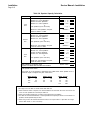
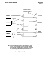
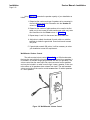
1
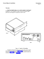
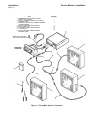
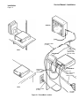
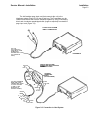
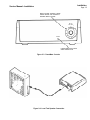
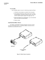
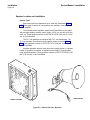
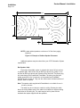
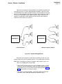
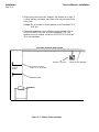
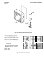
AT&T
®
PagePac 20 Voice Paging System
PowerMate™
Service Manual—Installation
®
PagePac 20 Voice Paging System
PowerMate™
Service Manual—Installation
SM-722050-001
999-500-200IS
Issue 4, Nov. 1987
HARRIS CORPORATION Dracon Division
809 Calle Plano, Camarillo, California 93010, U.S.A.
Telex 182327
Telephone 805/987-9511
© Harris Corporation Dracon Division 1985
To order copies of this manual:
CALL:
Your AT&T information Systems Sales Representative
or
Your Business Sales and Service Center
or
The AT&T Customer Information Center, 1-800-432-6600
WRITE:
AT&T Customer Information Center
P.O. Box 19901
Indianapolis, IN 46219
ORDER:
Document Number 999-500-200IS
Table of Contents
Service Manual—Installation
Page i
Table of Contents
Page
1. Introduction
1-1
PagePac 20 Voice Paging System
1-1
Overview
1-3
Features
1-4
Components
1-5
Warranty Statement
1-5
2. Installation
2-1
Overview
2-1
PowerMate Installation Procedure
2-1
Select PowerMate Location and Install Powermate
2-1
Connect PowerMate to the Telephone System
and Apply AC Power
2-4
Test PowerMate by Connecting a Speaker Locally
and Paging
2-4
Connect Local Speaker
24
Test PowerMate
2-6
Install Optional Music Source
2-6
Speaker Locations and Installation
2-8
Speaker Types
2-8
Speaker Capacity
2-9
Wall-Mounted Volume Control
2-12
Determine Speaker Locations
2-13
Run Speaker Cable
2-14
Install Speakers
2-17
Universal Cabinet Speakers
2-17
Universal Horn Speakers
2-19
Connect Speaker Cable
2-21
Adjust Background Music and Page Volume
2-21
3. Maintenance and Troubleshooting
3-1
Service Manual—Installation
List of Figures/Tables
Page ii
List of Figures
Page
1-1
PagePac 20 PowerMate
1-3
1-2
PowerMate Paging System
1-4
1-3
PowerMate System Components
1-5
2-1
PowerMate Location
2-2
2-2
Connection to Host System
2-3
2-3
PowerMate Controls
2-5
2-4
Local Test Speaker Connection
2-5
2-5
Music Source Connection
2-6
2-6
Cabinet and Horn Speakers
2-8
2-7
Typical Cable Runs
2-11
2-8
Wall-Mounted Volume Control
2-12
2-9
Example of Cabinet Speaker Placement
2-14
2-10 Speaker Wiring Methods
2-15
2-11 Speaker Cable Installation
2-16
2-12 Universal Cabinet Speaker Mounting
2-18
2-13 Screw Anchor Installation
2-18
2-14 Universal Horn Speaker Installation
2-20
2-15 Pole Mounted Universal Horn Speaker
2-20
2-16 Speaker Connections
2-22
2-17 Cabinet Speaker Volume Adjustment
2-22
List of Tables
Page
1-A
PagePac 20 System Modules
1-1
1-B
PagePac 20 System Manuals
1-2
2-A
Speaker Capacity Calculation
2-10
Introduction
Service Manual—Installation
Page 1-1
1. Introduction
PagePac 20 Voice Paging System
PagePac 20 uses a modular approach to provide maximum flexibility in
system design. The basic system modules are described in Table 1-A.
Table 1-A. PagePac 20 System Modules
Module
Function
PowerMate
System amplifier, contains music/page
switch, provides single-zone, one-way
paging with either 70V or voice coil
output to speakers.
MusicMate
Used with PowerMate to provide background
Music to paging system. May also be used to
provide music-on-hold to host telephone
system. An alternate music source, such as
FM tuner, may be used in place of MusicMate.
TalkMate
Used with PowerMate to provide talk-back
in single-zone systems.
ZoneMate 3
Used with PowerMate to provide three paging
zones in conjunction with MERLIN 1030 or
3070 CS. TalkMate is required for talk-back.
ZoneMate 3 may use music source provided
through host telephone system, or MusicMate
or alternate source may be used.
Common Control
Unit (CCU)
Used with PowerMate to provide zone paging
and talk-back in conjunction with all host
systems, except MERLIN 1030 and 3070 CS.
ZoneMate 9
Provides connections to CCU for nine
paging zones.
ZoneMate 39
Provides connections to CCU for 39 paging zones.
Service Manual—Installation
Introduction
Page 1-2
Table 1-B lists the available PagePac 20 System manuals and the
contents of each manual.
Table 1-B. PagePac 20 System Manuals
Manual
Contents
PowerMate Service Manual
999-500-200IS
General information for PowerMate
when used in single-zone paging
system. Description of speakers,
speaker placement and installation procedures.
TalkMate Service Manual
999-500-201IS
General information for connecting
TalkMate to PowerMate. Operation
of TalkMate controls and paging
procedures with talk-back.
MusicMate Service Manual
999-500-202IS
General information for connecting MusicMate to PowerMate and
operating instructions for MusicMate
ZoneMate 3 Service Manual
999-500-203IS
ZoneMate 3 connections to
PowerMate and to MERLIN CS 1030
or 3070. Speaker connections to
ZoneMate 3. ZoneMate 3 controls.
ZoneMate 9 Service Manual
999-500-204IS
CCU connections to PowerMate
and to ZoneMate 9 connection box.
CCU controls and programming.
Speaker connections to ZoneMate 9
connection box. ZoneMate 9 controls.
ZoneMate 39 Service Manual
999-500-205IS
CCU connections to PowerMate
and to ZoneMate 39 connection box.
CCU controls and programming.
Speaker connections to ZoneMate 39
connection box.
MERLIN* Connection Manual
999-500-206IS
DIMENSION* Connection Manual
999-500-207IS
HORIZON* Connection Manual
999-500-208IS
COM KEY* 416 Connection Manual
999-500-208IS
Key System Connection Manual
999-500-210IS
Specific interface information
for the host system indicated.
Interface is the same for
PowerMate, TalkMate or Common
Control Unit (CCU).
*Trademarks of AT&T Co.
Introduction
Service Manual—Installation
Page 1-3
Overview
PagePac PowerMate (Figure 1-1) is a 20-watt, telephone integrated paging system which allows telephones to be used for paging over the system
loudspeakers. The PowerMate is compact, housed in an attractive black
plastic case, and designed to be placed on a desk or shelf.
3.0 IN.
8.5 IN.
9.5 IN.
FRONT
REAR
Figure 1-1. PagePac 20 PowerMate
PowerMate provides basic single-zone, one-way paging. Other features
may be added to the paging system (Figure 1-2) with the optional modules
described in Table 1-A. Installation procedures for the optional modules are
contained in separate manuals (Table 1-B).
Service Manual—Installation
Introduction
Page 1-4
MUSICMATE
OR OTHER SOURCE OF MUSIC
POWERMATE
TALKMATE OR CCU
(OPTIONAL)
Figure 1-2. PowerMate Paging System
PowerMate provides either voice coil and/or 70.7V AC audio output to
the system loudspeakers. Should a major electrical problem develop, a fuse
located inside the unit provides protection from fire hazards. The unit protects
itself by switching the output power off when the loudspeaker load exceeds
the unit capacity, or when a short circuit is connected to the loudspeaker output jack.
Features
●
●
●
●
●
●
●
●
●
Telephone-integrated voice paging.
Compatible with most PBX and key telephone systems.
20-watt output, at 125V AC.
Choice of voice coil and/or 70.7V AC output.
Compact, ideal for desk or shelf.
Paging compressor equalizes loud and soft voices during page.
Compatible with external music.
Music/page switch provides noiseless switching between music and page.
Weighs 6.5 pounds.
Service Manual—Installation
Introduction
Page 1-5
Components
PowerMate is self-contained; all necessary electrical components are
contained within the unit. These components include: a power supply,
amplifier, music preamplifier, paging preamplifier, paging compressor,
music/page switch and telephone interface. The only external components
required are Y-connectors, loudspeakers and speaker cable. The items supplied with the starter PowerMate system are shown and listed in Figure 1-3.
The PowerMate may also be ordered separately.
Note: The speaker cable supplied with PowerMate is not suitable for
use in air-return plenums.
Warranty Statement
All terms and conditions of your agreement with AT&T Information
Systems apply.
For service information, call the AT&T Information Systems Service
Number that is provided for your communications system.
For warranty and non-warranty service of this product, Harris Corporation Dracon Division acts solely as a service agent for AT&T Information
Systems and any claims are to be made solely with AT&T.
Service Manual—Installation
Introduction
Page 1-6
Item
1. POWERMATE MODULE INSTALLATION
MANUAL (NOT SHOWN)
2. 6-FOOT, CONNECTORIZED FULL OR HALF—
MODULAR CORD
3. UNIVERSAL (VOICE COIL) CABINET SPEAKER
(CONNECTORIZED)
4. BOX OF INSULATED WIRE STAPLES
5. NYLON CABLE TIE
6. NYLON WALL ANCHOR AND SCREW
7. Y-CONNECTOR
8. 24-FOOT SECTION CONNECTORIZED
SPEAKER CABLE
Quantity
1
1
3
1
12
6
4
12
(SOME HOST SYSTEMS
USE FULL-MODULAR CORD)
MUSICMATE
(OPTIONAL)
Figure 1-3. PowerMate System Components
Installation
Service Manual—Installation
Page 2-1
2. Installation
Overview
This section contains PowerMate installation procedures, PowerMate
power connections, optional music source connections and adjustments,
speaker installation, and speaker connection.
PowerMate Installation Procedure
The major steps required to install the PowerMate paging system are as
follows:
1. Select PowerMate location and install PowerMate.
2. Connect PowerMate to telephone system and then supply AC
power (see separate instructions supplied for your host system).
3. Test PowerMate by connecting a speaker locally and paging
(see separate instructions supplied for your host system).
4. Install optional MusicMate or alternate music source.
5. Test music source for background music (over locally connected
loudspeaker) and for music-on-hold using telephone system.
6. Adjust music-on-hold volume on host system.
7. Determine speaker locations and run speaker cable.
8. Install speakers.
9. Adjust background music and paging volume.
Note: Installation and operation instructions for all optional
modules are provided with the units.
The steps listed above are generally performed in the order shown. The
procedure for performing each step is detailed in the paragraphs that follow.
Select PowerMate Location and Install PowerMate
The PowerMate is designed to be placed on a desk, shelf or similar surface (Figure 2-1) within 6 feet of a power outlet. The outlet used should not
be controlled by a regular wall switch that might be mistaken for a light
switch.
Service Manual—Installation
Installation
Page 2-2
SPEAKER
SPEAKER CABLE
(24 FEET)
SHELF
MUSICMATE
MUSICMATE
CORDS
(18 INCHES)
Y-CONNECTOR
TO SPEAKER
(ONE OR TWO
MAY BE USED)
POWERMATE
FULL OR
HALF-MODULAR
PAGE INPUT
CORD (6 FEET)
DESK
POWER CORD
(6 FEET)
TO HOST
SYSTEM
Figure 2-1. PowerMate Location
Installation
Service Manual—Installation
Page 2-3
The half-modular page input cord that connects the unit to the
telephone system (Figure 2-2) is also 6 feet long. The PowerMate may be
located more than 6 feet from the telephone system by using a connecting
block and 4-conductor spade-tipped cord (length as required) to extend the
page input cord (Figure 2-2).
TYPICAL HOST SYSTEM
DIRECT CONNECTION
FULL OR
HALF-MODULAR
PAGE INPUT CORD
(SOME HOST
SYSTEMS USE
FULL-MODULAR
CORD)
POWERMATE
TYPICAL HOST SYSTEM
CONNECTION USING OPTIONAL
CONNECTING BLOCK
YELLOW
RED
OPTIONAL
CONNECTING
BLOCK
(NOT PROVIDED)
GREEN
BLACK
300 FEET MAXIMUM
WIRE RUN FROM
CONNECTING BLOCK
TO HOST SYSTEM
(C AND C1 ARE
SHORTED TO
ACCESS PAGING)
RED
YELLOW
GREEN
BLACK
GREEN
RED
T
R
C
C1
BLACK
YELLOW
Figure 2-2. Connection to Host System
Service Manual—Installation
Installation
Page 2-4
Connect PowerMate To The Telephone System And Apply
AC Power
The page input cord that connects the telephone system to the PowerMate
has a standard 4-wire RJ-18 type plug or 25-pair connector on one end,
depending on the host system, and a standard plug or spade-tip leads on the
other end. For systems requiring a 25-pair connector, a special modular/25-pair
connector is provided with the page input cord. The page input cord is
approximately 6 feet long and is shipped with the PowerMate. Page input
cords (modular or half-modular as required) for each specific host telephone
system are supplied with a set of installation instructions.
The page input cord conductors are color-coded black, red, green, and
yellow, and are connected to the host system as described below
(Figure 2-2):
1. Connect black wire to the paired dry contact control lead C.
2. Connect yellow wire to the paired dry contact control lead C1.
3. Connect red wire to system ring R.
4. Connect green wire to system tip T.
Note: Tip and ring are paging input leads. Leads C and C1 are
shorted through a switch when paging is accessed. If a
connecting block is used, maintain the same color through
the block.
After all connections to the telephone system are completed, apply
power to the unit as follows:
1. Set the MUSIC VOLUME control to OFF.
2. Plug the unit’s power cord into an AC outlet.
3. Turn the MUSIC VOLUME control clockwise (Figure 2-3); you
will hear a click and the POWER indicator will come on.
Test PowerMate By Connecting A Speaker Locally And Paging
Connect Local Speaker
Use a cabinet speaker for the local test speaker. Use a section of
speaker cable to connect speaker input connector to OUTPUTS VOICE COIL
jack J5 on the rear of the PowerMate (Figure 2-4).
Installation
Service Manual—Installation
Page 2-5
MUSIC VOLUME CONTROL TURNS
POWER ON/OFF AND CONTROLS
SPEAKER MUSIC VOLUME
MUSIC
VOLUME
POWER
POWER INDICATOR LIGHTS
WHEN POWER IS ON
Figure 2-3. PowerMate Controls
Figure 2-4. Local Test Speaker Connection
Service Manual—Installation
Installation
Page 2-6
Test PowerMate
Test PowerMate system to ensure it is functioning normally as follows:
1. Lift handset of any telephone connected to the host system.
2. Access paging by dialing the paging access code or pressing
the page button(s), depending on the host system. See instructions for individual systems supplied with page input cord.
3. Speak into telephone in a normal manner; your voice should be
heard in the locally connected speaker.
4. Replace handset.
Install Optional Music Source
The PagePac 20 MusicMate is specially designed to be used in conjunction with the PowerMate (Figure 2-5). Detailed installation instructions for the
MusicMate are provided with each unit.
MUSICMATE
TO HI-FI OR SIMILAR
SOURCE
Figure 2-5. Music Source Connection
Service Manual—Installation
Installation
Page 2-7
If a music source other than MusicMate is used for background music, a
2-wire cable with an RCA phono plug interconnects that source with PowerMate MUSIC IN jack J2. The other end of the cable connects to the output of
that music source (Figure 2-5).
Note: The background music level is adjusted with the PowerMate
MUSIC VOLUME control. The music source volume control
should be turned all the way down.
Test music function as follows:
1. Lift handset of any telephone connected to the host system.
2. Access page as required by the host system. Music should stop
when the paging system is accessed.
3. Replace handset; music should return to the local speaker.
Adjust music-on-hold volume (if provided) as follows:
1. Have an outside call placed into the host system; place call on
hold. The caller should hear music while on hold.
2. If necessary, adjust music volume with the volume control provided by the host system.
Note: Proprietors of background music systems in public places
are referred to Public Law 94-553, effective 1/1/78.
Licenses may be required from ASCAP and/or BMI.
Service Manual—Installation
Installation
Page 2-8
Speaker Location and Installation
Speaker Types
Both cabinet and horn speakers may be used with PowerMate (Figure
2-6). Three types of cabinet or horn speakers are available: universal, 70.7
volt, or amplified.
The universal cabinet speakers supplied with PowerMate are the standard cone-type speaker normally used in radios, HI-FIs, etc, but with a 45-ohm
voice coil. These speakers connect to OUTPUTS VOICE COIL jack J5 on the
rear of the PowerMate.
The 70.7 volt speakers are equipped with 70.7 volt transformers. The
70.7 volt speakers are used when more speaker power is required (Table
2-A). These speakers connect to OUTPUTS 70.7V LINE jack J4 on the rear
of the PowerMate.
Amplified speakers are also used where more paging power or a greater
number of speakers is required. A separate power supply is required when
using amplified speakers. These speakers connect to OUTPUTS VOICE COIL
jack J5 on the rear of the PowerMate.
HORN SPEAKER
CABINET SPEAKER
Figure 2-6. Cabinet And Horn Speakers
Service Manual—Installation
Installation
Page 2-9
Speaker Capacity
The maximum number of speakers that can be used with PowerMate is
determined by the speaker types used (cone and/or horn) and the number of
24-foot speaker cable sections in a cable run (Table 2-A).
A cable run is any combination of speaker(s), cable section(s), and
Y-connector(s) on a common line that connects to the PowerMate. There may
be more than one cable run in the system. Cable runs may be wired using
the home run method (Figure 2-10) with only a single speaker per run, or
using the speaker-to-speaker method (Figure 2-10) with several speakers per
run. Examples of typical cable runs are shown in Figure 2-7.
Use the following information as a guide in determining what speaker
type to use in your installation:
●
Universal cabinet speaker (cone) and/or ceiling speaker— General
office environment, stockrooms, lobbies, halls, etc. The cone is designed
to provide maximum clarity not maximum volume of noise, therefore, the
key is to have it in a talking environment rather than a shouting
environment. The universal cone speaker has a volume control for
adjusting loudness.
●
Universal horn speaker— Large areas such as a quiet warehouse,
business machine area, assembly area, or yard area. The horn has more
noise penetrating power than the cone, hence you can cover a large
area, or a noisier area.
Note: You must use an external attenuator with the horn to reduce
volume as there is no volume control for adjusting loudness.
●
70.7 volt speaker— On occasion you may find that the universal
cone/horns will not handle a difficult area (i.e. high noise areas). Since
high noise areas require more powerful speakers, you will be limited to
the number of 70.7 volt speakers you can use (as shown in Table 2-A a
15W horn set at 7.5W would use ½ of the 300 points available to your
system). However, 70.7 volt horns have adjustable tap settings, so an
external attenuator is only required if you need to vary the volume to
conform to varying noise levels in the room. Cable length need not be
considered when using 70.7 volt horns.
Service Manual—Installation
Installation
Page 2-10
Table 2-A. Speaker Capacity Calculation
Factors
Cable Runs
÷ 24 =
x 4 =
x 2 =
x 30 =
V.C. Cable Length In Feet
Number V.C. Cone Speakers
Number P-TEC/5 Speakers
Number V.C. Horn Speakers
or
70V Speakers (Cone and Horn)
First
Run
x
Subtotal =
NOTE: For 70V speakers, see point
values at bottom of table.
÷ 24 =
x 4 =
x 2 =
x 30 =
V.C. Cable Length In Feet
Number V.C. Cone Speakers
Number P-TEC/5 Speakers
Number V.C. Horn Speakers
or
70V Speakers (Cone and Horn)
Second
Run
x (*) =
Subtotal =
NOTE: For 70V speakers, see point
values at bottom of table.
÷ 24 =
x 4 =
x 2 =
x 30 =
V.C. Cable Length In Feet
Number V.C. Cone Speakers
Number P-TEC/5 Speakers
Number V.C. Horn Speakers
or
70V Speakers (Cone and Horn)
Third
Run
(*) =
x (*) =
Subtotal =
NOTE: For 70V speakers, see point
values at bottom of table.
Add subtotals to get System Total.
System Total MUST NOT EXCEED 300 POINTS.
System Total =
*70V Speaker Point Values
Point value for a 70V speaker is determined from table below. Each speaker set to a
particular output is assigned the point value shown.
Watts Points
.025
.250
.500
2.5
5.0
10.0
Watts Points
Watts Points
1.0
2.0
2.5
3.7
5.0
7.5
15.0
20
40
50
76
100
150
300
Notes:
1. No single voice coil cable run should exceed 600 cable feet.
2. When maximum volume is required, it is recommended that not more than two voice coil horns or four
voice coil cone speakers be connected per cable run.
3. When using existing speaker wire, be aware of the 600 foot-per-run limitation.
4. If a cable run must exceed 600 feet, or if more speakers are required per home run and volume is a
problem, 70-volt speakers may be used.
5. When using a voice coil wall-mounted volume control, it has a point value of 1 (the same as a single
24-foot cable section, or one Y-connector).
Installation
Service Manual—Installation
Page 2-11
THESE ARE NOT SEPARATE
RUNS BECAUSE THEY ARE
CONNECTED THROUGH OTHER
SPEAKERS AND NOT DIRECTLY
TO POWERMATE
POWERMATE
SINGLE RUN
EXAMPLE 1
1 CABLE RUN
Y-CONNECTOR
RUN 1
EXAMPLE 2
2 CABLE RUNS
POWERMATE
RUN 2
RUN 1
RUN 2
POWERMATE
RUN 3
Y-CONNECTOR
Note: Each individual cable run originates at the PowerMate. Note that in
example 1, the runs is extended beyond the first speaker. The cable
sections beyond the first speaker do not constitute new runs, because
they are connected through other speakers and not directly to the
PowerMate. In examples 2 and 3, Y-connectors are used to connect
the individual runs directly to the PowerMate.
Figure 2-7. Typical Cable Runs
EXAMPLE 3
3 CABLE RUNS
Service Manual—Installation
Installation
Page 2-12
Using Table 2-A, determine the speaker capacity of your installation as
follows:
1. Determine the number and type of speakers to be connected in
the first cable run; enter this information into the Number Of
column in Table 2-A.
2. Determine the number of cable sections to be used in the first
cable run (do not exceed 25 cable sections per cable run); enter
this information into the Points column in Table 2-A.
3. Repeat steps 1 and 2 for the second and third cable runs.
4. Add points to obtain the subtotal for each cable run; add the
subtotals to obtain the grand total. Grand total cannot exceed
300 points.
5. If grand total exceeds 300 points, it will be necessary to revise
your installation to meet this requirement.
Wall-Mounted Volume Control
The wall-mounted volume control (Figure 2-8) is a 100-ohm attenuator
that may be used with both universal cabinet and universal horn speakers. It
is installed in a standard single-gang electrical wall box (not provided). This
volume control has the same input and output connectors as the speakers
and may be included in a cable run as though it were a speaker. It then controls volume of all speakers down stream from itself. The wall-mounted
volume control should be used to control no more than 12 cabinet speakers
or 3 horn speakers.
Figure 2-8. Wall-Mounted Volume Control
Service Manual—Installation
Installation
Page 2-13
Determine Speaker Locations
The Universal cabinet Speakers are not weatherproof and must be used
indoors. The speakers supplied with PowerMate are 45-ohm, low voltage,
voice coil, bidirectional speakers in walnut grain wood cabinets. Their power
output is adjustable over the range of 0.125 watt to 0.25 watt with a screwtype attenuator (volume control). Each cabinet speaker will generally cover
approximately 400 square feet, depending on the background noise in the
area. The 70.7 volt cabinet speakers are also available but are not modularconnected.
Horn Speakers supplied for this system are weatherproof speakers.
Horn speakers are used when the paging power requirement exceeds the ¼
watt cabinet speaker capacity, or in noisy restaurants, offices, some factories,
etc. Horn speakers should be mounted as high as possible, except when talkback is needed. Minimum effective height is approximately 15 feet. Higher
mounting provides: wider coverage, even sound distribution, penetration of
close noise, and less discomfort to people close to the horn speaker.
When a horn speaker is used for talk-back, the mounting height is lower
(8 to 12 feet) and it is usually adjusted for a lower power level.
An example of cabinet speaker placement is shown in Figure 2-9. As
shown, the total floor space within the coverage area for the three cabinet
speakers is 1125 square feet. The speakers should be placed for the best
possible coverage. Covering an area adequately with sound is much like
providing adequate lighting. Think of the speakers as light bulbs and consider
their location in the same manner. The object is to achieve as even a
distribution of sound as possible.
Acoustic feedback must be considered when placing speakers. Acoustic
feedback is the squeal caused when a loudspeaker is located too close to
the paging telephone. Should feedback occur, either the speaker or the
telephone must be relocated.
Locate cabinet speakers a minimum of 10 feet and horn speakers a
minimum of 25 feet from the paging telephone.
Another consideration is the distance between people and the speakers.
The speaker power setting must be high enough to allow a person across the
room to hear easily. Another person located right below the speaker might
think it is too loud. Because the speakers are mounted near the ceiling, the
problem is overcome easily by not placing a speaker directly above anyone’s
desk.
Service Manual—Installation
Installation
Page 2-14
50 FT.
SPEAKER
TELEPHONE
20 FT.
25 FT.
TOTAL SQ. FT. 1125
25 FT.
5 FT.
25 FT.
NOTE: Locate cabinet speakers a minimum of 10 feet from paging
telephone.
Figure 2-9. Example of Cabinet Speaker Placement
Additional speakers may be ordered from your AT&T Information System
representative.
Run Speaker Cable
Each starter PowerMate system is shipped with twelve 24-foot sections
of speaker cable. Each section has an RCA type phono plug (male) on one
end and an RCA type phono jack (female) on the other end. The phono plug
end must always point towards the PowerMate. The phono plug and jack
enable connection to the Y-connector on the speaker and PowerMate
OUTPUTS jacks J4 and J5. They can also interconnect individual sections of
speaker cable as required.
Note: The speaker cable supplied with PowerMate is not suitable for use in
air-return plenums.
The cable may be run above or under the ceiling. Running the cable
above the ceiling allows some of the cable to be hidden but requires making
small holes in the ceiling tile. The cable may be held in place with the
insulated wire staples supplied with the speakers.
Installation
Service Manual—Installation
Page 2-15
There are two methods of wiring speakers: from speaker-to-speaker and
Home Run (Figure 2-10). When wiring speaker-to-speaker, cable is run from
the PowerMate to the nearest speaker location, from that location to the next,
and so on, until all locations are connected. When wiring Home Run, cable is
run from the PowerMate to each speaker location, using Y-connectors as
needed. A combination of both methods may be used, but the maximum
distance for each cable run is 600 feet.
POWERMATE
HOME RUN METHOD
POWERMATE
SPEAKER-TO-SPEAKER METHOD
Figure 2-10. Speaker Wiring Methods
Determine which method or combination of methods you will use in the
paging area(s) and mark the speaker locations. Run speaker cable as follows:
Note: When connecting two sections of speaker cable together, secure connection by wrapping with electrical tape.
1. Starting with the phono plug end at the PowerMate location, connect
sections of cable as necessary to reach the initial speaker location(s);
secure cable every 16 to 20 inches with the staples provided (Figure
2-11), being careful not to puncture cable.
2. Run cable to individual speakers, connecting individual sections as
necessary; secure cable with staples as indicated in step 1.
Service Manual—Installation
Installation
Page 2-16
3. Excess cable should be rolled, strapped, and secured out of sight. If
a ceiling opening is available, the excess cable may be stored in the
ceiling area.
Caution: Do not connect Universal speakers to the PowerMate 70.7V
LINE jack.
4. If Universal speakers are to be installed, connect speaker cable to
OUTPUTS VOICE COIL jack J5 on the PowerMate. If 70.7 volt
speakers are to be installed, connect to OUTPUTS 70.7V LINE jack
J4 on the PowerMate.
RUN CABLE ABOVE OR UNDER CEILING
SPEAKER LOCATION
16 TO 20
INCHES
INSULATED STAPLES
EVERY 16 TO 20 INCHES
SPEAKER CABLE
POWERMATE
Figure 2-11. Speaker Cable Installation
CABLE TO NEXT SPEAKER
Service Manual—Installation
Installation
Page 2-17
Install Speakers
Tools that may be needed to install horn and cabinet speakers are:
●
●
●
●
Screwdriver
Hammer
Drill
Drill bit, 5/16-inch
Universal Cabinet Speakers
The Cabinet Speakers are designed for mounting on a wall or ceiling
(Figure 2-12). Mount as follows:
Note: If it is necessary to mount the cabinet speaker to a pole, secure mounting bracket to the pole with banding tape or a hose-type clamp (not
provided), and proceed to step 4.
1. Using the mounting bracket as a template, mark two screw anchor
holes on a flat mounting surface. The screw anchors go in the two
outside keyholes on the base of the bracket. Check the position of
speaker for ease of wiring and volume adjustment; turn volume
control setting to the left.
2. Install screw anchors as described in Figure 2-13; leave about ¼
inch of each screw exposed.
3. Mount bracket over the screw anchors; install a 1-inch sheet metal
screw in the center hole to keep bracket from moving.
4. After mounting the bracket, use the screws taped to the top of the
cabinet speaker to attach the speaker to the bracket as shown in
Figure 2-12.
Service Manual—Installation
Installation
Page 2-18
SCREW
MOUNTING
BRACKET
SPEAKER
Figure 2-12. Universal Cabinet Speaker Mounting
1. Drill a 5/16 in. hole for each anchor. Fold the
anchor by pushing the tip toward the center.
1
2
3
4
5
6
2. Insert the anchor in its hole and lightly tap it until
flush with the wall.
3. Open the anchor inside the wall with the red key
(provided with the anchors). Insert the key and
push, but do not force or hammer the key.
Note: Some walls may be too thick to allow the anchor
to “pop” open. The anchor will still function, as
shown in 5 and 6.
4. Mount the item to be attached to the wall and insert
the screw. Tighten the screw until it is flush and
then tighten one-half turn more. DO NOT overtighten.
5. Anchor in thick wall.
6. Anchor in solid wall.
Figure 2-13. Screw Anchor Installation
Service Manual—Installation
Installation
Page 2-19
Universal Horn Speakers
The Horn Speaker should be removed from the mounting bracket to
connect the bracket to the wall or ceiling (Figure 2-14).
To remove bracket, loosen the wing nut and remove bracket from the
base of the horn.
Mount horn speaker as follows:
Note 1: When installing horn speakers, the nylon wall anchors and
screws provided with the speakers will be suitable for most
installations. However, some installations may require special
hardware obtained locally.
Note 2: The horn speaker mounting bracket also has a slot that allows
for mounting on a pole (Figure 2-15). If it is necessary to mount
bracket on a pole, use metal banding tape or a large hose-type
clamp (not provided), then proceed to step 4.
1. Use bracket base as a template to mark mounting holes.
2. Install screw anchors as described in Figure 2-13.
3. Secure bracket to anchors with the screws provided.
4. Reconnect horn to bracket. Point horn towards the center of the
paging area and lock in position with the wing nut.
Service Manual—Installation
Installation
Page 2-20
WING NUT
SCREW
MOUNTING
BRACKET
Figure 2-14. Universal Horn Speaker Installation
WING NUT
METAL BANDING
TAPE
MOUNTING
BRACKET
Figure 2-15. Pole Mounted Universal Horn Speaker
Service Manual—Installation
Installation
Page 2-21
Connect Speaker Cable
When all speakers have been installed, connect individual speakers by
plugging the male phono plug on the speaker Y-connector into the female
jack on the speaker cable as shown in Figure 2-16 (note that the speaker
phono plug points toward the PowerMate). For speaker-to-speaker wiring,
plug the cable going to the next speaker into the jack of the preceding
speaker and continue wiring all speakers and horns. Always keep the phono
plugs pointing toward the PowerMate.
The Y-type connectors provided with the speakers, horns, and PowerMate can be used at any cable location. In Figure 2-16, two Y-connectors are
used, one at the PowerMate and the other between the two 24-foot sections
of speaker cable. Another Y-connector could be added at each of these
locations or at the speakers.
Adjust Background Music And Page Volume
Use the procedures previously outlined to test the paging system with
all speakers connected. Music, if provided, should be heard in all speakers
when a page is not in progress and switched out when paging.
Note: Specific operating instructions are provided with the page input
cord for each type of host system.
The MUSIC VOLUME control on front of the PowerMate controls only
the background music volume. Paging volume is adjusted by means of the
speaker volume control located on the side of each cabinet speaker (Figure
2-17) or with the separate wall-mounted volume control. Adjust the volume of
each speaker while a page is in progress.
It is important that each speaker be properly adjusted for paging volume
before making final adjustments to the music volume. This will assure the
best balance in loudness between music and page. Use the PowerMate
MUSIC VOLUME control to adjust the background music volume to a
desired level.
Music-on-hold volume control must be provided on the host system.
Service Manual—Installation
Installation
Page 2-22
POWERMATE
SPEAKER CABLE
(24 FEET)
Y-CONNECTOR
SPEAKER
SPEAKER CABLE
(24 FEET)
SPEAKER CABLE
(24 FEET)
SPEAKER
SPEAKER
TO NEXT SPEAKER
IF WIRING SPEAKERTO-SPEAKER
SPEAKER CABLE
(24 FEET)
Figure 2-16. Speaker Connections
VOLUME
ADJUSTMENT
VOLUME
Figure 2-17. Cabinet Speaker Volume Adjustment
Service Manual—Installation
Maintenance And
Troubleshooting
Page 3-1
3. Maintenance and Troubleshooting
Overview
Your paging system contains no user serviceable parts for repair. All
units needing repair must be returned in accordance with the paging unit
warranty or maintenance contract. The adapter in step 3, below, should be
used to isolate a PowerMate problem or host system problem.
If a problem occurs in your paging system, the following checklist
should be followed:
1. If all speakers are dead, (no music or paging), verify the
following:
●
●
●
Is power cord plugged in?
Is power available at the receptacle being used?
If the above are verified and the POWER indicator remains
off, the PowerMate needs repair.
2. If one speaker fails (no music and no paging) within a speakerto-speaker hookup, unplug speaker from the system, then plug
in a known good speaker or connect together the two cables
that were connected to the defective speaker. If one speaker
fails in a Home Run hookup, unplug the speaker from the
system, then plug in a known good speaker or leave that location open until a replacement can be obtained.
3. If all speakers have music but cannot page, unplug the page input cord from PAGE INPUT Jack J1 on the PowerMate and connect a Six-Wire In-Line Modular Adapter (Harris part number
10220-000) to jack J1 and short adapter terminal BK to G and R
to Y and plug a standard 2500-type telephone set into the
adapter.
●
●
●
Use the handset to page.
If paging can be heard, then the paging system is free of
problems (the paging audio level will be lower than normal).
If paging cannot be heard, the PowerMate needs repair.
4. If background music or paging is badly garbled, look for a short
in the speaker cables—such as a staple driven through the
cable, bad connections, etc.
5. If all speakers have paging but not background music, verify the
following (see MusicMate instructions):
●
●
●
●
●
Tune MusicMate to a strong-signal station.
Readjust Music Mate VOLUME control, if required.
Readjust Powermate MUSIC VOLUME control, if required.
Unplug and reconnect both ends of the MusicMate cord
connected to the PowerMate.
If background music is still not heard on the speakers, the
MusicMate needs repair.
Common Problems
Experience has shown that the five situations listed below cause most
Powermate™ paging system problems.
1. Too many speakers on a run (see Table 2-A).
2. Speaker runs that are too long (see Table 2-A).
3. Mixing voice-coil and 70V speakers on the same run.
4. Speakers with their volume control set too low.
5. Speaker runs plugged into the wrong PowerMate jack (voice-coil
runs plugged into 70V jack or vice versa).
(The material above was added to the current issue of this manual in March 1987.)
Service Manual—Installation
FCC Statement/Registration
Page A
Federal Communications Commission (FCC) Statement (Part 68)
This equipment is component registered with the Federal Communications Commission (FCC) in accordance with Part 68 of its Rules. In compliance with the rules, be advised of the following:
Registered equipment may not be used with Coin Telephone Lines.
Equipment may be used with Party Lines in areas where state tariffs permit
such connections and when equipment is adaptable for such service.
This equipment is registered as follows:
●
Registration Number - APF9Q9-12451-KX-N
●
Ringer Equivalence - 0.0B
If trouble is experienced, the equipment should be disconnected
(unplugged) from the interface to determine if this equipment, the host equipment, or the telephone line is the trouble source. If this equipment is determined to be malfunctioning, it should not be reconnected until repairs are
effected.
Connection to host equipment is via a 6-position modular jack (74D Connecting Block) or 50-position ribbon connector (KS-16690). Equivalent connections may be used. This equipment is designated to be installed in a foolproof manner. Permission of the host equipment owner, who may determine
the means of connection, is required for connection.
Repairs to this equipment, other than routine repairs, as stated in
the User’s Manual can be made only by the manufacturer or its
authorized agents.
If the equipment causes harm to the telephone network, the local
telephone company may temporarily discontinue your service and, if possible,
notify you in advance. If advance notice is not practical, you will be notified
as soon as possible. You will be given the opportunity to correct the problem
and informed of your right to file a complaint with the FCC.
The local telephone company may make changes in its facilities, equipment, operations, or procedures that could affect the proper functioning of
your equipment. If they do, you will be given adequate notice in writing to
allow you an opportunity to maintain uninterrupted telephone service.
FCC Statement/Registration
Service Manual—Installation
Page B
Federal Communications Commission (FCC) Registration (Part 15)
Radio Frequency Interference
The PowerMate™ unit generates and uses radio frequency energy and if
not installed and used in strict accordance with the manufacturer’s instructions, may cause interference to radio and television reception. It has been
type tested and found to comply with the limits for a Class B device in
accordance with the specifications in Subpart J of Part 15 of the FCC Rules,
which are designed to provide reasonable protection against such interference. However, there is no guarantee that interference will not occur in
a particular installation. If this equipment does cause interference to radio or
television reception, which can be determined by turning the PowerMate unit
off and on, the user is encouraged to try to correct the interference by one or
more of the following measures:
●
Reorient the radio or TV receiving antenna.
●
Relocate the PowerMate unit with respect to the radio or TV
receiver or vice-versa.
●
Plug the PowerMate unit into a different outlet so that it and the
radio or TV receiver are on different branch circuits.
If necessary, the user should consult the dealer or an experienced
radio/television technician for additional suggestions. The user may find the
following booklet, “How To Identify and Resolve Radio-TV Interference
Problems,” helpful. This booklet was prepared by the Federal Communications Commission (FCC) and is available from the U.S. Government Printing
Office, Washington, DC 20402. Stock order No. 004-000-00345-4.
Printed in U.S.A.
1/87
999-500-200IS
Issue 4, November 1987